1
IMPORTANT:
Read and save
these instructions.
I
IMPORTANT
Installer: Leave Installation Instructions
with the appliance.
Homeowner: Keep Installation Instructions
for future reference.
Save Installation Instructions for local
electrical inspector’s use.
Part No. 220038-l 010 Rev. l/4372281 Rev. A
I
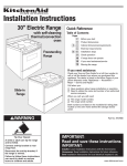
40” Electric
Freestanding
Range
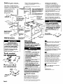
Before you start...
Check location where range will be
installed. The range should be located for
convenient use in kitchen.
Proper installation is the installer’s
responsibility. A qualified technician
should install this range. Make sure you
have every-thing necessary for correct
installation. It is the responsibility of the
installer to comply with the installation
clearance specified on the
serial/rating plate. The
serial/rating plate can
be found on the oven
frame, behind the small,
left-hand oven.
ALL OPENINGS IN THE WALL OR FLOOR
WHERERANGE IS TO BE INSTALLEDMUST
l
clearance,
Note.”
I
see
I
?
-
40-l/8”
cabinet
-
opening
Mobile home installation
The installation of this range must
conform to the Manufactured Home
Construction and Safety Standards, Title
24 CFR, part 3280 (formerly the Federal
Standard for Mobile Home Construction
and Safety, Title 24, HUD, Part 280); or
when such standard is not applicable,
the Standard for Manufactured Homes
Installations (Manufactured
Home Sites,
Communities and Setups),
ANSI A225 1/NFPA 501 A, or with local
codes*.
Note: When this range is installed in a
recreational vehicle (RV), it must be
secured to the floor. The range installed
in a mobile home must be secured to the
floor during transit.
Four-wire power supply cord must be
used in a mobile home installation. The
appliance wiring will need to be revised.
See “Electrical requirements.”
* Note: 24” min. when bottom of wood
or metal cabinet is protected
by not
less than l/4” flame retardant
millboard covered with not less than
No. 28 MSG sheet steel, 0.015”
stainless steel, 0.024” aluminum 01
0.020” copper.
30” min. clearance
between the top
of the cooking plafform and the
bottom of an unprotected
wood or
metal cabinet.
wi
depth
Note: If there is a wall on
the LEFT side, the opening
must be 42.3f8” to allow
small oven door to be
opened for removal of the
broiler pan 01 rack.
1
25” countertop
24” base cabinet
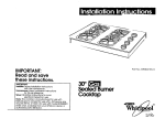
Electrical Shock Hazard
It is the customer’s responsibility:
To contact a qualified electrical
installer.
To assure that electrical installation is
adequate and in conformance with
National Electrical Code, ANSI/NFPA
70 - latest edition*, and all local
codes and ordinances.
Failure to do so could result in fire,
electrical shock or other personal
injury.
l
l
I
I
4
MA/
36” counteqop
Grounded electrical
outlet is required.
See “Electrical
requirements.”
Important:
Observe all governing
codes and ordinances.
height
Wbll receptacle
lo” max. from
right 01 lett of
center of range
;-l;{T” max. from
Oven frame must
extend beyond
cabinet fronts
by l/2”
Two anti-tip brackets
MUST be installed.
For detailed instructions,
see Panel B and Panel C.
Do Not pinch
the power cord
between the
ran e and the
wal B
5” min. clearance
from a vertical wall at
left side of range is
required to open left
hand oven door.
Personal Injury Hazard
To eliminate the risk of burns or fire,
avoid installing cabinet storage above
the cooking surface. If cabinets are
already installed, reduce the hazard of
reaching over a heated cooking
surface by installing a range hood.
The range hood should extend a
minimum of 5 inches out from the
bottom of the cabinets.
Reaching over a heated cooking
surface could result in a serious burn.
Do Not seal the
side cabinets.
Electrical
requirements
B
n All wires ending at the appliance
must terminate in ring-type terminals,
Save Installation Instructions for the
local electrical
inspector’s use.
Power supply cord is not supplied but
is available
throu h your local
electrical supply a ouses.
Electrical Shock Hazard
Electrical ground is required on
this appliance.
Do Not ground to a gas supply pipe.
Check with a qualified electrician if
you are in doubt as to whether the
appliance is properly grounded.
Only a power supply cord kit rated at
250 volts, 40 amperes and
investigated for use with ranges
should be used.
Do Not use an extension cord with
this appliance. Such use may result in
a fire, electrical shock or other
personal injury.
n Do Not have a fuse in the neutral or
grounding circuit. A fuse in the
neutral or grounding circuit could
result in electrical shock.
b Do Not plug the “pigtail” power cord
into a live wall receptacle before the
cord is permanently connected to
the terminal block. To do so may
result in personal injury from electrical
shock.
:ailure to follow these instructions could
esult in serious injury or death.
.~
If codes permit and a separate grounding
wire is used, it is recommended that a
qualified electrician determine that the
grounding path is adequate.
C
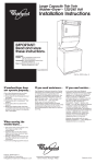
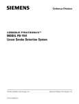
n Local codes may permit the use
of flexible type 40-ampere U.L.-listed
power supply cord (pigtail) with no
smaller than No. 8 copper wire to match
three-wire receptacle of NEMA-type
lo-50R as shown in Figure 1. A U.L.-listed
strain relief must be provided at the point
the power supply cord enters the
appliance.
l
D
l
Tools needed
for installation:
n The range may be connected
directly to the fised disconnect (or circuit
breaker) box through flexible armored or
non-metallic, sheathed copper cable.
Allow at least 3 feet minimum of slack in
the line between the wall and the
appliance so that it can be moved if
servicing is ever necessary A suitable
strain relief must be provided at each
end of the copper power supply cord (at
the appliance and at the junction box).
Wire sizes (COPPER WIRE ONLY) and
connections must conform with the rating
of the appliance (40 amperes).
l
l
screwdriver
l
for installation:
A
screws
Panel A
n A three-wire or four-wire sinale
phase 120/240-volt, 60.Hz, AC only ”
electrical supply (or three-wire or fourwire 120/208-volt if specified on serial
plate) is required on a separate 40
ampere circuit, fused on both sides of the
line. Do Not fuse the neutral. A time-delay
or circuit breaker is recommended.
E
n lhe range must be connected
with copper wire only.
Copies
from:
l
of the standards
National Fire Protection
Batterymarch
Park
Quincy, Massachusetts
listed may be obtained
Association
02269
F
n FOR MOBILE HOME USE,A 4-WIRE
POWER CORD MUST BE USED.This
appliance is manufactured with ground
connected to cabinet. The ground must
be revised so the green grounding wire of
the 4-wire power cord is connected to
the cabinet. See 4-wire electrical
connection section, Panel C.
If using a 4-wire NEMA type 14-50R
receptacle, a matching 4-wire U.L.-listed
“pigtail” power cord must be used. Cord
should be type SRD or SRDT,at least
4 feet long and have all conductors
ending in ring terminals at the range. See
Figure 2. The MINIMUM conductor sizes for
the copper 4-wire power cord are:
40 ampere circuit
2, No. 8 conductors
1, No. 10 white neutral
1, No. 8 green grounding
G
n A wiring diagram is included in
literature package. The wiring diagram is
also located on the back of the range.
J-wire
receptacle
wall
(lo-5OR)
Figure 1
4-wire
receptacle
wall
(14~50R)
Figure 2
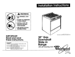
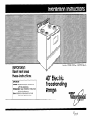
Now start...
3-wire electrical
With range in kitchen.
1
n Remove racks and other parts
from inside oven. Remove tape from
oven light switch.
Take 4
cardboard corners fro
carton. Stack one cardboard corner on
top of another. Repeat with other two
corners. Place corners lengthwise on the
floor in back of range to support range
off of skid.
n Tighten the strain relief screws.
Replace terminal block cover.
4
t
n
‘H Firmly
grasp the range
and gently lay it
on its back on the
cardboard corners.
/
10
To reduce the risk of tipping of the
appliance, the appliance must be
secured by properly installed anti-tip
brackets supplied with the range.
Save these installation instructions.
If range is moved to a new location,
the anti-tip brackets must be removed
and reinstalled in the new location.
arounding
iink
-colored
terminal I block
^SW
^ .^.
.
wtn.
&
Remove and save four
shipping bolts from the skid. Discard skid.
5
.k
Muse a U-L.-listed strain relief and
“. .insert it into the hole below the terminal
block. Insert the power supply cord
(pigtail) through the strain relief allowing
enough slack to easily attach to the
terminal block. Tighten the locking ring.
n
n Install
four shipping
as leveling legs.
n Connect the neutral (white)
wire to the silver-colored terminal screw
on the terminal block. Connect the other
two wires to the outer terminal screws on
the terminal block. Use ring-type terminals
only. Check that nuts are tight to insure
proper electrical connection.
13
U.L.-listed
strain relief
t
2
12
connection
See Panel C for 4-wire electrical
connection.
line l*
Use only rinY-type terminals to
connect the power supply. To secure the
power supply cord, use the 3/8” brass
nuts taped to cabinet below the terminal
block.
Follow instructions for the type
of installation you have.
6
14.
n Place cardboard
in front of range.
Carefully stand range upright on cardboard
7
n Remove the shipping materials
including clips that hold elements in
place, tape and protective film from
range.
8 n Adust the leveling legs to a point
where the range base does not touch
the floor.
terminal block cover
located on back of
range. Remove the
grounding strap.
Retain the
grounding screw.
Panel B
l
This appliance is manufactured with the
neutral terminal connected to
the cabinet. If local codes and
ordinances Do Not permit grounding
through the neutral, a four-wire power
supply cord, rated 250 volts, 40 amperes
and investigated for use with ranges must
be used. See 4-wire electrical
connection, Panel C.
11
n Connect grounding wire
(green) of copper power supply cord to
range with grounding screw using hole in
cabinet where grounding strap was
removed in Step 9.
l
If range will be installed with a cabinet
on both sides, mark center of cabinet
opening on floor. If back of range will
not be flush with the wall (the location
of the outlet may not allow the range
to be positioned against the wall),
mark on the floor where the back
edge of the range will be. Place
template on the floor aligning the
template centerline with the centerline
marked in the cabinet opening. Place
the back edge of the template against
the rear wall or the line marked for the
rear of the range.
Go to Step 15.
If range will be installed with a cabinet
on one side only, move range into final
position. Mark on the floor along the
side of the range that is not against the
cabinet. If back of range will not be
flush with the wall (the location of the
outlet may not allow the range to be
l
positioned against the wall), mark on
the floor where the back edge of the
range will be. Place template on the
floor and align side of template with
the line marked on the floor. Align the
back of the template with the rear wall
or the line marked for the rear of the
range.
Go to Step 15.
If range will NOT be installed against a
cabinet, move range into final position.
Mark on the floor along both sides of
the range. If back of range will not be
flush with the wall (the location of the
outlet may not allow the range to be
positioned against the wall), mark on
the floor where the back edge of the
range will be.
Place template on the floor and align
sides of template with the lines marked
on the floor. Align the back of template
with the rear wall or the line marked for
the rear of the range.
Go to step 15.
1m
4-wire electrical
Place brack;<
on floor with small flange to
front. Line up holes in anti-tip
brackets with holes in
floor. Use screws
provided to fasten
anti-tip brackets to
floor.
n
connection
Use this wiring method for mobile homes
and whenever 4-wire installation is
required.
U.L.-listed
strain relief
Floor Damage
Keep cardboard under range when
moving range.
Failure to do so could cause damage
to floor covering.
17
A
2
n Use a U.L.-listed strain relief and
insert it into the hole below the terminal
block. Insert the power supply cord
through the strain relief allowing enough
slack to easily attach to the terminal
block. Tighten the locking ring.
n Move range close to final
position. Remove cardboard from under
range. Plug power supply cord into
grounded outlet.
back edge
of range or
rear wall,
unding
screw
link
B
-
n Remove the aroundina link screw
from the range frame. Save tt?e grounding
screw. Bend up the grounding link so that it
does not contact the range.
Carefully move range to final position.
Remove storage drawer. Check that rear
leveling legs are engaged in the anti-tip
brackets. If a leveling leg is not properly
engaged, remove and reposition the
bracket to insure that the leveling leg f its
properly in the bracket.
If template is not available...
l
l
l
and there will be cabinets on both sides
of range, mark on the floor lines that
are l/2” from rear wall, 3/4” from each
side of the cabinet walls and
19-l /4” from each side of the centerline
of the cabinet opening.
Place anti-tip brackets on floor with
small flanges to front. Align brackets
with lines. Mark location of four
mounting holes for anti-tip brackets,
Go to Step 15.
and there will be a cabinet on one side
only, move range into final position.
Mark on the floor along the side of the
range that is not against the cabinet.
Determine the center point between
the cabinet and the line drawn along
the side of range. Mark lines 19- l/4”
from each side of the center point.
Mark on the floor a line l/2” from rear
wall.
Place anti-tip brackets on floor with
small flanges to front. Align brackets
with lines. Mark location of four
mounting holes for anti-tip brackets,
Go to Step 15.
and there will be no cabinets against
range, move range into final position.
Mark on the floor along both sides of
the range. Determine the center point
between the lines drawn for the point.
Mark on the floor a line l/2” from rear
wall.
Place anti-tip brackets on floor with
small flanges to front. Align brackets
with lines. Mark location of four
mounting holes for anti-tip brackets.
Go to step 15.
19.
Place rack in oven. Place level on rack,
first side to side; then front to back. If the
range is not level, pull the range forward
until rear leveling legs are removed from
the brackets. Adjust the legs up or down
until range is level.
Push range back into position. Check
that the rear leveling legs are engaged in
the brackets, Replace storage drawer.
20
n Push in and turn each surface
unit control knob to ‘HI” position. Check
the operation of the cooktop elements
and indicator lights.
21
W Check the operation of the
right (large) oven.
Bake element:
Set the right oven selector control knob
to ‘BAKE.”
Set the right oven temperature control
knob to 350°F. The bottom element
should glow red and the right oven
indicator light should be on. The top
element should become hot but not
glow red. The right oven indicator light
goes off when oven is preheated.
Broil element:
Set the right oven selector and oven
temperature control knobs to “BROIL.”
The top element should glow red and
the right oven indicator light should be
on.
l
l
l
Floor Damage
Contact a qualified carpet installer for
the best procedure to drill mounting
holes through your type carpet.
Failure to do so could cause
damage to floor covering.
15
n To mount antitip brackets to wood
floor, drill a 3/l 6”
hole, l/2” deep at
each mounting
hole location,
To mount anti-tip
brackets to concrete
or ceramic floor, use /
e
a masonry drill bit to
drill a 3/16” hole at each mounting hole
location. Tap plastic anchors into
mounting holes in floor with hammer,
Panel C
C
w Connect the green grounding
wire on the range using the grounding
screw removed in Step B. The green
grounding wire must be attached first
and must not contact any other terminal.
silvercolored
green
Insulated
wil ‘8
neutral
(white)
W&L
I
D
\
A
J@+
’
wire
U.L.-listed
strain relief
n Connect the neutral (white)
wire to the center, silver-colored terminal
screw on the terminal block. Connect the
other two wires to the outer terminals on
the terminal block. Use ring-type
terminals only.
Be sure that factory-installed
nuts are tight.
n Tighten the strain relief screws.
Replace the terminal block cover.
F
n Continue
Panel B.
installation at Step 14,
22
n Check the operation of the left
(small) oven.
Bake element:
Set the left oven temperature control
knob to 350°F. The bottom element
should glow red and the left oven
indicator light should be on. The top
element should become hot but not
glow red. The left oven indicator light
goes off when oven is preheated.
Broil element:
Set the left oven temperature control
knob to “BROIL.” The top element
should glow red and the left oven
indicator light should be on.
l
l
most efficient use from your new
/ range, read your Whirlpool Use & Care \
/ Congratulations!
Guide. Keep Installation Instructions
and Guide close to range for easy
reference. The instructions will
make reinstalling your Whirlpool
range in another home as
easy as the first
1
If the range does
not operate...
For cleaning and
maintenance...
If you need
assistance...
Check that the circuit breaker is not
tripped or the fuse blown, Check that
power supply cord is plugged into wall
receptacle.
If removing the range is necessary for
cleaning and maintenance, disconnect
electrical supply.
If electrical supply is inaccessible, lift the
range slightly at the front and pull the
range away from the wall. Pull the range
out only as far as necessary to
disconnect the electric supply line.
Remove the range to complete cleaning
or maintenance.
Move range back into operating position.
Level the range. Reconnect the electrical
supply. Make sure that rear leveling legs
are engaged in the anti-tip bracket.
The Whirlpool Consumer Assistance
Center will answer any questions about
operating or maintaining your range not
covered in the Installation Instructions.
The Whirlpool Consumer Assistance
Center is open 24 hours a day, 7 days a
week. Just dial l- (800) 253-1301 - the
call is free.
When you call, you will need the range
model number and serial number. Both
numbers can be found on the
serial/rating plate located on the oven
frame behind the small, left-hand door.
q
operating
lnstructlons and cleaning
Personal Injury/Product
Damage Hazard
Do Not step, lean or sit on the range
drawer or door.
Failure to follow these instructions could
result in personal injury and/or product
damage.
If you need
sedce...
In the event that your Whirlpool
appliance should ever need service,
call the dealer from whom you
purchased the appliance or a Whirlpoolauthorized service company. A Whirlpoolauthorized service company is listed in
the Yellow Pages of your telephone
directory under “Appliances Household - Major - Service or Repair.”
You can also obtain the service
company’s name and number by dialing,
free, within the continental United States,
the Whirlpool Consumer Assistance
Center telephone number, 1- (800) 2531301. A special operator will tell you the
name and number of your nearest
Whirlpool-authorized service company.
Maintain the quality built into your
Whirlpool appliance - call a
Whirlpool-authorized
service company.
Printed on recycled paper.
Part No. 220038-1010 Rev. l/4372281
01994 Whirlpool Corporation
10% post consumer waste/
50% recovered
materials.
Rev. A
Prepared by Whirlpool Corporation, Benton Harbor, Michigan 49022
Printed in U.S.A.