1
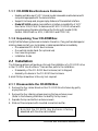
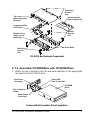
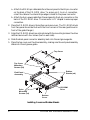
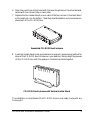
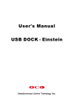
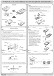
CD-ROM Box Enclosur
e
Enclosure
Installation Guide
For Models:
VP-6020
VP-6022
VP-6023
VP-6024
VP-6028
VP-6029
VP-6048
VP-6049
We are your DataBridge
TM
http://www.vipower.com
Table of Contents
1-1 Introduction ........................................................................... 1
1-1.1 CD-ROM Box Enclosure Features .............................. 1
1-1.2 ATA/ATAPI Device Compatibility ................................. 1
1-1.3 Unpacking Your CD-ROM Box .................................... 1
2-1 Installation ............................................................................ 2
2-1.1 Disassemble the CD-ROM Box ................................... 2
2-1.2 Assemble CD-ROM Box with CD-ROM Drive .............. 3
3-1 Operation with a Docking Kit ................................................. 5
3-1.1 Disconnecting the CD-ROM Box ................................. 6
PROPRIETARY NOTICE
ViPowER Inc. makes no warranty of any kind with regard to this material,
including, but not limited to, the implied warranties of merchantability and
fitness for a particular purpose. ViPowER Inc. shall not be liable for errors
contained herein or for incidental or consequential damages in connection
with the furnishing, performance, or use of this material.
This document contains proprietary information which is protected by copyright. All rights are reserved. No part of this document may be photocopied,
reproduced, or translated to another language without the written consent of
ViPowER Inc. The information contained in this document is subject to
change without notice.
PC is a trademark of International Business Machines Corporation.
Windows is a registered trademark of Microsoft Corporation.
All other trademarks belong to their respective owners.
© Copyright 2001 by ViPowER, Inc.
3/01B
1-1 Introduction
Congratulations on your purchase of one of the following CD-ROM Box Enclosures.
Each CD-ROM Box Enclosure is an external enclosure which is designed to enable
portable, hot-swap, plug-and-play operation of same-interface type 5.25” devices
installed in the box.
VP-6020 for IDE/ATA/ATAPI devices
VP-6022 for SCSI (50-pin) interface
VP-6024 for IDE Shuttle Module
VP-6028 for USB interface
VP-6029 for FireWire 1394 interface
VP-6048 for USB interface with Mobile Rack
VP-6049 for FireWire 1394 interface with Mobile Rack
If you purchased the VP-6020 CD-ROM Box, note that it is designed to enable crossplatform, portable hot-swap, plug-and-play operation of 5.25” IDE or ATA/ATAPI
devices with different interfaces using the following available interface Docking Kits:
VP-8052 SCSIdock Docking Kit
VP-8053 Wide SCSIdock Docking Kit
VP-8055 PARALLELdock Docking Kit
VP-8056 PCMCIAdock Docking Kit
VP-8057 CARDBUSdock Docking Kit
VP-8058 USBdock Docking Kit
VP-8059 FireWire 1394 Docking Kit
When used with any of the Docking Kits, the CD-ROM Box provides the perfect
solution for portable use of removable media devices with Notebooks, iMac,
Net-PC, Micro ATX PC, LCD panel PC, Mac and PC desktop computers equipped
with the same interface as the Docking Kit.
This manual will guide you through the steps for installing a CD-ROM drive in the
Model 6020 CD-ROM Box Enclosure for 5.25” IDE/ATA/ATAPI devices.
NOTE: Except for device types and connector
details unique to each interface, the basic procedures
for installing devices in any CD-ROM Box Enclosure
is the same.
CD-ROM Box Enclosure Installation Guide
1
1-1.1 CD-ROM Box Enclosure Features
• Enables portable use of 5.25” internal model removable media devices with
computers equipped with the same interface
• Supports hot-swap and plug-and-play features of the selected interface
• Model VP-6020: enables cross-platform interface compatibility of 5.25”
form factor IDE/ATA/ATA devices and ATAPI CD-ROM drives with
computers using the same interface as the Docking Kit model (USB,
Parallel, 1394/FireWire, SCSI, CARDBUS and PCMCIA).
1-1.2 Unpacking Your CD-ROM Box
Verify that the following items are included in the carton. If any parts are damaged or
missing, please contact your local dealer or sales representative immediately.
• One assembled CD-ROM Box Enclosure
• One vertical-holder stand (for optional use)
• Four mounting screws
• Installation Guide
2-1 Installation
The following sections will guide you through the installation of a CD-ROM drive
in the CD-ROM Box Enclosure. There are two parts to the installation:
• Disassembly of the CD-ROM Box Enclosure (as it is shipped)
• Assembly of a device in the CD-ROM Box Enclosure
A small Phillips screwdriver is the only tool required.
2-1.1 Disassemble the CD-ROM Box
1. Remove the four rubber stands on the CD-ROM Box Enclosure by gently
prying them off.
2. Remove the four retaining screws securing the top enclosure cover.
(Refer to the following illustration to identify the top cover.)
3. Separate the top and bottom enclosure covers.
4. Slide out the end-panel with mounted connectors and fan .
Note that the CD-ROM Box Enclosure is factory
assembled with the drive rails installed.
2
CD-ROM Box Enclosure Installation Guide
Retaining
Screws
(x4)
Top Cover
(Note alignment
flanges)
Vertical-Holder
Stand (Optional)
Connectors/Fan
End-Panel
Rubber
Stands
(x4)
Bottom Cover
(Note cut-out
for flange)
Drive Rails
Retaining
Screws
(x4)
CD-ROM Box Enclosure Components
2-1.2 Assemble CD-ROM Box with CD-ROM Drive
1. Attach the two connectors from the end-panel assembly to the appropriate
connectors on the CD-ROM drive.
40-pin IDE
Data Connector
End-Panel
Assembly
CD-ROM
Drive
Pin-1 Colored
Stripe
4-pin Power
Connector
Power and Data Connector Drive Connections
CD-ROM Box Enclosure Installation Guide
3
a. Attach the IDE 40-pin data cable from the end-panel to the 40-pin connector
on the back of the CD-ROM drive. To ensure pin-1 to pin-1 connection,
orient the cable so the colored stripe edge is closest to the power connector.
b. Attach the 4-pin power cable from the end-panel to the 4-pin connector on the
back of the CD-ROM drive. The connector is ‘D’ shaped to ensure proper
connection.
2. Place the CD-ROM drive in the bottom enclosure cover. The CD-ROM drive’s
front face panel should be flush with the front corners of the case (positioned in
front of the guide flanges.)
3. Align the CD-ROM drive’s mounting holes with the mounting holes on the drive
rails and secure with four screws (two on each side).
4. Slide the back-panel connector assembly back into the end groove guide.
5. Place the top cover over the drive assembly, making sure the end-panel assembly
slides into its end groove guide.
Top Cover
Top Cover
Mounting
Screws (x4)
Rubber
Stands (x4)
End-Panel
Assembly
Drive
Mounting
Screws (x4)
CD-ROM
Drive
Bottom
Cover
Installing Covers and Rubber Stands
4
CD-ROM Box Enclosure Installation Guide
6. Align the cover’s mounting holes with the mounting holes on the drive rails and
secure with four screws (two on each side).
7. Replace the four rubber stands, one on each of the four corners. Orient each stand
so the raised nub is on the bottom. These help heat dissipation and provide secure
placement of the CD-ROM Box.
Assembled CD-ROM Box Enclosure
8. A vertical-holder stand is also provided as a convenient, space-saving method for
setup of the CD-ROM Box Enclosure on your desktop. Simply align the grooves
of the CD-ROM box with the guides on the stand and slide together.
CD-ROM Box Enclosure with Vertical-Holder Stand
The installation is complete and the CD-ROM drive is now ready to use with any
Docking Kit.
CD-ROM Box Enclosure Installation Guide
5
3.1 Operation with a Docking Kit
Perform the following steps (in the order given) to set up a Docking Unit with your
CD-ROM Box Enclosure for operation. (Also refer to your Docking Kit’s installation
manual for further details. Some Docking Kits do not provide a Power Select switch.)
1. For Windows 98 users: verify that the Windows 98 driver is installed (if required.)
2. Verify that the power switch on the Docking Unit is OFF.
IMPORTANT
The Power Select or Power ON/OFF switch (depending on
model) must be in the OFF position before proceeding.
For Docking units with a Power Select switch, set the switch
to the MIDDLE power OFF position before connecting the
CD-ROM Box.
Power OFF
External
Power Adapter
Use Docking Kit
Power
Power Select Switch Settings on Docking Unit (For Example VP-8058)
3. Plug the Docking Kit’s 50-pin Centronics connector into the 50-pin connector
on the back of the CD-ROM Box.
4. Using the +5V/+12V AC/DC Power Adapter:
a. With the Power Switch in the OFF position, plug in the 6-pin connector-end
of the external power adapter into its corresponding +5V/+12V power-in
connector on the Docking Unit.
b. Plug one end of the power cord into the power adapter and the other end into
an AC power source outlet.
5. Set the Power Switch to ON position:
For models with Power Select switch:
a. When using the external power adapter, set the Power Select switch to the LEFT
position. Note that the green LED on the Docking Unit should be lit,
indicating power ON. (This allows the device to warm up before connecting
to the port.)
6
CD-ROM Box Enclosure Installation Guide
b. When using the Docking Kit’s interface for power, set switch to the RIGHT
position. Note: it is recommended that you use the +5V /+12V power adapter
whenever possible.
6. Connect the Docking Kit’s interface cable into the appropriate interface port on
your computer; plug the other end into the connector port on the Docking Unit.
7. Viewing the screen, note that the plug-and-play feature will recognize the new
device and assign it as a new drive.
The device is now ready to use.
Connector
to Computer
Interface
Cable
External
Power Adapter
Docking Unit
CD-ROM Box
Power Adapter
Power Cord
Connections with Docking Unit for Operation
3-1 Disconnecting the CD-ROM Box
1. Unplug the interface cable from the Docking Unit. (Note that the drive icon will
disappear from the computer screen.)
2. Turn power on Docking Unit OFF.
3. You can now switch to another device. When connecting a new device, be sure to
follow the same sequence for setup as previously outlined in section 3.0.
Printed on recycled paper.