1
CDX-15/E 00.9.12 7:44 PM ページ 16
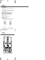
Professional Dual CD Player
OWNER'S MANUAL
VESTAX CORPORATION
VESTAX America
VESTAX (Europe)Ltd.
CDX-15/E 00.9.12 7:43 PM ページ 1
CONGRATULATIONS !
Thank you for purchasing the VESTAX CDX-15, DUAL CD PLAYER.
Please read this owner's manual carefully before you start to use the
machine, so that you will fully understand all of the special features and
enjoy the full use of the product.
C A U T I O N
FCC
IMPORTANT SAFEGUARDS
F E AT U R E S
CD SECTION
MIXER SECTION
R E A R PA N A E L
CONNECTION EXAMPLE
O P E R AT I O N
SPECIFICATIONS
1
2
4
4
5
9
10
10
11
12
CAUTION
RISK OF ELECTRIC SHOCK DO NOT OPEN
CAUTl0N:TO REDUCE THE RlSK OF ELECTRlC SHOCK
DO NOT REMOVE COVER(OR BACK)
NO USER-SERVICEABLE PARTS INSIDE
REFER SERVlCING T0 QUALIFIED SERVlCE PERSONNEL
The lightning flash with arrowhead symbol,within an equilateral triangle,is intended to
alert the user to the presence of uninsulated“dangerous voltage”within the product's
enclosure that may be of sufficient magnitude to consitute a risk of electric shock to persons.
The exclamation point within an equilateral triangle is intended to alert the user to the presence
of important operating and maintenance(servicing)instructions in the literature accompanying
the appliance.
T0 REDUCE THE RISK 0F FIRE 0R ELECTRlC SHOCK,DO NOT
EXPOSE THIS APPLIANCE T0 RAIN 0R M0ISTURE.
C A U T I O N : TO
PREVENT ELECTRIC SHOCK,MATCH BLADE OF PLUG TO
WIDE SLOT,FULLY INSERT
ATTENTION:P0UR
EVITER LES CH0CS ELECTRIQUES,INTRODUIRE LA
LAME LA PLUS LARGE DE LA FICHE DANS LA BORNE
CORRESP0NDANTE DE LA PRISE ET P0USSER JUSQU’AU
F0ND
1
CDX-15/E 00.9.12 7:43 PM ページ 2
NOTE
This equipment has been tested and found to comply with the limits for a Class B
digital device, pursuant to Part 15 of the FCC Rules. These limits are designed to
provide reasonable protection against harmful interference in a residential
installation. This equipment generates, uses and can radiate radio frequeney energy
and, If not installed and used in accordance with the lnstructions, may cause harmful
interference to radio communications. However, there is no guarantee that
interference will not occur in a particular installation. If this equipment dose cause
harmful interference to radio or television reception, which can be determined by
turning the equipment off and on, the user is encouraged to try to correct the
interference by one or more of the following measures.
●Reorient
or relocate the recelving antenna.
the separation between the equipment and receiver.
●Connect the equipment into an outlet on a circuit different from that to which the
receiver is connected.
●Consult the dealer or an experiencced radio/TV technician for help.
●Increase
NOTE
Changes or modifications may cause this unit to fail to comply wiht Part 15 of the
FCC Rules and may void the user's authority to operate the equipment.
This Class B digital apparatus meets all requirements of the Canadian Interference-Causing Equipment
Regulations.
Cet appareil numérique de la Classe B respecte toutesles exigences du Réglement sur le matérier brouilleur du
Canada.
HOW TO CONNECT A PLUG
IMPORTANT
The wires in the mains lead are coloured in
accordance with the following code:
BLUE-"NEUTRAL"("N")
BROWN-"LIVE"(L")
1.The BLUE wire must be connected to the terminal
which is marked with the letter "N" or coloured
BLACK.
2.The BROWN wire must be connected to the
terminal which is marked with the letter "L" or
coloured RED.
3.Do not connect either wires to the earth terminal in
the plug which is marked by the letter "E" or by the
safely earth symbol ↓or coloured green or greenand-yellow.
Betore replacing the plug cover, make cenain that the
cord grip is clamped over the sheath of the lead-not
simply over the two wires.
This apparatus is fitted with an approved moulded 13
Amp plug.To change a fuse in this type of plug
proceed as follows:
1.Remove fuse cover and fuse.
2.Fix new fuse which should be a BS1362 5A.
A.S.T.A. or BSI approved type.
3.Refit the fuse cover.
If the fitted plug is not suitable for your sockel
outlets, It should be cut off and an appropriate plug
fitted in its place. It the mains plug conlains a fuse.
this should have a value of 5A. If a plug without a
fuse is used, the fuse at the distribution board
should not be greater than 5A.
NOTE
The severed plug must be destroyed to
avoid a possible shock hazard it be
inserted into a 13A socket elsewhere.
CLASS 1 LASEN PNOOCUT
LUOKAN 1 LASENLAITE KLASS 1
LASENAPPANAT
2
CDX-15/E 00.9.12 7:43 PM ページ 3
IMPORTANT SAFEGUARDS
READ BEFORE OPERATING EQUIPMENT
This product was designed and manufactured to meet strict quality and
safety standards. There are, however, some installation and operation
precautions which you should be particularly aware of.
1. Read instructions-All the safety and operating
instructions should be read before the appliance
is operated.
2. Retain instructions-The safety and operating
instructions should be retained for future
reference.
3. Heed Warnings-All warnings on the appliance
and in the operating instructions should be
adhered to.
4. Follow Instructions-All operating and use
instructions should be followed.
5. Cleaning-Unplug this product from the wall
outlet before cleaning. Do not use liquid cleaners
or aerosol cleaners. Use a damp cloth for
cleaning.
6. Attachments-Do not use attachments not
recommended by the product manufacturer as
they may cause hazards.
7. Water and Moisture-Do not use this product near
water-for example, near a dath tub, wash bowl,
kitchen sink, or laundry tub, in a wet basement,
or near a swimming pool, and the like.
8. Accessories-Do not place this product on an
unstable cart, stand, tripod, or table. The product
may fall, causing serious injury to a child or
adult, and serious damage to the appliance. Use
only with a cart,. stand, tripod, bracket, or table
recommended by the manufacturer, or sold with
product. Any mounting of the appliance should
follow the manufacturer's instructions, and
sholud use a mounting accessory recommended
by the manufacturer.
9. Ventilation-Slots and openings in the cabinet are
provided for ventilation and to ensure reliable
operation of the product and to protect it from
overheating, and these openings must not be
blocked or covered. The openings should never
be blocked by placting the product on a bed, sofa,
rug, or other similar surface. This product should
never be placed near or over a radiator or heat
register. This product should not be placed in a
built-in installation such as a bookcase or rack
unless proper ventilation is provided or the
manufacturer's instructions have been adhered to.
10. Power sources-This product should be operated
only from the type of power source indicated on
the marking label. If you are not sure of the type
of power supply to your home, consult your
appliance dealer or local power company.
11. Grounding or Polarization-This product is
equipped with a polarized alternating-current
line plug (a plug having one blade wider than the
other). This piug will fit into the power outlet
only one way. This is safety feature. If you are
unable to insert the plug fully into the outlet, try
reversing the plug. If this should still fail to fit,
contact your electrician to replace your obsolete
outlet. Do not defeat the safety purpose of the
polarized plug.
12. Power-Cord Protection-Power supply cords
should be routed so that they are not likely to be
walked on or pinched by intems placed upon or
against them, paying particular attention to cords
at plugs, convenience receptacles, and the point
where they exit from the appliance.
13. Protective Attachment Plug-The appliance is
equipped with an attachment plug having
overload protection. This is a safety feature. See
Instruction Manual for replacement or resetting
of protective device. If replacement of the plug
is required, be sure the service technician has
used a replacement plug specified by the
manufacturer that has the same overload
protection as the original plug.
14. Lightning-For added protection for this product
during lightning storm, or when it is left
unattended and unused for long periods of time,
unplug it from the wall outlet. This will prevent
damage to the product due to lightning and
power-line surges.
15. Overloading-Do not overload wall outlets and
extension cords as this can result in a risk of fire
or electric shock.
3
CDX-15/E 00.9.12 7:43 PM ページ 4
19. Replacement Parts-When replacement parts are
16. Object and Liquid Entry-Never push objects of
any kind into this product through openings as
they may touch dangerous voltage points or
short-out parts that could result in a fire or
electric shock. Never spill liquid of any kind on
the product.
17. Servicing-Do not attempt to service product
yourself as opening or removing covers may
expose you to dangerrous voltage or other
hazards. Refer all servicing to qualified
sersonnel.
18. Damage Requiring Service-Unplug this product
from the wall outlet and refer servicing to
qualified service personnel under the following
conditions:
a. When the power-supply cord or plug is
damage.
b. If liquid has been spilled or objects have fallen
into the product.
c. If the product has been exposed to rain or
water.
d. If the product dose not operate normally by
following the operating instructions. Adjust
only those controls that are coverd by the
operating instructions as an improper
adjustment of other, controls may result in
damage and will often require extensive work
by a qualified technician to restore the product
to its normal operation.
e. If the product has been dropped or cabinet has
been damaged.
f. When the product exhibits a distinct change in
perfromance-this indicates need for service.
required, be sure the service technician has used
replacement parts specified by the manufacturer or
have the same characterristics as the original parts.
Unauthorized substitutions may result in fire,
electric shock or other hazards.
20. Safety Check-Upon completion of any service or
repairs to product, ask the service technician to
perfrom sefety checks to determine that the
product is in proper operating condition.
21. Carts and Stands-The appliance should be used
only with a cart stand that is recommended by
manufacturer.
22. An appliance and cart combination should be
moved with care. Quick stops, excessive force,
and uneven surfaces may cause the appliance and
cart combination to overturn.
FEATURES
● The
combination of a 10 second buffer memory
and the shockproof mechanism support system
prevents the CDX-15 from skipping caused by
physical and acoustic vibration. This feature
enables the CDX-15 to be used in any situation,
such as professional, club or mobile application.
● CD mixing can be done without an external mixer by
using the built-in crossfader. The CD signal can be
monitored through headphones without reproduction
from the Master output, by using the monitor select
switch.20
● Last
stop position can be recalled instantly for replay with the Cue button.
● +/-10% pitch control fader is provided for quick
and accurate beat matching.
● Dual function joystick is provided for easy cueing
and pitch bending.
● Single / All repeat switch enables repeat play of
either one song or the whole CD. Top loading
type dual CD Player system features combined
high performance CD Players and controllers.
4
CDX-15/E 00.9.12 7:43 PM ページ 5
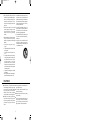
BEFORE USE
Notes on the Compact Disc (CD)
The surface which is glossy like a ralnbow is the front side of the CD, and the surface where the label
information is printed is the back side.
Unlike conventional analog disk turntables, the CD player reads information from the disc by applying laser
beam, in place of a stylus, on the front surface. Consequently, the performance of CD discs will not degrade
after repeated use like conventional analog disks.
■Handle the CD disc carefully so as not to damage the front surface.
■To maintain the CD disc flawless, do not place it in the following locations.
●In a place subject to direct sunlight or near a heat source such as a room heater.
●In a place subject to excessive moisture or dirt.
●In a place which may be subject to rain, for example near a window.
■Keep the disc surface always clean.
UP to about 6 billion items of data are recorded on the Cd disc surface. When cleaning the disc surface,
always use a specialized CD cleaner product and wipe in the direction as shown below.
●Wipe in the radial direction.
●Do not wipe in the circumference direction.
●Never use record cleaner designed for conventional analog disks, for this may degrade the CD disc surface.
■Always store disc properly in the case.
FUNCTIONS
CD SECTION
MIXER SECTION
5
CDX-15/E 00.9.12 7:43 PM ページ 6
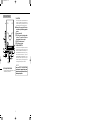
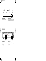
CD SECTION
①CUE BUTTON
The last pause position is always memorised and can
be called up by pressing cue button. This function is
useful for instant cueing, the same position can be
recalled and played back with a single quick action.
■Memory of the cue point will be lost or
reset when any of the following operations
are done.
[1] Power is turned off.
[2]The CD is paused and played another
position. This position will then be
memorised as the new cue point.
[3]The STOP button is pressed.
[4]The CD cover is opened.
4
9
②PLAY/PAUSE BUTTON
This button is used to start and pause the CD. When
the CD is left in pause mode for more than ten
minutes, the CD mechanism is automatically set to
STANDBY MODE and the CD stops spinning.
When the PLAY/PAUSE button is pressed in
STANDBY MODE, the CD mechanism is reset to
PAUSE mode at the last CUE point if the cue point
has been set previously, or at the starting position of
the first song if the cue point has not been set.
11
10
8
6
3
5
1
7 2
NOTE
When the CDX-15 is set to PAUSE with
monitor mode on, it generates the loop sound
between the paused position and four frames
before the paused position.
④PITCH ADJUSTMENT FADER
Used to adjust the play back pitch (speed) by +/-10%
to match the tempo of the music.
6
CDX-15/E 00.9.12 7:43 PM ページ 7
⑤STICK CONTROLLER
The following three functions can be controlled with STICK CONTROLLER,
[1] Pitch bend function
The play back speed can be increased or decreased momentary by moving the STICK CONTROLLER up or
down. When the stick is set to centre position, the CDX-15 plays back at the pitch set by (4) PITCH
ADJUSTMENT FADER. This unique function allows DJs to synchronise the music or adjust the tempo
smoothly.
stick up → The pitch (speed) decreases down to -20%
stick down → The pitch (speed) increases up to +20%
NOTE
The adjustable range of the STICK CONTROLLER is +/-20% regardless the position of ④ PITCH
ADJUSTMENT FADER.
[2] Scan function
When the STICK CONTROLLER is moved to the left or right on PLAY BACK mode, the CDX-15 scans back
or forward at 4 to 10 times (dependant on the angle) of the normal speed. It is used for searching for an
approximate position to play back from.
stick left → Scans backwards.
stick right → Scans forward.
[3] Search function
The stick is moved left or right to search in 1-75 farme units is in PAUSE mode or MONITOR mode.
stick left → Scans backward.
stick right → Scans forward.
■The data on a CD is written at 75 frames per second.
⑥NEXT BUTTON
⑦PREVIOUS BUTTON
Used for skipping forward to the starting point of the
next track. The number of times pressed determines
the number of tracks skipped ahead.
Used for skipping backwards to the starting point of
the current track (one press). Pressing twice returns
to the starting point of the previous track. Pressing
additional times will return to the corresponding
previous tracks.
7
CDX-15/E 00.9.12 7:43 PM ページ 8
⑧DISPLAY BUTTON
Pressing this button each time, the display changes the mode to the following figures.
[1] Time Indication Mode
●CD WITH TEXT DATA
When the DISPLAY BUTTON is pressed, the display mode changes from Total Remain Time to Track Time,
then to Total Remain Time. When the button is pressed one more time from Total Remain Time, the mode is
changed back to text Indication Mode.
Track Remain Time
Track Time
Total Remain Time
《Text Indication Mode》
●CD WITHOUT TEXT DATA
When the CD has no text data, the display mode changes through only three modes, Track Remain Time, Track
Time and Total Remain Time.
Track Remain Time
Track Time
Total Remain Time
[2] Text Indication Mode
In Text Indication Mode, the LCD display shows the album information when the CD is in STOP or track
information in PLAY or PAUSE. The information changes to the next (Track Title > Track Artist > Track
Songwriter, etc.) every time the DISPLAY BUTTON is pressed. After the last information, the display mode
returns to Track Remain Time.
TRACK information ( in PLAY / PAUSE Mode )
Information
Indication on display
Track Tittle
↓
Track Artist
↓
Track Songwriter
↓
Track Composer
↓
Track Arranger
↓
Track Message
↓
《 Track Remain Time》
“Track Title”
Album information ( in STOP Mode )
Information
Indication on display
Album Tittle
“album Title”
↓
Album Artist
“Performer”
↓
Album Songwriter
“Songwriter”
↓
Album Composer
“Composer”
↓
Album Arranger
“Arranger”
↓
Album Message
“Message”
↓
《 Track Remain Time 》
“Performer”
“Songwriter”
“Composer”
“Arranger”
“Message”
8
CDX-15/E 00.9.12 7:43 PM ページ 9
⑨DISPLAY
Indicates motion status, track numbers, times, frames, texts, shock-proof memory status.
[1] Indications of motion status
Indication on the display
Status Vestax CDX-15 on initial setting
Door Open
The door of CDX-15 is open
TOC Reading
TOC data is being read
No Disc
No CD is placed on the CD tray
TOC Error
TOC data cannot be read (bad quality CD)
Read Error
AUDIO data cannot be read (bad quality CD)
NO Audio Disk
CD has no AUDIO data
[2] TRACK NUMBER,TIME,FRAME
[4]Indication of shock proof memory status
The amount of the data in the shock-proof memory is
shown as the fig.
TRACK NUMBER
TIME
FRAME
[3]TEXT
■The shock-proof memory data will be
cleared when any of the following
operations are done.
●STOP BUTTON is pressed
●The DOOR is opened
●FF/REW function is activated
●Search function is activated
●Setting MONITOR ON in PAUSE mode
The CDX-15 only stores the data into
shock-proof memory in PLAY mode or
PAUSE mode with MONITOR SWITCH off.
⑩STOP BUTTON
Used to stop the CD spinning.
⑪REPEAT BUTTON
Used to activate REPEAT mode. All Repeat (play the next song and then repeat the whole CD) is selected by
pressing this button once. Single Repeat (repeat current song only) is selected by pressing one more time.
Repeat Off is selected by one more push, followed by All Repeat with another push.
All Repeat
Single Repeat
9
Repeat Off
CDX-15/E 00.9.12 7:44 PM ページ 10
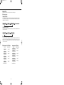
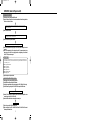
MIXER SECTION
⑫LEVEL VOLUME (PGM A, PGM B)
Used to adjust the input level of each program.
⑬INPUT LEVEL METER
The LED level meters indicate the input signal level
of each PGM channel.
Please adjust the input level so that 0dB LED lights
on peak.
⑭CROSSFADER
The signal of PGM1 can be monitored when the
cross fader is set to the left side. The signal of PGM2
can be monitored when the cross fader is set to the
right side . When the cross fader is set in the middle,
both programs can be monitored.
The cross fader of the CDX-15 is a user-replaceable
fader for ease of replacement. When the cross fader
is worn out, please replace it with the optional
replacement fader, CF-R.
15
13
How to replace the fader
●Remove
the fader knob and four
screws securing the fader panel.
●Remove the fader unit.
●Remove the multi-cable connector
from the fader unit carefully.
●Insert the multi-cable connector to the
new fader unit.
●Place the fader unit and secure it with
four screws.
12
14
⑮MONITOR SELECT SWITCH
Used to select the program channel for headphone
monitoring. The signal of the selected PGM channel
can be monitored from the left side of the
headphones. The signal being output can be
monitored from the right side. In the centre position,
MIX is selected, the master signal can be monitored
in stereo.
10
Remore the multi cable
connector from fader unit.
Remore
four screws
CDX-15/E 00.9.12 7:44 PM ページ 11
17 16
⑰HEADPHONE JACK
⑯HEADPHONE LEVEL
Connect the headphones to this jack. Headphones
with its impedance from 8 ohm to 600 ohm can be
used.
Adjusts the headphone output level.
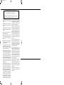
REAR PANEL
MIX
CD
B
OUT
L
L
OUT
A
L
MODEL NO.CDX-15
230V∼50Hz 20W
POWER
CATUTION :SHOCK HAZARD, DO NOT
ON OFF
REMOVE SCREWS.
ATTENTION :RISQUE DE CHOC ELECTRI AUE,
R
R
NE PAS ENLEVER LES VIS.
R
SERIAL NO.
19 20
21
18
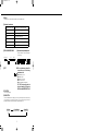
⑳CD OUT JACK
⑱POWER SWITCH
Please ensure that the volume level of the power
amplifier is at minimum position when the POWER
SWITCH is turned on or off.
⑲MIX OUT JACK
The output jack for the play back signal of each CD.
Any of the mixer functions do not effect the signal
from this jack.
21 AC CORD
⃝
Connect to the input of a power amplifier.
11
CDX-15/E 00.9.12 7:44 PM ページ 12
CONNECTION EXAMPLE
Using the mixer equipped with CDX-15
Using the other mixer
MONITOR SPEAKER
MONITOR SPEAKER
DJ MIXER[Vestax PMC-25]
Connect to P
Amplifire etc
POWER AMPLIFIRE
[Vesatx PT-X1000A]
CHANNEL A
MINI
MAX
CHANNEL B
MINI
MAX
PROTECT
B.T.L
POWER
PEAK
PEAK
POWER
INPUT
INPUT
ON / OFF
UNBALANCED INPUT
PGM1
LINE INPUT
PGM2
LINE INPUT
CD OUT B
MIX OUT
CD OUT A
MIX
CD
B
OUT
OUT
A
L
L
L
R
R
R
MODEL NO.CDX-15
230V∼50Hz 20W
POWER
CATUTION :SHOCK HAZARD, DO NOT
REMOVE SCREWS.
ATTENTION :RISQUE DE CHOC ELECTRI AUE,
NE PAS ENLEVER LES VIS.
SERIAL NO.
12
ON OFF
CDX-15/E 00.9.12 7:44 PM ページ 13
OPERATION (Same for Player A and B)
NORMAL PLAYBACK
[1] Turn the power on by pressing the POWER switch.
[2] Open the CD door and place the disc into the centre shaft until the ball chucking holds the
CD with a click. Close the CD door.
CD disc starts spinning and the laser pick-up reads the table of contents. Then pauses at the
beginning of the first track.
[3] Press PLAY/PAUSE button.
Starts playback from the first track immediately. Remaining time of the playing track will be shown
on the digital display in minutes, seconds and frames.
[4] Press NEXT button to skip to the next track.
Stop playing current track and starts playing back from the beginning of next track.
[5] Press PLAY/PAUSE button to stop playback. Press PLAY/PAUSE button again to re-start
playback.
[6] Press STOP button when the CD is not played for a while. This prevents the laser pick up
from wearing out. The CDX-15 starts playing back from the beginning of the track when
PLAY BUTTON is pressed once again.
STANDBY MODE
In case the player is kept in PAUSE mode for over ten minutes, the CDX-15 stops spinning automatically and is set
to STANDBY MODE in order to protect the CD mechanism from wearing out. STANDBY MODE is cancelled if
any of the following is done.
●Pressing PLAY/PAUSE button.
●Pressing CUE button.
●Pressing STOP button.
●Pressing NEXT button.
●Pressing PREVIOUS button.
●Opening the top door.
[7] Open the top door and pull out the disc.
BASIC OPERATION FOR DJ PLAY
[1] Start to play back by pressing PLAY/PAUSE button.
[2] Set MONITOR mode by pressing MONITOR button.
[3] Search for the approximate position to start by moving the STICK CONTROLLER left or right.
[4] Set PAUSE mode by pressing PLAY/PAUSE BUTTON and press MONITOR button.
Repeat sound of pause point can be monitored in 4 frame cycles.
[5] Now the STICK CONTROLLER is set to the SEARCH mode.The exact start position can be
searched by moving the STICK CONTROLLER.
[6] Press MONITOR button after the start position is accurately set.
Repeat sounds stops.
[7] Play back by pressing PLAY/PAUSE button again.
[8] Adjust the pitch by using PITCH CONTROL FADER and STICK CONTROLLER to match
the tempo with the other music.
13
CDX-15/E 00.9.12 7:44 PM ページ 14
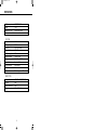
SPECIFICATIONS
Total Power requirement
Weight
Dimensions (W+H+D)
Accessory
115V/230V AC, 20W
7.5kg
442(W)+289(W)+890(H)
owners manual
CD SECTION
Quantization:
Sampling Frequency
Digital Filter
Shock Proof Memory
Error Correcting System
Harmonic Distortion
Frequency response
Signal To Noise Ratio
Channel Separation
CD OUT
Mechanism Mount:
16bit linear
44.1kHz
8 times over sampling
16Mbit, 10sec
CIRC
Less than 0.008%
20Hz 20KHz =81}1.5dB
More than 96dB
More than 85dB
2Vrms
Ball chucking top mount CD mechanism
MIXER SECTION
Frequency Response
Cross Talk
Signal To Noise Ratio
Headphone Level
20Hz~20kHz =81}2dB (MIX OUT)
60dB
90dB
1.2Vrms (33(c) Load)
14
CDX-15/E 00.9.12 7:44 PM ページ 15
Vestax Corporation