1
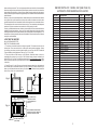
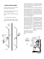
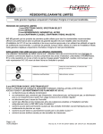
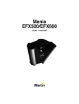
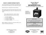
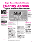
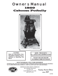
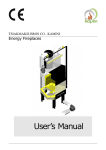
OWNERS MANUAL
Model 2941
HOW TO ORDER REPAIR PARTS
This manual will help you to obtain efficient, dependable service
from the heater, and enable you to order repair parts correctly.
WONDERWOOD
THERMOSTAT CONTROLLED WOOD BURNING CIRCULATOR
Keep this manual in a safe place for future reference.
When writing, always give the full model number which is on the
nameplate attached to the inside of the cabinet door of the
heater.
When ordering repair parts or options, always
give the following information as shown in this list:
1.
2.
3.
4.
WONDER
W OOD
*ASSEMBLY
*INSTALLATION
*OPERATION
*REPAIR PARTS
The PART NUMBER
The PART DESCRIPTION
The MODEL NUMBER: 2941
The SERIAL NUMBER:________________
SAFETY NOTICE:
If this heater is not properly installed, a house fire may result.
For your safety, follow the installation directions.
Contact local building or fire officials about restrictions and
inspection requirements in your area.
Before installing your heater, fill in the serial number of your
heater in the space provided above.
CAUTION:
Read all instructions carefully before starting the installation
or operation of this heater.
Improper installation may void your warranty.
DO NOT USE THIS HEATER IN A MOBILE HOME OR TRAILER
Tested to UL 1482 & CAN/ULC-S627
STATES STO
TED
V
NI
USSC
COMPANY
E
227 Industrial Park Rd.
P.O.Box 151
South Pittsburg, TN 37380
(423) 837-2100
www.USSTOVE.com
United States Stove Company
U
United States Stove Company
227 Industrial Park Rd.
P.O.Box 151
South Pittsburg, TN 37380
(423) 837-2100
www.USSTOVE.com
85947-J
TOOLS AND MATERIAL NEEDED
TOOLS
Pencil
6 Foot Folding rule or tape
Tin Snips
Drill, hand or electric
Drill bit, 1/8" dia.
(for sheet metal screws)
Gloves
Screwdriver (blade-type)
5/16" Nut Driver or
5/16" Socket w/Ratchet
F36 BLOWER KIT
MATERIALS
Chimney Connection- 6" Dia. Black
Steel (24 Ga. minimum): Straight or
corrugated elbow (as required)*
1/2" Sheet Metal Screws
6" Inside Diameter Underwriters
Laboratories (UL) listed Residential
Type and Building Heating Appliance
Chimney, Type "HT", or 6" existing
Masonry Chimney with flue liner.
Floor Protector Material: 3' x 4'-6" as
specified on page 4.
Furnace Cement (Manufacturer
recommends: Rutland Code 78 or
Equivalent)
* Avoid adjustable elbows, they leak!
An Optional Blower kit is available for the 2941 Wonderwood
automatic wood burning circulator heater. If this kit is not available
where you have purchased this Wonderwood heater, you can
purchase the F36 Blower Kit directly from the factory. To order
contact the United States Stove Company at the address and
telephone number given on the back page.
CIRCULATOR DIMENSIONS
Fig. 1
19 1/4
32 1/4
12 1/2
CENTER LINE OF 6"
CHIMNEY CONNECTOR
4 1/4
CENTER LINE
OF 6"
CHIMNEY
CONNECTOR
WONDERWOOD
33 1/2
24
4 1/8
TOP OF FLOOR PROTECTOR
RULES FOR SAFE INSTALLATION AND OPERATION
Read these rules and the instructions carefully.
SAFETY NOTICE: If this heater is not properly installed, a house fire may result. For
your safety, follow the installation directions. Contact local building or fire officials
about restrictions and installation inspection requirements in your area.
1. Check local codes. The installation must
comply with their rulings. Do not install this
heater in a mobile home or trailer.
2. Always connect this heater to a chimney or
vent to the outside. Never vent to another
room or inside a building.
3. Do not connect a WOOD burning heater to
an aluminum Type B gas vent. This is not
safe and is prohibited by all codes. This
heater requires connection to approved
chimneys: Either a factory built 6" UL 103HT
or a lined and approved and recently in
spected and cleaned masonry chimney
with a 6" flue, preferably round. A larger
masonry flue may be used, so long as the
flue-section diameter is not greater than 50
sq. in.
The chimney portion (whether factory-built
2
19
NOTE:
DURING OPENING AND CLOSING OF THE FEED AND ASH DOORS
OF THIS HEATER, IT MAY SEEM THAT THE FIT OF THE DOOR IS
"TOO TIGHT". AS THE HEATER IS FIRED, THE GASKETING
"SETTLES" OR "SEATS" ITSELF IN THE DOOR. THE TIGHT FIT AT
THE FACTORY AND BEFORE THE HEATER'S INITIAL FIRING IS TO
INSURE A GOOD SEAL AFTER THE GASKETING "SETTLES".
NOTE:
FOR YOUR SAFETY, WE RECOMMEND INSTALLING SMOKE
DETECTORS IN YOUR HOME IF NOT ALREADY INSTALLED.
SAFETY NOTICE
In the unlikely event that your 2941 "overfires" (a condition evidenced by elbows,
stovepipes, and connectors glowing red in appearance or otherwise discoloring),
then your installation is subject to excessive draft created by either a chimney too tall
or too great in diameter in conjunction with its height, or some other factor of an
indeterminate cause. In this event, you should install a barometric draft regulator.
Such installation will preclude any overfiring and/or any hazardous consequences
of potential overfiring.
Barometric draft regulators are generally available where you purchased your stove
or may be ordered directly from United States Stove Company at a nominal charge.
2001 Consumer Price:
$24.00 - Includes Shipping and Handling
or masonry) must be tall enough to provide
sufficient draft and safe exit of smoke and
combustion products. Please refer to Page
5.
4. Be sure that your Chimney is safely con
structed and in good repair. Have the chim
ney inspected by the Fire Department or a
qualified inspector (such as a Chimney
sweep). Your insurance company may be
able to recommend a qualified inspector.
5. Inspect chimney connector and chimney
twice monthly during the heating season for
any deposit of creosote or soot which must
be removed.
6. Provide air for combustion from outside the
house into the room where the heater is
located. If the intake is not in the same room,
air must have free access to the room.
7. CAST IRON PARTS MUST BE "SEA
SONED" TO AVOID CRACKING. BUILD
ONLY SMALL FIRES ON FIRST USE.
8. To prevent injury, do not allow anyone to
use this heater who is unfamiliar with the
correct operation of the heater. Do not allow
children to use or in any way operate this
heater.
9. For further information on using your heater
safely, obtain a copy of the National Fire
Protection Association (NFPA) publication
"Using Coal and Wood Stoves Safely" NFPA
No. HS-10-1978. The address of the NFPA
is Battery March Park, Quincy, MA. 02269.
10.Keep the ash pit section free of excess
ashes. Do not allow ashes to stack higher
than the sides of the ash pan.*
11.DISPOSAL OF ASHES- Ashes should be
placed in a metal container with a tight fitting
lid. Keep the closed container on a noncombustible floor or on the ground, well
away from all combustible materials. Keep
the ashes in the closed container until all
cinders have thoroughly cooled. The ashes
may be buried in the ground or used as
fertilizer.
12.CAUTION: The special paints used on your
heater may give off some smoke while they
are curing during first few fires. Build small
fires at first. The metal used in construction
of the heater has a light coating of oil. This
could give off smoke and/or odors when
heater is used for the first couple of times.
This should disappear after a short period.
Once this burn-off has occurred, it should
not reoccur.
13.CARING FOR PAINTED PARTS- This
heater has a painted outside jacket, which is
durable but will not stand rough handling or
abuse. When installing your heater, use
care in handling. Clean with soap and warm
water when heater is not hot. DO NOT use
any harsh chemicals (acids or caustics) or
scouring powder, as these wear and dull the
finish.
14.KEEP THE FEED DOOR, ASH DOOR AND
CABINET DOOR CLOSED AT ALL TIMES
EXCEPT WHILE TENDING THE HEATER.
DO NOT OVERFIRE THE HEATER. THIS
WILL HAPPEN IF THE FEED DOOR, OR
PARTICULARLY THE ASH DOOR, IS LEFT
OPEN DURING OPERATION. UNDER EX
TREME CONDITIONS THIS CAN PRO
DUCE DANGEROUS RESULTS. AT A
MINIMUM, IT WILL ALLOW THE PAINT TO
DISCOLOR.
CAUTION: DO NOT TOUCH THE
HEATER UNTIL IT HAS COOLED.
ALWAYS WEAR GLOVES WHEN
REFUELING THIS UNIT OR WORKING
WITH METAL CABINET PARTS.
* Never allow ashes to contact the grate(s).
MINIMUM CLEARANCES TO COMBUSTIBLE WALLS AND CEILINGS
BAROMETRIC DRAFT REGULATOR
Model DR6
18
Minimum clearances to unprotected combustible walls and ceilings as noted by figures 2 through
4 must be maintained. Drapes, curtains, furniture and other combustible materials should be kept
much further away from the heater to avoid fire. If you choose to, you may install the heater and
chimney connector closer to combustible surfaces than indicated by Figures 2 through 4 IF a
clearance reduction system is also installed to protect combustible ceilings and walls near the
heater and chimney connector. However, there are limits to how close the heater and chimney
connector can be installed to combustible surfaces protected by a clearance reduction system.
A correctly installed clearance reduction system protects the combustible surfaces well beyond
the sides and above the top of the heater and beyond the sides and top of the chimney connector
pipe.
Two common types of clearance reduction systems use sheet metal with a minimum thickness
of 28 gauge (galvanized steel, aluminum, copper) or a 3-1/2 inch (4 inch nominal) thick masonry
wall. Either of these materials must be spaced out 1 inch from the combustible surfaces. With
sheet metal, non-combustible spacers are used to maintain the 1 inch air space. With a masonry
wall, metal wall ties and furring strips, if needed are used to anchor the brick to the wall. To avoid
excessive heat transmission, the spacers or wall ties should not be placed directly behind the
3
heater or chimney connector. The 1 inch air space provides free air circulation. It is essential that
there be openings at the top and bottom of these clearance reducers so cool air can enter at the
bottom and hot air exit at the top. It is the "chimney effect" whereby when the air in the space is
heated, it rises exiting from the top and being replaced by cooler air at the bottom, that makes these
shields effective.
Masonry, or other non-combustible products, attached directly to a combustible surface without
an air space offer very little protection and cannot be considered a clearance reducer unless
specified materials have been tested and listed for direct attachment to a combustible surface.
The same applies to thin veneer brick and stone coverings. These materials provide adequate
protection only when mounted on sheet metal with a 1 inch spacing to the wall.
A variety or prefabricated clearance reduction systems which have been tested and listed are
available through heater dealers. Always look for a safety listing label on the product when
selecting a clearance reduction system and make sure it is designed for solid fuel appliances. The
manufactures of these systems provide specific installation instructions that must be followed
exactly for a safe installation.
LOCATING THE HEATER
AS A LOCATION IS SELECTED,
KEEP THE FOLLOWING IN MIND:
1. The chimney connection should be as airtight as possible. The heater must have its own
chimney flue. Do not connect this unit to a chimney flue serving another appliance. If there
is no chimney near where you wish to place the heater, you can use a UL 103HT Residential
Type and Building Heating Appliance Chimney (Fig. 5, 6, 6A & 6B).
2. Place the heater on solid masonry or solid concrete. When the heater is used on a
combustible floor protector of one layer of 3/8" millboard having a thermal conductivity of
K=0.84 BTU in./ft. 2 hr. Deg. F with 28-gauge sheet metal or a UL Listed floor protector. Have
the floor protector extend 16" beyond the door side of the heater and under the connector pipe
in the back.
3. Check Figures 2, 3, and 4. Be sure you have the clearances shown from the heater and
the connector pipe to combustible surfaces. If you have a solid brick or stone wall behind your
heater, you can place the heater as close as you wish to the wall. If the wall is only faced with
brick or stone, treat it as a combustible wall.
26"
25"
Fig. 2
Fig. 3
WONDERWOOD
35"
16"
12"
REPAIR PARTS LIST - MODEL 2941 (SEE PAGE 18)
AUTOMATIC WOOD BURNING CIRCULATOR
Key No.
1
2
3
*
4
5
6
7
8
9
10
11
12
13
14
15
16
17
18
19
20
21
22
23
24
25
26
27
28
29
30
31
*
Heat Jacket Assembly
Base Weldment
Smoke Curtain
Smoke Curtain Bracket
Flue Collar
Flue Collar Gasket
Draft Damper Frame
Draft Control Damper
Draft Damper Hinge Pin
Clip Spring
Fire Grate
Liner
Firebrick
Top Brick Retainer
Feed Door Assembly
Ash Door Assembly
Feed Door
Ash Door
Door Latch
Door Handle
Feed Door Rope Gasket
Ash Door Rope Gasket
1/4-20 Kep Nut
5/16 ID, 3/4 OD Washer
Latch Spacer
Door Hinge Pin (Short)
Door Hinge Pin (Long)
Heat Shield
Drop Wooden Handle
Ash Pan
Solid Damper
Top Liner
Heat Shield
Secondary Heat Shield
12"
NOT SHOWN
36"
19 1/4"
32 1/4"
16"
17"
SIDEWALL FLOOR PROTECTOR
(TOP VIEW)
NOTE: DASHED LINES SHOW
STRAIGHT UP AND THROUGH
THE WALL INSTALLATION
4 3/4"
4
Qty.
Part No.
1
1
1
2
1
1
1
1
1
1
2
3
10
2
68619
67859
22090
22171
40246
88032
40075
23476
17200
83818
40076
40100
89066
40132
68621
68620
40199
40289
22108
40091
88033
88033
83250
83045
21467
83872
23441
23475
89523
67444
D6
23474
22110
22030
1
1
2
2
3.75FT
2.5FT
2
2
2
1
1
1
1
1
1
1
1
1
NON-COMBUSTIBLE
CONSTRUCTION IN
ACCORDANCE WITH
NFPA 211
54"
Fig. 4
Description
17
of which is apparent: The chimney
provides a means for exhausting smoke
and flue gases resulting from combustion
of the fuel. Secondarily, though, the
chimney provides "Draft" which allows
oxygen to be continuously introduced
into the appliance, so that proper
combustion is possible. As of April 1,
1987, all heaters and furnaces
manufactured by United States Stove
Company should be installed using a
factory built chimney that meets the
"Type HT" requirement of UL 103 (when
a factory - built chimney is used).
CHIMNEY CONNECTION
28
30
31
30
31
9
7
6
8
25
2
27
1
13 12
3
11
10
20
32
24
REPAIR PARTS
AUTOMATIC WOOD BURNING CIRCULATOR HEATER
5
MODEL 2941 - INTERIOR
4
Two basic types of chimneys are approved for use with solid fuel: Factorybuilt and masonry. Factory-built chimney
must comply with UL103HT standard.
Do not expect your stove or furnace to
create draft. Draft is not a function of the
appliance. Draft is purely a function of
the chimney. Modern stoves and
furnaces are much more air-tight and
efficient than those of the past and,
therefore require greater draft. A
minimum of .05, measured in water
column (gauges to measure chimney
draft are readily available at stove shops
and are economical to purchase or rent)
is required for proper drafting to prevent
back-puffing, smoke spillage, and to
maximize performance.
IMPORTANT
*Size the chimney to the flue outlet on
the stove. (6" outlet = 6" I.D. chimney)
*Avoid using elbows except as
necessary (they reduce draft).
*Make sure all horizontal runs of connector pipe go up hill (1/4" elevation for
each horizontal foot).
Chimneys perform two functions - one
CHIMNEY CAP MANDATORY
CHIMNEY CAP MANDATORY
2 FT MIN.
2 FT MIN.
3 FT.
MIN.
10 FT.
11 FT. MIN.
3 FT.
MIN.
10 FT.
11 FT. MIN.
REFER TO CHIMNEY
MANUFACTURERS PARTS
AND INSTRUCTIONS
REFER TO CHIMNEY
MANUFACTURERS PARTS
AND INSTRUCTIONS
PIPE
17
17
16
21 22
23
14 18
15
19
PIPE
DAMPER
DAMPER
BAROMETRIC
DRAFT CONTROL
(OPTIONAL)
BAROMETRIC
DRAFT CONTROL
(OPTIONAL)
29
20
16
22
26
21
FLOOR PROTECTOR
FLOOR PROTECTOR
FIG. 6
Cathedral Ceiling - Chimney
Cap Mandatory
FIG. 5
16
5
FIG. 6A - Thru-The-Wall Installation
REPAIR PARTS
AUTOMATIC WOOD BURNING CIRCULATOR HEATER
MODEL NUMBER 2941
(SEE PAGE 16)
NON-COMBUSTIBLE
WALL
THIMBLE
COLLAR
PIPE
REPAIR PARTS LIST
DAMPER
BAROMETRIC
DRAFT CONTROL
(OPTIONAL)
FLOOR PROTECTOR
CLASS A UL 103HT
CHIMNEY KIT INCLUDING
WALL THIMBLE.
FIG. 6B - Typical Masonry Chimney Installation
APPROVED COWL
2 FT MIN.
10 FT.
MINIMUM
6" MIN.
3 FT.
MIN.
APPROVED
THIMBLE
60" MIN.
DAMPER
BAROMETRIC DRAFT
CONTROL
6"
MIN.
KEY NO. PART NO.
1
89062
2
83005
3
83033
4
83093
5
83244
6
67968
7
86191
8
85381W
9
89142
10
67725
11
67967
12
21593
13
83833
14
67966
15
67743
16
21063
17
67514
18
89065
19
67969
20
23477
21
83406
DESCRIPTION
Cabinet Door Knob
Screw (10-24 x 1/2) FL
Screw (8-32 x 1/4) PH,TR,HD,Z
Spring Latch
Kep Nut (10-24)
Cabinet Door Frame
Thermostat Linkage
Control Panel Plate
Thermostat Knob
Cabinet Front Assembly
Cabinet Left Side
Hinge Support
Hinge Clip
Cabinet Top
Thermostat Assembly
Back Brace
Cabinet Back
Door Hinge
Cabinet Door
Top Thermostat Shield
10-16 x 3/4 TORX, WAF, HD,DP,Z
FLOOR PROTECTOR
6
15
QTY.
1
1
1
1
1
1
1
1
1
1
1
1
1
1
1
2
1
4
1
1
2
VENTING INTO A FIREPLACE
(Not recommended)
8
REPAIR PARTS
AUTOMATIC WOOD BURNING CIRCULATOR HEATER
MODEL 2941 - EXTERIOR
Many prefabricated fireplaces fall into
the "zero-clearance fireplace" category.
This is a factory metal fireplace with
multi-layered construction. It is designed
to provide enough insulation and/or air
cooling so that the base, back and sides
can be safely placed in close contact
with combustible floors and walls. Although many prefabricated fireplaces
have been tested by nationally recognized organizations for use as fireplaces, they have not been tested to
accept heaters. In fact, their use as such
may void the manufacturer's warranty.
Many people may wish to convert an
existing fireplace to heater use. Usually,
safe connection of stovepipe to a masonry chimney requires more effort than
connection to a prefabricated chimney.
The fireplace must be closed and sealed
at the damper in the flue. Good sealants
are high temperature caulking, ceramic
wool, and furnace cement. Always remember to inspect the masonry chimney and fireplace. If necessary, clean
the flue and smoke shelf before beginning your installation. Install the heater
into the chimney so that the system can
be dismantled for cleaning and inspection.
12
13
11
WO
N
DE
RW
OO
D
9
10
21
7
Steel-lined fireplaces, on the other
hand, can be used with heaters. These
units use a 1/4-inch fire box liner and an
air chamber in connection with 8 inches
of masonry to meet code. They contain
all the essential parts of a fireplace,
firebox, damper, throat, smoke shelf,
and smoke chamber. Many of them look
exactly like a masonry fireplace and
must be checked closely for above requirements before installing a coal
heater into them.
16
15
14
6
Before deciding to convert your fireplace or existing chimney, keep in mind
that older fireplaces and their chimneys
are unsafe. They must be structurally
sound, and the flue liner must be in good
condition. Do not use a chimney if it is
unlined (should have a tile clay liner
to protect brickwork), have it relined
professionally. Clearances to combustibles are explained in the previous section on masonry chimneys. If you have
any questions regarding the condition
of the chimney, consult a qualified engineer, competent mason, certified Chimney Sweep, or knowledgeable inspector.
17
Another method frequently used by
some people is to vent the heater directly into the fireplace. This does not
meet code since the heater is being
vented into another appliance - the
fireplace. This method should not be
attempted because combustion products will deposit and build up in the
firebox or fireplace. Be certain not to
install a hazard in you house. You will
void your warranty with this installation.
18
5
19
4
3
2
1
14
CAUTION:
NOT ALL FIREPLACES
ARE SUITABLE FOR
INSTALLATION OF A WOOD
HEATER.
7
SERVICE HINTS
FIREPLACE INSTALLATION
Connection of the stovepipe directly into
the existing masonry chimney over the
fireplace opening is the only approved
method. This installation performs better, yielding easy to clean and inspect
for creosote. Before beginning this type
of installation plan carefully; a high degree of skill is required to insure safety.
Install the stovepipe as far as possible
into the thimble, but not past the inside
of the flue lining. There should be a
small air space (approximately 1/2 in.)
between the stovepipe and thimble, allowing for expansion of the stovepipe.
Seal this airspace with high-temperature caulking or ceramic wool. Finally,
be sure to wire the damper closed and
apply the same sealant you used at the
stovepipe and thimble junction.
An entry port for the stovepipe must be
cut through the chimney with minimum
damage to the fire clay liner. Some
involved measurements may be required
to locate the flue liner exactly. Before
cutting, take time to mark the size and
position of the entry port. Position the
entry port so that at least 8 inches of the
flue liner remains below the port.
Do not vent up through the fireplace
opening, regardless of whether the fireplace opening is closed.
MASONRY CHIMNEY have several
positive attributes: If properly built, they
are quite durable, and most homeowners
consider them more attractive perhaps
than a non-enclosed factory built
chimney. And, if the chimney is located
within the confines of the house (that is,
not attached to an exterior wall), its
mass alone will store heat longer and
continue to release the heat long after
the fire has died. Masonry chimneys
have many disadvantages though.
Keep in mind that wood mantels and
combustible trim around the fireplace
must have adequate clearances from
the heater and stovepipe or must be
protected in an approved manner. Also,
be sure to leave at least 24" clearance
between the top of the stovepipe and
the combustible ceiling or other combustibles. Placing the center of the entry
port 2 feet below the ceiling will insure
proper clearance for 6 inch, 8 inch, and
10 inch stovepipes. Next, install a fire
clay (at least 5/8 in. thick) or metal
thimble, being sure that the thimble is
flush with the inner flue lining. Secure
the thimble in place with refractory mortar. The thimble should be surrounded
on all sides with 8 inches of brickwork
(solid masonry units) or 24 inches of
stone.
Masonry chimneys constructed on an
exterior wall are exposed to cold outdoor temperatures, promoting greater
heater loss, higher accumulations of
creosote, and reduced draft which leads
to poorer heater or furnace performance.
Do not expect a heater to draw. It is the
chimney that creates the draft. Smoke
spillage into the house or excessive
build-up of water or creosote in the
chimney are warnings that the chimney
is not functioning properly. Possible
causes are:
1. The connection pipe may be pushed
into the chimney too far, stopping the
draft (Fig. 8).
2. Two heaters connected into the
same chimney flue.
3. Same flue being used to ventilate the
cellar or basement. If there is a cleanout
opening at the base of the chimney, it
must be closed tightly and sealed.
4. If the chimney is too cool, water will
condense in the chimney and run back
into the stove. Creosote formation will
be rapid and may block the chimney.
Operate the heater at a high enough fire
to keep the chimney warm preventing
this condensation. (Poorly insulated
chimney)
5. The chimney top may be lower than
another part of the house or a nearby
tree. The wind blowing over a house or
a tree falls on top of the chimney like
water over a dam, beating down the
smoke. The top of the chimney should
be at least 3 feet higher than any point
of the roof within 10 feet (Fig. 6).
6. Other chimney/flue inadequacies
covered else where in this manual.
NOTE:
A draft reading of .05 to .06 w.c. is suggested for proper burning of this
unit.
CHIMNEY MAINTENANCE
CREOSOTE-FORMATION AND NEED FOR REMOVAL
When wood is burned slowly, it produces tar and other organic vapors,
which combine with expelled moisture
to form creosote. The creosote vapors
condense in the relatively cool chimney
flue of a slow burning fire. As a result,
creosote residue accumulates on the
flue lining. When ignited, this creosote
makes an extremely hot fire.
The chimney connector and chimney
should be inspected at least twice
monthly during the heating season to
determine if a creosote build-up has
occurred.
If creosote has accumulated, it should
be removed.
Failure to remove creosote or soot may
cause a house fire. Creosote may be
removed by using a chimney brush or
other commonly available materials. Or,
better yet, by a certified chimney sweep.
Chimney fires burn very hot. If the chimney connector should glow red, immediately call the fire department, then reduce the fire by closing the inlet air
control and closing the damper in the
pipe.
CAUTION
A chimney fire may cause ignition of wall studs or rafters which you
thought were safe distance from the chimney. If you have a chimney fire,
have your chimney inspected by a qualified person before using again.
8
13
CABINET DOOR KNOB ASSEMBLY
The door knob is mounted inside of the cabinet door to facilitate
shipping and must be reversed for proper usage.
To get cabinet door open, place hand under cabinet frame (right
hand side of cabinet door) and push door out.
INSTALL THE CABINET DOOR KNOB USING THE STEPS
BELOW:
1. Remove the machine screw and door knob (Fig. 10).
2. Place door knob on outside of cabinet door. Then place
machine screw through hole and into door knob and tighten (Fig.
11).
MACHINE
SCREW
When considering a masonry chimney,
round tiles are preferable to square or
rectangular, as round tiles have much
better airflow characteristics and are far
easier to clean. Unfortunately, most
North American chimneys use square or
rectangular tile liners that are really designed for open fireplaces, not stoves or
furnaces. Of most importance, second
only to overall chimney height, is the
diameter of the flue liner itself. In most
instances, it should be sized to the appliance; i.e., 6" flue outlet on the appliance
requires a 6" flue. The inner diameter
should never be less than the flue outlet
diameter and should never be greater
than 50% of the appliance flue outlet. For
example, do not expect a wood burning
stove or furnace to function properly if
installed into a chimney with a flue liner
greater than 50% the appliance outlet - such as a 6" flue outlet requires a 6"
diameter for optimum drafting, but can
function well with an 8", but becomes
borderline beyond 8" diameter.
solid fuel appliance must not be joined
to a chimney flue which is connected to
another appliance burning other fuels.
If your chimney has a typically oversized
flue liner of 8x12 inches or greater, or if it
is unlined, it will be necessary for you to
reline the chimney, using many of the
modern approved and economical methods such as stainless steel, castable
refractory, or properly sized fireclay linings.
If you have any question regarding venting
your appliance, feel free to contact the
factory at the address and phone number
on this Owner's Manual. You may also
contact NFPA (National Fire Protection
Association) and request NFPA Standard
211 (1984 Edition). Their address is
Battery March Park, Quincy,
Massachusetts 02269. Another helpful
publication is NFPA Standard 908,
available at the same address. Specify
1984 Edition on either of the above
publications.
Masonry chimneys built of concrete
blocks without flue liners of at least 5/8"
fireclay do not meet modern building
codes. A
CABINET DOOR
KNOB
TYPE "A"
FIREPLACE
CONVERSION
Fig. 7
STOVEPIPE CONNECTOR
SEALED AT THIMBLE
5/8" FIRECLAY
FLUE LINER
HORIZONTAL 6" STOVEPIPE
(24 GAUGE) WITH 1/4"
RISE PER FOOT
6" STOVEPIPE ELBOW
CLEARANCE REDUCER
(FOR MANTEL)
6" STOVEPIPE - HAVING
THREE SHEET METAL SCREWS
PER JOINT OF STOVEPIPE
Fig. 10
Fig. 11
U.L. LISTED
FLOOR PROTECTOR
12
9
DAMPER THROAT
CLOSED AND SEALED
RULES FOR CONNECTOR PIPE INSTALLATION
1. The crimped end of the stovepipe fits
inside the heater flue collar. Install additional pipe and elbow with the
CRIMPED END TOWARD THE
HEATER. This will allow any
condensation in the flue to run back into
the heater. Smoke will not escape when
installed in this manner.
5. Seal each connector pipe joint with
furnace cement. Also seal the pipe at
the chimney.
6. Use 3 Sheet Metal screws at each
joint to make the piping rigid.
7. It is recommended that no more than
two 90 degree bends be used in the
stovepipe installation as more than two
may decrease the amount of draw and
if possible, use only corrugated (nonadjustable) elbows. They are much more
airtight.
2. Slope any horizontal pipe upward
toward the chimney at least 1/4 inch for
each foot of horizontal run.
3. You must have at least 18 inches of
clearance between any horizontal piping and the ceiling.
8. The chimney connector must not
pass through an attic or roof space,
closet, or any concealed space, or floor,
ceiling, wall or combustive construction.
4. The pipe cannot extend into the
chimney flue. (Fig. 8)
RIGHT
WRONG
WRONG
Fig. 8
HOW TO LIFT THE TOP
CAUTION - DO NOT OPEN OR CLOSE TOP WHEN HEATER IS HOT!
To open, grasp TOP at front and lift all the way, then gently lower the TOP
until the TOP SUPPORT ROD latches to hold the TOP (Fig. A).
To close, lift TOP until the TOP SUPPORT ROD is unlatched. Pull the ROD
forward and lower the TOP (Fig. B).
GRASP TOP
HERE TO
OPEN
SUPPORT ROD
TOP
SUPPORT
SEAT
WONDE
WONDE
RWOOD
A
RWOOD
B
Fig. 9
10
OPERATING INSTRUCTIONS
FUEL
Hardwood, 18" to 23" should be split
and air dried (seasoned) for 6 months to
obtain maximum burning efficiency.
Wood should be stored in a dry, well
ventilated area. A Wooden box or crate
is ideal for storage.
NOTE: USE SOLID WOOD MATERIAL
ONLY. DO NOT USE COAL.
DO NOT USE MANUFACTURED OR
CHARCOAL LOGS!
LIGHTING
1. Set the thermostat on "High" for
maximum draft.
2. Open the feed door and place paper
and kindling on the grate for starting the
fire.
3. Light fire and close feed door.
4. Add fuel after fire is burning briskly.
Use care not to smother the kindling fire.
5. Set thermostat higher or lower for
desired temperature.
ADDING FUEL
When possible, add small amounts of
fuel each hour or so instead of adding
large quantities of fresh fuel every 4 to
5 hours. This will give more complete
combustion and less build-up of tars or
soot in the chimney.
1. Set Thermostat to HIGH before opening feed door.
2. Empty ash pan regularly. Do not
allow ashes to build up to grate as grate
will warp and burnout will occur, and
you might spill the ashes when removing the pan. Dispose of hot ashes properly (see Note 11 on Page 3).
CAUTION:
HOT WHILE IN OPERATION.
KEEP CHILDREN, CLOTHING
AND FURNITURE AWAY.
CONTACT MAY CAUSE
SKIN BURNS.
11
CAUTION: BUILD A FIRE ON THE
INTEGRAL GRATE THAT IS PROVIDED WITH THE HEATER.
CAUTION: STORING OF WOOD
WITHIN MINIMUM CLEARANCES OF
HEATER MAY CAUSE HOUSE FIRE.
CAUTION: DO NOT OVERFIRE THE
HEATER, AS STATED EARLIER, THIS
CAN PRODUCE A DANGEROUS
CONDITION AND EVEN CAUSE A
HOUSE FIRE. IF ANY PORTION OF
THE HEATER OR ANY CHIMNEY
CONNECTOR GLOWS RED OR DISCOLORS, THE HEATER IS BEING
OVERFIRED.
CAUTION: DO NOT OPERATE THIS
HEATER WITH FEED OR ASH DOOR
OPEN. THIS HEATER IS DESIGNED
FOR THERMOSTATIC OPERATION.
OPERATION WITH EITHER DOOR
OPEN WILL OVERHEAT AND DAMAGE THE HEATER.
CAUTION: NEVER STORE FLAMMABLE LIQUIDS, ESPECIALLY
GASOLINE, IN THE VICINITY OF THE
HEATER.
CAUTION: NEVER USE GASOLINE,
GASOLINE-TYPE LANTERN FUEL,
KEROSENE, CHARCOAL LIGHTER
FLUID, OR SIMILAR LIQUIDS TO
START OR "FRESHEN UP" A FIRE IN
THE HEATER.
DO NOT BURN GARBAGE OR FLAMMABLE FLUIDS.
DO NOT CONNECT TO ANY AIR
DISTRIBUTION DUCT OR SYSTEM.
NOTE: BEFORE FIRING
HEATER
1. Remove plastic knob from
inside of cabinet door and
install on outside of door.
(See Page 15)
2. Slide firebricks toward the
rear so no gaps remain
between them.