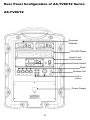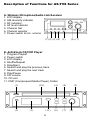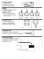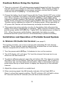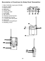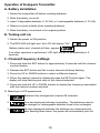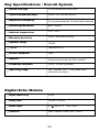
1
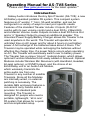
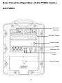
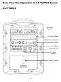
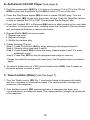
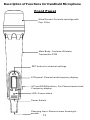
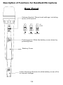
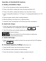
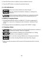
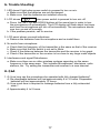
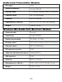
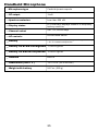
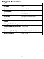
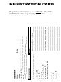
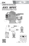
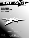
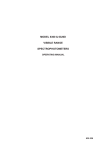
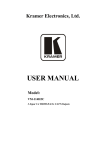
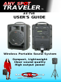
ANY SP
OT
SPOT
®
TRAVELER
TM
AS-TV8
USER'S GUIDE
Wireless Portable Sound System
Compact, Lightweight
Clear sound quality
High output power
®
Contents
Operating Manual for AS-TV8 Series..................................................... 1
Front Panel Configuration of AS-TV8 Series..........................................2
Rear Panel Configuration of AS-TV8 Series ..........................................3
Description of Functions of AS-TV8 Series...........................................6
Caution Before Using the System..........................................................9
Installation and Operation of Portable Sound System............................9
Wireless Mic/Receiver Audio Link..........................................................9
Anti Shock CD/CMP Player...................................................................10
Tone Controls........................................................................................10
In/Out Jacks..........................................................................................11
Speaker Out..........................................................................................11
Digital Echo System..............................................................................11
Audio Link Transmitter..........................................................................11
Description of Functions for Handheld Microphone Front....................13
Description of Functions for Handheld Microphone Back.....................14
Operation of Handheld Microphone......................................................15
Description of Functions for Body Pack Transmitter.............................18
Operation of Body Pack Transmitter.....................................................19
Maintenance.........................................................................................21
Specifications..................................................................................22-26
Key Specs/Overall System...................................................................23
Digital Echo Module..............................................................................23
Audio Link Transmitter Module.............................................................24
Receiver Module...................................................................................24
Handheld Microphone..........................................................................25
Bodypack Transmitter...........................................................................26
Operating Manual for AS-TV8 Series
**Please visit www.galaxyaudio.com for the latest updates**
Introduction
Galaxy Audio introduces the Any Spot Traveler (AS-TV8); a new
AC/battery operated portable PA system. This compact system
features an 8” woofer, 1” horn, 50-watt amplifier, and can be
configured in a variety of ways to meet your specific needs.
Features of the standard Traveler include: 2 Inputs (XLR/1/4”
combo with its own volume control and a dual RCA), 2 Band EQ,
and a Master Volume. Audio Outputs include a dual RCA Line Out
and a ¼” Speaker Output to power an additional speaker. The
Universal Power Supply/Battery Charger allows the Traveler to be
used anywhere in the world. The Traveler will operate for an
unlimited time on AC power and for about 6 hours on just battery
power. A full recharge of the batteries takes about 4 hours. The
Traveler may be operated while recharging the batteries without
affecting the charge time. If a power failure occurs when operating
on AC, the Traveler will seamlessly switch over to battery power.
The Traveler has a unique “plug in” modular design, which allows
optional Function Modules to be easily added or removed. Optional
Modules include Wireless Mic Receivers (with Handheld, Headset,
& Lapel options), a CD/MP3 player, and the choice of an
Echo/Delay unit or an Audio Link Module,
which wirelessly transmits the
entire audio mix from one
Traveler to any number of satellite
Travelers. Since all the Modules
are internally wired, no external
patching is necessary. The
durable ABS enclosure features a
convenient carry handle and a
provision for standard pole
mounting. The Traveler is
designed for people who need a
portable, lightweight, “all in one”
PA system that allows for a quick
and uncomplicated setup.
1
Front Panel Configuration of AS-TV8 Series
AS-TV8 Series
Handle
1" Horn
8" Woofer
Speaker
Grille
Heat Sink
2
Rear Panel Configuration of AS-TV8C2 Series
AS-TV8C2
Receiver
Modules
CD/CMP Player
Power Switch
Mixer
Speaker Out
In/Out
Jacks
Power Supply
3
Rear Panel Configuration of AS-TV8CE2 Series
AS-TV8CE2
Receiver
Modules
CD/CMP Player
Digital Echo System
Power Switch
Mixer
Speaker Out
In/Out
Jacks
Power Supply
4
Rear Panel Configuration of AS-TV8CT2 Series
AS-TV8CT2
Receiver
Modules
CD/CMP Player
Audio Link
Transmitter
Power Switch
Mixer
Speaker Out
In/Out
Jacks
Power Supply
5
Description of Functions for AS-TV8 Series
A. Wireless Microphone/Audio Link Receiver
1. LCD display
2. A/B diversity indicator
3. RF indicator
4. AF level indicator
5. Channel Set
6. Channel selector
7. Power switch & mic. volume
(1) (2) (3) (4) (5)
(6) (7)
B. Anti-Shock CD/CMP Player
1. Program Playlist
2. Power switch
3. LCD display
4. Shuffle/Repeat
5. Stop/Eject
6. Search and play the previous track
7. Search and play the next track
8. Play/Pause
9. CD volume
10. CD slot
11. CMP (Compressed Media Player) Folder
(1)
(2)
(10)
(3)
(11)
6
(4)
(8)
(6)
(7)
(5)
(9)
(1)
C. Power Switch
1. Power LED
2.Charging indicator
3.Power On/Off switch
(2)
(3)
D.Mixer
1. Master volume control
2. Treble control
3. Bass control
4. Mic volume control
(For wired Mic connected
(1)
(2)
(3)
(4)
to Mic in jack)
E. In/Out Jacks
1. Line in RCA jacks
2. Line out RCA jacks
3. Mic in XLR/1/4" jack
(1)
F. Speaker Out
1. Speaker level output jack.
(1)
Minimum 8 ohm external speaker
G. Power Supply
1. AC Power Cable connector
2. Batteries (behind cover)
3. Battery cover
(1)
(2)
(3)
7
(2)
(3)
H1. Digital Echo System (for AS-TV8CE2 )
1. Power switch and master echo volume control
2. Delay repeat control
3. Delay time control
4. Wired mic 1 volume control
5. Wired mic 2 volume control
6. Wired mic 1 1/4” input jack
7. Wired mic 2 1/4” input jack
REPEAT DELAY
ECHO
(1)
(2) (3)
MIC 1
MIC 2
MIC 1
MIC 2
(4)
(5)
(6)
(7)
H2. Audio Link Transmitter (AS-TV8CT2)
1. LCD display
2. TX indicator
3. Low audio level indicator
4. High audio level indicator
5. Enter Setting
6. Channel selector
7. Power switch and volume control
(1)
(2) (3) (4) (5)
8
(6) (7)
Cautions Before Using the System
1. There is a universal AC switching power supply/charger built into the system
that will operate on voltages of 100~240V,50/60Hz. Verify that the voltage to
which you are connecting is in that range and then connect the AC power
cord from the AC IN (G1) Pg. 7 to the wall outlet.
2. Charge the battery for at least 8 hours with the Power Switch OFF prior to first
time use to maintain the quality of the battery and provide maximum operation
time. When charging, the charging indicator (C2) Pg. 7 lights RED. When
charging is almost complete, the indicator will flash RED and GREEN. After the
battery is fully charged, the indicator lights GREEN. After the initial charge the
Traveler may be operated on either AC or Battery power. When operating on
AC power the Traveler will simultaneously recharge its internal batteries.
3. This system has auto protection circuitry for the battery that will protect the
battery from being overcharged or overused. When running on battery power
and the power switch LED (C1) Pg. 7 lights RED, the battery power is down to
30%. When the power switch flashes repeatedly, the battery is nearly
exhausted and the system will turn off automatically to protect the battery.
Installation and Operation of Portable Sound System
A. Wireless Mic/Audio link Receiver (see page 6)
This system includes one or two receivers with selectable PLL 96 channel
operation. These modules receive signals from wireless Mics or from another
Traveler equiped with an Audio Link Transmitter.
1. Turn the power switch (A7) pg. 6 clockwise to turn on the receiver.
2. The LCD display (A1) will show "On" and the channel that was last in use
when the unit was turned off.
3. To select a different channel, press the set button (A5). The channel number
will flash in the in LCD display. Press the up or down button (A6) to select a
channel to use, and then press the set button. After a channel has been set,
press either the up or down button to display the frequency of the selected
channel.
4. Adjust the volume control to a usable level.
5. When receiving signal, the A/B diversity indicator (A2) will light RED or
Green to show the normal condition. The RF indicator (A3) will light to show
RF received and the AF indicator (A4) will show audio received.
9
B. Anti-Shock CD/CMP Player (see page 6)
1. Push the powerswitch (B2) Pg. 6 to turn on the player. Put a CD in the CD slot
(B10) or push the Stop/Eject button (B5) to take a CD out of the slot.
2. Press the Play/Pause button (B8) to start or pause CD/MP3 play .Turn the
volume control (B9) to adjust to the proper volume. Push the Stop/Eject button
to stop or change the CD or CMP (Compressed Media Player) disc.
3. Press the Forward (B7) or Reverse (B6) button to skip forward to the next track
or reverse to the previous track. Holding down the Forward or Reverse button
will continuously forward or reverse the tracks.
4. Repeat/Shuffle (B4) has three modes:
1. Repeat one song
2. Repeat all songs
3. Shuffle for random play.
5. Create Program Playlist:
Step 1: Press Prog button (B1) to begin setting up the program playlist
Step 2: Select a song (see step 3 and 6)
Step 3: Press Repeat (B4) to enter the song. Repeat steps 2 and 3 to enter
additional songs.
Step 4: Press Play (B4) to play the programmed songs in memory
*Please note that the program will reset once the Program button is pressed
again.
6. To select a folder from an CMP, press Folder button (B11). Use Forward or
Reverse buttons to select a song.
C. Tone Controls (Mixer) (see the page 7)
1. Turn the Treble control (D2) Pg. 7 counterclockwise to decrease the treble,
and turn clockwise to increase the treble. The center position (straight up)
produces a flat response.
2. Turn the Bass control (D3) counterclockwise to decrease the bass, and
turn clockwise to increase the bass. The center position (straight up) produces
a flat response.
10
D. In/Out Jacks (see page 7)
1. The system contains Line In, Line Out, and Mic in jacks for connecting external
audio devices.
2. Line In (E1): Pg.7 RCA jacks to connect external audio sources, such as CD/
MP3 players or iPods. The volume of the Line In is controlled solely by the
Master (D1).
3. Line Out (E2): RCA jacks to send the signal to other audio devices, such as
recorders, mixers, or power amps.
4. Mic In (E3): XLR or 1/4” (6.3mm) phone jack for wired microphones. Volume
of this input is controlled by Mic In (D4) and the Master (D1).
E. Speaker Out: (see page 7)
1. Used to connect to an external unpowered speaker (8Ω Min.)
F. Digital Echo System (see page 8)
1. Turn the power switch (H1-1) Pg.8 clockwise to turn on the echo system. Then
use this control to adjust the level of echo in the mix .
2. Adjust the repeat button (H1-2) to select the number of repeats desired.
Adjust the delay button to select the delay time.
3. Mic input jacks (H1-6 and H1-7) are provided for connecting wired Mics. Mic
volume is controlled by H1-4 and H1-5 plus the Master (D-1).
G. Audio Link Transmitter (see page 8)
This module transmits the entire audio mix from one Traveler to another Traveler
equiped with a wireless Mic/Audio Link Receiver.
1. Turn the power switch (H2-7) clockwise to turn on the transmitter.
2. The LCD display (H2-1) will show “On” and the channel in use when the unit
was last turned off.
3. To select a different channel, press the set button (H2-5) and the channel will
flash in the LCD display. Press the up or down button (H2-6) to select the
transmit channel, and then press the set button again to enter the setting. The
LCD will then automatically display the selected channel. To display the
frequency of the selected channel press and hold either the up or down button.
4. Turn the volume control (H2-7) to adjust the audio transmit level. Use this
control in conjunction with the volume controls on the receiving Traveler.
11
5. When transmitting signal, the TX indicator (H2-2) pg. 8 will light Green to
show the transmitting condition. The AF Level indicator lights Yellow (H2-3) to
show a low audio level and lights Red (H2-4) to show high audio level.
6. Set up the receiving Traveler according to the procedure outlined in: A.
Wireless Mic/Audio Link Receiver on page 9. Select the channel chosen
on the transmitting Traveler.
Notice: Changes or modifications not expressly approved by the party
responsible for compliance could void the user's authority to operate the
equipment.
IMPORTANT NOTE: To comply with the FCC RF exposure compliance
requirements, no change to the antenna or the device is permitted. Any change
to the antenna or the device could result in the device exceeding the RF
exposure requirements and void the user's authority to operate the device.
This device complies with Part 15 of the FCC Rules. Operation is subject to the
following two conditions: (1) this device may not cause harmful interference, and
(2) this device must accept any interference received, including interference that
may cause undesired operation.
12
Description of Functions for Handheld Microphone
Front Panel
Wind Screen: Protects cartridge with
Pop Filter.
Main Body: Contains Wireless
Transmitter PCB.
SET button for channel settings
LCD panel: Channel and frequency display.
UP and DOWN buttons: For Channel select and
Frequency display.
LED: Power status
Power Switch:
Charging Input: Remove lower housing to
access.
13
Description of Functions for Handheld Microphone
Rear Panel
Volume Control: Three level settings, including
mute, LOW and HI.
HI
HI
HI
LOW
LOW
LOW
HI
LOW
MUTE
HI
LOW
Pushing point: Slide the battery cover down by
pressing here.
Battery Cover
Lower Housing: Remove to slide battery cover off or
to connect charger
14
Operation of Handheld Microphone
A. Battery Installation Steps:
1. Turn off the microphone before inserting batteries.
2. Press in the latch to release the lower housing and slide it off.
3. Press in the latch to release the battery cover and slide it down.
4. Insert 2 disposable batteries of 1.5V type or 2 rechargeable batteries of 1.2V
type.
5. Observe proper polarity while inserting batteries.
6. Slide the battery cover back to its original position.
7. Install the lower housing back to the lower part of the microphone.
B. Switch-On Steps:
1. Press the power switch and hold for about two seconds until the LED
turns to RED and "on" is displayed in the LCD.
2. The LCD will then automatically display the selected channel.
:Channel indicator.
:Press and hold the Up or Down button to display the
corresponding frequency
C. Switch Off steps:
1. Press and hold power switch for about two seconds until the LCD displays
OFF.
D. Channel/Frequency Settings (with power on):
1. Press the SET button and hold for about 2 seconds.
2. The Channel number display will start flashing.
3. Press the Up button to display a higher numbered channel.
15
4. Press the Down button to display a lower numbered channel.
5. Press the SET button to activate the selected channel.
E. LCD Indications:
1.
:Three bars means batteries are fully charged.
2.
:One bar indicates low batteries. Replace or recharge the
batteries.
3.
:No bars showing indicates batteries are exhausted and after
flashing three times the power will automatically shut off.
F. Battery Charging Steps:
1. Rechargeable batteries need to be NiMH AA 1.2V with an amperage of
2100mAH or less as the charging function is limited to batteries of that
rating.
2. Recharging is best accomplished by using the AS-TV8DCC charger
3. Charging status:
a.
Battery indicator flashing: Non-Rechargeable batteries installed or
no batteries installed. Check the batteries.
b.
Battery indicator is flashing and LCD backlight is on: Failing,
corroded, or over-temperature batteries.
c.
One or two bars showing: Batteries are charging successfully.
d.
Three bars showing: Batteries have been fully charged.
* Please note the microphone will be turned off automatically while it is being
charged.
16
G. Trouble Shooting:
1. LED doesn't light when power switch is pressed to turn on mic.
a. Make sure that the batteries are not discharged.
b. Make sure that the batteries are installed correctly.
2. LCD shows
when power switch is pressed to turn mic off.
a. Press the SET, UP and DOWN buttons at the same time in order to turn
the microphone off automatically. The LCD display will flash about ten times
and then the microphone will turn off automatically. The microphone should
now turn on and off normally.
b. If the problem persists, call for service.
3. LCD panel shows unusual indications.
a. Remove the batteries from the microphone and re-install them.
4. No audio from microphone.
a. Check that the frequency of the transmitter is the same as that of the receiver.
b. Make sure that the Mic switch is not set to Mute.
c. Check if the distance between the transmitter and the receiver is too great.
d. Check if the transmitter or the receiver is too close to any large metal objects.
5. Interference and signal Disturbance.
a. Make sure there are no other wireless systems operating on the same
frequency in the same area. This includes Microphones, televisions, radio
stations, etc. Try setting the transmitter and receiver to a new channel.
H. Q&A
1. Q: How long can the microphone be operated with fully charged batteries?
A: Re-chargeable batteries will last approximately 8 to 10 hours. Disposable
batteries will last approximately 13 hours.
Q: How much time is required to recharge batteries from a fully exhausted
state.?
A: Approximately 4 to 5 hours.
17
Description of Functions for Body Pack Transmitter
1. Mini XLR Mic input jack (TA3M)
2. Power switch
3. Mute button
4. Antenna
5. Power light
6. Charging Jack
7. LCD light
8. Set button
9. Channel select button
10. Sensitivity control
11. 3.5mm aux input jack
12. Belt clip
13. Battery compartment
14. Battery cover
(1)
(2)
(3)
(4)
(5)
(7)
(9)
(8)
(6)
(12)
(13)
(14)
(10)
(11)
18
Operation of Bodypack Transmitter
A. Battery Installation:
1. Switch the transmitter off before inserting batteries.
2. Slide the battery cover off.
3. Insert 2 disposable batteries (1.5V AA) or 2 rechargeable batteries (1.2V AA).
4. Observe correct polarity when inserting batteries.
5. Slide the battery cover back to its original position.
B. Turning unit on:
1. Switch the power to ON position
2. The RED LED will light and the LCD will display "On".
Battery status and channel will then appear.
If no other operation is performed, LCD light will go off automatically in 5
seconds.
C. Channel/Frequency Settings:
1. Press and hold the SET button for approximately 2 seconds until the channel
number flashes.
2. Release the SET button and the current channel will keep flashing
3. Press the UP or DOWN buttons to select a different channel.
4. When the desired channel is displayed press the SET button again. The
display will stop flashing and stay on the channel selected.
5. Press and hold the UP or DOWN buttons to display the frequency associated
with the channel number selected.
D. Meanings of LCD appearance:
1.
Batteries fully charged and channel 08 selected.
2.
One bar displayed indicates low-battery. The batteries need to
be changed or rechargeable batteries need to be recharged.
3.
No bars displayed indicates the batteries are exhausted and
after flashing three times, the power will automatically shut off.
19
E. Battery Charging Steps:
1. Insure that the batteries are the rechargeable type.
2. Switch Power to OFF position.
3. Insert AS-TVMBP into its own intelligent charger stand (AS-TV8DCC).
4. Batteries will recharge automatically.
5. For more details of charger stand please refer to AS-TV8DCC user guide.
F. Turning the unit OFF:
1. Slide the power switch to the OFF position.
2. LCD display will show "OFF"
If there is no further operation, the Power LED and LCD will switch off
automatically.
G. Troubleshooting
1. No LCD display when the unit is switched on.
a. Make sure the batteries are not discharged.
b. Make sure the batteries are installed correctly.
2. LCD shows Err when switched on.
a. Switch power OFF, repeat steps for turning unit on.
b. If the problem persists, call for service
3. No Audio from Transmitter.
a. Check that the Transmitter and Receiver are on the same channel.
b. Check if "MUTE" is activated.
c. Check if the volume control of the receiver is set to a proper position.
d. Check if the Transmitter and Receiver are within the operating distance
range.
4. Interference and signal disturbances.
a. When two Transmitters are being used, select different
frequencies. If voice disturbance still occurs try selecting another channel
until interference is gone.
b. Make sure there are no other wireless systems operating on the same
frequency in the area. This includes other wireless microphones,
television or radio stations, etc. Try setting the Transmitter and Receiver
to a new channel.
20
Maintenance
Avoid Excessive Heat
Don't leave transmitter or receiver in hot sun, on a radiator, or near other
sources of high temperature.
Avoid Rough Handling
The transmitter and receiver may be damaged if dropped.
Storage
Before storage, fully charge the batteries in both transmitters and receivers. If
possible, recharge once a month during storage and again before first use.
Storage (Long term)
Remove the internal batteries when storing the units for a long period of time.
Replacing Batteries
Observe the correct polarity when installing batteries. Replace batteries
only with the same or equivalent type.
Battery Terminals
Keep the contacts clean and inspect them often to insure they are not corroded.
If they become corroded, polish them with a pencil eraser.
21
CAUTION
Danger of explosion if the batter y is incorrectly installed.
Replace only with the same or the equivalent type.
Specifications
Portable Amplifier Speaker
Sensitivity
92 dB, 1Watt @ 1 M
Maximum SPL
112 dB
Frequency response
70 Hz ~ 20 kHz (audio)
Speakers
8" LF woofer, 1" HF horn
Receiver module
AS-TVREC x 2 @ diversity
Output power
50 W RMS, 80 W MAX.
Signal to noise ratio
Up 70 dB
CD/CMP player
AS-CD (optional)
Audio link TX
AS-TVTX transmitter (optional)
Audio input
XLR-Mic. In, RCA-Line in
Audio output
RCA-Line out, SPK Out (unswitched)
Controls
Mic., Line, Bass, Treble, Master
Power requirement
100-240V AC 50/60Hz
Batter y
12V, 2.9Ah * 2 (Lead-Acid) rechargeable batteries
Operating life
4 ~ 6 Hours
Charging time
4 ~ 6 Hours
Dimensions (D x W x H)
12" x 9" x 18.5" (300 x 230 x 470 mm)
Weight
26.5lbs (12 kg)
22
Key Specifications / Overall System
Oscilla tio n type
PLL synthesized control OSC
Carrie r fr equency ra nge
Group 2. 794 ~ 806 MHz (96 ch.)
Adju stable fr equency
Pre-programmed max. 96 switchable channels
Swit chin g bandwid th
Max. 12 MHz
Ambie nt tempera ture
-10 ºC ~ 50 ºC
Maxim um deviatio n
50 kHz, with level limiting
Dynamic ra nge
110 dB
T. H. D.
Less than 0.5%
Pre /D e- emphasis
50 µ s
Squelch
Tone key and noise lock dual-squelch
Fre quency re sponse
70 Hz ~ 16 kHz (wireless)
Opera tin g ra nge
160 - 230 feet (50 ~ 70 M) (open field)
with built-in antenna
Digital Echo Module
In put sensit iv it y
10 mV
Dela y tim e
110 ms ~ 340 ms
Audio in put
6.3
Contro ls
Echo, Repeat, Delay, MIC1, MIC2
23
-Mic in * 2 TRS, Low 2
Audio Link Transmitter Module
RF output
10mW
Spurio us emis sio n
Less than 250 nW
Dis pla y statu s
LC D indi cat or di spl ays chann el or frequ ency
Channel sele ct
SET, UP, DOWN keys
Ante nna
Bui lt-in or ext er nal
Dim ensio ns ( L x W x H )
4. 25" x 7. 5" x 1. 75" (108 x 190 x 44 mm)
Weig ht
5. 99 oz. (170 g)
Wireless Mic/Audio link Receiver Module
Antenna mode
Diversity
Sensit iv it y
4 µ V @ 30 dB SINAD
Double in termediate
110.6 Mhz / 10.7 MHz
Dis pla y status
LCD indicator displays channel or frequency
Channel sele ct
SET, UP, DOWN keys
RF spurio us re je ctio n
70 dB
Adja cent channel performance
68 dB @ 250kHz
IM D re je ctio n
58 dB
Antenna
Built-in or external
Dim ensio ns ( L x W x H )
5.25" x 3.46" x 1.45" (133 x 88 x 37 mm)
Weig ht
3.88 oz. (110 g)
24
Handheld Microphone
Mic ro phone ty pe
Cardioid dynamic capsule
RF output
10mW
Spurio us emis sio n
Less than 250 nW
Dis pla y statu s
LC D indi cat or di spl ays chann el or frequ ency ,
bat ter y condi tion
Channel sele ct
SET, UP, DOWN keys
AF contro ls
Hi/Low /Mut e sw itch
Batt er y
1. 2 V (Ni-MH 130 0 mAh) * 2 AA type recha rgea bl e batt ery
1. 5V * 2 AA Alkal ine di sposa bl e
Batt er y li fe Ni- MH re chargeable 11 hou rs typi cal
Batt er y li fe Alk ali ne dis posable 14 hou rs typi cal
Ante nna
Bui lt-in
Dim ensio ns ( Dia x L )
1. 8" x 10. 4" (46 x 264 mm)
Weig ht with batt er y
9. 87 oz. (280 g)
25
Bodypack Transmitter
Mike
Condenser mic.
RF output
10mW
Spurio us emis sio n
Less than 250 nW
Dis pla y status
LCD indicator displays channel or frequency,
battery life
Channel sele ct
SET, UP, DOWN keys
AF contro ls
Mute switch, Hi/Mid/Low switch
Audio in put
Mic in, Aux in
Batter y
1.2 V (Ni-MH 1300 mAh) * 2 AA type rech arge able battery
1.5V * 2 AA Alkaline disposable
Batter y lif e Ni-M H re charg eable 11 hours typical
Batter y lif e Alk alin e dis posable 14 hours typical
Housin g
Aluminium
Dim ensio ns ( D x W x H )
1.04" x 2.52" x 3.48" (27 x 64 x 88 mm)
Weig ht wit h batter y
4.48 oz. (127 g)
26
Broadcast
On-Air o
Production o
Live Sound o
Church o
Recording
Home/Project Studio o
Commercial Studio o
Post-Production/Mastering o
This Galaxy Audio product will be used for:
Serial number
What magazines do you read?_________
_________________________________
_________________________________
__________________________________
_________________________________
_________________________________
How can Galaxy Audio better serve you?
_________________________________
_________________________________
_________________________________
_________________________________
__________________________________
_________________________________
Model
Name________________________Phone_____________
Address________________________________________
City, State, Zip____________________________________
email_______________________
Dealer_______________________PurchaseDate________
Registration
REGISTRATION CARD
Registration information is used ONLY by GALAXY
AUDIO and will be kept strictly confidential.
GALAXY AUDIO
P.O. BOX 16285
WICHITA, KS 67216-0285
PLACE
STAMP
HERE
LIMITED WARRANTY
This warranty gives you specific legal rights, and you may also have other rights which
may vary from state to state. This warranty is extended to the purchaser and to any
purchaser from him for value.
GALAXY AUDIO warrants the materials and workmanship of its products from the date of
the original purchase.
1. Hot Spot Series, Micro Spot Series, Audio Solutions (including Cricket, Jacks In the Box,
& Check Mate) are products covered by 3 year warranty.
2. Any Spot Wireless, including Wireless Personal Monitor (WPM), Assistive Listening
System, 500 Series Wireless Microphone, 700 Series Wireless Microphone, Lightweight
Headset Microphones, Tour Guide/Translator System, Wireless Camera Kit are covered
by a 1 year warranty.
3. The Traveler is supported with a 3 year warranty on speaker components and casing,
and a 1 year warranty on wireless and CD/MP3 player components.
4. Any units containing a battery will have a 90 day warranty on the battery.
The following are not covered by the warranty:
1. Damage to or deterioration of the exterior cabinet which occurs after delivery.
2. Damage after initial delivery resulting from accident, misuse or neglect.
3. Damage resulting from failure to follow instructions contained in the owner's manual.
4. Damage resulting from the performance of repairs by someone other than GALAXY
AUDIO or an authorized GALAXY AUDIO service center.
5. Damage occurring during the shipment or delivery of any GALAXY AUDIO product to
GALAXY AUDIO or an authorized service center after initial delivery of the product to
you.
6. Damage to any GALAXY AUDIO product which has been altered, or on which the serial
number has been effaced or removed.
If your unit requires service, it must be returned, shipping charges prepaid to an authorized
GALAXY AUDIO service center in the United States. (This warranty is not enforceable
outside the U.S.) If you are not able to locate an authorized service center in your area,
please call or write GALAXY AUDIO, 601 E.Pawnee, Wichita, Kansas 67211,
(316) 263-2852. We will then refer you to an authorized service center to which the unit
may be returned, or we may advise you to return your unit to the factory for service. Under
no circumstances should you return your unit to the factory without written instruction to do
so. If service is required, you must present the original or a copy of the bill of sale as a
proof of date of purchase of your unit. Upon receipt of your unit for service, GALAXY
AUDIO or the authorized service center will repair or replace your unit as soon as possible,
but in no event later than 30 days after the receipt of the unit. We will return the unit to
you, shipping charges prepaid, provided the necessary repairs are covered by this
warranty. IMPLIED WARRANTIES OF MERCHANT ABILITY AND FITNESS FOR
PARTICULAR PURPOSE ARE LIMITED IN DURATION TO THE LENGTH OF THIS
WARRANTY, UNLESS OTHERWISE PROVIDED FOR BY STATE LAW. GALAXY
AUDIO'S LIABILITY IS LIMITED TO THE REPAIR OR REPLACEMENT, AT OUR OPTION,
OF ANY DEFECTIVE PRODUCT, AND SHALL IN NO EVENT INCLUDE INCIDENTAL OR
CONSEQUENTIAL DAMAGES OF ANY KIND. SOME STATES DO NOT ALLOW
LIMITATIONS ON HOW LONG AN IMPLIED WARRANTY LASTS AND/OR DO NOT
ALLOW THE EXCLUSION OR LIMITATION OF INCIDENTAL OR CONSEQUENTIAL
DAMAGES, SO THE ABOVE LIMITATIONS AND EXCLUSIONS MAY NOT APPLY TO
YOU.
GALAXY AUDIO does not authorize any third party, including any dealer or Authorized
Service Center, to assume any liability on behalf of GALAXY AUDIO or to make any
warranty for GALAXY AUDIO.
GA LAX Y AU D I O
®
V062707
MAKERS OF THE ORIGINAL HOT SPOT PERSONAL MONITOR