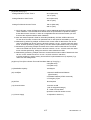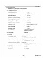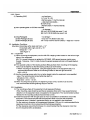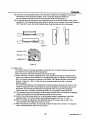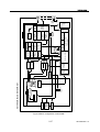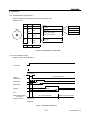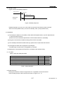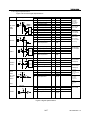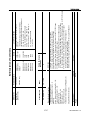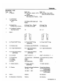
1
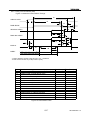
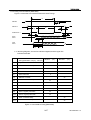
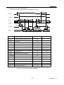
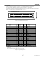
TOSHIBA
DISK PRODUCTS DIVISION
XM-7002B
CD-ROM DRIVE
PRODUCT SPECIFICATION
JUNE 1999
Rev. 1.0
Specifications are subject to change without notice
DOCUMENT NUMBER
12095
Notice
1.This product has no over-current protection circuit.
System should have appropriate over-current protection.
Toshiba Corporation makes no warranty of damages caused by no over-current protection.
2.This has a little possibility of errors.
To prevent damages and injury caused by the above, careful consideration for the safety and integrity
should be taken in the system design.
Do not use this product in a system that may cause hazard to human being or material loss caused by
the failure, loss of data and/or errors of this product.
3.Do not disassemble or modify this product.
Or, reliability, safety and performance can not be guaranteed.
4.Turn off the system power before mounting/removing this product.
Or, it may cause failure or damage.
5.Because the Interface connector of this product allows insertion of only one side direction, ascertain
direction carefully to insert the connector.
6.To built this product in an equipment, handle it only in electrostatically safe environment.
Do not touch connecting terminal directly or the product may be damaged by electrostatic energy.
7. This product can playback discs based on the format described in item 3.1.(1). Do not load a disc
which is not based on the item (discs of which outside is cut unevenly and is not a normal circle, etc.)
or a disc with its weight unbalanced excessively.
A very high speed rotation is carried out inside the product, so abnormal vibration and malfunction may
occur if disc described above is loaded.
8. When a disc cannot be ejected because of same troubles, etc., turn off the unit and eject the disc using
the emergency eject mechanism after passing more than 1 minute.
When the emergency eject is carried out while the power is on or immediately after the power off, the disc
may be eject in a rotating status. We do not assure if the disc is damaged by this.
9. Do not apply excessive force during the eject operation. The disc load inside the product may be ejected
in a rotating status.
Should the disc be damaged by the above action, we do not warranty against that.
10. In the instruction manual of your product, statement described in “Safety Instruction Manual “attached
to this product, the statement of item 2 and 8 above, and other required statements should be
mentioned for thorough understanding by the users.
XM-7002B Rev.1.0
Contents
1. Introduction ----------------------------------------------------------------------------------------------------------------------------- 1
2. Features --------------------------------------------------------------------------------------------------------------------------------- 2
3. Specifications ------------------------------------------------------------------------------------------------------------------------- 3
3.1. Performance --------------------------------------------------------------------------------------------------------------------- 3
3.2. Environmental Conditions ------------------------------------------------------------------------------------------------ 5
3.2.1. Temperature and Humidity ------------------------------------------------------------------------------------------- 5
3.2.2. Dusu and Dirt --------------------------------------------------------------------------------------------------------------- 5
3.2.3. Vibration --------------------------------------------------------------------------------------------------------------------- 5
3.2.4. Atmospheric Pressure and Altitude ------------------------------------------------------------------------------ 5
3.2.5. Shock ------------------------------------------------------------------------------------------------------------------------ 6
3.3. Installation Conditions ------------------------------------------------------------------------------------------------------- 6
3.3.1. Equipment ------------------------------------------------------------------------------------------------------------------ 6
3.3.2. Installation ------------------------------------------------------------------------------------------------------------------- 6
3.3.3. Back side -------------------------------------------------------------------------------------------------------------------- 7
3.3.4. Vibration detection ------------------------------------------------------------------------------------------------------ 8
3.4. Dimensions and Weight ----------------------------------------------------------------------------------------------------- 8
3.5. Reliability ------------------------------------------------------------------------------------------------------------------------ 10
3.5.1. Error Rate ----------------------------------------------------------------------------------------------------------------- 10
3.5.2. MTBF ----------------------------------------------------------------------------------------------------------------------- 10
3.5.3. MTTR ----------------------------------------------------------------------------------------------------------------------- 10
3.5.4. Drive Life ------------------------------------------------------------------------------------------------------------------ 10
3.5.5. Mechamical Life -------------------------------------------------------------------------------------------------------- 10
4. Configuration ------------------------------------------------------------------------------------------------------------------------- 10
4.1. Electrical Parts ----------------------------------------------------------------------------------------------------------------- 10
4.2. Optical Pickup ---------------------------------------------------------------------------------------------------------------- 10
4.3. Spindle Motor ---------------------------------------------------------------------------------------------------------------- 10
4.4. Feed Motor
------------------------------------------------------------------------------------------------------------------ 10
5. Functions ----------------------------------------------------------------------------------------------------------------------------5.1. CD-ROM Data Configurations -----------------------------------------------------------------------------------------5.2. Power ON/OFF Timing --------------------------------------------------------------------------------------------------5.3. Standby mode ---------------------------------------------------------------------------------------------------------------
12
12
12
13
6. Interface ------------------------------------------------------------------------------------------------------------------------------6.1. I/O cable ------------------------------------------------------------------------------------------------------------------------6.2.Signal summary --------------------------------------------------------------------------------------------------------------6.2.1.Signal Specifications ----------------------------------------------------------------------------------------------------6.2.2.Timing of Host Interface(PIO) ---------------------------------------------------------------------------------------6.2.3.Timing of Host Interface(DMA Multi) -----------------------------------------------------------------------------6.2.4.Timing of Host Interface(Ultra DMA) -----------------------------------------------------------------------------6.3. Connector ----------------------------------------------------------------------------------------------------------------------6.4.Suppor Commmand List -------------------------------------------------------------------------------------------------6.4.1.ATAPI Packet Command for CD-ROM Device ---------------------------------------------------------------6.4.2.ATA Commandfor ATAPI CD-ROM Device ---------------------------------------------------------------------
13
13
13
14
15
16
17
18
19
19
20
XM-7002B Rev.1.0
7. Power Requirements ------------------------------------------------------------------------------------------------------------7.1. Source Voltage -------------------------------------------------------------------------------------------------------------7.1.1. Spike ------------------------------------------------------------------------------------------------------------------------7.1.2. Ripple ---------------------------------------------------------------------------------------------------------------------7.2. Current Drain -------------------------------------------------------------------------------------------------------------------7.2.1. Sleep ------------------------------------------------------------------------------------------------------------------------7.2.2. Standby ---------------------------------------------------------------------------------------------------------------------7.2.3. Idle ----------------------------------------------------------------------------------------------------------------------------7.2.4. Continuous Read -------------------------------------------------------------------------------------------------------7.2.5. Average ---------------------------------------------------------------------------------------------------------------------7.2.6. Maximum -------------------------------------------------------------------------------------------------------------------7.2.7. Peak in executing Access -------------------------------------------------------------------------------------------7.2.8. Peak Current ----------------------------------------------------------------------------------------------------------------
21
21
21
21
21
21
21
21
21
21
21
21
21
8. Audio -----------------------------------------------------------------------------------------------------------------------------------8.1. Line Output --------------------------------------------------------------------------------------------------------------------8.1.1. Audio Cable --------------------------------------------------------------------------------------------------------------8.1.2. Connector ----------------------------------------------------------------------------------------------------------------8.2. Audio Modes --------------------------------------------------------------------------------------------------------------------
21
21
21
22
22
9. Device Configuration ------------------------------------------------------------------------------------------------------------ 22
9.1 Master mode setting ---------------------------------------------------------------------------------------------------------- 22
9.2 Slave mode setting ------------------------------------------------------------------------------------------------------------ 22
10. Busy Indicator ----------------------------------------------------------------------------------------------------------------------- 23
11. Maintenance ------------------------------------------------------------------------------------------------------------------------11.1. Disc ------------------------------------------------------------------------------------------------------------------------------11.2. Optical Pickup ----------------------------------------------------------------------------------------------------------------
24
24
24
12. Emergency Eject ------------------------------------------------------------------------------------------------------------------- 24
13. Safety Standards/Agency Approvals --------------------------------------------------------------------------------------- 24
14. Electrostatic Discharge ---------------------------------------------------------------------------------------------------------- 25
15. Accessories ------------------------------------------------------------------------------------------------------------------------- 25
16. Packaging ----------------------------------------------------------------------------------------------------------------------------
25
17. CE Declaration of conformity -------------------------------------------------------------------------------------------------
25
XM-7002B Rev.1.0
1. Introduction
This document describes Toshiba's XM-7002B CD-ROM Drive.
This drive reads digital data stored on CD-ROM and CD-Audio discs.
The CD-ROM disc is single sided and has a 12 cm or 8 cm diameter. It typically contains approximately
600 MBytes or 200 MBytes of information respectively. (1 MByte=220 Bytes)
This drive reads digital data stored on CD-ROM discs at maximum 24 times faster rotational speed.
This drive is a new generation drive with highest performance such as 95 ms (target) access Time.
This drive shows highest performance such as 60,000 hour MTBF.
This drive offer long life and high durability because the disc is read by a LASER, thereby eliminating physical
contact with the disc.
This drive support ATAPI (ATA Packet interface) Revision 2.6 spec. and SFF8090 Version 2
(Mt. Fuji Commands for CD and DVD-Devices) of CD/DVD Command.
1/27
XM-7002B Rev.1.0
2. Features
(1) Lightening by All Aluminum Cabinet Structure (180 g)
(2) 12.7 mm Height
(3) Support 12 cm/8 cm CD-ROM Disc Drive
(4) Rotational speed can be controlled by command
Max.24 (Ave.17X), Max.20X (Ave.14X), Max.16X (Ave.11X), Max.10X (Ave.7X)
(5) 95 ms (target) Random Access Time (Max.24X)
(6) Max.3,600 KBytes/s (Ave. 2,550 KBytes/s) Sustained Data Transfer Rate
(7) 5 V Single Voltage Source
(8) Support Multisession Disc ( Photo-CD, CD EXTRA), CD-R, CD-RW, CD-Text
(9) Support Multimedia PC-3 Spec.
(10) Support Windows PC98 Spec.
(11) Supprt ACPI Spec.
(12) Drawer Type Manual Load /Electrical Release
(13) Emergency Eject
(14) Built-in ATAPI Interface Controller
(15) Support < CD-DA Transfer Over ATAPI >Function
(16) Sub code P Thru W Transfer over ATAPI Bus
(17) Built-in MODE-1 ECC/EDC
(18) Embedded CD-ROM XA type ECC/EDC (in addition to standard type ECC/EDC)
(19) Efficient Data Transmission Throughput via large 128 KBytes Buffer Memory and
Buffer Algorithm
(20) 8X Sampling & Digital Filter for CD Audio
(21) Low Power Consumption. (Typ. 3.2 W) (20% Duty Random Access)
(22) 16-Mode Output for CD Audio
(23) Software Volume Control via ATAPI Mode Select Command
(24) MTBF 60,000 POH
(25) DataTransfer Rate
PIO Mode 4 (Data Transfer Rate16.7 MB/s)
DMA: DMA Multi Word Transfer Rate Mode 2
: Ultra DMA Transfer Rate Mode 2
(26) Support Vibration Detect Function
2/27
XM-7002B Rev.1.0
3. Specifications
3.1. Performance
(1) Applicable Disc Format*1
(2) Data Capacity(Yellow-Book)
User Data/Block
Red-Book, Yellow-Book, CD-ROM XA,
CD-IBridge ( Photo-CD, Video CD ), CD-I, CD-I
Ready,
CD-G and Multisession ( Photo-CD,CD EXTRA ),
CD-RW, CD-R, CD-TEXT
2,048 Byte/block(Mode 1)
2,336 Byte/block(Mode 2 Form 2)
(3) Rotational Speed* 2
Approx. 2,180 rpm (4.4-10X)
Approx. 5,200 rpm (10.3-24X)
(4) Transfer Rate
(1 KByte=210 Byte=1,024 Bytes, 1 Mbyte=220 Byte=1,048,576 Bytes)
Block Transfer Rate
Approx. 330-750 Block/s (4.4-10X)
Approx. 772-1,800 Block/s (10.3-24X)
Data Transfer Rate
(Yellow-Book Mode 1)
Approx. 660-1,500 KByte/s (4.4-10X)
Approx. 1,545-3,600 KByte/s (10.3-24X)
(Yellow-Book Mode 2)
Approx. 752-1,710 KByte/s (4.4-10X)
Approx. 1,716-4,104 KByte/s (10.3-24X)
Burst(ATAPI Interface)
16.7 MBytes/s (PIO Mode 4)
16.7 MByte/s (DMA multi word Mode2)
33.3 MByte/s (ULTRA DMA Mode2)
3/27
XM-7002B Rev.1.0
(5) Access Time (Typ.)
Average Random Access Time*3
95 ms (Max.24X)
110 ms (10X)
Average Random Seek Time*4
90 ms (Max.24X)
100 ms (10X)
Average Full Stroke Access Time*5
180 ms (Max.24X)
200 ms (10X)
*1: All CD formats, except CD Red book (audio), require additional application specific software
and/or hardware. The CD-ROM drive referenced in the specification is capable of reading
these data formats. However, in order to run applications that use these formats you must
first have the required software and/or hardware.
*2: Max 10X rotational speed is fixed for CD-audio (Red-Book), CD-RW, VIDEO-CD format.
For the other Formats, it is Max.24X speed but 20X or 16X speed is selectable by command.
*3: Measured by performing multiple accesses which means reads of data blocks over whole
area of the media from 00 min. 02 sec. 00 block to 60 min. 01 sec. 74 block more than 3000
times. Includes positioning, setting, latency time and ECC implementation time (if required).
*4: Measured by performing multiple accesses which means seeks of data blocks over whole
area of the media from 00 min. 02 sec. 00 block to 60 min. 01 sec. 74 block more than 3000
times. Includes positioning, setting time which is same definition as HDD.
*5: Measured by performing multiple maximum accesses which means reads of data blocks from
00 min. 02 sec. 00 block to 60 min. 01 sec. 74 block more than 100 times.
Includes positioning, setting, latency time and ECC implementation time (if required). Typ.
value is for the average drive.
(6) Spin up Time (Focus Search Time and Disc Motor Start up Time)(Typ.)
2.8 s (Max.24X)
2.2 s (Max.10X)
(7) Data Buffer Capacity
128 KBytes
(8) Load/Eject
1. Manual Load/Electrical Release
(Eject Button)
2. Software Release (ATAPI command)
3. Emergency Eject
(9) Air Flow
Not Required
(10) Acoustic Noise
Less than 40 dB
(with A weighted/Average)
at 1 meter of Front Bezel
Operation mode:Full stroke Access
(11) Power Supply
+5 V(details in Section 7)
4/27
XM-7002B Rev.1.0
3.3.4. Vibration detection
(1) This drive detects vibration which occurs when unbalanced disc is played, and rotation speed
of two steps (16X, 10X) is selected according to the vibration level and the rotation speed
is dropped automatically.
It is necessary to mount the drive stably in PC to detect the vibration correctly.
(2) This drive was tuned up to detect the vibration on the assumption that the drive was mounted
in Toshiba DynaBook Satellite Pro 440 series.
Mounting condition in Toshiba DynaBook Satellite Pro 440 series is shown in Figure 3.
There will be possibility that the drive does not detect the vibration. It depends on mounting
condition.
M2 Screws
CD-ROM Drive
M2 Screws
Gutter
(1)
Toshiba DynaBook
Satellite Pro 440 series
PC Adapter
M2 Screws
(2)
PC Mounting
Adapter Mounting
Figure 3
3.4. Dimensions and Weight
(1) External Dimensions (W x H x D)
(2) Mass (Weight)
---See Figure 4 for details--128.0 mm x 12.7 mm x 129.0 mm
0.18 kg (Net)
233 kg (36 Bulk Packaged on one pallet)
135 kg (24 Bulk Packaged on one pallet)
8/27
XM-7002B Rev.1.0
(Unit:mm)
Figure 4 External Dimensions
9/27
XM-7002B Rev.1.0
3.5. Reliability
3.5.1. Error Rate
(1) Hard Read Error Rate (Byte Error Rate)
Yellow-Book Mode 1/Mode 2 Form1
Yellow-Book Mode 2/Mode 2 Form2
----- Allowing 10 Retries ----10 -15 Max
10 -12 Max
(2) Seek Error Rate ---Allowing Retries--10 -6 Max
3.5.2. MTBF
Assumptions: Power On Hours
On/Off Cycles
Number of Access
Operating Duty Cycle
60,000 POH
5,436 h/year
312 cycles/year
600,000 accesses/year
20 % of Power On Time
(Reading/Seeking)
3.5.3. MTTR
0.5 h
3.5.4. Drive Life
15,000 h or 5 years(earlier one)
3.5.5. Mechanical Life
(1) Drawer Load/Eject
10,000 times or more
(2) Interface Connector Attach/Detach
500 times or more
4. Configuration
See Figure 5 for details of the configurations.
4.1. Electrical Circuits
(1) Drawer Eject Switch
(2) Optical Pickup Servo Control Circuit
(3) Feed Motor Drive Circuit
(4) Laser Diode Control Circuit
(5) EFM Demodulator and CD-ROM Error Correction Circuit
(6) IDE/ATAPI Interface Control Circuit
(7) System Control Circuit
(8) Analog Audio output
4.2. Optical Pickup
Semiconductor Laser and 3-beam System
4.3. Spindle Motor
Brush- less DC Motor
4.4. Feed Motor
DC Motor with Non-contact Type Velocity
sensor
10/27
XM-7002B Rev.1.0
Figure 5 Basic configuration of XM-7002B
11/27
XM-7002B Rev.1.0
BUSY
LED
DRAWER
RELEASE
DETECTOR
EJECT SW
MO DRIVER
POSITION
DETECTOR
FEED MOTOR
SOLENOID
EJECT
DISC
MOTOR
PUH
XM-7002B BLOCK DIAGRAM
Eject
FN
CONV.
ACCESS
CONTROL
Feed-Mo
FOCUS
TRACKING
SERVO
AMP
RF AMP
AUDIO FILTER
MASTER
CLOCK GEN.
ERROR
CORRECTION
RAM
AUDIO
DAC
EFFECT
TIMER
INT.CONTROL
50 MHz
ERROR
CORRECTION
HEADER
DETECT
DE-SCRAMBLE
CD-ROM
SYNC DETECT
D-RAM
128 kB
MICRO PROCESSOR
Z80 Compatible
TIMING
CONTROL
33.86 MHz
PERIPHERAL INTERFACE
SERVO
CONTROL
VCO
17/34 MHz
VCO
CONTROL
EFM DE-MOD
MUTING
RAM
2 kB
ROM
512 KB
GND
+5V
FLASH
IDE/ATAPI
INTERFACE
CONTROL
DATA
CONTROL
5. Functions
5.1. CD-ROM Data Configurations
Figure 6 shows how the data is structured in program units.
1block=1/75 s
TNO Time
0
TOC
Min
Sec
Block
1-Disc
1
Min
Sec
Block
AA
Block 1
~
Minutes
Second(0~59)
4 bytes
User Data
2048 bytes in Mode-1
2336 bytes in Mode-2
Block 2
~
Blocks(0~74)
Mode
~
approx.
300kBlocks
2
~
SYNC
12 bytes
Header
Lead-in
~
ECC(Mode-1)
288 bytes
~
~
~
Lead out
Figure 6 CD-ROM Data Configuration
5.2. Power ON/OFF Timing
Figure 7 shows the initialization.
Power ON
Max 500 ms
System
Initialization
"Command" Receivable
Max 2 s
Focus Serch
Max 3.5 s
Spindle ON
Typ.13 s, Max 16 s
(Single Session Disc)
Learning
Idle
"TEST UNIT READY"
Command
Correspondence
Any Command Sendable
Can't send
"Check Condition"Status
"Read-Command"Acceptable
"Good"Status
COMMAND
Figure 7 Initialization Sequence
12/27
XM-7002B Rev.1.0
5.3. Standby mode
Figure 8 shows the standby sequence.
During acces s
ldle (Max.24X)
ldle (4.4 - 10X)
Read or Seek
command
8s
24 s
Figure 8 Standby Sequence
Rotational speed move onto 4.4 to 10X mode in 8 seconds of the Read or Seek command.
After 24 seconds (default value), it move onto standby mode. (a stop spindle motor)
6. Interface
(1) The interface is based on ATA-SPEC, ATAPI-SPEC SFF-8020i Revision 2.6, SFF-8028 Revision
1.0 and SFF-8090 version 2.
(Small Form Factor Committee Specification of ATA-Packet Interface for CD-ROMs)
(2) 48 types of commands are usable including ATA & ATAPI Commands.
(3) The 128 KByte data buffer handles both high speed and low speed data transmission.
(4) The largest one block size on playback is 2,448 Bytes.
The data length for each block is changeable by command.
(5) Please refer to the standard of ATA/ATAPI-4 for details of the interface timing.
6.1. I/O cable
Table 1 shows the cable parameters.
Min
Max
0.46 m
Cable length
Driver IoL sink current for 5V operation
Driver IoH source current
12 mA
-400 µA
Cable capacitive loading
200 pF
Power Supply cablesPIN No.38 - 42(+B),43 - 45(GND)
1.5 A
Table 1 Cable parameters
6.2.Signal summary
The physical interface consists of single ended TTL compatible receivers and drivers
communicating through a 50P-conductor as shown in Figure 9,10 - 13.
13/27
XM-7002B Rev.1.0
6.2.1.Signal Specifications
Figure 9 shows the Signal Specifications
Sig. Name
Rx
DD0 -DD15
/DASP
/PDIAG
Ri
Receivers/Drivers Caracteristics withoutExternal pullup Resistor
Min
Max
Condition
IOH=1
mA
VOH Voltage Output High
Vdd-0.4 V
Voltage
Output
Low
0.4
V
IOL=12
mA
VOL
Input
HIGH
Voltage
VIH
2.0 V
TTL
VIL Input LOW Voltage
0.8 V TTL
P
ILI
Type
Rs
N
timing
control
Ri
Rx
/IOCS16
Rs
N
Input leakage Current
IOL
ILO
IORDY
P
Rs
N
timing
control
12 mA
-30 µA -150 µA Pullup Resistor(Ri)
8 pF
8 pF
0.4 V IOL=24 mA
IOL
Driver sink current
24 mA
ILO
Output Leakage Current
-30 µA -150 µA Pullup Resistor(Ri)
CO
Output Capacitance
VOL Voltage Output Low
IOL Driver sink current
ILO Output Leakage Current
CO
DMARQ
INTRQ
N
/DIOW
Rx
/DIOR
DA0 - DA2
Ri
Rs
/CS1FX
timing
control
Rx=10 kOHM
Ri=20 kOHM
Rs=0 OHM
/PDIAG
/DASP
Rx=10 kOHM
Ri=100 kOHM
Rs=0 OHM
Open Drain
Rs=0 OHM
Rx=10 kOHM
Ri=infinity
8 pF
IOH=400 µA
2.4 V
0.4 V
IOL=24 mA
Rs=22 OHM
Rx=10 kOHM
IOH=400 µA
IOL=12 mA
DMARQ
Rs=22 OHM
3 state(Hiz)
24 mA
-10 µA 10 µA
Output Capacitance
VOH Voltage Output High
VOL Voltage Output Low
P
Rs
-5 µA -150 µA Pullup Resistor(Ri)
Driver sink current
Output Leakage Current
Input Capacitance
CI
CO
Output Capacitance
VOL Voltage Output Low
VOH Voltage Output High
Rx
NOTE
Bidirectional
Rx=infinity
Ri=infinity
Rs=33 OHM
DD0-DD15
8 pF
Vdd-0.4 V
0.4 V
IOL
Driver sink current
12 mA
ILO
Output Leakage Current
-10 µA
CO
Output Capacitance
VIH
VIL
Input HIGH Voltage
ILI
Input leakage Current
CI
Input Capacitance
10 µA
INTRQ
Rs=22 OHM
3 state(Hiz)
8 pF
TTL
2.0 V
Input LOW Voltage
0.8 V
-5 µA
TTL
-150 µA Pullup Resistor(Ri)
Ri=100 kOHM,
Rx=infinity,
Rs=82 OHM
/DMACK,/DIOW,/DIOR
DA0 - DA2
Ri=100 kOHM,
Rx=10 kOHM
8 pF
Rs=82 OHM,
/CS1FX,/CS3FK
/CS3FX
Ri=infinity,
Rx=10 kOHM
Rs=470 OHM,
CSEL
CSEL
/DMACK
Rx
/RESET
VIH
VIL
ILI
CI
Input HIGH Voltage
Input LOW Voltage
Input leakage Current
TTL
TTL
-5 µA -150 µA Pullup Resistor(Ri)
2.0 V
Input Capacitance
Rs
0.8 V
Rx=100 kOHM
Rs=1 kOHM
8 pF
Figure 9 Signal Specifications
14/27
XM-7002B Rev.1.0
6.2.2. Timing of Host Interface (PIO)
Figure 10 shows the Host Interface Timings.
t0
Address valid*1
t2
t1
t9
DIOR-/DIOW-
t2i
Write data valid*2
t8
t3
Read data valid*2
t4
t5
t7
t6Z
t6
IOCS16tA
tB
tRD
IORDY
*1:Device Address consists of signals CS0-, CS1-, and DA2-0
*2:Data consists of DD0-15 (16-bit) or DD0-7 (8-bit)
t0
t1
t2
t2i
t3
t4
t5
t6
t6Z
t7
t8
t9
tRD
tA
tB
PIO Mode 4 timing parameters min(ns) max(ns)
Cycle time
Address valid to DIOR-/DIOW-setup
DIOR-/DIOW- pulse wide
DIOR-/DIOW- recovery time
DIOW- data setup
DIOW- data hold
DIOR- data setup
DIOR- data hold
DIOR- data tristate
Addr valid to IOCS16- assertion
Addr valid to IOCS16- negation
DIOR-/DIOW- to address valid hold
Read Data Valid to IORDY active
IORDY setup time
IORDY pulse wide
Min Time (ns) Max Time (ns)
120
25
70
25
20
10
20
5
30
30
30
10
0
35
1250
Figure 10 Host Interface Timin
15/27
XM-7002B Rev.1.0
6.2.3.Timing of Host Interface (DMA Multi)
Figure 11 shows the Host Interface DMA multi word Timings
t0
DMARQ
tL
DMACK-*1
tK
tD
tJ
tI
DIOR/DIOW-*1
tZ
tE
Read
DD0-1
tF
Write
DD0-1
tG
tH
*1: In all timing diagrams, the low line indicator negated, and the upper line
indicators asserted.
Multi word DMA Mode 2
timing parameters min (ns)
max (ns)
Min time
(ns)
Max time
t0
Cycle time
tC
DMACK to DMREQ delay
tD
DIOR-/DIOW-
tE
DIOR- data access
tF
DIOR- data hold
tZ
DMACK- to tristate
tG
DIOR/DIOW- data setup
20
tH
DIOW- data hold
10
tI
DMACK to DIOR-/DIOW- setup
0
tJ
DIOR-/DIOW- to DMACK hold
5
tKr
DIOR- negated pulse width
25
tKw
DIOW- negated pulse width
25
tLr
DIOR- to DMREQ delay
35
tLw
DIOR- to DMREQ delay
35
(ns)
120
---
16-bit
70
50
5
25
Figure 11 Host Interface Timing (DMA Multi)
16/27
XM-7002B Rev.1.0
6.2.4.Timing of Host Interface (Ultra DMA )
Figure 12 shows the Host Interface Ultra DMA word Timings
tMLI
DMARQ
tUI
DMACK-
tCYC
STOP
tRP
t2CYC
tFS
tACK
tCYC
tENV
tACK
tLI
DMARDY
t2AD
tRFS
t2IORDY
STROBE
tDVS tDVH tDVS
tDVH
tDVS tDVH
tDVS tDVH
DD
(15:0)
CRC
Ultra DMA Mode 2
timing parameters min (ns)
max (ns)
Min time
(ns)
t2CYC
Typical Sustained Average Cycle time
tCYC
Cycle time
55
tDVS
Data Setup time
34
tDVH
Data Hold time
6
tUI
Unlimited Interlock time
0
tACK
Setup and Hold Time for DMACK-
20
tENV
Envelope time
20
t2AD
Minimum Delay time for Driver
t2IORODY
Minimum time for DMACK-
tFS
First STROBE time
tRFS
Ready-to-Final STROBE time
tRP
Ready-to-Pause time
100
tLI
Limited Iuterlock time
0
tMLI
Interlock with minimum
Max time
(ns)
120
70
0
20
0
170
50
150
20
Figure 12 Host Interface Timing (Ultra DMA)
17/27
XM-7002B Rev.1.0
6.3. Connector
Figure 13 shows the connector and Figure 14 shows the interface pin assignments
Use Japan Aviation Electronics Industry Limited KX15-50KLD L or equivalent.
Conformable connector is Japan Aviation Electronics Industry Limited KX14-50K*D or equivalent.
(Note: * is No.2.85,5, 8, 11. The recommendation is No.5)
TOP
CD-ROM DRIVE REAR VIEW
4
6
2
8
1
7
5
12
10
3
9
16
14
11
15
13
22
20
24
18
21
26
17
23
28
19
27
32
30
25
31
29
36
34
40
38
33
37
35
39
46
44
48
42
45
50
41
47
43
49
BOTTOM
Figure 13 Connector pin assignments
Signal
name
Audio L-CH
Audio Ground
/RESET
DD7
DD6
DD5
DD4
DD3
DD2
DD1
DD0
Digital Ground
/DIOW: STOP
IORDY: /DDMARDY: DSTROBE
INTRQ
DA1
DA0
/CS1FX
/DASP
+5 V(MOTOR)
+5 V(LOGIC)
Ground
Ground
Device Config.(CSEL)
N.C (OPEN)
I/O
O
I
I/O
I/O
I/O
I/O
I/O
I/O
I/O
I/O
I
O
O
I
I
I
I/O
I
I
I
Connector
contact
2
1
3
4
5
6
7
8
9
10
12
11
13
14
16
15
17
18
19
20
21
22
23
24
25
26
27
28
29
30
31
32
33
34
35
36
37
38
40
39
42
41
43
44
45
46
48
47
49
50
I/O
O
I/O
I/O
I/O
I/O
I/O
I/O
I/O
I/O
O
I
I
O
I/O
I
I
I
I
I
I
Signal
name
Audio R-CH
Digital Ground
DD8
DD9
DD10
DD11
DD12
DD13
DD14
DD15
DMARQ
/DIOR: /HDMARDY: HSTROBE
Digital Ground
/DMACK
/IOCS16
/PDIAG
DA2
/CS3FX
+5 V(MOTOR)
+5 V(MOTOR)
+5 V(LOGIC)
Ground
Ground
Ground
Vender unique *
A slash character(/) at the beginning of a signal name indicates it is asserted at the low level
(active low).
* Do not connect anything with vender unique (50P).
Figure 14 Signal assignments
18/27
XM-7002B Rev.1.0
6.4.Support Command List
6.4.1. ATAPI Packet Command for CD-ROM Devices
Command
AUDIO SCAN
GET EVENT STATUS NOTIFICATION
GET CONFIGRATION COMMAND
GET PERFORMANCE COMMAND
INQUIRY
MECHANISM STATUS
MODE SELECT(10)
MODE SENSE(10)
PAUSE/RESUME
PLAY AUDIO(10)
PLAY AUDIO(12)
PLAY AUDIO MSF
PLAY TRACK RELATIVE(10)
PLAY TRACK RELATIVE(12)
PREVENT/ALLOW MEDIUM REMOVAL
READ(10)
READ(12)
READ C/DVD CAPACITY
READ CD
READ CD MSF
READ DISC INFORMATION COMMAND
READ FORMATTED CAPACITIES COMMAND
READ HEADER
READ SUB-CHANNEL
READ TOC
READ TRACK/RZONE INFORMATION COMMAND
REQUEST SENSE
REZERO UNIT
SEEK
SET CD-ROM SPEED
SET READ AHEAD COMMAND
SET STREAMING COMMAND
SEND EVENT COMMAND
STOP PLAY/SCAN
START/STOP UNIT
TEST UNIT READY
19/27
OP Code
BAh
4Ah
46h
ACh
12h
BDh
55h
5Ah
4Bh
45h
A5h
47h
49h
A9h
1Eh
28h
A8h
25h
BEh
B9h
51h
23h
44h
42h
43h
52h
03h
01h
2BH
BBh
A7h
B6h
A2h
4Eh
1Bh
00h
XM-7002B
YES
YES
YES
YES
YES
YES
YES
YES
YES
YES
YES
YES
YES
YES
YES
YES
YES
YES
YES
YES
YES
YES
YES
YES
YES
YES
YES
YES
YES
YES
YES
YES
YES
YES
YES
YES
XM-7002B Rev.1.0
6.4.2. ATA Command for ATAPI CD-ROM Devices
Command
ATAPI SOFT RESET
CHECK POWER MODE
EXECUTE DRIVE DIAGNOSTICS
IDLE IMMEDIATE
IDLE
NOP
ATAPI PACKET COMMAND
ATAPI IDENTIFY DEVICE
SET FEATURES
SLEEP
STANDBY IMMEDIATE
STANDBY
OP Code
08h
E5h
90h
E1h
E3h
00h
A0h
A1h
EFh
E6h
E0h
E2h
20/27
XM-7002B
YES
YES
YES
YES
YES
YES
YES
YES
YES
YES
YES
YES
XM-7002B Rev.1.0
7. Power Requirements
7.1. Source Voltage
7.1.1 Spike
7.1.2 Ripple
+5 V +/-5 % (Operating)
100 mV (p-p) Max
100 mV (p-p) Max
7.2. Current Drain (Typ. Value)
7.2.1. Sleep(Minimum Current Mode)
7.2.2. Standby(Laser off,motor off)
7.2.3. Idle(Laser on,motor on)
Start Position
7.2.4. Continuous Read(Audio/Data)
Start Position
7.2.5. Average(20% Duty Random Access)
7.2.6. Maximum(100% Duty Random Access)
7.2.7. Peak in executing Access
(With out Spike Current*)
7.2.8. Peak Current
(With out Spike Current)*
*Spike:Less than 1ms width current
0.025 A
0.03 A
0.32 A
0.62 A (Max.24X) / 0.35 A (Max.10X)
0.64 A (Max.24X) / 0.34 A (Max.10X)
0.76 A ( Max.24X) / 0.44 A (Max.10X)
1.4 A
1.5 A
8. Audio
8.1. Line Output ----- in case of the attenuator is set at 0 dB by the command ----(1) Output Level
0.775 V (rms Typ)+/- 3 dB
(2) Type
Unbalanced
(3) Output Impedance
2.2 kOHM
(4) Load Impedance
47 kOHM
(5) Frequency Response
20 Hz to 20 kHz +/- 3.0 dB.(at 47 kOHM Load)
(6) Distortion
0.03 % Max. (at 1 kHz weighted 20 kHz LPF)
(7) Signal to Noise Ratio
78 dB Typ (IEC 179 A-weighted)
8.1.1. Audio Cable
Unbalanced and shielded
(1) Capacitance
Less than 1000 pF
(2) Length
Max. 3 m
21/27
XM-7002B Rev.1.0
8.1.2. Connector
Figure 13, 14 shows the connector and Audio signal pin assignment.
8.2. Audio Modes
(1) 16 Modes including 'Stereo', 'Lch Mono', 'Rch Mono' and 'Mute' are selectable by command.
Default mode is 'Stereo'.
The audio output is automatically muted in the state other than the time of audio track playback.
(2) 16 Steps of attenuation level for the Audio Output is selectable by command.
Default level is 0 dB.
9. Device Configuration
9.1 Master mode setting
Open the PIN 47 of I/O conectors.
9.2 Slave mode setting
Short-circuit the PIN 47 and PIN 48 of I/O connectors.
*Master mode can be oppositely to Slave mode according to the specification. (CSEL mode)
22/27
XM-7002B Rev.1.0
10. Busy Indicator
The LED at Front Bezel (Busy Indicator) indicates the drive status.
Color: UMBER
(1) After Drawer is closed, Busy Indicator start blinking at 0.8 s intervals, and then ----(1-1) Turns off when the drive in the 'Idle' status.
0.8 s
Light Off
Figure 15 Idle
(1-2) Continuously off when no disc is mounted.
0.8 s
Light Off
Figure 16 No disc
(1-3) Continuously on when media has problem
0.8 s
Light On
Figure 17 Media Problem
(2) When playing an audio track, Busy Indicator is blinking at 1.6 s intervals.
1.6 s
Figurer 18 CD-Audio playback
(3) When performing 'Data Access' and during 'Data Transfer' Busy Indicator keeps turn On.
Light On
Figurer 19 Data Access and Data Transfer
(4) When pushing Eject button, Busy indicator is blinking at 0.4 s intervals.
0.4 s
Light Off
at the Eject
Figurer 20 Eject
23/27
XM-7002B Rev.1.0
11.Maintenance
11.1. Disc
Try to avoid touching the read area (underside) of the disc as dirt and smears will degrade
the disc accessing speed.
If the disc is dirty, wipe it with a soft cloth.
11.2. Optical Pickup
A dirty Optical Pickup will also degrade the access time.
When the Pickup is dirty, gently wipe the objective lens of the Pickup.
12.Emergency Eject
Execute following procedure only in the case of emergency (drawer will not eject although pressing
Eject button).
(1) Turn the CD-ROM drive supplying power off, and then keep the this condition for 1 minute.
(2) Insert solid bar (like paper clip) into Emergency eject hole and push as shown in Figure 21.
Then Tray will be ejected.
15 mm
diameter 1.0 mm
Figurer 21 Insert the bar
13.Safety standards/Agency Approvals
(1) Safety
EN60950
UL 1950
CAN/CSA-22.2 No.950
(2) Laser
FDA CFR21, EN60825
(3) EMI
FCC 15J - B
(4) CE
EN50081-1
:1992 [Residential, commercial & light industry]
EN55022+A2 :1994+1997 [Class B]
EN55024
:1997 [Information tecnology equipment-Immunity
characteristics-Limits and methods of
measurement]
IEC61000-4-2+A1:1995+1998 [CD:4 kV, ID: 4 kV, AD:8 kV]
IEC61000-4-3 :1996 [3 V/m, 80-1000 MHz, 1 kHz 80 % AM ]
IEC61000-4-4 : 1995 [AC-line: 1 kV, f: 5 kHz, Polarity:+/- ]
IEC61000-4-5 : 1995 [AC-line: 1 kV/2 kV, Polarity:+/- ]
IEC61000-4-6 : 1996 [3 V, 0.15-80 MHz, 1 kHz 80 % AM]
IEC61000-4-8 : 1993 [1 A/m, 50 Hz]
(5) EMI
KOREAN EMI Regulation (RRL)
24/27
XM-7002B Rev.1.0
14. Electrostatic Discharge
(1) Operating (Air discharge)
15 kV or less
(2) Damage including (Air discharge)
20 kV or more
15. Accessories
Non
16. Packaging
a. 25 units in a Bulk Pack
36 Bulk Packs on one Pallet
*Transportaion must be executed with each palette.
b. 20 units in a Bulk Pack
24 Bulk Packs on one Pallet
Packing Specifications
:for 25 Packaged Model: IB-CD2-A90012
:for 20 Packaged Model: IB-CD2-A90013
17. CE Declaration of conformity
Please refer to attached Annex 1.
25/27
XM-7002B Rev.1.0
TOSHIBA
TOSHIBA EUROPE GMBH
EU-Declaration of Conformity
Product:
CD-ROM Drive
Manufacturer(s):
Toshiba Corporation
1-1, Shibaura 1-chome, Minato-ku, Tokyo 105-8001 Japan
See page 2 for other locations
Model:
XM-7002B
Options:
None
Toshiba declares that the above mentioned product(s) with or without
the listed options comply to the EU-Directives and standards as listed on page 2.
Last two digits of the year in which the CE mark affixed : 98
Responsible for CE-marking:
Toshiba Europe GmbH
Signed by:
Mr. H.Nonaka, President of Toshiba Europe GmbH
Place:
D-41460 Neuss
Date:
May 07, 1999
Signature:
----------------------------------------------------------
This declaration certifies compliance with the listed directives, but does not constitute an
assurance of characteristics.
The safety information in the supplied product documentation must be observed.
............................................................................................................................................................
Document No.:
YEA-T023
Page:
1 of 2
............................................................................................................................................................
[History if issue]
Issued
: May 06, 1999
...................................................
Revision A
:
Ref.:
...................................................
.........................
Revision B
:
Ref.:
...................................................
.........................
Revision C
:
Ref.:
...................................................
.........................
Revision D
:
Ref.:
...................................................
.........................
TOSHIBA EUPOPE GMBH
HAMMFELODAMMB.D-41460NEUSS
GESCHAFTSUHRER
POSTFCH 101482. D-41414 NEUSS
HISATSUGU NONAKA
TELEFON: (02131) 158-01
HRB 3479 AMTSGERICHT NESS
TELFAX : (02131) 158-341
Annex 1
26/27
XM-7002B Rev.1.0
27/27
XM-7002B Rev.1.0
XM-7002B
CD-ROM Drive
YEA-T023
2 of 2
Document No.:
Page:
Integrated Microelectronic Inc.
Toshiba Multi Media Devices Co, L
Toshiba Misawa Media Devices Co, Lt
EMS Corp.
Hokuto Communication Industrial Co., Ltd.
Yuzawa Denshi Kogyo Co., Ltd.
EMS Kizukuri Corp.
Emusu Itayanagi Co., Ltd.
EMS Fukaura Co., Ltd
Tsugaru Technica Co., Ltd.
Toshiba Information Equipment (Philippines) Inc
Manufactuer(s) Location
Model
1995+1998
1996
1995
1995
1996
1993
IEN61000-4-2+A1
IEN61000-4-3
IEN61000-4-4
IEN61000-4-5
IEN61000-4-6
IEN61000-4-8
EMC-immunity
Product/Options
1997
EN5524
EMC-emission:
899/336/EEC
(EMC Directive)
Information tecnology equipment-Immunity
characteristics-Limits and methods measurement
CD: 4 kV, ID: 4 kV, AD: 8 kV
3 V/m, 80-1000 MHz, 1 kHz 80 % AM
AC-line: 1 kV, f: 5 kHz, Polarity: +/AC-line: 1 kV/2 kV, f: 5 kHz, Polarity: +/3 V, 0.15-80 MHz, 80 % AM
1 A/m, 50 Hz
Residential, commercial & light industry
Class B
Level/Test condition
Revision:
19 Minase, Fukihata Goshogawara-shi, Aomori 037-0003 Japan
3-31-2779, Minami-cho, Misawa-shi, Aomori-ken 033-0036 Japan
4-5 Shoubu, Ubayachi Goshogawara-shi, Aomori 037-0015 Japan
207 Aza Koamon, Rokugo, Rokugo-machi, Senboku-gun, Akita 019-1404 Japan
257 Nakano Yuzawa-shi, Akita 012-0041 Japan
1-2 Aza-Miyazaki, Kizukuri-machi, Nishi-Tugaru-gun Aomori 038-3157 Japan
13-10, Matsumoto, Tsuji, Itayanagi, Kita-Tyugaru-gun, Aomori, 038-3645 Japan
24-1 Aza Azumazawa, Ohaza Fukaura, Fukaura-machi, Nishi-Tsugaru-gun, Aomori, 037-0401 Japan
81-87 Iwai, Aiuchi, Shiura-machi, Kitatsugaru-gun, Aomori, 037-0401 Japan
103 East Main Avenue Extension, Special Export Processing Zone,
Laguna Technopark, Binan, Laguna Philippines
North Science Avenue Laguna Techno Park Inc. Binan, Laguna Philippines
Address
X
Related EU-Directive
89/336/EEC
1992
1994+1997
EN50081-1
EN55022+A2
Related Standard
ED-Directive
Issude
EU-Declaration of Conformity