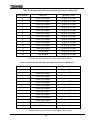
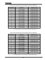
1
Uninterruptible Power System (UPS)
G8000 Series
Installation Manual
•
REQUIREMENT
S
Read this operation manual
carefully before
installing the UPS.
•
Retain this manual with the UPS for easy
reference when required.
•
This manual was written for the consulting
engineer, architect, and electrical contractor.
Document Number: 57490-000
February 2005
© TOSHIBA Corporation 2005
All Rights Reserved.
Notice
Please inform Toshiba Corporation or authorized representatives in case of inconsistencies,
omissions, or questions.
The instructions contained in this manual are not intended to cover all of the details or variations in
equipment, or to provide for every possible contingency concerning installation, operation, or
maintenance. Should further information be required or if problems arise which are not covered
sufficiently contact your Toshiba sales office.
The contents of this instruction manual shall not become a part of or modify any prior or existing
agreement, commitment, or relationship. The sales contract contains the entire obligation of Toshiba
International Corporation's UPS Division. The warranty contained in the contract between the parties
is the sole warranty of Toshiba International Corporation's UPS Division and any statements
contained herein do not create new warranties or modify the existing warranty.
Any electrical or mechanical modifications to this equipment without prior written consent of
Toshiba International Corporation will void all warranties and may void the UL/CUL listing.
Unauthorized modifications can also result in personal injury, death, or destruction of the
equipment.
1. Introduction
This manual is intended to help implement safe and correct transportation, installation and wiring of the
G8000 Series Uninterruptible Power System (hereafter referred to "UPS").
Before transportation, installation and wiring of the UPS, please read through all of the chapters. Above
all, read the “General Safety Instructions,” “Important Safety Instructions,” “Safety Precautions” and
“Installation Precautions” chapters, as these must be carefully read. Please make sure that you have a
thorough understanding of the information in these 4 chapters.
Personnel that will install the UPS should carefully read this manual before installation.
Keep this manual close to the UPS so you can refer whenever necessary.
Also, please read through the "Operation Manual." The Operation Manual describes the important
instructions to be used during UPS operation. The manuals should remain together.
1
UNINTERRUPTIBLE POWER SUPPLY
Complete the information below for the UPS system received.
Unless otherwise specified, the warranty period for the UPS or UPS part is 36 months from the
shipment date (see TIC bill of lading).
Unless otherwise specified, the warranty period for a UPS battery is 24 months from the shipment
date (see TIC bill of lading).
Please complete the following information and retain for your records.
Job Number:
Model Number:
Serial Number:
Application:
Shipment Date:
Installation Date:
Inspected By:
2
Manual’s Purpose and Scope
This manual provides information on how to safely install, operate, and maintain your TIC power
electronics product. This manual includes a section of general safety instructions that describes the
warning labels and symbols that are used throughout the manual. Read the manual completely
before installing, operating, or performing maintenance on this equipment.
This manual and the accompanying drawings should be considered a permanent part of the
equipment and should be readily available for reference and review. Dimensions shown in the
manual are in metric and/or the English equivalent.
Toshiba International Corporation reserves the right, without prior notice, to update information,
make product changes, or to discontinue any product or service identified in this publication.
TOSHIBA is a registered trademark of the Toshiba Corporation. All other product or trade references
appearing in this manual are registered trademarks of their respective owners.
Toshiba International Corporation (TIC) shall not be liable for direct, indirect, special, or
consequential damages resulting from the use of the information contained within this
manual.
This manual is copyrighted. No part of this manual may be photocopied or reproduced in any form
without the prior written consent of Toshiba International Corporation.
© Copyright 2005 Toshiba International Corporation.
All rights reserved.
Printed in the U.S.A.
Contacting Toshiba’s
Support Center
Customer
Toshiba’s Customer Support Center can be contacted to obtain help in resolving any
Uninterruptible Power Supply system problems that you may experience or to provide application
information.
The center is open from 8 a.m. to 5 p.m. (CST), Monday through Friday. The Support Center’s toll
free number is US (800) 231-1412/Fax (713) 466-8773.
You may also contact Toshiba by writing to:
Toshiba International Corporation
13131 West Little York Road
Houston, Texas 77041-9990
Attn: UPS Product Manager.
For further information on Toshiba’s products and services, please visit our website at
www.tic.toshiba.com.
3
2. General Safety Instructions
DO NOT attempt to install, operate, maintain or dispose of this equipment until you have read and
understood all of the product safety information and directions that are contained in this manual.
Safety Alert Symbol
The Safety Alert Symbol indicates that a potential personal injury hazard exists. The symbol is
comprised of an equilateral triangle enclosing an exclamation mark.
Signal Words
Listed below are the signal words that are used throughout this manual followed by their descriptions
and associated symbols. When the words DANGER, WARNING and CAUTION are used in this
manual they will be followed by important safety information that must be carefully adhered to.
The word DANGER preceded by the safety alert symbol indicates that an imminently hazardous
situation exists that, if not avoided, will result in death or serious injury to personnel.
DANGER
The word WARNING in capital letters preceded by the safety alert symbol indicates that a potentially
hazardous situation exists that, if not avoided, could result in death or serious injury to personnel.
WARNING
The word CAUTION in capital letters preceded by the safety alert symbol indicates that a potentially
hazardous situation exists which, if not avoided, may result in minor or moderate injury.
CAUTION/ATTENTION
The word CAUTION or ATTENTION in capital letters without the safety alert symbol indicates a
potentially hazardous situation exists which, if not avoided, may result in equipment and property
damage.
CAUTION
4
3. IMPORTANT SAFETY INSTRUCTIONS
This instruction contains important
instructions for the G8000 Series
that should be followed during the installation, operation, and maintenance of the UPS systems.
Please refer to the battery manufacturer’s instructions for details on operating and maintaining the
batteries for each system.
SAVE THESE INSTRUCTIONS
The input and output of the UPS System are NOT equipped with an over-current protection
device, or an output disconnection at the AC output. Therefore, a circuit breaker should be
provided by the user between the UPS output and the critical load input. The minimum device
ratings should be as follows:
Capacity
Rated Output
Breaker Rating
125kVA
180kVA
250kVA
380V/220Vac
380V/220Vac
380V/220Vac
380V-250A
380V-350A
380V-500A
Capacity
100kVA
150kVA
225kVA
300kVA
Rated Output
480V/277Vac
480V/277Vac
480V/277Vac
480V/277Vac
Breaker Rating
480V-150A
480V-225A
480V-350A
480V-450A
Circuit breakers should be provided by the user between AC input (or Bypass input) and power sources.
The minimum device ratings should be as follows:
Capacity
Rated Input
Breaker Rating
125kVA
180kVA
250kVA
380V/220Vac
380V/220Vac
380V/220Vac
380V-250A
380V-350A
380V-500A
Capacity
100kVA
150kVA
225kVA
300kVA
Rated Input
480V/277Vac
480V/277Vac
480V/277Vac
480V/277Vac
Breaker Rating
480V-150A
480V-225A
480V-350A
480V-450A
The maximum ambient temperatures in which the UPS should be operated is 40°C (104°F) or 32°C
(90°F) maximum if the battery system is to be subje cted to the same temperature.
The nominal battery voltage for these models is 336Vdc for 125, 180 & 250kVA, and is 360Vdc for 100,
150, 225 & 300kVA. The nominal battery float voltage is 375Vdc for 125, 180 & 250kVA, and is 405Vdc
for 100, 150, 225 & 300kVA.
Only a certified service representative with battery experience should perform service on batteries. Keep
unauthorized people away from batteries.
Please refer to the battery manufacturer’s instruction when battery maintenance and/or replacement are
scheduled.
CAUTION
Misuse of this equipment could result in personal injury and/or
equipment damage.
In no event will Toshiba Corporation be responsible or liable for either
indirect or consequential damage or injury that may come from the use
of this equipment.
5
4.
Safety Precautions
Application
The UPS shall NOT be applied to support equipment (*) that could affect the
human lives.
Special considerations are required when applying this UPS to the equipment
(**) that affect human safety and/or maintain public services.
Be sure to contact/inform Toshiba if it is such a case. The application without
special consideration may cause serious accidents.
*
**
• Medical operation room equipment
•
Life support equipment (artificial dialysis, incubators, etc.)
•
Toxic gas or smoke eliminators
•
Equipment that must be provided under fire laws, construction standards or other
ordinances
•
Equipment equivalent to the above
•
Equipment to supervise or control airways, railways, roads, sea-lanes or other
transportation.
•
Equipment in nuclear power plants.
•
Equipment to control communications.
•
Equipment equivalent/similar to the above mentioned.
Disclaimer
In no event will Toshiba Corporation be responsible or liable for either
indirect or consequential damage or injury that may come from the use of
this equipment.
Any modifications without authorization by Toshiba could result in personal
injuries, death or destruction of the UPS.
Warning Labels Check
Make sure all the warning labels are accordingly placed in the appropriate
locations (see page 10~13).
If a label is missing or illegible, contact Toshiba or authorized
representatives.
6
General Terms
WARNING
Do NOT remove the rear/side panels.
The parts inside carry energy-high current. That may result
in electric shock, burns, personal injuries or UPS faults by
removing these panels.
PROHIBITED
Do NOT modify the UPS, relocate after initial installation or replace parts by
untrained personnel.
Electrical shock, injury or UPS faults may result if non-certified
technicians attempt to modify or relocate the UPS.
Please contact Toshiba if you need UPS modifications or plan
to move the UPS.
PROHIBITED
Transportation
WARNING
When moving the UPS using a crane, follow the specified work procedure (*)
and keep the suspension wire angle within 60°°.
Moving the UPS by any method other than that specified may cause
personal injury by being crushed or trapped by the UPS when it falls
or overturns.
* As per specification in chapter 8.
MANDATORY
When moving the UPS, do NOT tilt the UPS more than 10°° from upright.
Titling the UPS more than 10° may cause personal injury by
being crushed or trapped by the UPS when it falls or overturns.
MANDATORY
7
5.
Installation Precautions
Personnel
WARNING
Please have a certified/qualified electrician install the UPS per local and/or
national electric codes.
UPS faults or improper operation may occur if not installed
properly per codes and the installation manual.
MANDATORY
Transportation/Unpacking
CAUTION
Do not transport, move, store, or place the UPS on its side.
Excessive force applied from heavy objects inside may
damage the UPS.
PROHIBITED
Avoid vibration or shock exceeding 0.5G to the UPS.
Failing to observe this precaution may cause damage to
the UPS.
PROHIBITED
When unpacking the unit, do not give a direct shock or impact to the UPS
with a hammer or disassembling tool.
It may cause damage to the UPS.
PROHIBITED
8
Installation Environment
CAUTION
The UPS is to be installed in a controlled environment.
Improper storage and installation environment may deteriorate
insulation, shorten component life and cause malfunctions.
Keep the installation environment per standard described in Table
5.1.
MANDATORY
Table 5.1 - UPS Installation Environment Standard
No.
Item
Environment standard
1
Installation location Indoors
2
Ambient
temperature
Minimum temperature: 0°C, Maximum temperature: 40°C The average temperature
over any 24-hour period must be in the range 5 to 35°C.
3
Relative humidity
The relative humidity must be held between 30 and 90%. There must be no
condensation due to temperature changes.
4
Altitude
This equipment must not be applied at altitudes that exceed 1000m (3240 ft) above
seal level.
Vibrations in the installation environment must have frequencies either lower than
10 Hz, or higher than 20 Hz.
5
For vibrations under 10 Hz, the acceleration due to those vibrations must not
exceed 0.5 G.
Vibration and
mechanical shock For vibrations over 20 Hz and under 50 Hz, the acceleration due to those vibrations
must not exceed 0.5 G.
For vibrations over 50 Hz and under 100 Hz, the total amplitude must not exceed
0.1 mm.
6
Dust
Dust in the room where the UPS is installed must not exceed normal atmospheric
dust levels. In particular, that dust must not include iron particles, oils or fats, or
organic materials such as silicone.
7
Flammable gas
There should be no flammable/explosive gas.
Hydrogen sulfide (H2S)
No more than 0.0001 PPM
Sulfurous acid gas (SO2)
No more than 0.05 PPM
Chlorine gas (Cl2)
No more than 0.002 PPM
Ammonia gas (NH3)
No more than 0.1 PPM
Nitrous acid gas (NO2)
No more than 0.02 PPM
Nitrous oxides (NOx)
No more than 0.02 PPM
Ozone (O3)
No more than 0.002 PPM
Hydrochloric acid mist (HCl)
No more than 0.1 mg/m
9
3
WARNING
Keep the specified clearance around the UPS.
Leaving no space makes it difficult to carry out maintenance,
inspections, causes insufficient ventilation, and cooling leading to
malfunctions.
MANDATORY
Keep the UPS room clean.
Use a vacuum cleaner to clean the UPS.
Also, Do NOT use silicon-contained waxes on the floor in the UPS
room and in the related room as this may cause static electricity.
MANDATORY
Make sure the air vents on the front and top of the UPS are NOT blocked
Blocking the vents will cause the temperature inside the UPS to
rise and may result in fire or UPS faults.
PROHIBITED
Do NOT install the UPS close to a water source.
It may cause electrical shock, UPS fault, or other accidents.
PROHIBITED
Please ask Toshiba or authorized representatives where the UPS and/or
components are to be disposed.
It is illegal to dispose of certain components without conforming to
environmental regulation for industrial/commercial waste.
MANDATORY
10
Wiring/Connection
WARNING
Be careful when connecting the UPS to the battery panel.
A wrong connection may cause damage to the UPS, battery, or
charger.
Perform wiring and connections with correct polarity.
PROHIBITED
The tightening torque of screws must conform to the tightening criteria.
Loose connections may cause fire due to heating.
MANDATORY
When making wire connections or handling the wires, observe the following
precautions.
•
•
Do not forcibly bend or pull the wires or damage the insulation.
Do not place heavy objects on top of the UPS.
Failing to observe this precaution may damage the insulation of
the wires or may cause a fire or an electric shock hazard.
MANDATORY
Connect ground wire to the earth ground terminal only.
A missing ground wire may cause an electrical shock hazard.
Connecting to more than one ground may cause ground loop.
See the chapter titled “Wiring” for wiring details.
11
MANDATORY
Warning label check
(1) Warning label locations on the UPS are shown in the Figures below.
Please make sure these warning labels are placed in specified spots.
(2) Please read all warning labels and understand what they mean.
(3) Make sure warning labels are always legible. Do NOT allow the labels to be
removed or covered.
Locations of the Warning Labels (100/125 kVA).
Figure 5.1 - 100/125kVA UPS exterior/interior showing warning labels.
12
Locations of the Warning Labels (150/180/225 kVA ).
Figure 5.2 - 150/180/225kVA UPS exterior/interior showing warning labels.
Figure 5.3 - 250/300kVA UPS exterior/interior showing warning labels.
13
The meanings of the following label symbols are as follows:
1)
The lightning flash with arrowhead within a triangle is intended to tell the user or the service
personnel that parts inside the product are a risk of electric shock to personnel.
2)
The ground symbol in a blue circle is intended to tell the user or the service personnel the
location of the equipment-grounding conductor.
B
A
DANGER
RISK OF ELECTRIC SHOCK
CONTAINS PARTS NOT SERVICEABLE
BY THE USER
No user serviceable parts inside.
This UPS receive power from more than
one source-disconnection of all sources
is required to de-energize this unit before
servicing.
Refer servicing to qualified service
personnel.
Dangerous electric charge may be stored
in capacitors and associated circuitry.
Intended for installation in a controlled
environment.
Wait at least five (5) minutes for power to
dissipate then check voltage before
servicing.
Do not remove cover
C for 125/180kVA
USE COPPER CONDUCTORS ONLY
REFER TO INSTRUCTION MANUAL REGARDING
TIGHTENING TORQUE OF TERMINAL BLOCKS.
1 2 3 4 5 6 7 8 9 10 11 12 13
U V W U V W N U V W N - +
380V
AC INPUT
380V
BYPASS INPUT
380V
AC OUTPUT
375V
BATTERY
C for 100/150/225kVA
USE COPPER CONDUCTORS ONLY
REFER TO INSTRUCTION MANUAL REGARDING
TIGHTENING TORQUE OF TERMINAL BLOCKS.
1 2 3 4 5 6 7 8 9 10 11 12 13
U V W U V W N U V W N - +
480V
AC INPUT
480V
BYPASS INPUT
480V
400V
AC OUTPUT BATTERY
14
D
WARNING
CRITICAL FUSE SIZING
Incorrect fuse replacement size
may result in fire or
inadequate equipment
protection.
Replace only with same type
and rating of fuse.
E
F
DANGER
DANGER
RISK OF ELECTRIC SHOCK
RISK OF ELECTRIC SHOCK OR ELECTRIC
ENERGY-HIGH CURRENT LEVELS
Capacitors stay charged after power has
been shut off.
Dangerous electric charge may be stored
in capacitor and associated circuitry.
Accidental contact with live parts can
cause personal injury and death.
Test before touching.
Turn off and lock out all power sources.
Wait at least five (5) minutes for power to
dissipate then check voltage before
servicing
H
The output ac circuit is considered as a
separately derived source. If local codes
require grounding of this circuit, use
terminal (identify terminal) for bonding
this circuit to the enclosure. Ground the
enclosure to a suitable grounding
electrode in accordance with local code
requirements.
G
Grounding Electrode
Terminal
I
J
CAUTION
CAUTION
RISK OF ELECTRIC SHOCK
8A
Heat Sink (IGBT) is not grounded.
( control power source switch )
Test before touching.
Do not turn off while operating.
K for 250kVA
USE COPPER CONDUCTORS ONLY
REFER TO INSTRUCTION MANUAL REGARDING
TIGHTENING TORQUE OF TERMINAL BLOCKS.
1 2 3 4 5 6 7 8
9
10 11 12
U V W - + U V W
N
U V W
380V
375V
380V
AC INPUT BATTERY BYPASS INPUT
380V
AC OUTPUT
K for 300kVA
USE COPPER CONDUCTORS ONLY
REFER TO INSTRUCTION MANUAL REGARDING
TIGHTENING TORQUE OF TERMINAL BLOCKS.
1 2 3 4 5 6 7 8
9
10 11 12
U V W - + U V W
N
U V W
480V
400V
480V
AC INPUT BATTERY BYPASS INPUT
480V
AC OUTPUT
*
The label G is attached at the ground wire connection point.
**
The label E is mounted in the vicinity of the main circuit transformers and reactors that can be seen from
the back of the UPS.
Figure 5.4 - Warning Labels.
15
6. Contents
1.
Introduction
1
2.
GENERAL SAFETY INSTRUCTIONS
4
3.
IMPORTANT SAFETY INSTRUCTIONS
5
4.
Safety Precautions
6
5.
Installation Precautions
8
6.
Contents
16
7.
Dimensions and Weight
17
8.
Transportation
20
8.1
Transportation by a crane
20
8.2
Transportation by a forklift
22
9.0
Storage
23
10.0
Installation
24
10.1
Unpacking
25
10.2
UPS Clearance
25
10.3
Anchor Bolts
26
11.0
Wiring
27
11.1
Overview
27
11.2
Terminal Blocks and Power Cables
28
11.3
External Breakers
34
11.4
Grounding Wire
35
11.5
Control Wires
36
11.6
Grounding configuration
37
16
7. Dimensions and Weight
Figure 7.1~7.3 show the outline dimensions and weights of G8000 UPS.
(50.4”)
Weight
100kVA: 1,000kg (2,200lbs)
125kVA: 1,200kg (2,640lbs)
(31.5”)
(74.8”)
(41.3”)
(3.9”)
Earth Ground Bus
Figure 7.1 - 100/125kVA UPS Exterior dimensions (front & right side).
17
Weight
150kVA: 1,200kg (2,640lbs)
180/225kVA: 1,500kg (3,300lbs)
(55.1”)
(31.5”)
(74.8”)
(3.9”)
(46”)
Earth Ground Bus
Figure 7.2 - 150/180/225kVA UPS Exterior dimensions (front & right side).
18
(76.8”)
(35.4”)
Earth
Ground Bus
Weight: 2,000kg (4,400lbs)
(74.8”)
(3.9”)
Earth Ground Bus
Figure 7.3 - 250/300kVA UPS Exterior dimensions (front & right side).
19
8. Transportation
Avoid vibration or shock exceeding 0.5 G to the UPS.
Failing to observe this precaution may cause damage to the unit.
CAUTION
Do NOT expose the UPS to water.
Exposing the UPS to water may damage or deteriorate the UPS.
The UPS is packed in a crate to bear external force well during transportation. However, the following
points should be observed.
(1) Avoid impact or vibration against the UPS during transportation.
(2) Be sure that the water does not directly reach the UPS.
When transporting the UPS by using a crane, follow the specified
procedure and keep the suspension wire angle within 60°°.
Moving the UPS by any method other than the specified may cause
WARNING
personal injury by being crushed or trapped by the UPS when it falls or
overturns.
When transporting the UPS by a crane or a forklift truck follow the instructions below.
8.1 Transportation by a crane
Make sure that the suspension wires are hooked at eyebolts on top as shown in Fig 8.1. Keep the
angle within 60° between wires. Wires should be wei ght-rated with the same length. Refer to chapter 7
“Dimension and Weight” for UPS cabinet weight.
Less than
60deg
Figure 8.1 - Wires and eyebolts to lift the UPS.
20
Figure 8.2 and 8.3 show unacceptable examples for lifting.
More than
Uneven
60deg.
Wires
Figure 8.2 - Angle more than 60°°
Figure 8.3 - Uneven wires
Make sure that the UPS doesn’t swing or tilt. Then lift the UPS. Keep UPS level while lifting.
Minimize the impact of a sudden stop when lowering the UPS to a resting surface. Figure 8.4 and 8.5
show examples of good and unacceptable operations.
Figure 8.4 - Good operation.
Figure 8.5 - Unacceptable operation.
21
8.2 Transportation by a forklift
Space for the forks is provided underneath the UPS. Insert the forks into the space shown in
Figure 8.6.
Make sure forklift’s maximum load is enough to carry UPS. Refer to chapter 7 “Dimension and Weight”
for UPS weight.
< 100~225kVA >
Base
Fix the forks up against the base
(If possible)
Insert the forks here
< 250/300kVA >
Figure 8.6 Transportation by a forklift
Insert the forks here
Ensure that the UPS does not swing or tilt. Then lift and transport the UPS Minimize the impact of a
sudden stop when lowering the UPS to a resting surface.
22
9. Storage
Observe following points when storing the UPS.
(1) Be sure to store UPS indoors.
(2) The best temperature at storing location is 20~25°C (68~77°F).
In case this temperature is difficult to be maintained, a temperature window of 0~40°C
(32~104°F) should be observed. Temperature fluctuat ions should be minimal.
(3) Relative humidity at storing location should be 50~60%. Humidity must not exceed 90%.
(4) Avoid locations where corrosive gas is generated.
(5) Avoid dirty locations.
23
10. Installation
When transporting the UPS, do not tilt the UPS more than 10°° from
upright.
Titling the UPS more than 10° may cause personal injury in the event
that it falls or is overturned.
Do not transport, move, store, or place the UPS on its side.
Excessive force applied from heavy objects placed inside of the cabinet
may damage the UPS.
WARNING
When unpacking the UPS do not give a direct shock or impact to
the UPS using a hammer or disassembling tool.
It may damage the UPS.
Tighten anchor bolts to secure the UPS to the installation floor.
The UPS may fall during an earthquake if the anchor bolts are not
installed and secured.
Ensure that there is adequate working space around the
unpacking/installation area.
24
10.1 Unpacking
Make sure that UPS unpacking is conducted on the paved floor indoor, which should be as close as
possible to the installing location. A building with overhead traveling cranes is expected to unpack largesized UPS. If a crane is not available, obtain a wide enough space for forklift operations. Also keep space
around the UPS to unpack the crate. Then extract the crate.
Points to be observed
(1) Retain all small articles during unpacking and installation.
(2) Make sure that exterior paint is not scratched and that the UPS cabinet is not damaged.
(3) Do not damage the UPS when using extracting tools.
(4) Do not remove the polyvinyl chloride cover, if provided, until installation.
(5) Packing materials should be disposed by the appropriate means after unpacking.
(6) In case of any abnormalities, immediately report this information to Toshiba or authorized
representatives.
10.2 UPS Clearance
When the UPS is installed, maintain the clearance around the UPS as shown in Figure 10.1.
Ensure that the front and top air vents are NOT blocked.
Top: 400mm (15” 3/4)
Front:
1,100mm
(43” 5/16)
Back: 0mm (0”)
Side: 0mm (0”)
Figure 10.1 - UPS Clearance.
25
10.3 Anchor bolts
Tighten the anchor bolts to secure the UPS on the floor. Tightening detail is shown in Figure 10.2.
Anchor bolts of 12mm (1/2”) diameter are to be used, clearance holes of 16mm (5/8”) diameter are provided
in the UPS base.
4 screw holes
(Side View)
4 of 16mm-diameter
(5/8”) screw holes
Figure 10.2 Anchor bolt tightening
Anchor Bolt
< 250/300kVA >
< 100~225kVA >
Back
4 x 12mm-Dia.(1/2”)
550mm
(21” 21/32)
8 x 12mm-Dia.(1/2”)
650mm
(25” 19/32)
Front
100/125kVA: 1,050mm (41” 11/32)
150/180/225kVA: 1,170mm (46” 1/16)
575mm
(22” 5/8)
564mm
(22” 3/16)
575mm
(22” 5/8)
Figure 10.3 - Hole locations and dimensions for anchor bolts.
26
11. Wiring
11.1 Overview
Figure 11.1 shows the external wiring diagram of G8000 UPS. Wiring work is summarized below.
1) Power cable connection for AC input, Bypass Input, AC output, and DC input at terminal blocks or
buses.
2) External breaker provision at AC input, Bypass Input, AC output, and DC input.
3) Earth ground wire at grounding electrode.
4) Control wire terminal TB1 (Battery cabinet and Bypass Breaker).
See corresponding section to each wiring term.
To TB1
< UPS >
Bypass
3 4W
Contactor + Thyristor
φ
Bypass
Breaker
Bypass
Contactor
Output
3 4W
Input
Contactor
AC Input
3 3W
φ
Input
Breaker
φ
Rectifier
Inverter
Inverter
Contactor
Output
Breaker
Chopper
Charger
TB1
DC input
Ground
Wire
Battery
Breaker
< Battery Cabinet >
Figure 11.1 - External Wiring Diagram.
27
To Bypass
Breaker
11.2 Terminal Blocks and Power Cables
The terminal blocks are shown in Figure 11.2 and are located inside at the bottom of each
100/125/150/180/225kVA UPS.
External cable size and tightening torque are recommended in the Table 11.1~11.5. Only copper wires
are allowed for external cables.
1
2
3
4
5
6
7
8
9
10
11
12
13
U
V
W
U
V
W
N
U
V
W
N
-
+
AC INPUT
BYPASS INPUT
AC OUTPUT
3-Phase 3-wire
3-Phase 4-wire
3-Phase 4-wire
BATTERY
Figure 11.2 - Terminal Blocks of 100/125/150/180/225kVA UPS.
Table 11.1 Recommended Cable Size and Tightening Torque for 100kVA UPS.
Block Number
Cable Size
Tightening Torque
1
AWG 1/0 or larger
3.2 kg-m (275 in-lbs)
2
AWG 1/0 or larger
3.2 kg-m (275 in-lbs)
3
AWG 1/0 or larger
3.2 kg-m (275 in-lbs)
4
AWG 1/0 or larger
3.2 kg-m (275 in-lbs)
5
AWG 1/0 or larger
3.2 kg-m (275 in-lbs)
6
AWG 1/0 or larger
3.2 kg-m (275 in-lbs)
7
AWG 1/0 or larger
3.2 kg-m (275 in-lbs)
8
AWG 1/0 or larger
3.2 kg-m (275 in-lbs)
9
AWG 1/0 or larger
3.2 kg-m (275 in-lbs)
10
AWG 1/0 or larger
3.2 kg-m (275 in-lbs)
11
AWG 1/0 or larger
3.2 kg-m (275 in-lbs)
*12
AWG 3/0 or larger
3.2 kg-m (275 in-lbs)
*13
AWG 3/0 or larger
3.2 kg-m (275 in-lbs)
NOTE: Maximum cable size is 350MCM.
*One battery string (consult factory if using multiple battery strings).
28
Table 11.2 Recommended Cable Size and Tightening Torque for 125kVA UPS.
Block Number
Cable Size
Tightening Torque
1
AWG 4/0 or larger
3.2 kg-m (275 in-lbs)
2
AWG 4/0 or larger
3.2 kg-m (275 in-lbs)
3
AWG 4/0 or larger
3.2 kg-m (275 in-lbs)
4
AWG 4/0 or larger
3.2 kg-m (275 in-lbs)
5
AWG 4/0 or larger
3.2 kg-m (275 in-lbs)
6
AWG 4/0 or larger
3.2 kg-m (275 in-lbs)
7
AWG 4/0 or larger
3.2 kg-m (275 in-lbs)
8
AWG 4/0 or larger
3.2 kg-m (275 in-lbs)
9
AWG 4/0 or larger
3.2 kg-m (275 in-lbs)
10
AWG 4/0 or larger
3.2 kg-m (275 in-lbs)
11
AWG 4/0 or larger
3.2 kg-m (275 in-lbs)
*12
Two 350MCM
3.2 kg-m (275 in-lbs)
*13
Two 350MCM
3.2 kg-m (275 in-lbs)
NOTE: Maximum cable size is 350MCM.
*One battery string (consult factory if using multiple battery strings).
Table 11.3 Recommended Cable Size and Tightening Torque for 150kVA UPS.
Block Number
Cable Size
Tightening Torque
1
AWG 4/0 or larger
3.2 kg-m (275 in-lbs)
2
AWG 4/0 or larger
3.2 kg-m (275 in-lbs)
3
AWG 4/0 or larger
3.2 kg-m (275 in-lbs)
4
AWG 4/0 or larger
3.2 kg-m (275 in-lbs)
5
AWG 4/0 or larger
3.2 kg-m (275 in-lbs)
6
AWG 4/0 or larger
3.2 kg-m (275 in-lbs)
7
AWG 4/0 or larger
3.2 kg-m (275 in-lbs)
8
AWG 4/0 or larger
3.2 kg-m (275 in-lbs)
9
AWG 4/0 or larger
3.2 kg-m (275 in-lbs)
10
AWG 4/0 or larger
3.2 kg-m (275 in-lbs)
11
AWG 4/0 or larger
3.2 kg-m (275 in-lbs)
*12
Two 350MCM or larger
3.2 kg-m (275 in-lbs)
*13
Two 350MCM or larger
3.2 kg-m (275 in-lbs)
NOTE: Maximum cable size is 350MCM.
*One battery string (consult factory if using multiple battery strings).
29
Table 11.4 Recommended Cable Size and Tightening Torque for 180kVA UPS.
Block Number
Cable Size
Tightening Torque
1
Two 2/0 or larger
5.8 kg-m (500 in-lbs)
2
Two 2/0 or larger
5.8 kg-m (500 in-lbs)
3
Two 2/0 or larger
5.8 kg-m (500 in-lbs)
4
Two 2/0 or larger
5.8 kg-m (500 in-lbs)
5
Two 2/0 or larger
5.8 kg-m (500 in-lbs)
6
Two 2/0 or larger
5.8 kg-m (500 in-lbs)
7
Two 2/0 or larger
5.8 kg-m (500 in-lbs)
8
Two 2/0 or larger
5.8 kg-m (500 in-lbs)
9
Two 2/0 or larger
5.8 kg-m (500 in-lbs)
10
Two 2/0 or larger
5.8 kg-m (500 in-lbs)
11
Two 2/0 or larger
5.8 kg-m (500 in-lbs)
*12
Two 4/0 or larger
5.8 kg-m (500 in-lbs)
*13
Two 4/0 or larger
5.8 kg-m (500 in-lbs)
NOTE: Maximum cable size is 350MCM.
*Two battery strings or more (consult factory if using one battery string).
Table 11.5 Recommended Cable Size and Tightening Torque for 225kVA UPS.
Block Number
Cable Size
Tightening Torque
1
Two 2/0 or larger
5.8 kg-m (500 in-lbs)
2
Two 2/0 or larger
5.8 kg-m (500 in-lbs)
3
Two 2/0 or larger
5.8 kg-m (500 in-lbs)
4
Two 2/0 or larger
5.8 kg-m (500 in-lbs)
5
Two 2/0 or larger
5.8 kg-m (500 in-lbs)
6
Two 2/0 or larger
5.8 kg-m (500 in-lbs)
7
Two 2/0 or larger
5.8 kg-m (500 in-lbs)
8
Two 2/0 or larger
5.8 kg-m (500 in-lbs)
9
Two 2/0 or larger
5.8 kg-m (500 in-lbs)
10
Two 2/0 or larger
5.8 kg-m (500 in-lbs)
11
5.8 kg-m (500 in-lbs)
*12
Two 2/0 or larger
Two 4/0 or larger
*13
Two 4/0 or larger
5.8 kg-m (500 in-lbs)
5.8 kg-m (500 in-lbs)
NOTE: Maximum cable size is 350MCM.
*Two battery strings or more (consult factory if using one battery string).
30
Three cable knockout plates are provided at bottom of each 100/125/150/180/225kVA UPS. Holes
are recommended in Figure 11.3.
The installing electrical contractor must punch the 5 holes.
Plate #1
Plate #2
Plate #3
4” Dia.
0.8”
2” Dia.
0.4”
AC Input
Control
Wires
Battery
AC Output
Bypass
Three solid rectangles show the cable knockout plates’ outline. The dashed
rectangle shows the UPS opening under the plates.
Figure 11.3 - Cable knockout plates at the bottom (100~225kVA).
The terminal busses are shown in Figure 11.4. The busses are located inside of the 250/300kVA UPS at the
top. The dashed line shows the side view of the screw holes. The screws are used to tighten the lugs.
External cable size recommendations are located in Table 11.6 and 11.7. These tables show only the
torque to tighten a terminal bus & a corresponding lug. Torque to tighten the cable end in a
compression lug shall be specified by the lug vendor recommended in Table 11.8.
1
2
3
4
5
6
7
8
9
10
11
12
U
V
W
-
+
U
V
W
N
U
V
W
AC INPUT
3-phase 3-wire
BATTERY
BYPASS INPUT
3-phase 4-wire
AC OUTPUT
3-phase 4-wire
Figure 11.4 - Terminal Busses of the 250/300kVA UPS.
31
Table 11.6 Recommended Cable Size and Tightening Torque for 250kVA UPS.
Bus Number
Cable Size
Torque to tighten
the terminal bus
1
Two 250MCM or larger
2.5~4.5 kg-m (215~386 in-lbs)
2
Two 250MCM or larger
2.5~4.5 kg-m (215~386 in-lbs)
3
Two 250MCM or larger
2.5~4.5 kg-m (215~386 in-lbs)
*4
Two 350MCM or larger
2.5~4.5 kg-m (215~386 in-lbs)
*5
Two 350MCM or larger
2.5~4.5 kg-m (215~386 in-lbs)
6
Two 250MCM or larger
2.5~4.5 kg-m (215~386 in-lbs)
7
Two 250MCM or larger
2.5~4.5 kg-m (215~386 in-lbs)
8
Two 250MCM or larger
2.5~4.5 kg-m (215~386 in-lbs)
9
Two 250MCM or larger
2.5~4.5 kg-m (215~386 in-lbs)
10
Two 250MCM or larger
2.5~4.5 kg-m (215~386 in-lbs)
11
Two 250MCM or larger
2.5~4.5 kg-m (215~386 in-lbs)
12
Two 250MCM or larger
2.5~4.5 kg-m (215~386 in-lbs)
NOTE: Maximum cable size is 600MCM.
*Two battery strings or more (consult factory if using one battery string).
Table 11.7 Recommended Cable Size and Tightening Torque for 300kVA UPS.
Bus Number
Cable Size
Torque to tighten
the terminal bus
1
Two 4/0 AWG or larger
2.5~4.5 kg-m (215~386 in-lbs)
2
Two 4/0 AWG or larger
2.5~4.5 kg-m (215~386 in-lbs)
3
Two 4/0 AWG or larger
2.5~4.5 kg-m (215~386 in-lbs)
4
Three 350 MCM or larger
2.5~4.5 kg-m (215~386 in-lbs)
*5
Three 350 MCM or larger
2.5~4.5 kg-m (215~386 in-lbs)
*6
Two 4/0 AWG or larger
2.5~4.5 kg-m (215~386 in-lbs)
7
Two 4/0 AWG or larger
2.5~4.5 kg-m (215~386 in-lbs)
8
Two 4/0 AWG or larger
2.5~4.5 kg-m (215~386 in-lbs)
9
Two 4/0 AWG or larger
2.5~4.5 kg-m (215~386 in-lbs)
10
Two 4/0 AWG or larger
2.5~4.5 kg-m (215~386 in-lbs)
11
Two 4/0 AWG or larger
2.5~4.5 kg-m (215~386 in-lbs)
12
2.5~4.5 kg-m (215~386 in-lbs)
Two 4/0 AWG or larger
NOTE: Maximum cable size is 600MCM.
*Two battery strings or more (consult factory if using one battery string).
32
Table 11.8 Recommended Lugs.
Recommendation
At Terminal Bus #
Vendor
Catalog #
1
TA-600
ILSCO
2
AU-600
3
4
TA-600
ILSCO
T3A2-600N
5
6
TA-600
7
AU-600
8
ILSCO
9
TA-600, T3A2-600N
10
TA-600
11
AU-600
12
Four cable knockout plates are provided at the top of the 250/300kVA UPS. See Figure 11.5 for
hole information.
The six holes must be punched during installation.
2“ Dia.
Plate #3
Plate #2
Plate #1
Plate #4
2“ Dia.
1.5”
4” Dia.
0.4”
0.6”
Ground
Wire
0.6”
0.8”
AC
Input
Battery
Bypass
AC
Output
Four solid rectangles show the outline of the cable knockout plates. The three
dashed rectangles show the UPS opening under the plates.
Figure 11.5 - Cable knockout plates at the top (250/300kVA).
33
Control
Wires
1.5”
11.3 External Breakers
The G8000 UPS units are not equipped with circuit breakers. The electrical contractor should provide
the external breakers for AC input, Bypass input, DC input, and AC output. See Figure 11.1 for the
position of the breakers.
Table 11.9 shows the minimum rating for each capacity of G8000 UPS breakers. The Bypass input and
the AC output require 4-pole breakers.
Table 11.9 External Breaker Rating.
AC input / Bypass input / AC output
DC input
Minimum Breaker Rating
Minimum Breaker Rating
100kVA
480V - 150A
500VDC – 400A
125kVA
380V - 250A
500VDC – 600A
150kVA
480V - 225A
500VDC – 600A
180kVA
380V - 350A
500VDC – 750A
225kVA
480V - 350A
500VDC – 900A
250kVA
380V - 500A
500VDC – 1100A
300kVA
480V - 450A
500VDC – 1,200A
Capacity
34
11.4 Grounding Wire
Be sure to ground the UPS as specified.
Using the UPS without a proper ground will deteriorate the
WARNING
insulation and may cause electric shock due to leakage currents.
The resistance to ground should be 10Ω or less.
A grounding bus is provided on the inside of the each unit. The bus is located on the front at the bottom of
the UPS units. For the 250/300kVA unit, it is located on the top left. See chapter 7 “Dimensions and
Weight” for bus location detailed.
2
It is recommended that 2 AWG (or 38mm ) or larger cable be used for the grounding wire. The wire shall
be fed through an opening at the bottom, or through a hole on a knockout plate (250/300kVA only). See
Figure 11.5 for knockout plate detail. Only one of 2 ground buses on top and at bottom shall be
connected to the ground for 250/300kVA.
The cable end must have Amp terminal of 1/2” (12mm) diameter hole to tighten with ground bus inside
the UPS, as the ground bus has 33/64” (13mm) screw hole.
The Amp terminal and ground bus shall be tightened with a 7/16” (10mm) diameter screw.
< 250/300kVA >
< 100~225kVA >
Through knockout plate
On top (Recommended)
10mm
OR
7/16”
Screw
Ground bus
10mm or 7/16”
Screw
12mm or 1/2”
Terminal
Feed
Through
Opening
2
2AWG (38mm )
Another way
For grounding
Note:
Only one top or bottom should
be connected to ground.
To the facility
Earth ground
Figure 11.6 - Earth Ground Wiring.
35
11.5 Control Wires
The terminal layout of control wires at TB1 is shown in Table 11.10.
Table 11.10 External Connections
No.
1
2
3
4
5
6
7
8
9
10
11
12
13
14
15
16
17
18
19
I/O
Output
Output
Output
Output
Output
Input
Input
Input
Input
Output
Output
Input
Input
Output
Output
Output
Output
Output
Output
Signal Name
Low Battery
Backup Operation
Fault
Inverter Supply
Warning
P24
Remote Run
P24
Remote Stop
Bypass Supply
Output Signal Ground
P24
Battery Overheat
52C Trip Signal
72B Trip Signal
72B Aux. Contact
Operation
Close at Low Battery
Close while Backup Operation
Close by Faults
Close during Normal Operation
Close by Warnings
Close to run UPS
Close to stop UPS
Close during Bypass Operation
(Ground for pin #1~5 & #10)
Battery’s
Overheat B-contact
Bypass Breaker
Shunt Trip Signal by EPO
Battery Breaker shunt trip
by EPO or Battery shutdown
Battery breaker’s
Auxiliary A-contact
The UPS, the battery cabinet, and the bypass breaker should be wired as shown in Figure
11.7.
Power source
Jumper wire if battery
TC
OH is not applied.
To Bypass
Bypass Breaker
Input
10
11
12
13
14
15
16
17
18
19
○
○
○
○
○
Power source
for trip coil
○
○
○
TC
○
Overheat
B-contact
○
TB1
To DC
Input
Auxiliary Acontact
< Battery Cabinet >
< UPS Cabinet >
Figure 11.7 - Connection among UPS, battery cabinet & bypass breaker
36
11.6 Grounding configuration
This section describes the grounding configuration with AC input service entrance.
As inadequate grounding configuration causes problems on start-up, connections for the ground line
and the neutral line must be done properly according to the system configuration.
11.6.1 Recommended configuration with input neutral grounded
Figure 11.8 shows recommended grounding configuration with input neutral grounded.
The neutral line at the input source is usually grounded. The neutral terminal in the UPS cabinet should
be open, as the neutral line must be grounded only at one point in a system. And the neutral line must
be properly fed to the bypass input.
Input Source
< UPS Cabinet >
3
3
φ
φ
N
N
3
3
G
G
φ
φ
3
3
φ
φ
N
N
G
G
To the
Load
Disconnect
The Cable
Figure 11.8 - Grounding configuration with input neutral grounded.
2
A jumper cable of 2AWG (or 38mm ) is provided between the neutral terminal and ground bus in the
UPS cabinet. Notice that the electrical contractor should unscrew and disconnect the jumper cable in
this configuration. The cable location is illustrated below.
< 250/300kVA >
< 100~225kVA >
Neutral
Terminal
Ground
Bus
Neutral
Terminal
Ground
Bus
Disconnect
Jumper
Cable here
Disconnect
Jumper
Cable here
Figure 11.9 - Jumper cable between the neutral terminal & ground bus.
37
11.6.2 Grounding configuration without input neutral
When the neutral line cannot be fed to the bypass input from the input source which is wye-connected,
the neutral terminal in the UPS cabinet must be connected to the ground bus in order to stabilize the UPS
potential as shown in Figure 11.10. Thus, the jumper cable should stay on. See Figure 11.9 for the
jumper cable location.
However, there will be circulating current between the UPS and the bypass, whenever the UPS transfers
to/from the bypass. And the current will flow through the ground path instead of neutral line like that in
Figure 11.8.
Input Source
< UPS Cabinet >
3
3
φ
φ
N
N
3
3
G
G
φ
φ
3
3
φ
φ
N
N
G
G
To the
Load
Keep the
Cable on
Figure 11.10 - Grounding configuration without input neutral.
If a ground fault interrupter is installed, the system is likely to trip the interrupter during transferring
to/from the bypass circuit. It is recommended to put 0.5 sec or longer delay on the ground fault
interrupter.
11.6.3 Recommended configuration with delta-input
If the input source has a delta-connection (3-phase 3-wire) without ground, the neutral terminal in the
UPS cabinet must be connected to the ground bus as shown in Figure 11.11.
So, the jumper cable should stay on. See Figure 11.9 for the jumper cable location.
Input Source
3
< UPS Cabinet >
3
φ
φ
N
3
3
G
G
φ
φ
3
3
φ
φ
N
N
G
G
Keep the
Cable on
Figure 11.11 - Grounding configuration with non-grounded delta-input.
38
To the
Load
11.6.4 Grounding configuration with corner-grounded delta-input
If a phase of delta-input source is grounded (B-phase for example), the ground bus in the UPS cabinet
should NOT be connected to the neutral terminal of UPS output. So, the jumper cable should be
disconnected. See Figure 11.9 for the jumper cable location.
The UPS output is floating against ground during normal operation. An isolation transformer is
recommended at output distribution as shown in Figure 11.12.
Input Source
3
< UPS Cabinet >
Output Distribution
3
φ
3
φ
φ
3
φ
N
B
φ
3
3
G
G
N
φ
φ
3
φ
N
G
G
Disconnect
The Cable
Figure 11.12 - Grounding configuration with corner-grounded delta-input.
39
To the
Load
Filename:
57490-000 Install
Directory:
J:\inverter\users\jlwilliams\Technical Publications\UPS\G8000\Deliverables
Template:
C:\Program Files\Microsoft Office\Templates\Normal.dot
Title:
G8000 Installation
Subject:
Author:
K.Okizaki
Keywords:
Comments:
Creation Date:
01/19/05 1:00 PM
Change Number:
376
Last Saved On:
02/07/05 7:12 AM
Last Saved By:
Toshiba
Total Editing Time: 317 Minutes
Last Printed On:
02/07/05 8:47 AM
As of Last Complete Printing
Number of Pages:
40
Number of Words:
5,307 (approx.)
Number of Characters:
30,252 (approx.)