1
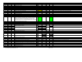
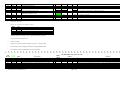
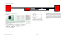
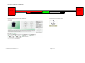
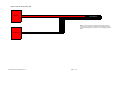
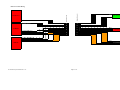
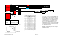
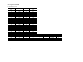
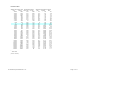
Montero Sport 1997 3.0L ECM/1999 3.5L A/T PCM Pin-Out Table for Piggy-Back AEM F/IC 8 & Innovate LC-1 WBO2
Pin-outs were taken directly from the official Mitsubishi™ factory service manuals and as such may contain errors if the service manual documentation is in error. Not all pin-outs may be listed in the tables below. Note that these pin-outs are untested and use of these tables may result in vehicle component damage. As such, the user
of this documentation accepts all liability and may not hold the distributor of this document liable for any damages that may occur. Do not attempt to use these tables without confirming that the pin-outs are correct!
1997 M/T ECM FED MD338139/MD349089 (GREEN 76-pin)
1-20 -- inj 7 IN ---------- 12-24 inj 3 IN
3-20 -- inj 7 OUT ---------- 20-24 inj 3 OUT
1999 A/T PCM FED MD357516/MD364531 (BLACK 119-pin
1999
BLACK
1
9
24
2
10
25
3
6
11
12
13
14
28
15
29
34
18
1997
GREEN
1
14
2
15
3
16
34
6
10
23
11
4
17
5
18
32
none
19
20
21
22
26
35
46
45
44
43
41
47
48
19
8
22
36
42
41
81
89
83
51
12
25
13
16
17
16
42
26
16
56
88
3
AWG
16
16
16
16
16
16
18
18
18
F/IC 8 IN
ECM/PCM Pin Description
No. 1 fuel injector (A-75)
No. 2 fuel injector (A-72)
No. 3 fuel injector (A-74)
No. 4 fuel injector (A-71)
No. 5 fuel injector (A-73)
No. 6 fuel injector (A-70)
Heated oxygen sensor heater (front) FED
EGR solenoid FED
Ignition power transistor unit A
Ignition power transistor unit B
Ignition power transistor unit C
Stepper motor coil <A1>
Stepper motor coil <A2>
Stepper motor coil <B1>
Stepper motor coil <B2>
Evaporative emission purge solenoid
Condenser fan relay
Volume air flow sensor reset signal
Fuel pump relay module
A/C compressor clutch relay
Service engine soon/malfunction indicator lamp
Heated oxygen sensor heater (rear) FED
Evaporative emission ventilation solenoid
Sensor supplied voltage
Crankshaft position sensor
Engine coolant temperature sensor
Spark check signal (RPM signal?)
Power supply (ignition switch: "ON")
Power supply & ignition switch-IG circuit GND (body GND #3,
#10)
Camshaft position sensor
4x4 Extreme Sports ©1999-2014 v1.4
1, 7
1-22
12-22
12-24
24-24
11-24
23-24
1997 M/T ECM & 1999 A/T PCM
F/IC 8
LC-1
?CM I/O
OUT
22-24
21-24
20-24
19-24
18-24
17-24
input
NOTES4
F/IC pin 1,12,12,24,11,23/ECU, F/IC pin 22,21,20,19,18,17/injectors
input
2
output
output
output
input
input
input
input
input
7
7-22
14-22
16-22
4-22
N/A
N/A
N/A
5, 7
7
7
15-22, 1322
8-24
output
output
output
F/IC pin 7/crank sensor, F/IC pin 14/ECU
red
blue,
black
LC-1 12+, fused with at least a 5A fuse; Innovate SSI-4 12+; switched 12V source on as soon as the ignition on the car is on
Fuel Injectors, MFI Relay, Backup power supply GND; F/IC 13-22 User Switch Input switch to GND (see below for alternative); LC-1 black
calibration wire, momentary switch to GND; Innovate SSI-4 GND
N/A
3-22
output
Page 1 of 13
F/IC pin 8/cam sensor, F/IC pin 3/ECU
http://www.4x4extremesports.com/
55
52
49
66
65
64
61
59
58
71
73
78
79
80
83
85
84
57
85
37
38
80
90
72
none
91
71
76
79
84
87
86
45
62
56
92
91
92
98
50
75
77
89
76
88
97
101
102
103
104
106
74
77
82
N/A
N/A
N/A
N/A
N/A
N/A
N/A
N/A
N/A
N/A
N/A
N/A
107
N/A
Torque converter clutch solenoid valve
108
109
110
113
114
120
121
N/A
N/A
N/A
N/A
N/A
N/A
N/A
122
123
124
N/A
N/A
N/A
125
N/A
Park/Neutral position switch R
Park/Neutral position switch 3
Park/Neutral position switch L
Data link connector circuit (connector pin 26)
Data link connector circuit (connector pin 27)
Under drive solenoid valve
Park/neutral postion switch N / "N" range light system circuit
Park/neutral position switch 2
Stoplight switch
Fluid temperature sensor
Transfer low detection switch
16
16
16
16
14
16
16
16
16
Barometric pressure sensor
Power steering pressure switch
MFI relay (power supply)
Backup power supply
Volume air flow sensor
Intake air temperature sensor
A/C switch 2
Ignition switch-ST GND (body GND #3)
Ignition switch-ST
Heated oxygen sensor (front) FED
Heated oxygen sensor (rear) FED
Throttle position sensor
Closed throttle position switch <3.0L Engine>
Vehicle speed sensor
A/C switch
Data link connector circuit (OBD connector pin 7)
Data link connector circuit (OBD connector pin 1)
Volume air flow circuit, Baro Pressure Sensor, IAT Sensor, ECT
Sensor, TPS Sensor, O2 Sensor (front), O2 Sensor (rear), Evap
Emission Control System Pressure Sensor, Closed throttle
position switch, MAP Sensor, Fluid temp sensor <A/T>, Input
shaft speed sensor <A/T>, Output shaft speed sensor <A/T> GND
input
7
14-24
15-24
output
output
F/IC pin 14/MAF sensor, F/IC pin 15/ECU
7,8
13-24
1-24
6-22
N/A
input
input
input
output
output
input
F/IC should not require resistor noted in AEM documentation
N/A
N/A
5-22, 2020
N/A
N/A
N/A
7,8
7
7
N/A
Manifold differential pressure sensor
Fuel tank differential pressure sensor
Ignition switch-IG
A/T control relay
Auto-cruise signal line system circuit
Solenoid valve power supply
F/IC should not require resistor noted in AEM documentation
N/A
N/A
white,
green
Data link connector (1)
Data link connector (1)
LC-1 sensor GND; Delphi IAT Air Charge Temp Sensor GND; LC-1 analog GND, only present on 7 wire models
input
Body GND (#3)
Park/Neutral position switch P
Park/Neutral position switch D
Input shaft speed sensor
Output shaft speed sensor
Second solenoid valve
17
4x4 Extreme Sports ©1999-2014 v1.4
N/A
N/A
N/A
N/A
N/A
N/A
Page 2 of 13
Data link connector (2) C-82 12-pin PCM flash pin 26
Data link connector (2) C-82 12-pin INVECS-II pin 27
http://www.4x4extremesports.com/
126
129
130
N/A
N/A
N/A
Pattern select switch
Low-reverse solenoid valve
Overdrive solenoid valve
N/A
N/A
N/A
N/A
Intake air temperature sensor (IAT)
AEM F/IC User Switch Input connection (internal data
logging/dual callibration mode)
N/A
N/A
N/A
N/A
Firing order 1-2-3-4-5-6
2
Unit A - cyl 1,2; Unit B - cyl 3,4; Unit C - cyl 5,6
3
AWG
14
16
17
18
20
7
7
AEM F/IC AUX IN
1
7,9
20-20
13-22
N/A
N/A
N/A
N/A
18-22
N/A
N/A
yellow
brown
F/IC AUX Analog C; GM Delphi IAT Air Charge Temp Sensor
F/IC User Switch Input switch to GND, lug body GND #3 (or see above for alternative)
LC-1 analog out 1 (O2 NB)
LC-1 analog out 2 (O2 WB), 0V=7.35 AFR and 5V=22.39 AFR; 14.7 Stoichiometric, 13.5 max torque
mm2
2.00
1.25
0.85
0.75
0.50
unless otherwise noted, wire gauge is 20 AWG (0.5 mm 2 )
4
Mitsubishi specific notes apply to 1997 5-speed ECM and wiring harness'
5
B+ power on durring IG ON and ST
6
confirm in manual
7
AEM F/IC pin and plug number. Example: 1-24 is pin 1 on the 24 pin plug
8
2
Not necessary unless changing fuel delivery by modifying O
sensor signal
9
Not necessary unless an independant IAT source is required
1997 M/T ECM & 2001-2004? A/T PCM
1999
BLACK
7
20
21
50
51
59
60
75
76
1997
GREEN
none
22
8
none
none
91
none
none
none
AWG
Description
MS III /
MS3X
?CM I/O
A/T fluid temperature warning light <V4A51> <A/T>
A/C compressor clutch relay
Fuel pump relay module
A/T Control Relay System GND <A/T>
Fuel temperature sensor (Fuel temperature sensor circuit)
Park/neutral position switch <A/T>
Fuel gauge unit (Fuel level sensor circuit)
Auto-cruise signal line system circuit
GND
4x4 Extreme Sports ©1999-2014 v1.4
NOTES
run wire from fuel level/temperature sensor pin 1 <00-04 fuel temperature signal/sensor>
tap from fuel gauge circuit <97-04 fuel level signal/sensor pin 2>
Page 3 of 13
http://www.4x4extremesports.com/
77
89
88
97
96
103
104
110
122
109
102
121
108
101
120
106
130
107
129
123
124
112
111
none
none
none
none
none
none
none
none
none
none
none
none
none
none
none
none
none
none
none
none
none
none
none
A/T Control Relay System (solenoid valve PS) <A/T>
GND
Fuel level warning light
Input shaft speed sensor system <A/T>
Output shaft speed sensor system <A/T>
Park/Neutral Position Switch System (L) <A/T>
Park/Neutral Position Switch System (2) <A/T>
Park/Neutral Position Switch System (3) <A/T>
Park/Neutral Position Switch System (D) <A/T>
Park/Neutral Position Switch System (N) <A/T>
Park/Neutral Position Switch System (R) <A/T>
Park/Neutral Position Switch System (P) <A/T>
Low/Reverse solenoid system valve circuit (underdrive) <A/T>
Low/Reverse solenoid system valve circuit (second) <A/T>
Low/Reverse solenoid system valve circuit (overdrive) <A/T>
Low/Reverse solenoid system valve circuit (torque converter clutch) <A/T>
Low/Reverse solenoid system valve circuit (low & reverse) <A/T>
Stoplight switch system circuit <A/T>
A/T fluid temperature sensor system circuit <A/T>
Transfer low detection switch <V4A51> <A/T>
Immobilizer/PCM communications line
4x4 Extreme Sports ©1999-2014 v1.4
intercept fuel level warning light signal/sensor pin 1 <97-99>
PCM/immobilizer control module must come from same vehicle/additional parts and wiring required
Page 4 of 13
http://www.4x4extremesports.com/
AEM F/IC User Switch Input
AEM F/IC
>>>>
>>>> User Switch Input 13-22 >>>>
Switch (NO,
Illuminated)
LED (a)
Resistor
Pin 26
ECM/PCM
Resistor
LED (k)
Push-Button Switch 2P SPST OFF-ON RED LED
LED Resistor *
Green
25mA - 2.2V
470 ohm 1/2w
120 ohm 1/8w
13.87v
5.0v
Red
30mA - 1.7V
470 ohm 1w
120 ohm 1/4w
13.87v
5.0v
Notes: When the User Switch Input from he F/IC is grounded, the
F/IC will be in either internal logging mode or operating from
calibration two in dual-calibration mode. The switch LED will be
off when the circuit is open (no logging/calibration one) and on
when closed (logging/calibration two). With the switch and LED
configured in this way, care should be taken to make sure that the
+ and - side of the switch are not reversed or the LED will be
damaged. Operation: press to enable logging/calibration two
(LED ON), press again to disable logging/revert to calibration one
(LED OFF).
* Resistor may or may not be required
depending on type of switch used. Resistor
values depend on LED used, confirm
correct values. Metal film axial 5% resistor.
Shin Chin PN# R13-529BL-05-BRR
4x4 Extreme Sports ©1999-2014 v1.2
Page 5 of 13
http://www.4x4extremesports.com/
Innovate LC-1 Indicator and Calibration
AEM F/IC
>>>> black >>>>
(LP1 Pin 2)
LED (a) / (LP1 Pin 3)
Push-Button Switch 2P SPST OFF-(ON) GREEN LED
Momentary Switch
(NO, Illuminated)
(LP1 Pin 4)
Pin 13
ECM/PCM
LED (k) / (LP1 Pin 1)
E-Switch Series LP1 Momentary Switch
Shin Chin PN# R13-529AL-05-BGG
4x4 Extreme Sports ©1999-2014 v1.1
Page 6 of 13
http://www.4x4extremesports.com/
Engine Intake Air Temperature (IAT)
AEM F/IC
>>>> AUX Analog C 20-20 >>>>
IAT (GM/Delphi)
Notes: This is a method for collecting independent Intake Air
Temperature (IAT) data by the AEM F/IC for logging purposes.
The F/IC DOES NOT use IAT data - this is for logging purposes
ONLY.
ECM/PCM
4x4 Extreme Sports ©1999-2014 v1.3
<<<< Pin 92 <<<<
Page 7 of 13
http://www.4x4extremesports.com/
External Controls Wiring
<<<< Pin 13 <<<<
Female Connector
>>>> Black >>>>
>>>>
Male Connector
Innovate LC-1
A
A
B
B
C
C
>>>>
D
D
<<<<
E
E
F
F
<<<<
ECM/PCM
Momentary Switch
(NO, Illuminated)
Switch (NO,
Illuminated)
<<<< Pin 26 WH <<<<
<<<< Pin 92 <<<<
>>>> Pin 13-22 WH >>>>
>>>> 20-20 >>>>
<<<<
IAT (GM/Delphi)
AEM F/IC
>>>>
4x4 Extreme Sports ©1999-2014 v1.0
Page 8 of 13
http://www.4x4extremesports.com/
Innovate SSI-4 Sensor Interface - MAP
+5 V
+5 Vref
-5 V GND
GND
MAP (GM/Delphi)
CH4Innovate SSI-4
Sensor output
CH4+
12 V GND
+12 V
Serial In
Serial Out
Serial Out
Serial In
LC-1/2 WBO2
Serial/USB
Innovate OT-2
Laptop Logworks,
Innovate PL-1
OBD-II
Connector
Pin 12
Pin 13
Notes: This is one example in which to gather Manifold Air
Pressure (MAP) data and stream the data to a logging device
such as a laptop, PC or Innovate device such as the PL-1 for latte
analysis, as Mitsubishi does not supply MAP data via OBD-II. The
SSI-4 supports up to four sensors. A second MAP sensor may be
configured to collect Barometric Pressure (BARO) data. Channel
4 on the SSI-4 device is used as an example only for simplicities'
sake; the first two channels are pre-configured by Innovate for
other purposes. All channels may be reconfigured by the user via
Innovate's configuration tool. The Innovate LMA-1 and DS-32
have built-in MAP sensors and either may be substituted for the
SSI-4. In this case, a separate MAP sensor would only be
necessary to collect BARO data. Operation: To generate timing
maps via Logworks, its necessary to chain the SSI-4 to Innovate's
OT-2 OBD-II data collection device. The OT-2 supplies the
necessary timing and RPM data collected from the ECM and the
SSI-4 supplies MAP. In Logworks, configure the x axis as RPM,
the y axis as MAP and plot Timing.
ECM/PCM
2 Pin Weather Pack Connector
Part #
Description
SNSR-03056
Delphi / GM 1 Bar Map Sensor
CONN-75558
GM Delphi / Packard - 1 bar MAP
Sensor Connector Kit
http://www.bmotorsports.com/shop/product_info.php/products_id/1583
OT-2 Notes: Configure the following OBD-II PIDS in the OT-2 to
collect RPM and Timing: RPM, SparkAdv. DO NOT configure
these PIDs for Low Priority.
http://www.robietherobot.com/storm/mapsensor.htm
Pin A: GND
Pin B: Sensor output
Pin C: +5 Vref
4x4 Extreme Sports ©1999-2014 v1.6
Page 9 of 13
http://www.4x4extremesports.com/
1997 Mitsubishi Montero Sport 3.0L ECM M/T & A/T
4x4 Extreme Sports ©1999-2013 v1.0
Page 10 of 13
http://www.4x4extremesports.com/
1999 Mitsubishi Montero Sport 3.5L PCM A/T
4x4 Extreme Sports ©1999-2013 v1.0
Page 11 of 13
http://www.4x4extremesports.com/
Wire Gauge Conversion Table
No code indicates 0.5 mm2
American Wire Gauge
(AWG)
0
0
0
0
1
2
3
4
5
6
7
8
9
10
11
12
13
14
15
16
17
18
19
20
21
22
23
24
25
26
Diameter (in)
AWG
30
28
26
24
22
21
20
mm2
0.05
0.08
0.14
0.25
0.34
0.38
0.5
0.46
0.4096
0.3648
0.3249
0.2893
0.2576
0.2294
0.2043
0.1819
0.162
0.1443
0.1285
0.1144
0.1019
0.0907
0.0808
0.072
0.0641
0.0571
0.0508
0.0453
0.0403
0.0359
0.032
0.0285
0.0254
0.0226
0.0201
0.0179
0.0159
4x4 Extreme Sports ©1999-2013 v1.0
Diameter (mm) Cross Sectional Area
(mm2)
11.68
107.16
10.4
84.97
9.27
67.4
8.25
53.46
7.35
42.39
6.54
33.61
5.83
26.65
5.19
21.14
4.62
16.76
4.11
13.29
3.67
10.55
3.26
8.36
2.91
6.63
2.59
5.26
2.3
4.17
2.05
3.31
1.83
2.63
1.63
2.08
1.45
1.65
1.29
1.31
1.15
1.04
1.02
0.82
0.91
0.65
0.81
0.52
0.72
0.41
0.65
0.33
0.57
0.26
0.51
0.2
0.45
0.16
0.4
0.13
AWG
18
17
16
14
12
10
8
mm2
0.75
1
1.5
2.5
4
6
10
AWG
6
4
2
1
1/0
2/0
3/0
mm2
16
25
35
50
55
70
95
AWG
4/0
300MCM
350MCM
500MCM
600MCM
750MCM
1000MCM
Page 12 of 13
mm2
120
150
185
240
300
400
500
http://www.4x4extremesports.com/
Pressure Table
Altitude Above Sea Level Absolute Barometer
feet
meters
inches Hg mm Hg
-5000
-1524
35.7
908
-4500
-1372
35.1
892
-4000
-1219
34.5
876
-3500
-1067
33.9
861
-3000
-914
33.3
846
-2500
-762
32.7
831
-2000
-610
32.1
816
-1500
-457
31.6
802
-1000
-305
31
788
-500
-152
30.5
774
01
0
29.9
760
500
152
29.4
746
1000
305
28.9
733
1500
457
28.3
720
2000
610
27.8
707
2500
762
27.3
694
3000
914
26.8
681
3500
1067
26.3
669
4000
1219
25.8
656
4500
1372
25.4
644
5000
1524
24.9
632
6000
1829
24
609
7000
2134
23.1
586
8000
2438
22.2
564
9000
2743
21.4
543
10000
3048
20.6
523
15000
4572
16.9
429
20000
6096
13.8
349
25000
7620
11.1
282
30000
9144
8.89
226
35000
10668
7.04
179
40000
12192
5.52
140
45000
13716
4.28
109
50000
15240
3.27
83
1
Absolute Atmospheric Pressure
psia
kg/cm2
kPa
17.5
1.23
121
17.2
1.21
119
16.9
1.19
117
16.6
1.17
115
16.4
1.15
113
16.1
1.13
111
15.8
1.11
109
15.5
1.09
107
15.2
1.07
105
15
1.05
103
14.7
1.03
101
14.4
1.01
99.5
14.2
0.997
97.7
13.9
0.979
96
13.7
0.961
94.2
13.4
0.943
92.5
13.2
0.926
90.8
12.9
0.909
89.1
12.7
0.893
87.5
12.5
0.876
85.9
12.2
0.86
84.3
11.8
0.828
81.2
11.3
0.797
78.2
10.9
0.768
75.3
10.5
0.739
72.4
10.1
0.711
69.7
8.29
0.583
57.2
6.75
0.475
46.6
5.45
0.384
37.6
4.36
0.307
30.1
3.46
0.243
23.8
2.71
0.191
18.7
2.1
0.148
14.5
1.61
0.113
11.1
- Sea Level
(Source unknown)
4x4 Extreme Sports ©1999-2014 v1.0
Page 13 of 13
http://www.4x4extremesports.com/