1
TMS320DM6446 DVEVM v2.0
Getting Started Guide
Literature Number: SPRUE66E
December 2008
IMPORTANT NOTICE
Texas Instruments Incorporated and its subsidiaries (TI) reserve the right to make corrections, modifications,
enhancements, improvements, and other changes to its products and services at any time and to discontinue any
product or service without notice. Customers should obtain the latest relevant information before placing orders
and should verify that such information is current and complete. All products are sold subject to TI's terms and
conditions of sale supplied at the time of order acknowledgment.
TI warrants performance of its hardware products to the specifications applicable at the time of sale in accordance
with TI's standard warranty. Testing and other quality control techniques are used to the extent TI deems necessary
to support this warranty. Except where mandated by government requirements, testing of all parameters of each
product is not necessarily performed.
TI assumes no liability for applications assistance or customer product design. Customers are responsible for their
products and applications using TI components. To minimize the risks associated with customer products and
applications, customers should provide adequate design and operating safeguards.
TI does not warrant or represent that any license, either express or implied, is granted under any TI patent right,
copyright, mask work right, or other TI intellectual property right relating to any combination, machine, or process
in which TI products or services are used. Information published by TI regarding third-party products or services
does not constitute a license from TI to use such products or services or a warranty or endorsement thereof. Use
of such information may require a license from a third party under the patents or other intellectual property of the
third party, or a license from TI under the patents or other intellectual property of TI.
Reproduction of information in TI data books or data sheets is permissible only if reproduction is without alteration
and is accompanied by all associated warranties, conditions, limitations, and notices. Reproduction of this information with alteration is an unfair and deceptive business practice. TI is not responsible or liable for such altered
documentation.
Resale of TI products or services with statements different from or beyond the parameters stated by TI for that
product or service voids all express and any implied warranties for the associated TI product or service and is an
unfair and deceptive business practice. TI is not responsible or liable for any such statements.
Following are URLs where you can obtain information on other Texas Instruments products and application solutions:
Products
Amplifiers
Applications
amplifier.ti.com
Audio
www.ti.com/audio
Data Converters
dataconverter.ti.com
Automotive
www.ti.com/automotive
DSP
dsp.ti.com
Broadband
www.ti.com/broadband
Interface
interface.ti.com
Digital Control
www.ti.com/digitalcontrol
Logic
logic.ti.com
Military
www.ti.com/military
Power Mgmt
power.ti.com
Optical Networking
www.ti.com/opticalnetwork
Microcontrollers
microcontroller.ti.com
Security
www.ti.com/security
Low Power Wireless
www.ti.com/lpw
Mailing Address:
Telephony
www.ti.com/telephony
Video & Imaging
www.ti.com/video
Wireless
www.ti.com/wireless
Texas Instruments
Post Office Box 655303 Dallas, Texas 75265
Copyright © 2008, Texas Instruments Incorporated
EVALUATION BOARD/KIT IMPORTANT NOTICE
Texas Instruments (TI) provides the enclosed product(s) under the following conditions:
This evaluation board/kit is intended for use for ENGINEERING DEVELOPMENT, DEMONSTRATION, OR EVALUATION PURPOSES ONLY and is not considered by TI to be a finished
end-product fit for general consumer use. Persons handling the product(s) must have electronics
training and observe good engineering practice standards. As such, the goods being provided
are not intended to be complete in terms of required design-, marketing-, and/or manufacturingrelated protective considerations, including product safety and environmental measures typically
found in end products that incorporate such semiconductor components or circuit boards. This
evaluation board/kit does not fall within the scope of the European Union directives regarding
electromagnetic compatibility, restricted substances (RoHS), recycling (WEEE), FCC, CE or UL,
and therefore may not meet the technical requirements of these directives or other related
directives.
Should this evaluation board/kit not meet the specifications indicated in the User's Guide, the
board/kit may be returned within 30 days from the date of delivery for a full refund. THE FOREGOING WARRANTY IS THE EXCLUSIVE WARRANTY MADE BY SELLER TO BUYER AND
IS IN LIEU OF ALL OTHER WARRANTIES, EXPRESSED, IMPLIED, OR STATUTORY, INCLUDING ANY WARRANTY OF MERCHANTABILITY OR FITNESS FOR ANY PARTICULAR
PURPOSE.
The user assumes all responsibility and liability for proper and safe handling of the goods.
Further, the user indemnifies TI from all claims arising from the handling or use of the goods.
Due to the open construction of the product, it is the user's responsibility to take any and all
appropriate precautions with regard to electrostatic discharge.
EXCEPT TO THE EXTENT OF THE INDEMNITY SET FORTH ABOVE, NEITHER PARTY
SHALL BE LIABLE TO THE OTHER FOR ANY INDIRECT, SPECIAL, INCIDENTAL, OR CONSEQUENTIAL DAMAGES.
TI currently deals with a variety of customers for products, and therefore our arrangement with
the user is not exclusive.
TI assumes no liability for applications assistance, customer product design, software
performance, or infringement of patents or services described herein.
Please read the User's Guide and, specifically, the Warnings and Restrictions notice in the User's
Guide prior to handling the product. This notice contains important safety information about
temperatures and voltages. For additional information on TI's environmental and/or safety programs, please contact the TI application engineer or visit www.ti.com/esh.
No license is granted under any patent right or other intellectual property right of TI covering or
relating to any machine, process, or combination in which such TI products or services might
be or are used.
Mailing Address:
Texas Instruments
Post Office Box 655303
Dallas, Texas 75265
Copyright © 2008, Texas Instruments Incorporated
FCC Warning
This evaluation board/kit is intended for use for ENGINEERING DEVELOPMENT, DEMONSTRATION, OR EVALUATION PURPOSES ONLY and is not considered by TI to be a finished
end-product fit for general consumer use. It generates, uses, and can radiate radio frequency
energy and has not been tested for compliance with the limits of computing devices pursuant
to part 15 of FCC rules, which are designed to provide reasonable protection against radio
frequency interference. Operation of this equipment in other environments may cause interference with radio communications, in which case the user at his own expense will be required to
take whatever measures may be required to correct this interference.
This is a draft version printed from file: pref.fm on 12/18/08
Preface
About This Guide
The DVEVM (Digital Video Evaluation Module) kit is an evaluation
platform that showcases the DM644x architecture and lets users
evaluate the power and performance of the DM644x as a multimedia
engine.
This guide gives you overview information about the board and the
software provided with the board. It is intended to be used as an
introductory document for the DVEVM. Other documents provide more
in-depth information. See the DVEVM release notes for a complete list of
documents that have been included with the product.
Additional Documents and Resources
You can use the following sources to supplement this user’s guide:
❏
Spectrum Digital website:
http://c6000.spectrumdigital.com/davincievm
❏
TI Linux Community for DaVinci Processors:
http://linux.davincidsp.com
❏
TI DaVinci Software Updates: http://www.ti.com/dvevmupdates
❏
TI DaVinci Technology Developers Wiki: http://wiki.davincidsp.com
❏
Codec Engine Application Developer's Guide (SPRUE67)
❏
Other PDF documents included with the DVEVM kit
❏
Section 4.11 lists documentation in the DVSDK software installation.
❏
SoC Analyzer Help menu
v
Notational Conventions
Notational Conventions
This document uses the following conventions:
❏
Program listings, program examples, and interactive displays are
shown in a mono-spaced font. Examples use bold for emphasis,
and interactive displays use bold to distinguish commands that you
enter from items that the system displays (such as prompts,
command output, error messages, etc.).
❏
Square brackets ( [ and ] ) identify an optional parameter. If you use
an optional parameter, you specify the information within the
brackets. Unless the square brackets are in a bold typeface, do not
enter the brackets themselves.
Trademarks
The Texas Instruments logo and Texas
Instruments are registered trademarks of Texas
Instruments. Trademarks of Texas Instruments
include: TI, DaVinci, the DaVinci logo, XDS, Code
Composer, Code Composer Studio, Probe Point,
Code Explorer, DSP/BIOS, RTDX, Online DSP
Lab,
DaVinci,
TMS320,
TMS320C54x,
TMS320C55x, TMS320C62x, TMS320C64x,
TMS320C67x,
TMS320C5000,
and
TMS320C6000.
MS-DOS, Windows, and Windows NT are trademarks of Microsoft
Corporation.
UNIX is a registered trademark of The Open Group in the United States
and other countries.
Linux is a registered trademark of Linus Torvalds.
Solaris, SunOS, and Java are trademarks or registered trademarks of
Sun Microsystems, Inc.
All other brand, product names, and service names are trademarks or
registered trademarks of their respective companies or organizations.
December 18, 2008
vi
This is a draft version printed from file: davinci_gsgTOC.fm on 12/18/08
Contents
1
DVEVM Overview . . . . . . . . . . . . . . . . . . . . . . . . . . . . . . . . . . . . . . . . . . . . . . . . . . . . . . . . . . .1-1
This chapter introduces the DVEVM (Digital Video Evaluation Module) kit.
1.1
Welcome! . . . . . . . . . . . . . . . . . . . . . . . . . . . . . . . . . . . . . . . . . . . . . . . . . . . . . . . . . . . .1-2
1.2
What’s in this Kit? . . . . . . . . . . . . . . . . . . . . . . . . . . . . . . . . . . . . . . . . . . . . . . . . . . . . . .1-3
1.3
What’s on the Board? . . . . . . . . . . . . . . . . . . . . . . . . . . . . . . . . . . . . . . . . . . . . . . . . . . .1-4
1.4
What’s Next? . . . . . . . . . . . . . . . . . . . . . . . . . . . . . . . . . . . . . . . . . . . . . . . . . . . . . . . . .1-5
2
EVM Hardware Setup . . . . . . . . . . . . . . . . . . . . . . . . . . . . . . . . . . . . . . . . . . . . . . . . . . . . . . .2-1
This chapter tells you how to set up the EVM hardware.
2.1
Setting Up the Hardware . . . . . . . . . . . . . . . . . . . . . . . . . . . . . . . . . . . . . . . . . . . . . . . .2-2
2.2
Connecting to a Console Window . . . . . . . . . . . . . . . . . . . . . . . . . . . . . . . . . . . . . . . . .2-6
3
Running the Demonstration Software . . . . . . . . . . . . . . . . . . . . . . . . . . . . . . . . . . . . . . . . . .3-1
This chapter explains how to run the software demos provided with the DVEVM kit.
3.1
Default Boot Configuration . . . . . . . . . . . . . . . . . . . . . . . . . . . . . . . . . . . . . . . . . . . . . . .3-2
3.2
Starting the Standalone Demos . . . . . . . . . . . . . . . . . . . . . . . . . . . . . . . . . . . . . . . . . . .3-2
3.3
Running the Standalone Demos. . . . . . . . . . . . . . . . . . . . . . . . . . . . . . . . . . . . . . . . . . .3-4
3.3.1
Shutting Down the Demos . . . . . . . . . . . . . . . . . . . . . . . . . . . . . . . . . . . . . . .3-5
3.3.2
About the Encode + Decode Demo . . . . . . . . . . . . . . . . . . . . . . . . . . . . . . . .3-6
3.3.3
About the Encode Demo . . . . . . . . . . . . . . . . . . . . . . . . . . . . . . . . . . . . . . . .3-7
3.3.4
About the Decode Demo . . . . . . . . . . . . . . . . . . . . . . . . . . . . . . . . . . . . . . . .3-8
3.3.5
About the Third Party Menu . . . . . . . . . . . . . . . . . . . . . . . . . . . . . . . . . . . . . .3-9
3.4
Running the Demos from the Command Line . . . . . . . . . . . . . . . . . . . . . . . . . . . . . . . .3-9
3.5
Running the Network Demo . . . . . . . . . . . . . . . . . . . . . . . . . . . . . . . . . . . . . . . . . . . . .3-11
4
DVEVM Software Setup . . . . . . . . . . . . . . . . . . . . . . . . . . . . . . . . . . . . . . . . . . . . . . . . . . . . .4-1
This chapter explains how to use the software provided with the DVEVM kit.
4.1
Software Overview . . . . . . . . . . . . . . . . . . . . . . . . . . . . . . . . . . . . . . . . . . . . . . . . . . . . .4-2
4.1.1
Command Prompts in This Guide . . . . . . . . . . . . . . . . . . . . . . . . . . . . . . . . .4-3
4.1.2
Software Components . . . . . . . . . . . . . . . . . . . . . . . . . . . . . . . . . . . . . . . . . .4-4
4.2
Preparing to Install . . . . . . . . . . . . . . . . . . . . . . . . . . . . . . . . . . . . . . . . . . . . . . . . . . . . .4-5
4.3
Installing the Software . . . . . . . . . . . . . . . . . . . . . . . . . . . . . . . . . . . . . . . . . . . . . . . . . .4-5
4.3.1
Installing the Target Linux Software . . . . . . . . . . . . . . . . . . . . . . . . . . . . . . . .4-6
4.3.2
Installing the DVSDK Software. . . . . . . . . . . . . . . . . . . . . . . . . . . . . . . . . . . .4-7
4.3.3
Installing the A/V Demo Files . . . . . . . . . . . . . . . . . . . . . . . . . . . . . . . . . . . . .4-8
4.3.4
Installing the SoC Analyzer . . . . . . . . . . . . . . . . . . . . . . . . . . . . . . . . . . . . . .4-9
vii
Contents
4.4
4.5
4.6
4.7
4.8
4.9
4.10
4.11
A
Additional Procedures . . . . . . . . . . . . . . . . . . . . . . . . . . . . . . . . . . . . . . . . . . . . . . . . . . . . . . A-1
This appendix describes optional procedures you may use depending on your setup and specific
needs.
A.1
A.2
A.3
A.4
A.5
A.6
viii
4.3.5
Exporting a Shared File System for Target Access . . . . . . . . . . . . . . . . . . . 4-9
4.3.6
Testing the Shared File System . . . . . . . . . . . . . . . . . . . . . . . . . . . . . . . . . 4-11
4.3.7
Configuring the Boot Setup for PAL Video Users . . . . . . . . . . . . . . . . . . . . 4-12
4.3.8
Notes on Using Evaluation/Production Codecs . . . . . . . . . . . . . . . . . . . . . 4-12
Setting Up the Build/Development Environment . . . . . . . . . . . . . . . . . . . . . . . . . . . . . 4-13
4.4.1
Writing a Simple Program and Running it on the EVM . . . . . . . . . . . . . . . . 4-13
Building a New Linux Kernel . . . . . . . . . . . . . . . . . . . . . . . . . . . . . . . . . . . . . . . . . . . . 4-14
Rebuilding the DVEVM Software for the Target . . . . . . . . . . . . . . . . . . . . . . . . . . . . . 4-16
Booting the New Linux Kernel . . . . . . . . . . . . . . . . . . . . . . . . . . . . . . . . . . . . . . . . . . . 4-17
Testing the Build Environment . . . . . . . . . . . . . . . . . . . . . . . . . . . . . . . . . . . . . . . . . . 4-18
Using the Digital Video Test Bench (DVTB) . . . . . . . . . . . . . . . . . . . . . . . . . . . . . . . . 4-18
Running The SoC Analyzer. . . . . . . . . . . . . . . . . . . . . . . . . . . . . . . . . . . . . . . . . . . . . 4-20
Documentation for DSP-Side Development . . . . . . . . . . . . . . . . . . . . . . . . . . . . . . . . 4-21
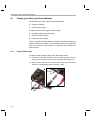
Changing the Video Input/Output Methods . . . . . . . . . . . . . . . . . . . . . . . . . . . . . . . . . . . . . . . . . A-2
Putting Demo Applications in the Third-Party Menu. . . . . . . . . . . . . . . . . . . . . . . . . . . . . . . . . . . A-5
Setting Up a TFTP Server . . . . . . . . . . . . . . . . . . . . . . . . . . . . . . . . . . . . . . . . . . . . . . . . . . . . . . A-7
Alternate Boot Methods . . . . . . . . . . . . . . . . . . . . . . . . . . . . . . . . . . . . . . . . . . . . . . . . . . . . . . . . A-8
Rebuilding DSP/BIOS Link. . . . . . . . . . . . . . . . . . . . . . . . . . . . . . . . . . . . . . . . . . . . . . . . . . . . . A-11
Restoring and Updating the EVM Hard Disk Drive. . . . . . . . . . . . . . . . . . . . . . . . . . . . . . . . . . . A-12
Chapter 1
DVEVM Overview
This chapter introduces the DVEVM (Digital Video Evaluation Module)
kit.
Topic
Page
1.1
Welcome! . . . . . . . . . . . . . . . . . . . . . . . . . . . . . . . . . . . . . . . . . . . . . . . 1–2
1.2
What’s in this Kit? . . . . . . . . . . . . . . . . . . . . . . . . . . . . . . . . . . . . . . . . 1–3
1.3
What’s on the Board? . . . . . . . . . . . . . . . . . . . . . . . . . . . . . . . . . . . . . 1–4
1.4
What’s Next? . . . . . . . . . . . . . . . . . . . . . . . . . . . . . . . . . . . . . . . . . . . . 1–5
1-1
Welcome!
1.1
Welcome!
Your new DVEVM (Digital Video Evaluation
Module) kit will allow you to evaluate TI’s new
DaVinciTM Technology and the DM644x
architecture.
This technology brings together system-solution
components tailored for efficient and compelling
digital video and audio.
1-2
What’s in this Kit?
1.2
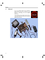
What’s in this Kit?
Your DVEVM kit contains the following hardware items. Section 2.1,
Setting Up the Hardware tells how to connect these components.
❏
EVM Board. This board contains a DaVinci TMS320DM6446 dualcore device with an ARM9 and C64+ DSP for development of
applications that use both a general-purpose processor and an
accelerated DSP processor.
❏
Hard Disk Drive. The hard drive provided with the EVM is a 2.5"
Spinpoint drive with 40 GB of storage. The drive speed in 5400 RPM
and it has an 8MB cache. The drive is an Ultra ATA 66/100/133 IDE.
Software has been preloaded on this EVM board’s hard disk drive.
❏
CCD Camera. This camera provides NTSC or PAL video imaging for
DaVinci applications.
❏
LCD Display. The LCD display provided with the DVEVM kit has a
5.6" screen and 320x240 pixels. Cables and a power supply are
provided. The NTSC version has a 110 VAC power supply. The PAL
version has a 220 VAC power supply.
❏
PC Desktop Microphone. The microphone provides a way to
capture audio for use by DaVinci applications.
❏
IR Remote Control. This universal remote control is included to
provide a user interface to the demo applications.
❏
Cables. Cables used to connect the EVM board to peripheral
devices and to a host Linux workstation used for development are
provided in the kit.
The DVEVM kit also comes with the following software. Information about
how to use the software components is provided in Chapter 4.
❏
DaVinci Digital Video Evaluation Kit.
❏
TI DaVinci Demonstration Version of MontaVista Linux Pro v5.0
Target
❏
TI DaVinci Demonstration Version of MontaVista Linux Pro v5.0
Tools
❏
A/V Media Clips
❏
Spectrum Digital EVM Tools
❏
SoC Analyzer
DVEVM Overview
1-3
What’s on the Board?
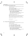
1.3
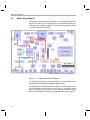
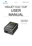
What’s on the Board?
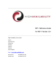
The EVM comes loaded with peripherals your multimedia applications
may need to make use of. The hard drive on the board also comes preloaded with demonstration software. The following block diagram shows
the major hardware components.
Diagram provided courtesy of Spectrum Digital Inc.
Figure 1–1 EVM Hardware Block Diagram
For more information about the EVM hardware, see the DaVinci EVM
website at http://c6000.spectrumdigital.com/davincievm.
The DaVinci EVM incorporates a battery holder to provide backup power
to the MSP430’s real-time clock when the power is not applied to the
board. The battery is not included in the kit. See the Spectrum Digital
DaVinci EVM Technical Reference for suggested battery part numbers.
1-4
What’s Next?
1.4
What’s Next?
To get started evaluating the DVEVM kit and developing applications for
the DM644x, begin by using this Getting Started guide. It will step you
through connecting the hardware, testing the software, and beginning to
develop applications.
When you are ready for more information about DaVinci Technology and
the DM644x architecture, see the following:
❏
Spectrum Digital website:
http://c6000.spectrumdigital.com/davincievm
❏
TI Linux Community for DaVinci Processors:
http://linux.davincidsp.com
❏
TI DaVinci Software Updates: http://www.ti.com/dvevmupdates
❏
TI DaVinci Technology Developers Wiki: http://wiki.davincidsp.com
❏
Codec Engine Application Developer's Guide (SPRUE67)
❏
Other PDF documents included with the DVEVM kit
❏
Section 4.11 lists documentation in the DVSDK software installation.
❏
SoC Analyzer Help menu
DVEVM Overview
1-5
1-6
Chapter 2
EVM Hardware Setup
This chapter tells you how to set up the EVM hardware.
Topic
Page
2.1
Setting Up the Hardware . . . . . . . . . . . . . . . . . . . . . . . . . . . . . . . . . . . 2–2
2.2
Connecting to a Console Window . . . . . . . . . . . . . . . . . . . . . . . . . . . 2–6
2-1
Setting Up the Hardware
2.1
Setting Up the Hardware
To set up the hardware provided with the EVM, use the steps in the
sections that follow. You may skip sections if you do not need to access
a particular peripheral. For example, if you do not need to use the serial
cable, skip that section.
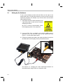
1) The EVM is sensitive to static discharges. Use
a grounding strap or other device to prevent
damaging the board.
Be sure to connect communication cables
before applying power to any equipment.
2) If you use PAL video, set switch 10 on the S3 (USER) bank of
switches to On. If you use NTSC video, set this switch to Off. See
Figure 1–1 for S3 switch bank location.
3) Connect the yellow video cable to the upper-right Video Out jack on
the EVM and the LCD display Video Input as shown below.
See Section A.1, Changing the Video Input/Output Methods for
information about using S-Video or Component video.
2-2
Setting Up the Hardware
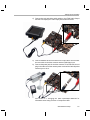
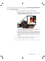
4) Connect the red and white audio cables to the EVM Audio Output
and the LCD display R/L Audio Input jacks as shown below:
5) Connect the BNC-to-RCA connector to the coax cable. Then connect
the coax cable to the video camera and the EVM Video Input.
6) Connect the power jack for the video camera. To be ESD safe, do not
plug in the other end of the camera power cord until the later step that
instructs you to do so.
See Section A.1, Changing the Video Input/Output Methods for
information about using S-Video or Component video.
EVM Hardware Setup
2-3
Setting Up the Hardware
7) Connect the microphone to the EVM.
8) Connect the power cable to the EVM power jack on the board. To be
ESD safe, do not plug in the other end of the cable yet.
9) If you will use the Ethernet connection, connect the Ethernet cable to
the Ethernet Port on the EVM and to an Ethernet network port.
Note that the U-Boot bootargs must include "ip=dhcp" to enable the
network connection.
2-4
Setting Up the Hardware
10) If you plan to use the UART port for a console window, connect the
RS-232 null modem cable to the EVM UART port and a COM port on
your host Linux workstation. See Section 2.2, Connecting to a
Console Window for more about using a console window.
11) Plug in the LCD display to a power supply.
12) Plug in the NTSC/PAL video camera to a power supply.
13) Connect the power cable to the EVM power jack on the board. To be
ESD safe, plug in the other end of the power cable only after you
have connected the power cord to the board.
14) Power on the LCD display.
15) Power on the EVM board.
16) The initial screen of the demo software should be displayed on the
LCD display. Use the IR remote to run the software as described in
Chapter 3.
EVM Hardware Setup
2-5
Connecting to a Console Window
2.2
Connecting to a Console Window
You can open a console window that allows you to watch and interrupt
EVM boot messages by following these steps:
1) Connect a serial cable between the serial port on the EVM and the
serial port (for example, COM1) on a PC.
2) Run a terminal session (such as Minicom on Linux or HyperTerminal
on Windows) on the workstation and configure it to connect to that
serial port with the following characteristics:
■
Bits per Second: 115200
■
Data Bits: 8
■
Parity: None
■
Stop Bits: 1
■
Flow Control: None
3) When you power on the EVM, you will see boot sequence messages.
You can press a key to interrupt the boot sequence and type
commands in the U-Boot command shell. In this guide, commands to
be typed in the U-Boot shell are indicated by an
EVM # prompt.
2-6
Chapter 3
Running the Demonstration Software
This chapter explains how to run the software demos provided with the
DVEVM kit.
Topic
Page
3.1
Default Boot Configuration. . . . . . . . . . . . . . . . . . . . . . . . . . . . . . . . . 3–2
3.2
Starting the Standalone Demos . . . . . . . . . . . . . . . . . . . . . . . . . . . . . 3–2
3.3
Running the Standalone Demos . . . . . . . . . . . . . . . . . . . . . . . . . . . . 3–4
3.4
Running the Demos from the Command Line . . . . . . . . . . . . . . . . . 3–9
3.5
Running the Network Demo . . . . . . . . . . . . . . . . . . . . . . . . . . . . . . . 3–11
3-1
Default Boot Configuration
3.1
Default Boot Configuration
Out of the box, the EVM boots from flash and starts the demos
automatically after a few seconds when you power up the board. It does
not require an NFS mount or a TFTP server to run the standard demos.
Note: The default U-Boot bootargs definition sets "ip=off", which disables
the Ethernet connection.
The out-of-the-box boot parameters are listed in Section A.4.1. The
following are alternate ways you may want to boot the board:
❏
TFTP boot with hard drive file system (Section A.4.2)
❏
Flash boot with NFS file system (Section A.4.3)
❏
TFTP boot with NFS file system (Section A.4.4)
❏
PAL video mode vs. NTSC video mode (Section 4.3.7)
To abort the standard boot, press any key in the console window (see
Section 2.2). Also see Section A.4, Alternate Boot Methods if you want to
change the boot configuration.
3.2
Starting the Standalone Demos
When you connect the EVM hardware, the pre-loaded examples run
automatically on the display. These examples encode and decode audio,
video, and speech. There are two ways to use the demos:
❏
Standalone. This is the default power-on mode. The demos run
automatically with no connection to a workstation in the default boot
configuration. This is the mode documented in the rest of this
chapter.
The standalone demo was set up by the DVSDK, which copies the
file /examples/dvevmdemo to the directory /etc/rc.d/init.d (the central
repository for startup scripts). This file is symbolically linked to
/etc/rc.d/rc3id/S88demo. When the board boots up and enters
runlevel 3, this file is executed to start the demo web server and the
demo interface.
❏
Command line. Once you have connected the EVM to a workstation
and installed the necessary software (as described in Section 4.3.1,
Installing the Target Linux Software), you can run the demos from the
board’s Linux command line. For further information on running the
demos from the command line, see the demo documentation that is
linked to by the DVSDK release notes.
Note: When you run the demos from the command line, make sure
the interface process used by the standalone mode demos is not
3-2
Starting the Standalone Demos
running. Otherwise you will see error messages raised when device
drivers fail to open.
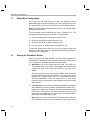
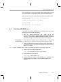
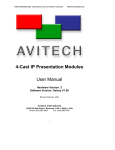
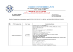
Once the EVM board has booted, the display
should show a picture of the remote control.
You use the IR remote to control the demos.
The order of the buttons on the actual remote
may be different from the picture; if your
remote looks different, find the buttons with
the same labels on your remote.
To use the demos in standalone mode, follow
these steps:
1) Check to make sure the batteries are
installed in your IR remote.
2) The initial screen shows a diagram of the
IR remote, which you use to run the
standalone demos. Take a minute to look
at the functions of the various buttons.
3) Since this is a universal remote, you may
need to set it to use the codes necessary
to run the DVEVM demos. To do this,
hold down the "Code Search" button until
the red light on the remote stays lit. Then
press the "DVD" button and enter "0020"
as the code (for older remotes shipped
with the kit, the code is "020").
4) If you accidentally put the remote in TV or
some other mode, press "DVD" to return
the remote to the correct mode.
5) If the remote does not accept the
DVD+0020 code, do a full reset by
removing the batteries, pressing the
Power button for at least a minute, then
reinserting the batteries. Then program
the remote as in Step 3.
Running the Demonstration Software
3-3
Running the Standalone Demos
3.3
Running the Standalone Demos
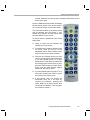
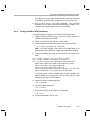
1) Press "Play" or "OK" on the remote to move from the remote control
diagram to the main menu screen, which looks like this:
The Encode + Decode demo allows you to record and playback
video. The Encode demo records audio/speech and video in the
formats you select. The Decode demo plays audio/speech and video
files you select. The Third-Party Menu can be used to add additional
demos (see Section A.2, Putting Demo Applications in the ThirdParty Menu).
2) Use the up and down arrows to change which demo is selected.
Then, press "OK" or "Play" to move to the selected demo.
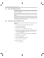
3) Within a demo, you start at the settings
screen, where you see the controls
you can use to run the demo at the
bottom of the screen and the current
settings in the upper-right.
For example, the Encode demo allows
you to set the video format and the bit
rate at which video should be encoded.
Fixed settings are also shown here.
4) Use the up and down arrows to move to a setting you want to change.
3-4
Running the Standalone Demos
5) Use the left and right arrows to cycle through the options until the
setting you want is shown.
6) Press "Play" to begin the Encode+Decode and Decode demos.
Press "Rec" (record) twice to begin the Encode demo.
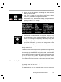
7) While the demo runs, data about the settings, processor load, and
rates are shown. Static settings are on the right. Dynamic data
reporting is on the left. For example:
8) This information overlays the video; as a result the video you see is
darker than the actual video. To hide the information display so that
you can better see the video, press the "Info/Select" button on the IR
remote. You can change the transparency of the OSD (overlay) while
running a demo by using the left and right arrows on the remote.
9) Press "Stop" or "Pause" when you want to end or pause a demo. The
first time you press "Stop", you return to the settings screen. Press
"Stop" from the settings screen to go back to the main menu.
For information about running the individual demos, see Section 3.3.2
through Section 3.3.4.
The demos use the Codec Engine to allow applications to run algorithms.
You may notice that the DSP CPU load is initially high, even if the DSP
is not running algorithms. The CPU load starts at 100% while the DSP is
booting and then decreases while the DSP waits for work to be requested
by the GPP. Even if DSP is idle, it may take a short amount of time
(several seconds) for the CPU load to settle to zero. This is because the
Codec Engine’s CPU load calculation includes a small amount of history.
3.3.1
Shutting Down the Demos
You can quit out of the demos completely while at the main menu screen
by pressing "Power" on the remote.
To restart the demos, you can reboot the board or run the demos from
the command line as described in Section 3.4.
Running the Demonstration Software
3-5
Running the Standalone Demos
3.3.2
About the Encode + Decode Demo
The Encode + Decode demo allows you to record and playback video.
Video comes from the camera, is encoded, then decoded, and then sent
to the LDC display.
The Encode + Decode does only video processing; it does not encode
and decode audio or speech. The supported video algorithm is H.264
Baseline Profile (.264 file extension).
Table 3–1 IR Remote Buttons for Encode + Decode Demo
IR Remote Button
Mode
Action Performed
Up/Down
--
-- no action --
Play or OK
Setup
Begin demo
Record
--
-- no action --
Info/Select
Setup
Show / hide block diagram for demo
Info/Select
Run
Toggle information display
Left/Right
Run
Change information transparency level
Pause
Run
Pause demo (press Play to resume)
Stop
Setup / Run
Return to previous screen
The application runs on the ARM using Linux. The video signal is passed
to video encoders and decoders on the DSP by the Codec Engine.
Shared memory is used when passing data.
To use this demo from the command line, see Section 3.4, Running the
Demos from the Command Line.
3-6
Running the Standalone Demos
3.3.3
About the Encode Demo
Like the Encode + Decode demo, the Encode demo also encodes video.
In addition, it also encodes speech. The speech source is the
microphone.
The encoded data is written to files on the EVM’s hard disk drive. The
possible filenames are demo.264, demo.mpeg4, demompeg4.g711, and
demo264.g711. Older versions of these files are overwritten as needed.
Output is not decoded and sent to the display or speakers other than to
show the settings and dynamic data collected about the load and rates.
Note that you can use only a speech encoder, not an audio encoder. The
supported video algorithms are MPEG4 (.mpeg4 file extension) and
H.264 (.264 file extension). The supported speech algorithm is G.711
(.g711 extension).
Table 3–2 IR Remote Buttons for Encode Demo
IR Remote Button
Mode
Action Performed
Up/Down
Setup
Change option selection
Left/Right
Setup
Change setting of selected option
Play
Setup
Switch to decode demo setup
Record (twice)
or OK
Setup / Run
Begin encode demo, send unencoded
data to display
Running the Demonstration Software
3-7
Running the Standalone Demos
Table 3–2 IR Remote Buttons for Encode Demo
IR Remote Button
Mode
Action Performed
Info/Select
Setup
Show / hide block diagram for demo
Info/Select
Run
Toggle information display
Left/Right
Run
Change information transparency level
(There is no display for encode demo
behind the information.)
Pause
Run
Pause demo (press Record to resume)
Stop
Setup / Run
Return to previous screen
The application runs on the ARM using Linux. The video and audio
signals are passed to encoders on the DSP by the Codec Engine. Shared
memory is used when passing data.
To use this demo from the command line, see Section 3.4, Running the
Demos from the Command Line.
3.3.4
About the Decode Demo
The Decode demo plays audio/speech and video files you select. You
can select a source video file and a source audio or speech file. Use the
left and right arrow buttons to choose from the demo files and the files
created by the Encode demo, which are stored on the EVM’s hard disk
drive. The decoded signals are sent to the display and speakers.
3-8
Running the Demos from the Command Line
The supported video algorithms are MPEG4 (.mpeg4 file extension),
H.264 (.264 file extension) and MPEG2 (.m2v file extension).
The supported audio algorithm is AAC (.aac file extension). The
supported speech algorithm is G.711 (.g711 file extension).
Table 3–3 IR Remote Buttons for Decode Demo
IR Remote Button
Mode
Action Performed
Up/Down
--
-- no action --
Left/Right
Setup
Select a different file combination
Play or OK
Setup
Begin decode demo
Record
--
-- no action --
Info/Select
Setup
Show / hide block diagram for demo
Info/Select
Run
Toggle information display
Left/Right
Run
Change information transparency level
Pause
Run
Pause demo (press Play to resume)
Stop
Setup / Run
Return to previous screen
The application runs on the ARM using Linux. The video and audio
signals are passed to decoders on the DSP by the Codec Engine. Shared
memory is used when passing data.
To use this demo from the command line, see Section 3.4, Running the
Demos from the Command Line.
3.3.5
About the Third Party Menu
The Third-Party Menu can be used to add additional demos. See Section
A.2, Putting Demo Applications in the Third-Party Menu.
3.4
Running the Demos from the Command Line
You can run the demo applications from the Linux shell in a terminal
window connected to the EVM board’s serial port. These are the same
demos described in Section 3.2, Starting the Standalone Demos.
1) See Section 2.2, Connecting to a Console Window for instructions
regarding communicating with Linux running on the EVM.
2) Login to the target as root. No password is required.
Running the Demonstration Software
3-9
Running the Demos from the Command Line
3) Move to the appropriate directory on the target using the following
command. (See Section 4.1.1 for the meanings of command prompts
shown in this document.)
Target $ cd /opt/dvsdk/dm6446
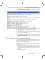
4) Before running demo applications from the command line, the CMEM
and accelerator kernel modules must be loaded.
■
Use "lsmod" to see if they are loaded. You should see output
similar to the following:
Target $ lsmod
Module
dsplinkk
cmemk
■
Size
98220
20072
Used by
0
0
If they are not loaded, use the following commands to load these
modules.
Target $ ./loadmodules.sh
5) If a standalone demo is running, kill that process. You can do this by
pressing the Power button on the remote from the main menu. Or,
use the following commands:
Target $ killall -9 interface
6) To see the command-line options for the demos, use one of the
following commands with the -h or --help option:
Target $ ./encodedecode -h
Target $ ./encode -h
Target $ ./decode -h
7) To stop a demo, press Ctrl+C at the command line or press the Stop
button on the remote.
You can also find the list of command-line options in encode.txt,
decode.txt, and encodedecode.txt in the respective demo directories of
the DVSDK package on the host.
Note: When you run loadmodules.sh, you may see warnings about
the kernel being tainted by cmemk and dsplinkk. You can ignore
these warnings. They occur because DSP/BIOS Link does not use
the kernel build system and is not under the same license as the
kernel itself.
3-10
Running the Network Demo
3.5
Running the Network Demo
As an example of standard TCP/IP networking support, the DVEVM
examples include a small HTTP web server. This web server is started
on the GPP-side as part of the Linux startup sequence. It configured to
service requests from web browsers on the standard TCP/IP port 80.
After the EVM board has booted, connect a PC to the same network to
which the EVM board is connected. Enter a URL of the form "http://ipaddress-of-evm" in a web browser (for example, Internet Explorer,
Firefox, or Opera). The IP address of the board is shown in the lower-right
corner of the main menu of the A/V demos.
You should see a web page with information about DaVinci technology
and the DVEVM software.
Use this web page to interact with the board and run the A/V demos
described in Section 3.3, Running the Standalone Demos. Two simple
CGI scripts on the EVM enable you to start the demos (assuming they are
not already running) and see what processes are running on the board.
If you want to see the demo started from the web page, be sure to exit
the demo first (use the Power button from the main menu).
The web server software is an open-source package called THTTPD
(http://www.acme.com/software/thttpd/). It is designed to be small, fast,
and portable. The source code is included with the DVEVM software. You
can get the latest version directly from the web. The web server and CGI
scripts are installed on the target in the /opt/dvsdk/dm6446/web directory.
Running the Demonstration Software
3-11
3-12
Chapter 4
DVEVM Software Setup
This chapter explains how to use the software provided with the DVEVM
kit.
Topic
Page
4.1
Software Overview . . . . . . . . . . . . . . . . . . . . . . . . . . . . . . . . . . . . . . . 4–2
4.2
Preparing to Install . . . . . . . . . . . . . . . . . . . . . . . . . . . . . . . . . . . . . . . 4–5
4.3
Installing the Software . . . . . . . . . . . . . . . . . . . . . . . . . . . . . . . . . . . . 4–5
4.4
Setting Up the Build/Development Environment . . . . . . . . . . . . . . 4–13
4.5
Building a New Linux Kernel . . . . . . . . . . . . . . . . . . . . . . . . . . . . . . 4–14
4.6
Rebuilding the DVEVM Software for the Target . . . . . . . . . . . . . . . 4–16
4.7
Booting the New Linux Kernel . . . . . . . . . . . . . . . . . . . . . . . . . . . . . 4–17
4.8
Testing the Build Environment. . . . . . . . . . . . . . . . . . . . . . . . . . . . . 4–18
4.9
Using the Digital Video Test Bench (DVTB) . . . . . . . . . . . . . . . . . . 4–18
4.10 Running The SoC Analyzer . . . . . . . . . . . . . . . . . . . . . . . . . . . . . . . 4–20
4.11 Documentation for DSP-Side Development . . . . . . . . . . . . . . . . . . 4–21
4-1
Software Overview
4.1
Software Overview
To begin developing applications, you need to install the DVEVM
development environment. This chapter outlines the steps required to
load the DVEVM software onto the development host. You will need the
distribution disks or the files they contain to get started.
The DaVinci software approach provides interoperable, optimized,
production-ready video and audio codecs that leverage DSP and
integrated accelerators. These codecs are built into configurable
frameworks, and are presented via published APIs within popular
operating systems (such as Linux) for rapid software implementation.
The following software is provided with the DVEVM.
❏
Standalone demonstration software. This is provided on the hard
drive on the EVM. The hard-wired examples encode and decode
audio, video, and speech. Another demo shows the board’s network
capabilities. See Section 3.2 and Section 3.5.
❏
Disk 1: MontaVista Linux Pro v5.0 System Tools and Target File
System. The version provided with the DVEVM kit is the
demonstration version. It contains the following file:
■
❏
❏
4-2
mvl_5_0_demo_sys_setuplinux.bin.
This
installation
file
contains the MontaVista Tool development tool chain and the
target file system.
Disk 2: TI DVSDK Software. This DVD includes demo applications,
Codec Engine software, example codec servers, and DVEVM
documentation. It contains the following files:
■
this manual in PDF format
■
dvsdk_setuplinux_#_#_#_#.bin (DVSDK installer)
■
mvl_5_0_0_demo_lsp_setuplinux_#_#_#_#.bin
■
xdctools_setuplinux_#_#_#.bin (XDCtools installer)
■
bios_setuplinux_#_#_#.bin (DSP/BIOS installer)
■
TI-C6x-CGT-v#.#.#.#.bin (TI Code Generation Tools installer)
■
SoCAnalyzer_#.#.#.#.exe. SoC Analyzer installer.
■
data.tar.gz (Contains A/V data files for use by the demos)
■
restore/overlay.tar.gz (Contains demo files in case they are
needed for recovery. You can generally ignore this file.)
Disk 3: SDI Board Support Software. This disk contains ARMbased test code, CCStudio GEL files, and other EVM support
software.
Software Overview
Texas Instruments, in agreement with MontaVista Software Inc., is
providing a demonstration version of the Linux Professional Edition v5.0
embedded operating system and development tools. The base DVEVM
kit includes this demonstration version. The demo version is a subset of
what MontaVista provides with the full Professional Edition. Tools such
as DevRocketTM and the Professional Edition documentation are not
included, but it is otherwise fully functional and useful for customers
evaluating the DaVinci platform. Also, please note that this release does
not include a MontaVista user license, and no direct customer support,
warranty, or indemnification from MontaVista Software Inc. is provided.
You may choose to order the DaVinci Software Production Bundle
(DVSPB), which includes the production release of this demonstration
version of MontaVista Linux. This includes a full MontaVista license and
the DevRocket IDE.
4.1.1
Command Prompts in This Guide
In this guide, commands are preceded by prompts that indicate the
environment where the command is to be typed. For example:
❏
host $
Indicates command to be typed into the shell window of the host
Linux workstation.
❏
EVM #
Indicates commands to be typed into the U-Boot shell in a console
window connected to the EVM board's serial port. (Section 2.2)
❏
target $
Indicates commands to be typed into the Linux shell in the terminal
window connected to the EVM board's serial port.
DVEVM Software Setup
4-3
Software Overview
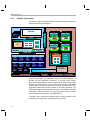
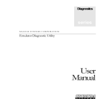
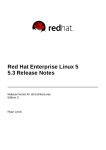
4.1.2
Software Components
The following figure shows the software components used for application
development with the DVEVM kit:
VISA API
Application
I/O
I/O
I/O
DMAI
VISA API
Codec Engine
Operating System
Adaptation Layer
(OSAL)
VID
SPH
IMG
AUD
Engine
Server
xDM
API
User Space
Speech Codec
Linux APIs
CMEM
Driver
USB 2.0
Driver
EMAC
Driver
Video
Driver
Audio
Driver
File
(ATA)
MMC/SD
Driver
SPI
Driver
Link
Driver
UART
Driver
Watchdg
I/O
Timer
I2C
I/O
Driver
DSP/BIOS™ Link
ARM Subsystem
xDM
API
I-Node
Image-Task
Video
Codec
xDM
API
S-Node
Speech-Task
xDM
API
Transport
Imaging
Codec
A-Node
Audio-Task
Speech
Codec
xDM
API
Framework
Components
Kernel Space
GP
I/O
Timer
V-Node
Video-Task
DMAN3 ACPY3
DSKT2 RMAN
Audio
Codec
Codec
Engine
Remote
Server
DSP/BIOS™
DSP Subsystem + Co-Processor
In the previous figure, your application runs on the ARM subsystem. It
handles I/O and application processing. To process video, image,
speech, and audio signals it uses the VISA APIs provided by the Codec
Engine. The Codec Engine, in turn, uses services such as DSP/BIOS
Link and protocols such as xDAIS and xDM to communicate with a preconfigured Codec Engine Remote Server on the DSP subsystem. The
DSP handles signal processing and the results are available to the ARM
subsystem in shared memory. For more information, see the Codec
Engine Application Developer's Guide (SPRUE67).
In addition, Linux running on the ARM makes a large number of APIs
available to your application, including drivers and timers.
4-4
Preparing to Install
4.2
Preparing to Install
On a host system, mount the DVEVM demonstration DVD and copy the
following files to a temporary location with at least 2.3 GB available
space. Since you can delete the installation files after installing the
software, a directory like /tmp is recommended.
❏
mvl_5_0_demo_sys_setuplinux.bin (disk 1)
❏
mvl_5_0_0_demo_lsp_setuplinux_#_#_#_#.bin (disk 2)
❏
dvsdk_setuplinux_#_#_#_#.bin (disk 2)
❏
xdctools_setuplinux_#_#_#.bin (disk 2)
❏
bios_setuplinux_#_#_#_#.bin (disk 2)
❏
TI-C6x-CGT-v#.#.#.#.bin (disk 2)
Updates to these installers may be available on the TI DaVinci Software
Updates website listed in Section 1.4.
Ensure that an X graphical display is available, and point your DISPLAY
environment variable to this value. For example:
csh:
host $ setenv DISPLAY cnabc0314159d1:0
ksh or bash:
host $ export DISPLAY=cnabc0314159d1:0
4.3
Installing the Software
Installing the software used by the DVEVM involves performing the
following steps:
❏
Section 4.3.1, Installing the Target Linux Software
❏
Section 4.3.2, Installing the DVSDK Software
❏
Section 4.3.3, Installing the A/V Demo Files
❏
Section 4.3.4, Installing the SoC Analyzer
❏
Section 4.3.5, Exporting a Shared File System for Target Access
❏
Section 4.3.6, Testing the Shared File System
❏
Section 4.3.7, Configuring the Boot Setup for PAL Video Users
DVEVM Software Setup
4-5
Installing the Software
4.3.1
Installing the Target Linux Software
This section explains how to install Linux for use on the target board. This
is a demonstration version of MontaVista Linux Pro v5.0.
Note that separate versions of Linux are used by the target and your host
Linux workstation. The following Linux host operating system is tested
with the DVEVM: Red Hat Enterprise Linux v4 (Server Edition).
To install the Linux software, follow these steps:
1) Log in as root on your host Linux workstation. This will allow you to
successfully run the graphical installer to install MontaVista Linux.
2) Execute each of the following bin files (where #_#_#_# is the current
version number) from the temporary location that they were copied in
order to extract the installers for the Linux tools, Linux kernel, and the
file system. If a bin file does not run, make sure these files are
executable (use chmod +x *.bin).
Instead of the default installation directory, we suggest that you
change the installation directory to /opt/mv_pro_5.0.
host $ ./mvl_5_0_demo_sys_setuplinux.bin
host $ ./mvl_5_0_0_demo_lsp_setuplinux_#_#_#_#.bin
3) After you execute these .bin files, make sure the following files are
located in /opt/mv_pro_5.0 (or in the /mv_pro_5.0 subdirectory of the
directory you chose in place of the default):
■
mvltools5_0_#######.tar.gz
■
DaVinciLSP_#_#_#_#.tar.gz
4) Go to the location where you will unpack the tar files. For example:
host $ cd /opt/mv_pro_5.0
5) Unpack the tar files (as root) by using the following commands:
host $ tar zxf mvltools5_0_#######.tar.gz
host $ tar zxf DaVinciLSP_#_#_#_#.tar.gz
This creates the MontaVista directory structure under the
/opt/mv_pro_5.0/montavista/ directory.
Note that unpacking these tar files will overwrite any existing files that
were previously installed.
Note: The LSP shipped with the DVSDK is a multi-platform LSP; it
is not configured for a particular platform. As shipped, this LSP
cannot be used to build the demo or example applications. It must
first be copied to a user area and configured/built for the EVM.
Please see Section 4.5 for instructions.
4-6
Installing the Software
4.3.2
Installing the DVSDK Software
The DVSDK software includes Codec Engine components, DSP/BIOS
Link, sample data files, xDAIS and xDM header files, and a contiguous
memory allocator for Linux (CMEM).
Note: The installers for DSP/BIOS and Code Generation Tools
(codegen) have a different default installation location. However,
we strongly recommend that you change the default installation
locations to place the components together (if you have not already
installed the Linux versions of these components elsewhere). This
simplifies the build setup steps.
To install the DVSDK software using the Linux installer, follow these
steps:
1) Log in using a user account. The user account must have execute
permission
for
the
dvsdk_setuplinux_#_#_#_#.bin
and
xdctools_setuplinux_#_#_#.bin files.
2) Execute the DVSDK installer that you previously copied from the
DVSDK DVD. For example:
host $ cd /tmp
host $ ./dvsdk_setuplinux_#_#_#_#.bin
This installs the DVSDK in /home/<useracct>/dvsdk_#_#.
3) Execute the XDC installer that you previously copied from the
DVSDK DVD. For example:
host $ ./xdctools_setuplinux_#_#_#_#.bin
When you are prompted, do not use the default installation location.
Instead, install the software in the directory created in Step 2. For
example, /home/<useracct>/dvsdk_#_#.
4) Execute the DSP/BIOS installer that you previously copied from the
DVSDK DVD. For example:
host $ ./bios_setuplinux_5_#_#_#.bin
When you are prompted, do not use the default installation location.
Instead, install the software in the directory created in Step 2. For
example, /home/<useracct>/dvsdk_#_#.
5) Execute the Code Generation Tools installer that you previously
copied from the DVSDK DVD. For example:
host $ ./TI-C6x-CGT-v#.#.#.#.bin
DVEVM Software Setup
4-7
Installing the Software
When the installer prompts for an installation location, do not use the
default location. Instead, use the entire path to the dvsdk_#_#
codegen directory. You will need to manually create the folder
cg6x_6_#_#, where # represents part of the version number. For
example:
/home/<useracct>/dvsdk_#_#/cg6x_6_0_16.
Remember to set the environment variable as directed by the
installer. For example:
C6X_C_DIR="/home/<useracct>/dvsdk_#_#/cg6x_6_#_#/include:
/home/<useracct>/dvsdk_#_#/cg6x_6_#_#/lib"
6) You can now delete the .bin files that you loaded into the temporary
directory.
Note: You can uninstall these components by using the rm -rf
command on its directory. You should ignore the uninstall files
created by the installer.
4.3.3
Installing the A/V Demo Files
Disk 2 contains the A/V files used by the demos. After following the
instructions in the previous section, follow these instructions to install the
A/V files:
1) Go to the DVSDK directory that you set up previously. For example:
host $ cd /home/<useracct>/dvsdk_#_#
2) Mount disk 2 and copy the data.tar.gz file to your DVEVM directory.
For example:
host $ cp <mount location>/data.tar.gz .
3) Extract the A/V data files. For example:
host $ tar xfz data.tar.gz
4-8
Installing the Software
4.3.4
Installing the SoC Analyzer
SoC Analyzer is a graphical tool that runs on a Windows development
host and uses data collected from Linux, DSP/BIOS, and Codec Engine
to provide system-level execution and performance analysis for
debugging and profiling DVEVM software execution. Follow these
instructions to install SoC Analyzer:
1) Insert the TI DVSDK software disk into the Windows development
host PC.
2) Browse to the SoCAnalyzer/WinXP folder.
3) Double-click on the SoCAnalyzer_#.#.#.#.exe file to start the
installer.
4) Follow the installer’s prompts to install the software.
4.3.5
Exporting a Shared File System for Target Access
Although the board’s hard drive contains a file system, during
development it is more convenient to have the target board NFS mount
a file system on a host Linux workstation. Once you have tested the
application, you can store it on the board’s hard drive for a standalone
demonstration.
Note: Using video files from an NFS file system may result in a low
frame rate when encoding/decoding videos.
Before the board can mount a target file system, you must export that
target file system on the host Linux workstation. The file system uses an
NFS (Network File System) server. The exported file system will contain
the target file system and your executables.
To export the file system from your NFS server, perform the following
steps. You only need to perform these steps once.
1) Log in with a user account on the host Linux workstation.
2) Perform the following commands to prepare a location for the
MontaVista file system. For example:
host $ cd /home/<useracct>
host $ mkdir -p workdir/filesys
host $ cd workdir/filesys
3) Switch user to "root" on the host Linux workstation.
host $ su root
DVEVM Software Setup
4-9
Installing the Software
4) Perform the following commands to create a copy of the target file
system with permissions set for writing to the shared area as
<useracct>. Substitute your user name for <useracct>. If you
installed in a location other than /opt/mv_pro_5.0, use your location
in the cp command.
host $ cp -a /opt/mv_pro_5.0/montavista/pro/devkit/arm/v5t_le/target/* .
host $ chown -R <useracct> opt
5) Edit the /etc/exports file on the host Linux workstation (not the
exports file on the target filesystem). Add the following line for
exporting the filesys area, substituting your user name for
<useracct>. Use the full path from root; ~ may not work for exports
on all file systems.
/home/<useracct>/workdir/filesys *(rw,no_root_squash,no_all_squash,sync)
Note: Make sure you do not add a space between the * and the ( in
the above command.
6) Still as root, use the following commands to make the NFS server
aware of the change to its configuration and to invoke an NFS restart.
host $ /usr/sbin/exportfs -av
host $ /sbin/service nfs restart
Note: Use exportfs
-rav to re-export all directories. Use
/etc/init.d/nfs status to verify that the NFS status is running.
7) Verify that the server firewall is turned off:
host $ /etc/init.d/iptables status
If the firewall is running, disable it:
host $ /etc/init.d/iptables stop
4-10
Installing the Software
4.3.6
Testing the Shared File System
To test your NFS setup, follow these steps:
1) Get the IP address of your host Linux workstations as follows. Look
for the IP address associated with the eth0 Ethernet port.
host $ /sbin/ifconfig
2) Open a terminal emulation window to connect to the EVM board via
RS-232 using the instructions in Section 2.2. If you have a Windows
workstation, you can use HyperTerminal. If you have a Linux
workstation, you might use Minicom. (You may need to turn on line
wrap.)
3) Power on the EVM board, and abort the automatic boot sequence by
pressing a key in the console window (Section 2.2).
4) Set the following environment variables in the console window:
EVM # setenv nfshost <ip address of nfs host>
EVM # setenv rootpath <directory to mount>
EVM # setenv bootargs video=davincifb:vid0=720x576x16,
2500K:vid1=720x576x16,2500K:osd0=720x576x16,2025K
davinci_enc_mngr.ch0_output=COMPOSITE
davinci_enc_mngr.ch0_mode=$(videostd)
console=ttyS0,115200n8 noinitrd rw ip=dhcp
root=/dev/nfs nfsroot=$(nfshost):$(rootpath),nolock
mem=120M
Note that the setenv bootargs command should be typed on a
single line. Also note that you should avoid using the numeric keypad
to enter numbers, as it can sometimes insert extra invisible
characters.
The <directory to mount> must match what you specified in Step
5 of Section 4.3.5. For example, /home/<useracct>/workdir/filesys.
Hints: You may want to use the printenv command to print a list of
your environment variables. You can also save these setenv
commands in a .txt file from which you can paste them in the future.
5) Save the environment so that you don't have to retype these
commands every time you cycle power on the EVM board:
EVM # saveenv
6) Boot the board using NFS:
EVM # boot
7) You can now log in as "root" with no password required.
DVEVM Software Setup
4-11
Installing the Software
See Section A.4, Alternate Boot Methods for information about booting
with TFTP or NFS and using flash or the EVM’s hard drive.
4.3.7
Configuring the Boot Setup for PAL Video Users
You can configure the EVM to select either the NTSC or PAL video
standard during the default boot sequence. To select PAL, set switch 10
on the S3 (USER) user bank of switches to On. For NTSC, set this switch
to Off. The switch causes the U-Boot environment variable "videostd" to
be set to "pal" or "ntsc".
Using the "videostd" variable in the "bootargs" environment variable
passed to the Linux kernel causes the corresponding video standard to
be used by the display (VPBE) driver. For example:
EVM # setenv bootargs video=davincifb:vid0=720x576x16,
2500K:vid1=720x576x16,2500K:osd0=720x576x16,2025K
davinci_enc_mngr.ch0_output=COMPOSITE
console=ttyS0,115200n8 noinitrd rw ip=dhcp
root=/dev/hda1 mem=120M
EVM # setenv bootcmd 'setenv setboot setenv bootargs
\$(bootargs) davinci_enc_mngr.ch0_mode=\$(videostd); run
setboot; bootm 0x2050000'
When the "boot" command is run in U-Boot, the value of "videostd" is
substituted based on the setting of the switch.
See Section A.1, Changing the Video Input/Output Methods for
information about switching to S-Video and Component video.
4.3.8
Notes on Using Evaluation/Production Codecs
As part of the DVSDK installation, you received a number of codecs:
4-12
❏
H.264 Base Profile Decoder
❏
H.264 Base Profile Encoder
❏
MPEG4 Restricted Simple Profile Decoder
❏
MPEG4 Simple Profile Encoder
❏
MPEG2 Decoder
❏
AAC Decoder
❏
MP3 Decoder
❏
G.711 Decoder (not a TI codec)
❏
G.711 Encoder (not a TI codec)
Setting Up the Build/Development Environment
These codecs are provided under a "for demonstration-only" license
agreement. If you wish to use these codecs in a production development
environment, you can go to the DVEVM Updates web site at
http://www.ti.com/dvevmupdates to download the latest production
versions, along with the appropriate license agreement.
4.4
Setting Up the Build/Development Environment
To set up the GPP-side development and build environment, follow these
steps:
1) Log in to your user account (and not as root) on the NFS host
system.
2) Set your PATH so that the MontaVista tool chain host tools and cross
compiler (arm_v5t_le-gcc) can be found. For example, in a default
installation of the MontaVista LSP, you should add a definition like
the following to your shell resource file (for example, ~/.bashrc):
PATH="/opt/mv_pro_5.0/montavista/pro/devkit/arm/v5t_le/bin:
/opt/mv_pro_5.0/montavista/pro/bin:
/opt/mv_pro_5.0/montavista/common/bin:$PATH"
If you installed in a location other than /opt/mv_pro_5.0, use your
own location in the PATH.
3) Remember to use the following command after modifying your
.bashrc file:
host $ source ~/.bashrc
4.4.1
Writing a Simple Program and Running it on the EVM
Make sure you have performed the steps in Section 4.3.5, Exporting a
Shared File System for Target Access and Section 4.4, Setting Up the
Build/Development Environment.
Perform the following steps on the NFS host system as user (not as root):
1) host $ mkdir /home/<useracct>/workdir/filesys/opt/hello
2) host $ cd /home/<useracct>/workdir/filesys/opt/hello
3) Create a file called hello.c with the following contents:
#include <stdio.h>
int main() {
printf("Buongiorno DaVinci!\n");
return 0;
}
DVEVM Software Setup
4-13
Building a New Linux Kernel
4) host $ arm_v5t_le-gcc hello.c -o hello
Perform the following steps on the target board. You may use either the
target's console window (Section 2.2) or a telnet session.
1) target $ cd /opt/hello
2) Run ./hello. The output should be:
Buongiorno DaVinci!
4.5
Building a New Linux Kernel
If you modify the target’s Linux kernel sources, you will need to rebuild it
and then boot it up by either replacing the kernel that comes installed on
the EVM board’s flash or by having the U-Boot utility use TFTP to boot
the kernel over a network connection.
Make sure you have completed Section 4.4, Setting Up the
Build/Development Environment and Section 4.4.1, Writing a Simple
Program and Running it on the EVM before attempting to build a new
kernel.
To rebuild the Linux Kernel, follow these steps:
1) Log in to your user account (not as root).
2) Set the PLATFORM variable in the Rules.make file as described in
Section 4.6.
3) Use commands like the following to make a local working copy of the
MontaVista Linux Support Package (LSP) in your home directory.
This copy contains the embedded Linux 2.6.18 kernel plus the
DaVinci drivers. If you installed in a location other than
/opt/mv_pro_5.0, use your location in the cp command.
host
host
host
host
$
$
$
$
cd /home/<useracct>
mkdir -p workdir/lsp
cd workdir/lsp
cp -R /opt/mv_pro_5.0/montavista/pro/devkit/lsp/ti-davinci .
4) Use the following commands to configure the kernel using the
DaVinci defaults. Note that CROSS_COMPILE specifies a prefix for
the executables that is used during compilation:
host $ cd ti-davinci/linux-2.6.18_pro500
host $ make ARCH=arm CROSS_COMPILE=arm_v5t_le- davinci_dm644x_defconfig
4-14
Building a New Linux Kernel
5) To modify the kernel options, you will need to use a configuration
command such as "make menuconfig" or "make xconfig". To enable
the MontaVista default kernel options, use the following command:
host $ make ARCH=arm CROSS_COMPILE=arm_v5t_le- checksetconfig
6) If you want to enable Linux Trace for the SoC Analyzer, follow these
substeps. Otherwise, skip to Step 7.
a) Use this command to go to the configuration menu for the ARM:
host $ make ARCH=arm CROSS_COMPILE=arm_v5t_le- menuconfig
b) Navigate to Device Drivers->Filesystems->Pseudo Filesystems.
c) Set Relayfs file system support to "built-in".
d) Return to the main menu and navigate to General Setup.
e) Enable Linux Trace Toolkit Support as "built-in".
f)
Select Exit to save your changes and exit the configuration
screen.
7) Compile the kernel using the following command:
host $ make ARCH=arm CROSS_COMPILE=arm_v5t_le- uImage
8) If the kernel is configured with any loadable modules (that is,
selecting <M> for a module in menuconfig), use the following
commands to rebuild and install these modules:
host $ make ARCH=arm CROSS_COMPILE=arm_v5t_le- modules
host $ make ARCH=arm CROSS_COMPILE=arm_v5t_leINSTALL_MOD_PATH=/home/<useracct>/workdir/filesys
modules_install
9) Use the following command to copy the uImage to a place where UBoot can use TFTP to download it to the EVM. These commands
assume you are using the default TFTP boot area, which is /tftpboot.
If you use another TFTP root location, please change /tftpboot to
your own TFTP root location. (Perform these commands as root or
use a chown uImage command to get ownership of the file.)
host $ cp /home/<useracct>/workdir/lsp/ti-davinci/linux-2.6.18_pro500/arch/ arm/boot/uImage
/tftpboot
host $ chmod a+r /tftpboot/uImage
For more information on setting up a TFTP server, see Section A.3.
See a standard Linux kernel reference book or online source for more
about Linux build configuration options.
DVEVM Software Setup
4-15
Rebuilding the DVEVM Software for the Target
4.6
Rebuilding the DVEVM Software for the Target
To place demo files in the /opt/dvsdk/dm6446 directory, you need to
rebuild the DVSDK software. To do this, follow these steps:
1) If you have not already done so, rebuild the Linux kernel as described
in Section 4.5.
2) Change directory to dvsdk_#_#.
3) Edit the Rules.make file in the dvsdk_#_#. directory.
■
Set PLATFORM to match your EVM board as follows:
■
Set DVSDK_INSTALL_DIR to the top-level DVSDK installation
directory as follows:
PLATFORM=dm6446
DVSDK_INSTALL_DIR=/home/<useracct>/dvsdk_#_#
■
Make sure EXEC_DIR points to the opt directory on the NFS
exported file system as follows:
EXEC_DIR=/home/<useracct>/workdir/filesys/opt/dvsdk/$(PLATFORM)
■
Make sure MVTOOL_DIR points to the MontaVista Linux tools
directory as follows:
MVTOOL_DIR=/opt/mv_pro_5.0/montavista/pro/devkit/arm/v5t_le
■
Make sure LINUXKERNEL_INSTALL_DIR is defined as follows:
LINUXKERNEL_INSTALL_DIR=/home/<useracct>/workdir/lsp/ti-davinci/linux-2.6.18_pro500
■
Modify the following environment variables as needed to match
the locations of these components on your Linux host. We
recommend that these components be installed in the
/home/<useracct>/dvsdk_#_# directory, but you may have
installed them elsewhere.
BIOS_INSTALL_DIR=/home/<useracct>/dvsdk_#_#/bios_#_#
FC_INSTALL_DIR=/home/<useracct>/dvsdk_#_#/fc_#_#
XDC_INSTALL_DIR=/home/<useracct>/dvsdk_#_#/xdctools_#_#
4) While in the same directory that contains Rules.make, use the
following commands to build the DVSDK demo applications and put
the resulting binaries on the target file system specified by
EXEC_DIR.
host $ make clean
host $ make
host $ make install
4-16
Booting the New Linux Kernel
5) You can test the rebuilt DVEVM software by booting your NFS file
system and running the demos from the command line as described
in Section 3.4.
4.7
Booting the New Linux Kernel
After building the new kernel, in order to use it to boot the DaVinci board,
you must transfer it to the board via TFTP. It is assumed you have
completed the steps in Section 4.5, Building a New Linux Kernel and the
boot file, uImage has been copied to /tftpboot (or some other site-specific
TFTP accessible location).
1) Power on the EVM board, and abort the automatic boot sequence by
pressing a key in the console window (Section 2.2).
2) Set the following environment variables. (This assumes you are
starting from a default, clean U-Boot environment. See Section 3.1,
Default Boot Configuration for information on the U-Boot default
environment.)
EVM # setenv bootcmd 'dhcp;bootm'
EVM # setenv serverip <tftp server ip address>
EVM # setenv bootfile uImage
EVM # setenv bootargs video=davincifb:vid0=720x576x16,
2500K:vid1=720x576x16,2500K:osd0=720x576x16,2025K
davinci_enc_mngr.ch0_output=COMPOSITE
davinci_enc_mngr.ch0_mode=$(videostd)
console=ttyS0,115200n8 noinitrd rw ip=dhcp
root=/dev/hda1 mem=120M
Note that the setenv bootargs command should be typed on a
single line.
3) Boot the board:
EVM # boot
This configuration boots a new Linux kernel via TFTP with a hard drive
based file system. To boot via TFTP using an NFS file system, see
Section A.4.4.
For instructions on how to verify that your host workstation is running a
TFTP server, and for instructions on what to do if it isn’t, see Section A.3.
For more details on booting, see Section A.4.
DVEVM Software Setup
4-17
Testing the Build Environment
4.8
Testing the Build Environment
To test your DVSDK software installation, you can build one of the Codec
Engine servers. This server is a DSP-side application. Building it tests the
installation of DSP-side development components.
To build the video_copy server, follow these steps:
1) Go to /home/<useracct>/dvsdk_#_#/codec_engine_#_#/examples
and open the build_instructions.html file.
2) Follow the step-by-step instructions for building examples. When you
are editing the xdcpaths.mak file, note that the DVSDK installation
does not include the cetools directory, so you will need to set the
USE_CETOOLS_IF_EXISTS variable to 0, and modify additional
variables to point to the locations of xDAIS, DSP/BIOS Link, CMEM,
and Framework Components.
3) Go
to
the
video_copy
server
directory.
(/home/<useracct>/dvsdk_#_#/codec_engine_#_#/examples/
servers/video_copy) to inspect the built server.
4.9
Using the Digital Video Test Bench (DVTB)
The Digital Video Test Bench (DVTB) is a Linux utility that was developed
to execute end-to-end data flows using the DVSDK for any platform.
DVTB uses the Codec Engine VISA APIs and Linux driver peripheral
APIs to encode and decode video, image, audio and speech streams.
Using DVTB, you can configure codecs and/or peripherals before starting
a data flow. This enables you to try different use case scenarios and
evaluate the system.
The
DVSDK
installation
places
DVTB
in
the
/home/<useracct>/dvsdk_#_#/dvtb_#_#_# directory, where #_#_# is the
DVTB version number).
To install DVTB to the target file system, perform the following steps on
the host machine where the DVSDK has been installed:
1) Make sure the Rules.make file defines PLATFORM correctly as
described in Section 4.6.
2) Perform the following commands:
host $ cd /home/<useracct>/dvsdk_#_#/dvtb_#_#_#
host $ make clean CONFIGPKG=dm6446
host $ make CONFIGPKG=dm6446
4-18
Using the Digital Video Test Bench (DVTB)
3) Copy the binaries "dvtb-d" and "dvtb-r" to /opt/dvsdk/dm6446 on the
device’s target filesystem and run it there. It must be in the same
directory as the DSP executables.
For further details on the DVTB, see the following documents:
❏
Release Notes.
/home/<useracct>/dvsdk_#_#/dvtb_#_#_#/docs/dvtb_release_notes.pdf
❏
User Guide..
/home/<useracct>/dvsdk_#_#/dvtb_#_#_#/docs/dvtb_user_guide.pdf
DVEVM Software Setup
4-19
Running The SoC Analyzer
4.10
Running The SoC Analyzer
Built upon Texas Instruments' eXpressDSP data visualization technology
(DVT), the SoC Analyzer simplifies debugging, analysis, and optimization
of DVEVM applications. It collects execution, interaction, and resource
utilization logs from Linux, DSP/BIOS, Codec Engine, and drivers and
presents system-level analysis and graphical visualization such as:
❏
System execution flow
❏
System performance
❏
Resource utilization
❏
Processor interaction
Install the SoC Analyzer as described in Section 4.3.4.
4-20
Documentation for DSP-Side Development
To run the SoC Analyzer, double-click the SoC Analyzer icon on the
Windows Desktop or select it from the Windows Start menu under Texas
Instruments.
The SoC Analyzer comes with online help, which can be accessed from
the SoC Analyzer Help menu (choose Help->Help Contents). Select the
DM644x SoC Analyzer User Guide.
Follow the "Getting Started" chapter of the DM644x SoC Analyzer User
Guide, which includes steps on how to run the tool with demonstration
logs shipped with the product. This "Getting Started" chapter also
contains the steps you should perform to enable your applications to
collect logs for the SoC Analyzer. The DVEVM Demo Application has
such logging enabled by default. The uImage must be rebuilt to enable
logging.
4.11
Documentation for DSP-Side Development
After you have installed the DVSDK software, you can begin to create
and modify DSP-side applications for your DM644x.
The following table lists places to look for documentation on using each
component of the DVSDK. Documents in PDF, HTML, and text format
are included in the installations with each product.
Table 4-1.
Documentation for DVSDK Components
Component
Title
DSP/BIOS
TMS320C6000 DSP/BIOS /home/<useracct>/dvsdk_#_#/bios_5_#/packages/ti/bios/doc
API Reference (SPRU403)
Application Notes
Code
Generation
Tools
Location
www.dspvillage.com
TMS320C6000 Optimizing www.dspvillage.com
C Compiler User's Guide
(SPRU187)
TMS320C6000 Programmer's Guide (SPRU189)
www.dspvillage.com
Framework
Components
Release Notes
/home/<useracct>/dvsdk_#_#/framework_components_#_#
Digital Video
Test Bench
README.txt
/home/<useracct>/dvsdk_#_#/dvtb/docs
DVEVM Software Setup
4-21
Documentation for DSP-Side Development
Table 4-1.
Component
Documentation for DVSDK Components
Title
Location
Section 4.9, Using the Digi- this document
tal Video Test Bench
(DVTB)
Codec Engine Codec Engine Application /home/<useracct>/dvsdk_#_#/codec_engine_#_#/docs
Developer User's Guide
(SPRUE67)
Codec Engine Server
Integrator User's Guide
(SPRUED5)
/home/<useracct>/dvsdk_#_#/codec_engine_#_#/docs
Codec Engine Algorithm
Creator User's Guide
(SPRUED6)
/home/<useracct>/dvsdk_#_#/codec_engine_#_#/docs
Example Build and Run
Instructions
/home/<useracct>/dvsdk_#_#/codec_engine_#_#/examples/
Codec Engine API
Reference
/home/<useracct>/dvsdk_#_#/codec_engine_#_#/docs/html/
Codec Engine SPI
Reference Guide
/home/<useracct>/dvsdk_#_#/codec_engine_#_#/docs/spi/html/
Configuration Reference
/home/<useracct>/dvsdk_#_#/codec_engine_#_#/xdoc/
build_instructions.html
index.html
index.html
index.html
XDC Tools
Documentation Links
(used by
Codec Engine)
xDAIS
4-22
xDAIS-DM (Digital
Media) User Guide
(SPRUEC8)
/home/<useracct>/dvsdk_#_#/xdctools_#_#/docs/index.html
/home/<useracct>/dvsdk_#_#/xdais_5_00/packages/ti/xdais/dm/docs
Appendix A
Additional Procedures
This appendix describes optional procedures you may use depending on
your setup and specific needs.
Topic
Page
A.1 Changing the Video Input/Output Methods. . . . . . . . . . . . . . . . . . . . A–2
A.2 Putting Demo Applications in the Third-Party Menu . . . . . . . . . . . . A–5
A.3 Setting Up a TFTP Server . . . . . . . . . . . . . . . . . . . . . . . . . . . . . . . . . . A–7
A.4 Alternate Boot Methods . . . . . . . . . . . . . . . . . . . . . . . . . . . . . . . . . . . A–8
A.5 Rebuilding DSP/BIOS Link . . . . . . . . . . . . . . . . . . . . . . . . . . . . . . . . A–11
A.6 Restoring and Updating the EVM Hard Disk Drive . . . . . . . . . . . . . A–12
A-1
Changing the Video Input/Output Methods
A.1
Changing the Video Input/Output Methods
The EVM can input video using the following methods:
❏
Composite [default]
❏
S-Video (best quality)
In addition, there are three types of video output:
❏
Composite [default] (lowest quality)
❏
S-Video (medium quality)
❏
Component (best quality)
There is a significant quality difference between the different inputs and
outputs. However, the cables in the DVEVM kit support only composite
video. You will need to get S-Video or Component video cables from
another source.
A.1.1
Using S-Video Input
To switch to higher-quality S-Video input, follow these steps:
1) Connect your S-Video connector to the S-Video input port, which is
directly to the left of the currently-used composite video input port.
2) Select S-Video input on the command line when you execute the
encode or encodedecode demo using the '-x' flag.
S-Video
IN
A-2
Changing the Video Input/Output Methods
A.1.2
Using S-Video Output
To switch to higher-quality S-Video output, follow these steps:
1) Unplug the composite video connector. Then, connect your S-Video
connector to the S-Video output port, which is to the right of the
currently-used composite video output port.
S-Video
OUT
The DVEVM kit does not include an S-Video cable. In addition, you
will need a video display with an S-Video input.
2) On the kernel command line, you can configure the EVM to select
both NTSC vs. PAL and the S-Video output format (see Section
4.3.7, Configuring the Boot Setup for PAL Video Users). For
example, if you want both NTSC and S-Video output, use the
following:
davinci_enc_mngr.ch0_output=SVIDEO davinci_enc_mngr.ch0_mode=NTSC
If you want both PAL and S-Video, use the following:
davinci_enc_mngr.ch0_output=SVIDEO davinci_enc_mngr.ch0_mode=PAL
Additional Procedures
A-3
Changing the Video Input/Output Methods
A.1.3
Using Component Video Output
To switch to highest-quality component video output, follow these steps:
1) Connect your component video connectors to the connectors in a
square on the far left of the board. Instead of connecting one
connector as with composite video, connect the YPrPb connectors
as shown here.
Pr
Pb
Y
The DVEVM kit does not include a 3-connector cable used for
component (YPrPb) video. The cable you use may have red, green,
and blue connectors, but you should be aware that the Y, Pr, and Pb
signals used by component video do not correspond to RGB signals.
In addition, you will need a video display with component video
inputs.
2) On the kernel command line, you can configure the EVM to select
both NTSC vs. PAL and the component video output format (see
Section 4.3.7, Configuring the Boot Setup for PAL Video Users). For
example, if you want both NTSC and component video output, use
the following:
davinci_enc_mngr.ch0_output=COMPONENT davinci_enc_mngr.ch0_mode=NTSC
If you want both PAL and component video, use the following:
davinci_enc_mngr.ch0_output=COMPONENT davinci_enc_mngr.ch0_mode=PAL
A-4
Putting Demo Applications in the Third-Party Menu
A.2
Putting Demo Applications in the Third-Party Menu
You can add your own demos to the Third-Party Menu by following the
steps in this section. Only four demos can be shown at once in the userinterface. If you add more than four demos, the first four in alphabetical
order are shown.
1) Create the following files for your demo:
■
logo.jpg. This is the logo of the third party company which will be
showed next to the demo description. The picture needs to be in
JPEG format and of size 50x50.
■
readme.txt. This is a text file. The first 40 characters of the file
should briefly describe the demo. The demo interface displays
up to 40 characters, but stops if it encounters a new line
character. For example, the file might contain "Video Phone
demo" or "Network Audio demo".
■
app.sh. This is an executable that launches your demo. It can
either be the demo executable itself or a shell script that
executes the executable. (If this is a shell script, make sure its
executable bit is set for all). A script could look something like:
#!/bin/sh
exec ./mydemoname
■
other files. If app.sh is a shell script, your demo executable will
have some other name. You may also need to include data files
or other files used by the executable.
Note: The demo application must use relative paths to access any
files it needs at runtime. This because the archive is extracted to
another location from which the demo is executed.
2) Create a gzipped tar file (ends with .tar.gz) that archives all the files
in the previous list. For example, if your files are logo.jpg, readme.txt,
and app.sh, you could use the following command:
tar cvzf ti_videophone.tar.gz logo.jpg readme.txt app.sh
Name the tar file using <company>_<demoname>.tar.gz (with no
spaces in the file name) as the convention. For example, a video
phone demo created by Texas Instruments would be named
ti_videophone.tar.gz. The name must be unique since all demos are
installed in the same directory.
The three required files must be in the top-level directory of the
archive. Other files may be in subdirectories, so long as the demo
Additional Procedures
A-5
Putting Demo Applications in the Third-Party Menu
uses relative references to access them. For example, the following
directory structure might be used in the archive:
|-|-|
|
|-`--
app.sh
data
|-- datafile1
`-- datafile2
logo.jpg
readme.txt
To check the format of the file you create, execute the following
command in Linux. The result should say "gzip compressed data".
file <filename>.tar.gz
3) Put your archive in the "thirdpartydemos" subdirectory of the target
installation directory. This is where the DVSDK software was
installed on the target file system. The default target installation
directory is /opt/dvsdk/dm6446, so the default location for demo
archives is /opt/dvsdk/dm6446/thirdpartydemos. Do not extract the
contents of the archive in this location. Extraction is performed
behind-the-scenes each time the demo is run.
A-6
Setting Up a TFTP Server
A.3
Setting Up a TFTP Server
You can check to see if a TFTP server is set up with the following
command:
host $ rpm -q tftp-server
If it is not set up, you can follow these steps:
1) If you have not yet installed MontaVista Linux Demo Edition (see
Section 4.3.1), you can download a TFTP server for your Linux host
from many locations on the Internet. Search for "tftp-server".
2) To install TFTP, use this command, where -#.#-# is the version
number portion of the filename:
host $ rpm -ivh tftp-server-#.#-#.rpm
You should see the following output:
warning: tftp-server-#.#-#.rpm:
V3 DSA signature: NOKEY, key ID 4f2a6fd2
Preparing... #################################### [100%]
1:tftp-server ################################### [100%]
3) Confirm that TFTP is installed with this command:
host $ /sbin/chkconfig --list | grep tftp
If you want to turn on the TFTP server, use this command:
/sbin/chkconfig tftp on
The default root location for servicing TFTP files is /tftpboot.
Additional Procedures
A-7
Alternate Boot Methods
A.4
Alternate Boot Methods
The default configuration for the EVM is to boot from flash with the file
system on the EVM’s hard drive. The following are alternate ways you
may want to boot the board:
❏
TFTP boot with hard drive file system (Section A.4.2)
❏
Flash boot with NFS file system (Section A.4.3)
❏
TFTP boot with NFS file system (Section A.4.4)
Section 4.3.7 discusses booting in PAL mode vs. NTSC mode.
The subsections that follow show the environment variable settings used
to enable each boot method.
Note: Using video files from an NFS file system may result in a low
frame rate when encoding/decoding videos.
To boot in one of these modes, follow these steps:
1) Power on the EVM board, and abort the automatic boot sequence by
pressing a key in the console window (Section 2.2).
2) Set the environment variables indicated in the following subsections
for the boot mode you want to use. (Note that the setenv bootargs
command should be typed on a single line.)
3) If you want to use these settings as the default in the future, save the
environment:
EVM # saveenv
4) Boot the board using the settings you have made:
EVM # boot
A.4.1
Booting from Flash Using the EVM’s Hard Drive File System
This is the default, out-of-the-box boot configuration.
A-8
Alternate Boot Methods
To boot in this mode, set the following parameters after you abort the
automatic boot sequence:
EVM # setenv bootcmd bootm 0x2050000
setenv bootcmd nboot 80700000 0 a0000;bootm
EVM # setenv bootargs video=davincifb:vid0=720x576x16,
2500K:vid1=720x576x16,2500K:osd0=720x576x16,2025K
davinci_enc_mngr.ch0_output=COMPOSITE
davinci_enc_mngr.ch0_mode=$(videostd)
console=ttyS0,115200n8 noinitrd rw ip=dhcp
root=/dev/hda1 mem=120M
Note: If you have flashed a new kernel to the NOR flash at an address
other than 0x2050000, modify the bootcmd definition accordingly.
When you boot, look for the following line that confirms the boot mode:
## Booting image at 02050000 ...
A.4.2
Booting via TFTP Using the EVM’s Hard Drive File System
To boot in this mode, set the following parameters after you abort the
automatic boot sequence:
EVM # setenv bootcmd 'dhcp;bootm'
EVM # setenv bootargs video=davincifb:vid0=720x576x16,
2500K:vid1=720x576x16,2500K:osd0=720x576x16,2025K
davinci_enc_mngr.ch0_output=COMPOSITE
davinci_enc_mngr.ch0_mode=$(videostd)
console=ttyS0,115200n8 noinitrd rw ip=dhcp
root=/dev/hda1 mem=120M
EVM # setenv serverip <tftp server ip address>
EVM # setenv bootfile <path on tftpserver>/uImage
When you boot, look for the following lines that confirm the boot mode:
TFTP from server 192.168.160.71; our IP address is
192.168.161.186
Filename 'library/davinci/0.4.2/uImage'.
...
## Booting image at 80700000 ...
Additional Procedures
A-9
Alternate Boot Methods
A.4.3
Booting from Flash Using NFS File System
To boot in this mode, set the following parameters after you abort the
automatic boot sequence:
EVM # setenv bootcmd 0x2050000
setenv bootcmd nboot 80700000 0 a0000;bootmEVM # setenv nfshost <ip address of nfs host>
EVM # setenv rootpath <directory to mount*>
EVM # setenv bootargs video=davincifb:vid0=720x576x16,
2500K:vid1=720x576x16,2500K:osd0=720x576x16,2025K
davinci_enc_mngr.ch0_output=COMPOSITE
davinci_enc_mngr.ch0_mode=$(videostd)
console=ttyS0,115200n8 noinitrd rw ip=dhcp root=/dev/nfs
nfsroot=$(nfshost):$(rootpath),nolock mem=120M
*For example, <directory to mount> might be
/home/<useracct>/workdir/filesys.
Note: If you have flashed a new kernel to the NOR flash at an address
other than 0x2050000, modify the bootcmd definition accordingly.
When you boot, look for the following lines that confirm the boot mode:
## Booting image at 02050000 ...
...
Starting kernel ...
...
VFS: Mounted root (nfs filesystem).
A.4.4
Booting via TFTP Using NFS File System
To boot in this mode, set the following parameters after you abort the
automatic boot sequence:
EVM
EVM
EVM
EVM
EVM
EVM
# setenv bootcmd 'dhcp;bootm'
# setenv serverip <tftp server ip address>
# setenv bootfile <name of kernel image>
# setenv rootpath <root directory to mount>
# setenv nfshost <ip address of nfs host>
# setenv bootargs video=davincifb:vid0=720x576x16,
2500K:vid1=720x576x16,2500K:osd0=720x576x16,2025K
davinci_enc_mngr.ch0_output=COMPOSITE
davinci_enc_mngr.ch0_mode=$(videostd)
console=ttyS0,115200n8 noinitrd rw ip=dhcp root=/dev/nfs
nfsroot=$(nfshost):$(rootpath),nolock mem=120M
A-10
Rebuilding DSP/BIOS Link
The <root directory to mount> must match the file system that you set up
on your workstation. For example, /home/<useracct>/workdir/filesys.
When you boot, look for the following lines that confirm the boot mode:
TFTP from server 192.168.160.71; our IP address is
192.168.161.186
Filename 'library/davinci/0.4.2/uImage'.
...
Starting kernel ...
...
VFS: Mounted root (nfs filesystem).
A.5
Rebuilding DSP/BIOS Link
If you want to rebuild the DSP/BIOS Link package, follow these steps
(assuming you are using the bash shell):
1) Edit the davinci_mvlpro5.0.mk file, which is in the
/home/<useracct>/dvsdk_#_#/dsplink_#/packages/dsplink/make/Linux/
directory, to make sure the BASE_BUILDOS and BASE_CGTOOLS
variables correctly point to the correct locations. For example:
BASE_BUILDOS := /home/<useracct>/workdir/lsp/ti-davinci/linux-2.6.18_pro500
BASE_CGTOOLS := /opt/mv_pro_5.0/montavista/pro/devkit/arm/v5t_le/bin
2) Define the DSPLINK environment variable to be the absolute path to
the "dsplink" directory. (Use export for bash shell, and setenv for tcsh
shell.) For example:
host $ export DSPLINK=/home/<useracct>/dvsdk_#_#/dsplink_#/packages/dsplink
3)
Move to the Linux build script directory:
host $ cd $DSPLINK/etc/host/scripts/Linux
4) Build DSP/BIOS Link as follows:
host $ sh –f buildmodule.sh
5) The rebuilt kernel module is called dsplinkk.ko. It is located in the
$DSPLINK/gpp/export/BIN/Linux/Davinci/DM6446/RELEASE/
directory.
Additional Procedures
A-11
Restoring and Updating the EVM Hard Disk Drive
A.6
Restoring and Updating the EVM Hard Disk Drive
This section describes how to restore and update all the files on the EVM
hard disk drive (HDD), including the Linux file system and the demos.
Using these restore procedures, you can return your board to a known
state if anything happens to the data on the EVM board’s HDD.
This section assumes that you have configured a host Linux workstation
with the software necessary to perform an NFS root mount with the EVM
as described in Section 4.3.5 and Section 4.3.6.
For further information about upgrading and flashing, see the TI DaVinci
Technology Developers Wiki at http://wiki.davincidsp.com.
In this section, U-Boot is always located at the start of flash memory
(address 0x02000000) on the target. Similarly, uImage, the Linux kernel
program, is booted from the target flash memory address of 0x02050000.
Note: If you have flashed a new kernel to the NOR flash at an address
other than 0x2050000, then the flash memory address will be different.
A.6.1
System Setup
You should make sure the following system setup steps have been
performed before you attempt to restore or update the hard disk drive:
1) Inspect jumper J4, which is labeled "CS2 SELECT". Make sure
FLASH is selected.
2) Connect the Ethernet port of the host workstation to a router.
Configure the host Ethernet port to obtain IP address dynamically via
a DHCP server running inside the router.
3) Connect the Ethernet port of the target EVM to another port on the
same router. This establishes a network connection with your host
workstation.
4) Connect an RS-232 cable from the UART0 port of the target EVM
board to the host workstation.
5) On the host workstation, open a terminal session to the target EVM
board with the following characteristics:
A-12
■
Bits per Second: 115200
■
Data Bits: 8
■
Parity: None
■
Stop Bits: 1
■
Flow Control: None
Restoring and Updating the EVM Hard Disk Drive
For example, you can create a terminal session with HyperTerminal
or TeraTerm on MS Windows, and Minicom or C-Kermit on Linux.
6) Start an NFS server on the host workstation. This document
assumes the host path /home/user/workdir/filesys contains a file
system that the target EVM can use for root mounting.
A.6.2
Configure EVM for NFS Root Mount
Follow these steps to configure your EVM for an NFS root mount:
1) Configure the Boot Switches (S3) to 1011111110. This is the bank of
switches in the middle of the EVM.
2) Power on the EVM and hit any key to enter U-Boot.
3) Configure bootcmd as follows to boot the Linux kernel via flash.
EVM # setenv bootcmd bootm 0x2050000
Note: If you have flashed a new kernel to the NOR flash at an
address other than 0x2050000, modify this command accordingly.
4) Configure bootargs as follows to root mount the file system from
NFS:
EVM # setenv rootpath <root directory to mount>
EVM # setenv nfshost <ip address of nfs host>
EVM # setenv bootargs video=davincifb:vid0=720x576x16,
2500K:vid1=720x576x16,2500K:osd0=720x576x16,2025K
davinci_enc_mngr.ch0_output=COMPOSITE
davinci_enc_mngr.ch0_mode=$(videostd)
console=ttyS0,115200n8 noinitrd rw ip=dhcp root=/dev/nfs
nfsroot=$(nfshost):$(rootpath),nolock mem=120M
The nfsroot option in this command uses the host workstation IP
address. Make sure to replace the <host ip addr> with the actual
address of your host Linux workstation.
5) Optional: Print the U-Boot parameters
EVM # printenv
6) Save the U-Boot parameters
EVM # saveenv
7) Boot EVM from NFS on the host Linux workstation
EVM # boot
8) Log into MontaVista Linux as "root".
Additional Procedures
A-13
Restoring and Updating the EVM Hard Disk Drive
A.6.3
Restore the EVM Hard Disk Drive
The EVM hard disk drive (HDD) can be restored from a target EVM HDD
partition or from the host Linux workstation file system. Either method will
achieve the same result.
Restoring the EVM HDD takes 10 to 15 minutes. The restore script must
uncompress 600 MB of compressed data and load it to the /dev/hda1
partition.
After the hard drive restore process has completed, make sure to restart
the EVM and configure U-Boot to root mount via the local HDD. The steps
for this type of boot are provided in Section A.4.1, Booting from Flash
Using the EVM’s Hard Drive File System.
A.6.4
Restoring From Target EVM HDD Partition
Follow these steps to restore the HDD from the restore partition on the
HDD itself:
1) Make a directory for mounting the HDD restore partition:
EVM # mkdir /mnt/restore
2) Mount the HDD restore partition:
EVM # mount -t ext3 /dev/hda2 /mnt/restore
3) Set the Linux date variable to today's date. If the date is too far off,
the target file system installation generates a bunch of warnings.
EVM # date MMDDHHMMCCYY
For example, for 9:00 am on April 18th, 2006, enter 041809002006.
4) Change directory to /mnt/restore:
EVM # cd /mnt/restore
5) Add execute permissions for the script:
EVM # chmod +x restore-hdd
6) Run the restore script:
EVM # ./restore-hdd
A-14
Restoring and Updating the EVM Hard Disk Drive
7) The script will ask for confirmation: "This will destroy all data on
/dev/hda1 - are you sure?" Type yes.
8) After the HDD restore is complete, shutdown the EVM:
EVM # halt
9) When the "Power down" message is printed in the terminal window,
it is safe to power down the EVM.
10) Restart the EVM and configure U-Boot to root mount via the local
HDD. Follow the steps in Section A.4.1, Booting from Flash Using the
EVM’s Hard Drive File System.
A.6.5
Restoring From Host Linux Workstation File System
This section assumes that you have installed the DVEVM software to the
host Linux /workdir/filesys/restore directory. After an NFS mount, this is
equivalent to /restore for the target EVM.
Follow these steps to restore the HDD from the host Linux workstation
restore directory:
1) On your host workstation, copy the restore directory from the TI
DVSDK disk to /home/<useracct>/workdir/filesys/restore. After NFS
mounting this file system, this will appear as the /restore directory on
the EVM.
2) Login to the EVM as root.
Additional Procedures
A-15
Restoring and Updating the EVM Hard Disk Drive
3) Go to the /restore directory.
EVM # cd /restore
4) Set the Linux date variable to today's date. If the date is too far off,
the target file system installation generates warnings for each file it
installs.
EVM # date MMDDHHMMCCYY
For example, for 9:00 am on April 18th, 2006, enter 041809002006.
5) Add execute permissions on the prep-hdd script.
EVM # chmod +x prep-hdd
6) Run the prep-hdd script in the /restore directory.
EVM # ./prep-hdd /restore
7) The script will ask for confirmation: "Are you sure you want to
partition and format /dev/hda1?" Type yes.
8) After the HDD restore is complete, shutdown the EVM:
EVM # halt
9) When the "Power down" message is printed in the terminal window,
it is safe to power down the EVM.
10) Restart the EVM and configure U-Boot to root mount via the local
HDD. Follow the steps in Section A.4.1, Booting from Flash Using the
EVM’s Hard Drive File System.
If you instead manually restore the overlay.tar.gz file from disk 1 on an
NFS file system, the demos will likely produce a cryptic error. Although
such manual restores are not documented or recommended, you can
correct the problem by turning off the s-bit as follows:
EVM # cd /opt/dvsdk/dm6446
EVM # chmod u-s ${install}/encode ${install}/decode ${install}/encodedecode \
${install}/interface
A-16
This is a draft version printed from file: davinci_gsgIX.fm on 12/18/08
Index
A
console window 2-6
contents of kit 1-3
CPU load 3-5
A/V files 4-8
AAC audio 3-9
application 4-4
ARM9 1-3
arrow buttons 3-4
audio cables 2-3
D
B
battery 1-4, 3-3
bin files 4-6
BIOS_INSTALL_DIR environment variable
block diagram 1-4
boot configurations A-8
flash with hard drive A-8
flash with NFS A-10
NFS 4-11
standard 3-2
TFTP with hard drive A-9
TFTP with NFS A-10
boot sequence A-8
build environment 4-13
C
C64+ DSP 1-3
cables 1-3
connecting 2-2
camera 1-3, 2-3
clock battery 1-4
Code Search button 3-3
Codec Engine 3-5, 3-6, 4-4
documentation 4-22
Codegen Tools
documentation 4-21
installation location 4-7
COM port 2-6
command line demos 3-9
command prompts 4-3
component video A-2, A-4
composite video A-2
4-16
data files 4-8
DaVinci technology 1-2
Decode demo 3-4, 3-8
command line 3-10
demos 3-2
command line 3-9
digital camera 1-3
Digital Video Test Bench (DVTB)
building 4-18, 4-21
documentation 4-18, 4-21
directories
installation 4-8
disks
file contents 4-2
mounting 4-5
display 1-3, 2-2
DISPLAY environment variable 4-5
DSP 4-4
DSP/BIOS
documentation 4-21
installation location 4-7
DSP/BIOS Link 4-4
DVD button 3-3
DVEVM 1-2
installing software 4-7
DVEVM software
rebuilding 4-16
DVSPB 4-3
E
electrostatic precautions 2-2
Encode + Decode demo 3-4, 3-6
command line 3-10
Encode demo 3-4, 3-7
command line 3-10
environment variables
Index--1
Index
K
BIOS_INSTALL_DIR 4-16
FC_INSTALL_DIR 4-16
XDC_INSTALL_DIR 4-16
ESD precautions 2-3
Ethernet 2-4
setup 2-5
EVM # prompt 2-6, 4-3
examples 3-2
exit demo 3-5
exports file 4-10
kit contents
L
F
FC_INSTALL_DIR environment variable
file extensions 3-7, 3-9
file system 4-9
video performance 4-9
files
Decode demo 3-8
Encode demo 3-7
on disks 4-2
flash memory
boot configuration A-8, A-10
G
G.711 speech
3-7, 3-9
H
H.264 video 3-6, 3-7, 3-9
hard disk drive A-12
hard drive 1-3
boot configuration A-8, A-9
HDD A-12
restore A-12, A-14
host $ prompt 4-3
I
Info/Select button 3-5
installation location 4-8
installing
DVEVM software 4-7
hardware 2-2
Linux software 4-6
IR remote 1-3, 2-5, 3-3
resetting code 3-3
1-3
4-16
LCD display 1-3, 2-2
Link, DSP/BIOS 4-4
Linux 4-4
installing 4-6
kernel 4-14
versions supported 4-6
Linux Support Package 4-14
M
microphone 1-3, 2-4
monitor 2-2
MontaVista Linux
demo version 4-3
full version 4-3
MPEG2 video 3-9
MPEG4 video 3-7, 3-9
multimedia peripherals 1-4
N
NFS server 4-9
boot configuration A-10
testing 4-11
video performance 4-9
NTSC video 2-2, 4-12
O
OSD show and hide 3-5
OSD toggle 3-5
overlay.tar.gz file A-16
P
PAL video 2-2, 4-12
PATH environment variable
Pause button 3-5
performance 4-9
peripherals 1-4, 2-2
Play button 3-5
ports 2-4
power 2-5
Power button 3-5
power cable 2-4, 2-5
4-13
Index--2
Index
T
prompts 4-3
Q
quit demo
3-5
R
rebuilding
DVEVM software 4-16
Linux kernel 4-14
Record button 3-5
Red Hat Enterprise Linux 4-6
remote control 1-3, 3-3
resetting code 3-3
restore HDD A-12
Rules.make file 4-16
running applications 3-4
target $ prompt 4-3
terminal session 2-6
test program 4-13
TFTP
boot configuration A-9, A-10
server A-7
transfer files to board 4-17
Third-Party Menu 3-4, A-5
TMS320DM6446 1-3
transparency of OSD 3-5
U
U-Boot utility 4-14
uImage boot file 4-17
V
S
s-bit A-16
serial cable 2-6
serial connection 2-5
SoC Analyzer 4-2, 4-9
software 4-2
components 1-3, 4-4
installing 4-6
Spectrum Digital website
standalone demos 3-2
static precautions 2-2
Stop button 3-5
S-Video A-2
input A-2
output A-3
video cable 2-2
video camera 1-3, 2-3
power 2-3
video formats A-2
videostd environment variable
VISA APIs 4-4
1-4
4-12
X
xDAIS 4-4
XDC_INSTALL_DIR environment variable
xDM 4-4
4-16
Y
YPrPb A-4
Index--3
Index--4
Spectrum Digital, Inc.
508168-0001C