1
Codec Engine Server Integrator
User's Guide
Literature Number: SPRUED5B
September 2007
IMPORTANT NOTICE
Texas Instruments Incorporated and its subsidiaries (TI) reserve the right to make corrections, modifications, enhancements, improvements, and other changes to its products and services at any time and to discontinue any product or service without notice. Customers
should obtain the latest relevant information before placing orders and should verify that such information is current and complete. All
products are sold subject to TI's terms and conditions of sale supplied at the time of order acknowledgment.
TI warrants performance of its hardware products to the specifications applicable at the time of sale in accordance with TI's standard
warranty. Testing and other quality control techniques are used to the extent TI deems necessary to support this warranty. Except where
mandated by government requirements, testing of all parameters of each product is not necessarily performed.
TI assumes no liability for applications assistance or customer product design. Customers are responsible for their products and applications using TI components. To minimize the risks associated with customer products and applications, customers should provide adequate
design and operating safeguards.
TI does not warrant or represent that any license, either express or implied, is granted under any TI patent right, copyright, mask work
right, or other TI intellectual property right relating to any combination, machine, or process in which TI products or services are used.
Information published by TI regarding third-party products or services does not constitute a license from TI to use such products or services
or a warranty or endorsement thereof. Use of such information may require a license from a third party under the patents or other intellectual
property of the third party, or a license from TI under the patents or other intellectual property of TI.
Reproduction of TI information in TI data books or data sheets is permissible only if reproduction is without alteration and is accompanied
by all associated warranties, conditions, limitations, and notices. Reproduction of this information with alteration is an unfair and deceptive
business practice. TI is not responsible or liable for such altered documentation. Information of third parties may be subject to additional
restrictions.
Resale of TI products or services with statements different from or beyond the parameters stated by TI for that product or service voids
all express and any implied warranties for the associated TI product or service and is an unfair and deceptive business practice. TI is not
responsible or liable for any such statements.
TI products are not authorized for use in safety-critical applications (such as life support) where a failure of the TI product would reasonably
be expected to cause severe personal injury or death, unless officers of the parties have executed an agreement specifically governing
such use. Buyers represent that they have all necessary expertise in the safety and regulatory ramifications of their applications, and
acknowledge and agree that they are solely responsible for all legal, regulatory and safety-related requirements concerning their products
and any use of TI products in such safety-critical applications, notwithstanding any applications-related information or support that may
be provided by TI. Further, Buyers must fully indemnify TI and its representatives against any damages arising out of the use of TI products
in such safety-critical applications.
TI products are neither designed nor intended for use in military/aerospace applications or environments unless the TI products are
specifically designated by TI as military-grade or "enhanced plastic." Only products designated by TI as military-grade meet military
specifications. Buyers acknowledge and agree that any such use of TI products which TI has not designated as military-grade is solely
at the Buyer's risk, and that they are solely responsible for compliance with all legal and regulatory requirements in connection with such use.
TI products are neither designed nor intended for use in automotive applications or environments unless the specific TI products are
designated by TI as compliant with ISO/TS 16949 requirements. Buyers acknowledge and agree that, if they use any non-designated
products in automotive applications, TI will not be responsible for any failure to meet such requirements.
Following are URLs where you can obtain information on other Texas Instruments products and application solutions:
Products
Applications
Amplifiers
amplifier.ti.com
Audio
www.ti.com/audio
Data Converters
dataconverter.ti.com
Automotive
www.ti.com/automotive
DSP
dsp.ti.com
Broadband
www.ti.com/broadband
Interface
interface.ti.com
Digital Control
www.ti.com/digitalcontrol
Logic
logic.ti.com
Military
www.ti.com/military
Power Mgmt
power.ti.com
Optical Networking
www.ti.com/opticalnetwork
Microcontrollers
microcontroller.ti.com
Security
www.ti.com/security
RFID
www.ti-rfid.com
Telephony
www.ti.com/telephony
Low Power Wireless
www.ti.com/lpw
Video & Imaging
www.ti.com/video
Wireless
www.ti.com/wireless
Mailing Address: Texas Instruments, Post Office Box 655303, Dallas, Texas 75265
Copyright © 2007, Texas Instruments Incorporated
This is a draft version printed from file: pref.fm on 9/25/07
Preface
About This Book
The intended audience for this document is the Server Integrator, who
creates a Codec Server for use by the Engine Integrator and thus the
Application Author.
This manual tells what steps the Server Integrator should take to
configure DSP/BIOS and other components to create a Codec Server.
Additional Documents and Resources
You can use the following sources to supplement this user’s guide:
❏
Codec Engine API Reference.
CE_INSTALL_DIR/docs/html/index.html
❏
Codec Engine SPI Reference Guide.
CE_INSTALL_DIR/docs/spi/html/index.html
❏
Configuration Reference.
CE_INSTALL_DIR/packages/xdoc/index.html
❏
Example Build and Run Instructions.
CE_INSTALL_DIR/examples/build_instructions.html
❏
Codec Engine Application Developer’s Guide (SPRUE67)
❏
Codec Engine Algorithm Creator User’s Guide (SPRUED6)
❏
xDAIS-DM (Digital Media) User Guide (SPRUEC8)
❏
TMS320 DSP Algorithm Standard Rules and Guidelines (SPRU352)
❏
TMS320 DSP Algorithm Standard API Reference (SPRU360)
❏
TMS320 DSP Algorithm Standard Developer’s Guide (SPRU424)
❏
TMS320 DSP Algorithm Standard Demonstration Application
(SPRU361)
❏
XDC User’s Guide and other XDC documents.
XDC_INSTALL_DIR/doc/index.html
iii
Notational Conventions
Notational Conventions
This document uses the following conventions:
P
+DS
P
P
G
❏
Program listings, program examples, and interactive displays are
shown in a special typeface. Examples use a bold version
of the special typeface for emphasis; interactive displays use a bold
version of the special typeface to distinguish commands that you
enter from items that the system displays (such as prompts,
command output, error messages, etc.).
❏
Square brackets ( [ and ] ) identify an optional parameter. If you use
an optional parameter, you specify the information within the
brackets. Unless the square brackets are in a bold typeface, do not
enter the brackets themselves.
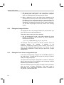
❏
This manual uses an icon like the one to the left to identify information
that is specific to a particular type of system. For example, this icon
identifies information that applies if you are using Codec Engine on a
dual-processor GPP+DSP system.
Trademarks
The Texas Instruments logo and Texas Instruments are registered
trademarks of Texas Instruments. Trademarks of Texas Instruments
include: TI, DaVinci, XDS, Code Composer, Code Composer Studio,
Probe Point, Code Explorer, DSP/BIOS, RTDX, Online DSP Lab,
DaVinci, TMS320, TMS320C54x, TMS320C55x, TMS320C62x,
TMS320C64x, TMS320C67x, TMS320C5000, and TMS320C6000.
MS-DOS, Windows, and Windows NT are trademarks of Microsoft
Corporation.
UNIX is a registered trademark of The Open Group in the United States
and other countries.
Linux is a registered trademark of Linus Torvalds.
Solaris, SunOS, and Java are trademarks or registered trademarks of
Sun Microsystems, Inc.
All other brand, product names, and service names are trademarks or
registered trademarks of their respective companies or organizations.
iv
This is a draft version printed from file: ce_serv_integTOC.fm on 9/25/07
Contents
1
Codec Engine Overview . . . . . . . . . . . . . . . . . . . . . . . . . . . . . . . . . . . . . . . . . . . . . . . . . . . . .1-1
This chapter introduces the Codec Engine.
1.1
What is the Codec Engine? . . . . . . . . . . . . . . . . . . . . . . . . . . . . . . . . . . . . . . . . . . . . . .1-2
1.2
Why Should I Use It? . . . . . . . . . . . . . . . . . . . . . . . . . . . . . . . . . . . . . . . . . . . . . . . . . . .1-3
1.3
Where Does the Codec Engine Fit into My Architecture? . . . . . . . . . . . . . . . . . . . . . . .1-4
1.4
What Are the User Roles? . . . . . . . . . . . . . . . . . . . . . . . . . . . . . . . . . . . . . . . . . . . . . . .1-6
1.4.1
Algorithm Creator . . . . . . . . . . . . . . . . . . . . . . . . . . . . . . . . . . . . . . . . . . . . . .1-6
1.4.2
Server Integrator . . . . . . . . . . . . . . . . . . . . . . . . . . . . . . . . . . . . . . . . . . . . . .1-7
1.4.3
Engine Integrator . . . . . . . . . . . . . . . . . . . . . . . . . . . . . . . . . . . . . . . . . . . . . .1-8
1.4.4
Application Author . . . . . . . . . . . . . . . . . . . . . . . . . . . . . . . . . . . . . . . . . . . . .1-8
1.5
Where Can I Get More Information? . . . . . . . . . . . . . . . . . . . . . . . . . . . . . . . . . . . . . . .1-9
2
Configuring a Codec Server . . . . . . . . . . . . . . . . . . . . . . . . . . . . . . . . . . . . . . . . . . . . . . . . . .2-1
This chapter describes how the Server Integrator should configure a Codec Server for use by the
Engine Integrator.
2.1
Overview. . . . . . . . . . . . . . . . . . . . . . . . . . . . . . . . . . . . . . . . . . . . . . . . . . . . . . . . . . . . .2-2
2.1.1
What is a Codec Server? . . . . . . . . . . . . . . . . . . . . . . . . . . . . . . . . . . . . . . . .2-3
2.1.2
What is the Execution Flow? . . . . . . . . . . . . . . . . . . . . . . . . . . . . . . . . . . . . .2-3
2.1.3
What About Single-Processor Systems? . . . . . . . . . . . . . . . . . . . . . . . . . . . .2-5
2.1.4
What Algorithms Can a Codec Server Integrate? . . . . . . . . . . . . . . . . . . . . .2-6
2.1.5
What Examples Exist? . . . . . . . . . . . . . . . . . . . . . . . . . . . . . . . . . . . . . . . . . .2-6
2.1.6
What is the Config Kit?. . . . . . . . . . . . . . . . . . . . . . . . . . . . . . . . . . . . . . . . . .2-6
2.2
Creating a Codec Server . . . . . . . . . . . . . . . . . . . . . . . . . . . . . . . . . . . . . . . . . . . . . . . .2-7
2.2.1
Creating a Package . . . . . . . . . . . . . . . . . . . . . . . . . . . . . . . . . . . . . . . . . . . .2-7
2.2.2
Editing the Package Definition . . . . . . . . . . . . . . . . . . . . . . . . . . . . . . . . . . . .2-8
2.2.3
Editing the Codec Server Configuration Script. . . . . . . . . . . . . . . . . . . . . . . .2-8
2.2.4
Editing the DSP/BIOS Configuration Script . . . . . . . . . . . . . . . . . . . . . . . . .2-14
2.2.5
Editing the Build Script . . . . . . . . . . . . . . . . . . . . . . . . . . . . . . . . . . . . . . . . .2-15
2.2.6
Editing the Linker Command File . . . . . . . . . . . . . . . . . . . . . . . . . . . . . . . . .2-16
2.2.7
Editing the main.c File . . . . . . . . . . . . . . . . . . . . . . . . . . . . . . . . . . . . . . . . .2-16
2.2.8
Editing the makefile . . . . . . . . . . . . . . . . . . . . . . . . . . . . . . . . . . . . . . . . . . .2-16
2.3
Delivering a Codec Server . . . . . . . . . . . . . . . . . . . . . . . . . . . . . . . . . . . . . . . . . . . . . .2-16
2.3.1
Delivering Server Packages for Servers Built with XDC . . . . . . . . . . . . . . .2-17
2.3.2
Delivering Server Packages for Servers Built with Configuro-based makefiles .
2-17
v
-vi
Chapter 1
Codec Engine Overview
This chapter introduces the Codec Engine.
Topic
Page
1.1
What is the Codec Engine? . . . . . . . . . . . . . . . . . . . . . . . . . . . . . . . . 1–2
1.2
Why Should I Use It? . . . . . . . . . . . . . . . . . . . . . . . . . . . . . . . . . . . . . . 1–3
1.3
Where Does the Codec Engine Fit into My Architecture? . . . . . . . . 1–4
1.4
What Are the User Roles? . . . . . . . . . . . . . . . . . . . . . . . . . . . . . . . . . 1–6
1.5
Where Can I Get More Information? . . . . . . . . . . . . . . . . . . . . . . . . . 1–9
1-1
What is the Codec Engine?
1.1
What is the Codec Engine?
From the application developer’s perspective, the Codec Engine is a set
of APIs that you use to instantiate and run xDAIS algorithms. A VISA
interface is provided as well for interacting with xDM-compliant xDAIS
algorithms.
The API is the same for all of the following situations:
P
+DS
P
P
G
❏
The algorithm may run locally (on the GPP) or remotely (on the DSP).
❏
The system may be a GPP+DSP, DSP only, or GPP only system.
❏
All supported GPPs and DSPs have the same API.
❏
All supported operating systems have the same API. For example,
Linux, PrOS, VxWorks, DSP/BIOS, and WinCE.
This manual uses an icon like the one to the left to identify information
that is specific to a particular type of system. For example, this icon
identifies information that applies if you are using Codec Engine on a
dual-processor GPP+DSP system.
xDM is the eXpressDSP Algorithm Interface Standard for Digital Media.
It is sometimes referred to as xDAIS-DM.
Any xDM algorithm is compliant with the eXpressDSP Algorithm Interface
Standard (xDAIS). Additionally, it implements the xDAIS-DM (xDM)
interface, an extension to the xDAIS standard that provides support for
digital media encoders, decoders, and codecs. The xDM specification
defines APIs for digital media codecs by class, with extensions defined
for video, imaging, speech, and audio codec classes.
The xDM interfaces divide codec algorithms into four classes: Video,
Image, Speech, and Audio (VISA). VISA reflects this xDM interface. One
set of APIs is provided per codec class. Thus, MP3 can be replaced with
WMA without changing the application source code. Only the
configuration needs to be changed.
The Codec Engine also supports real-time, non-intrusive visibility into
codec execution. It provides APIs for accessing memory and overall CPU
usage statistics and execution trace information.
The Codec Engine runtime is supplied in binary form. Thus, application
libraries built with same Codec Engine release are always compatible.
1-2
Why Should I Use It?
1.2
Why Should I Use It?
The Codec Engine is designed to solve some common problems
associated with developing system-on-a-chip (SoC) applications. The
most significant problems include:
P
+DS
GPP
❏
Debugging in a heterogeneous processor environment can be
painful. There are multiple debuggers and complex bootstrapping.
❏
Different implementations of the same algorithm, such as MP3, have
different APIs. Changing to a more efficient algorithm involves
significant recoding.
❏
Portability issues are compounded with two processors. You may
want to port to a different board with a newer DSP or a newer GPP.
❏
Some algorithms may run on either the GPP or the DSP. To balance
system load, “low complexity” algorithms can run on a GPP, but the
definition of “low” changes over time. If changing the location where
the algorithm runs were easy, you wouldn’t have to weigh
performance issues against the difficulty of changing the application.
❏
For market success, most applications need to support multiple
codecs to handle the same type of media. For example, an
application might need to support three or four audio formats.
❏
Programmers with a GPP (general-purpose processor) view don’t
want to have to learn to be DSP programmers. They don’t want to
have to worry about a DSP’s complex memory management and
DSP real-time issues.
The Codec Engine addresses these problems by providing a standard
software architecture and interfaces for algorithm execution. The Codec
Engine is:
❏
Easy-to-use. Application developers specify what algorithm needs
to be run, not how or where.
❏
Extensible and configurable. New algorithms can be added by
anyone, using standard tools and techniques.
❏
Portable. The APIs are target, platform, and even codec
independent.
Codec Engine Overview
1-3
Where Does the Codec Engine Fit into My Architecture?
1.3
Where Does the Codec Engine Fit into My Architecture?
The application code (or the middleware it uses) calls the Codec Engine
APIs. Within the Codec Engine, the VISA APIs use stubs and skeletons
to access the core engine and the actual codecs, which may be local or
remote.
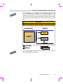
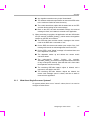
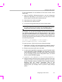
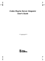
The following figure shows the general architecture of an application that
uses the Codec Engine. It also shows the user roles involved in creating
various portions of the application. See Section 1.4, What Are the User
Roles? for more on user roles.
Role 4:
Application
Author
Application
media middleware
Codec Engine Runtime
Core Engine APIs
Core Engine
Runtime
Role 2:
Server
Integrator
VISA APIs
Core Engine SPIs
Role 3:
Engine
Integrator
Video Encode
stubs
Video Encode
skeleton
VISA SPIs
Role 1:
Algorithm
Creator
MP4 Encode
VC1 Encode
The application (or middleware it uses) calls the core Engine APIs and
the VISA APIs. The VISA APIs use stubs to access the core engine SPIs
(System Programming Interfaces) and the skeletons. The skeletons
access the core engine SPIs and the VISA SPIs. The VISA SPIs access
the underlying algorithms.
1-4
Where Does the Codec Engine Fit into My Architecture?
G
DSP
PP+
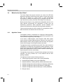
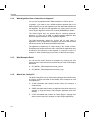
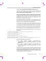
The following figure is a modification of the previous diagram that shows
how this architecture is distributed in a GPP+DSP system. In this
example, yellow portions run on the GPP, and grey portions run on the
DSP. This is, the video encoder skeleton and the video encoder codecs
are on the DSP and the application and video encoder stubs are on the
GPP.
Application
media middleware
Codec Engine Runtime
Core Engine APIs
Core Engine SPIs
Core Engine
Runtime
VISA APIs
Video Encode
stubs
…
Video Encode
skeleton
VISA SPIs
app processor
DSP Server
l on
loca
ly
MP4 Encode
VC1 Encode
Since Codec Engine is flexible, alternate diagrams could be shown for
GPP-only and DSP-only systems.
Codec Engine Overview
1-5
What Are the User Roles?
1.4
What Are the User Roles?
The Codec Engine has several customer use cases, from GPP-side
application developers to DSP-side codec authors. Is some cases, these
roles may be played by a single person. In other development
environments, a different developer may be assigned each role. This
topic describes the primary roles that Codec Engine users will play.
Because Codec Engine is very portable and configurable and can run in
many different environments, the descriptions of these roles are
intentionally generalized. When applicable, specific hardware and
software environments are described after the general descriptions.
This document describes the APIs available to the Application Author.
Other documents are referenced for the other roles.
1.4.1
Algorithm Creator
The Algorithm Creator is responsible for creating an xDAIS algorithm,
and providing the necessary packaging to enable these algorithms to be
consumed and configured by Codec Engine.
If the codec is xDM-compliant, Codec Engine's VISA APIs support
remote execution without additional support. However, if the codec is not
xDM-compliant, and the codecs support remote execution, the Algorithm
Creator should supply Codec Engine skeletons and stubs.
The Algorithm Creator uses xDAIS and the XDC Tools, which includes a
configuration kit. Using these, the Algorithm Creator generates a codec
library with the iAlg and optional iDMA3 interface symbols exported. This
person also implements the ti.sdo.ce.ICodec interface, referencing the
exported symbols from the codec library.
The Algorithm Creator hands a released Codec package to the Server
Integrator. This likely includes one or more libraries and the XDC
package metadata.
The Algorithm Creator uses the following resources:
1-6
❏
Codec Engine Algorithm Creator User's Guide (SPRUED6)
❏
xDAIS-DM (Digital Media) User Guide (SPRUEC8)
❏
xDM API Reference. XDAIS_INSTALL_DIR/docs/html/index.html
❏
TMS320 DSP Algorithm Standard Rules and Guidelines (SPRU352)
❏
TMS320 DSP Algorithm Standard API Reference (SPRU360)
❏
TMS320 DSP Algorithm Standard Developer’s Guide (SPRU424)
❏
Example codecs
What Are the User Roles?
1.4.2
Server Integrator
To support Engines with remote codecs, a Codec Server must be
created. The Codec Server integrates the various components
necessary to house the codecs (e.g. DSP/BIOS, Framework
Components, link drivers, codecs, Codec Engine, etc.) and generates an
executable.
There are two configuration steps that the Codec Server Integrator must
perform, one to configure DSP/BIOS (through a Tconf script) and one to
configure "the rest" of the components (through XDC configuration of
Framework Components, Link, Codec Engine, etc).
The Server Integrator receives the various Codec packages from
Algorithm Creators. This person uses Codec Engine and its dependent
packages (DSP/BIOS, DSKT2, etc) along with the XDC Tools to create
the following:
❏
A server configuration file (.cfg)
❏
A server DSP/BIOS configuration file (.tcf)
❏
A simple main() routine to do minimal initialization
❏
A DSP executable created by executing the configuration scripts,
and compiling the output. This executable is a Codec Server.
The Server Integrator hands the DSP executable to the Engine Integrator
(preferably as a Codec Server package. The Server Integrator should
also provide a list of the codecs in the Codec Server.
The Server Integrator uses the following resources:
al o
loc
nly
❏
This manual
❏
Configuration Reference.
CE_INSTALL_DIR/packages/xdoc/index.html
❏
Example Codec Servers
For applications that use only local algorithms, the Codec Server is not
used, so this role is not required.
Codec Engine Overview
1-7
What Are the User Roles?
1.4.3
Engine Integrator
The Engine Integrator defines various Engine configurations. This can
include the names of the Engines, as well as the codecs and their names
within each Engine, whether each codec is local or remote relative to the
application, which groups each codec should be integrated into (for
environments which support resource sharing), the name of the Codec
Server image if a particular Engine contains remote codecs, etc. This is
done via an XDC configuration script (*.cfg).
This script, when run, generates code and build instructions appropriate
for the configuration.
The Engine Integrator receives the name of a Codec Server and a list of
the codecs it contains from the Server Integrator. Using these, this
person creates an Engine configuration file (.cfg) that may reference a
Codec Server. (On local-only platforms, the Codec Server is not used.)
The Engine Integrator hands the Engine configuration file to the
Application Author.
The Engine Integrator uses the following resources:
1.4.4
❏
Chapter 5 of Codec Engine Application Developer’s Guide
(SPRUE67)
❏
Configuration Reference.
CE_INSTALL_DIR/packages/xdoc/index.html
❏
Example Build and Run Instructions.
CE_INSTALL_DIR/examples/build_instructions.html
❏
Example configuration scripts (*.cfg)
Application Author
The application uses the Codec Engine APIs (Engine_, VISA, and other
utility APIs) to create/delete preconfigured Engine instances,
create/delete and interact with codecs, acquire buffers appropriate for the
codecs, etc.
Since Codec Engine doesn't perform any I/O, the application is
responsible for handling I/O. This includes such task as file access (for
example, open/read/write/seek/close) and driver interaction (for
example, open/close/ioctl and buffer management).
The Application Author is responsible for building the application code,
and for linking "the appropriate content" into the executable image.
The Application Author receives the following:
1-8
Where Can I Get More Information?
❏
Various Codec packages from Algorithm Creators
❏
A Codec Server DSP executable from the Server Integrator if codec
will run on a DSP
❏
An Engine config file (.cfg) from the Engine Integrator
The Application Author write application code, generates output from the
Engine configuration file (.c and .xdl output files) using the XDC Tools,
compiles the application code and generated files. This person then links
the files, including the generated linker command file (.xdl) into an
executable. The end result is the application executable.
The process for generating an application executable is highly dependant
on the application's operating system. If the application runs on the DSP
using DSP/BIOS, for example, a .tcf file is needed to configure the
DSP/BIOS kernel as well. If the application runs on Linux, the application
does not need to configure the operating system.
The Application Author uses the following resources:
1.5
❏
Codec Engine Application Developer’s Guide (SPRUE67)
❏
Codec Engine API Reference.
CE_INSTALL_DIR/docs/html/index.html
❏
Example Build and Run Instructions.
CE_INSTALL_DIR/examples/build_instructions.html
Where Can I Get More Information?
The release_notes.html file at the top of the Codec Engine installation
provides general information, information about changes in the latest
version, devices supported and validation information, known issues, and
links to online documentation provided with the Codec Engine. The
online documentation provided with the Codec Engine is as follows:
❏
Codec Engine API Reference.
CE_INSTALL_DIR/docs/html/index.html
❏
Configuration Reference.
CE_INSTALL_DIR/packages/xdoc/index.html
❏
Example Build and Run Instructions.
CE_INSTALL_DIR/examples/build_instructions.html
For information about xDM, see the xDAIS-DM (Digital Media) User
Guide (SPRUEC8).
Codec Engine Overview
1-9
1-10
Chapter 2
Configuring a Codec Server
This chapter describes how the Server Integrator should configure a
Codec Server for use by the Engine Integrator.
Topic
Page
2.1
Overview. . . . . . . . . . . . . . . . . . . . . . . . . . . . . . . . . . . . . . . . . . . . . . . . 2–2
2.2
Creating a Codec Server . . . . . . . . . . . . . . . . . . . . . . . . . . . . . . . . . . . 2–7
2.3
Delivering a Codec Server . . . . . . . . . . . . . . . . . . . . . . . . . . . . . . . . 2–16
2-1
Overview
2.1
Overview
As described in Section 1.4.2, Server Integrator, the Server Integrator
provides a Codec Server to the Engine Integrator. In practice, these roles
may be shared by one person.
There are two configuration steps that the Server Integrator performs:
❏
Configure DSP/BIOS through a Tconf script
❏
Configure "the rest" of the components through XDC configuration of
Framework Components, DSP/BIOS Link, the Codec Engine, etc.
The Server Integrator receives various Codec packages from Algorithm
Creators, as well as packages of other components in the system (for
example Framework Components and Codec Engine).
The Server Integrator uses Codec Engine and its dependent packages
(DSP/BIOS, DSKT2, etc.) along with the XDC Tools to create the
following:
❏
A server configuration file (.cfg)
❏
A server DSP/BIOS configuration file (.tcf)
❏
A simple main() routine to do minimal initialization
❏
A DSP executable created by executing the configuration scripts,
and combining the various packages. This executable is a Codec
Server.
The Server Integrator should also provide a list of the codecs in the
Codec Server.
The Server Integrator hands the DSP executable to the Engine
Integrator, who references it in the Engine configuration file. For example,
the ceapp.cfg file might contain an Engine configuration and the following
line to identify the Codec Server used by the Engine.
vcr.server = "./video_copy.x64P";
2-2
Overview
2.1.1
What is a Codec Server?
A Codec Server is a binary that integrates codecs, framework
components, and system code. When the Codec Server is on a DSP, it
uses DSP/BIOS as the DSP kernel.
SP
P+D
P
G
In the context of the DaVinci DM644x platforms (and other GPP+DSP
platforms), a Codec Server is a DSP binary. It includes a DSP/BIOS task
thread that responds to requests from a client to create codecs, provide
performance information (MIPS and MEM usage).
A Codec Server performs similarly to a web server. Just as the term "web
server" can refer to the actual hardware, the configured software, or the
executing daemon, the term "Codec Server" can refer to the DSP, the
configured image loaded on the DSP, or the executing task.
The GPP application uses the VISA APIs to invoke remote codecs on the
DSP. From the perspective of the GPP application, codec execution is
completely transparent, and behaves the same whether the codecs are
local (on the GPP) or remote (on the DSP). When remote, Codec Engine
automatically manages the necessary creation, communication,
invocation, and eventual deletion of codecs from the DSP.
2.1.2
What is the Execution Flow?
As an example of the execution flow, on a dual-CPU system, such as the
DM644x device, the following steps summarize the execution flow when
a GPP application uses a remote codec to perform audio encode on the
DSP. After opening the engine, the application makes calls to the VISA
APIs, which manage the three phases of remote codec execution as
follows:
1) The application calls the VISA creation API (for example,
AUDENC_create() ) to create an algorithm instance on the DSP:
■
First, a generic instance object is created on the GPP to hold the
necessary state, handles, function pointers, etc.
■
A local "node" object is created to receive communication from
the "remote" node.
■
A "create" message is formed to signal the function dispatcher on
the DSP to create the remote node instance.
■
The creation message is sent to the dispatcher on the DSP.
■
On the DSP, the dispatcher receives the "create" message.
Some error checks are performed, and the DSP-side state
objects are created and initialized.
Configuring a Codec Server
2-3
Overview
■
A message queue is created to allow the remote node to receive
commands from the GPP.
■
The
node-specific
"create"
function
(for
example,
AUDENC_create() ) is called to initialize the node state and
algorithm-specific memory and resources. (Note that this call is
made from within the dispatcher execution context.)
■
A dedicated execution thread (task) is created for the node. The
new thread does not run yet, but is in a suspended state.
■
In the dispatcher thread, instance data for the new node is saved,
and then the dispatcher sends a status response back to the
GPP.
■
On success, the GPP-side instance object is updated with
appropriate handles and data for the new "remote" node.
■
A "start" message is then formed and sent to the dispatcher on
the DSP to start execution of the remote node.
■
Upon receiving the "start" command, the DSP-side dispatcher
changes the priority of the node's thread from suspended to its
configured execution priority. This change in priority causes the
node’s "execute" function to run in the newly created node's
execution context. This function blocks, awaiting commands
from the GPP.
2) The application calls the VISA process API (for example,
AUDENC_process() ), which results in a remote procedure call to the
DSP:
2-4
■
The GPP-side algorithm stub is invoked and performs some
basic argument validation.
■
A message structure is allocated and filled in with marshalled
arguments, including translated (DSP) physical addresses for
buffers.
■
The "process" message is sent to the remote node's message
queue on the DSP to invoke the remote algorithm.
■
On the DSP-side, the node's thread wakes upon receipt of the
"process" message, and calls the algorithm skeleton.
■
The skeleton unmarshalls the arguments and input and output
buffers and then invalidates the buffers from the DSP cache.
■
Any algorithm scratch memory is then "activated".
■
The algorithm's actual "process" function is invoked to do the
encoding.
Overview
■
Any algorithm scratch memory is then "deactivated".
■
The skeleton writebacks output buffers to ensure that CPU writes
to the cache are flushed to external memory.
■
The node's thread then replies with the status back to the GPP
and then blocks waiting for the next message.
■
Back on the GPP, the stub unmarshalls outArgs, the returned
message is freed, and a status is returned to the application
3) When processing is complete, the application calls the VISA delete
API (for example, AUDENC_delete() ), which causes the algorithm
instance on the DSP to be deleted:
2.1.3
■
The GPP-side forms and then sends a message to the remote
node on the DSP with a command to "exit".
■
On the DSP, the remote node wakes upon receipt of the "exit"
message and sends an acknowledgement back to the GPP.
■
On the GPP, a node "delete" message is formed and then sent
to the dispatcher on the DSP.
■
The dispatcher wakes up and deletes the remote node's
execution thread.
■
The
node-specific
"delete"
function
(for
example,
AUDENC_delete() ) is invoked to free algorithm resources and to
do any node-specific cleanup. (Note that this call is from within
the dispatcher execution context.)
■
The remaining DSP-side instance object is deleted, and a
response is sent back to the GPP.
■
The remaining GPP-side instance objects are deleted, the
remote node message queue is closed, and then a status is
returned to the application.
What About Single-Processor Systems?
On systems where there are no "remote" codecs, there is no need to
configure a Codec Server.
Configuring a Codec Server
2-5
Overview
2.1.4
What Algorithms Can a Codec Server Integrate?
You can use any algorithm that is xDM-compliant in a Codec Server.
In addition, if you want to use a xDAIS-compliant algorithm that is not
xDM-compliant, you can first implement your own stubs and skeletons for
that algorithm, and then use that algorithm in a Codec Server. See the
Codec Engine Algorithm Creator User’s Guide (SPRUED6) for details.
The Codec Engine does not provide APIs for chaining algorithms.
However, you may use an xDM- or xDAIS-compliant algorithm that,
behind its exposed interface, chains algorithms together.
The xDM specification defines an uniform API for each class of
algorithms. From an application perspective this means that the same
API will be used for an H.264 and an MPEG-4 decoder.
The algorithm is identified by an unique string in the "create" function.
Everything else should remain the same. Note that the application must
be aware of the restrictions of the algorithm it is trying to invoke. For
example TI video decoders expect one frame of data to work properly.
2.1.5
What Examples Exist?
You can use the Codec Servers as examples for creating your own
Codec Servers. These servers are provided as part of the Codec Engine
distribution.
2.1.6
❏
CE_INSTALL_DIR/examples/servers/all_codecs
❏
CE_INSTALL_DIR/examples/servers/video_copy
What is the Config Kit?
The XDC Config Kit is a set of configuration packages and tools that may
be used to configure and build an executable. Some examples of such
executables are:
2-6
❏
A DSP executable that contains remote codecs (for example, a
Codec Server)
❏
A DSP executable that contains an application and local codecs (for
example, a single processor Codec Engine application plus local
codecs)
❏
A GPP executable that contains an Codec Engine, implying local
and/or remote codecs (for example, a Codec Engine application)
Creating a Codec Server
2.2
Creating a Codec Server
To create a Codec Server, you perform the following configuration steps:
❏
Configure DSP/BIOS through a Tconf script
❏
Configure "the rest" of the components through XDC configuration
(for example, Framework Components, DSP/BIOS Link, the Codec
Engine, etc.).
You will modify the following files:
❏
package.xdc. The package definition file.
❏
package.bld. The build script.
❏
servername.cfg. The Codec Server configuration script.
❏
servername.tcf. The DSP/BIOS configuration script.
Optionally, you may modify the following additional files:
❏
link.cmd. An optional linker command file.
❏
main.c. Contains applications main() function.
To begin creating a Codec Server, use the steps in the following
subsections.
The
examples
in
this
section
use
the
CE_INSTALL_DIR/examples/servers/video_copy example.
So long as the algorithms you want to use implement the xDM interface,
the coding needed is limited to a simple main() routine in C code to
initialize the Codec Engine. The rest of the integration is by providing
configuration information to create the Codec Server.
2.2.1
Creating a Package
Follow these steps to set up environment variables to point to various
tools used in the build process and to create a directory with files you will
modify to create your server.
1) Optionally copy the entire CE_INSTALL_DIR/examples tree to a
working directory. This step is optional but recommended so that you
have a backup copy.
2) Edit the examples/user.bld file, which defines the locations of content
on your development system. Make sure the paths in this file match
your paths to the TI codegen tools and other compilers and OS tools
referenced in the file. See examples/build_instructions.html for
details.
Configuring a Codec Server
2-7
Creating a Codec Server
3) Edit the examples/xdcpaths.mak file with a text editor to specify the
CE_INSTALL_DIR, XDC_ROOT, and BIOS_ROOT variables.
Again, see examples/build_instructions.html for details.
4) Make a duplicate of one of the Codec Server examples in the
examples/servers directory. Each of these directories is a "package".
Packages must have names that match their directory location. So,
you should give your duplicate directory a path that follows the
examples/my_company/my_project/my_server naming convention.
You will name the package to match this location in the following
section.
2.2.2
Editing the Package Definition
The package.xdc file is the package definition file, which defines your
Codec Server’s name and its dependencies.
Follow these steps to name your server package.
1) Edit the package.xdc file with a text editor. Rename the server
package. For example, to call your server "my_server", change the
bolded portion as follows:
package my_companyname.my_project.my_server
The package name must reflect the directory structure under the
examples
directory.
For
example,
a
package
in
the
example/my_company/my_project/my_server directory must have a
name of my_company.my_project.my_server. You should use this
companyname convention to ensure that your server has a unique
package name.
2.2.3
Editing the Codec Server Configuration Script
A file named servername.cfg configures the non-DSP/BIOS aspects of
the Codec Server. To create this file for your own server, it is best to
modify an existing example file.
The syntax used in this Server configurations is based on JavaScript,
which is also used for the Tconf language used to statically configure
DSP/BIOS. (See SPRU007 for details.)
Unlike the JavaScript used in web pages, an object model is provided to
meet the needs of Engine configuration. This object model is
documented in the Configuration Reference, which is available at
CE_INSTALL_DIR/xdoc/index.html.
2-8
Creating a Codec Server
To see documentation for the attributes of the Server module, follow
these steps:
1) Open CE_INSTALL_DIR/xdoc/index.html to see the Configuration
Reference. Depending on your browser, you may need to enable
active content to view the list of nodes on the left.
2) Click the link to the ti.sdo.ce package.
3) Click the link to the Server module.
4) You see the config params that you can set for this module.
Note: To navigate backward in this window, click the "Back" link in
the upper-right corner of the window. The usual Back button in your
browser does not function correctly in this online help system.
For example, you see that the threadAttrs structure has several fields.
The following statements cause the Server module in the ti.sdo.ce
package to be made available to the configuration script. It then sets the
threadAttrs.priority attribute of the Server module to Server.MINPRI. This
indicates that the task threads created by the Codec Server should run at
the minimum priority level.
var Server = xdc.useModule('ti.sdo.ce.Server');
Server.threadAttrs.priority = Server.MINPRI;
To create your own *.cfg file for your server, follow these steps:
1) Rename the *.cfg file in your server directory to match the name of
your server. For example, your file might be called "my_server.cfg".
2) Edit the servername.cfg file with a text editor.
3) In order to allow application developers to use the TraceUtil module
on the GPP side to gather DSP/BIOS log information, you must
enable DSP/BIOS logging in your DSP server image. If the following
line is not already in your server's configuration script, you should
add it to enable DSP/BIOS logging:
var LogServer = xdc.useModule('ti.sdo.ce.bioslog.LogServer');
4) Modify the statements that get codec modules to reference the codec
modules you want to use. Use the package name from your codec
provider. Example codecs are available in the "examples" repository
beginning with the "codecs" namespace (that is, the
examples\codecs directory). Your codecs should be "well named"
beginning with your company name to produce unique package
names.
Configuring a Codec Server
2-9
Creating a Codec Server
For example, these statements from the video_copy.cfg file have
been modified (bold text) to reference the speech encoder/decoder.
/* get various codec modules; i.e. codec implementations */
var SPHDEC_COPY = xdc.useModule('codecs.sphdec_copy.SPHDEC_COPY');
var SPHENC_COPY = xdc.useModule('codecs.sphenc_copy.SPHENC_COPY');
5) Modify the attributes of the threadAttrs structure as desired. See
CE_INSTALL_DIR/xdoc/index.html for details about these attributes.
Server.threadAttrs.stackSize = 2048;
Server.threadAttrs.priority = Server.MINPRI;
These settings configure the Server thread, which is used to create
and delete codecs as well as to support requests for dynamic
resource usage. We recommend that you use Server.MINPRI so you
don’t preempt real-time threads.
6) Specify the algorithms to be available in this Codec Server by
modifying the Server.algs array. For example, statements from the
video_copy.cfg file have been added and modified (bold text) to
reference the speech encoder/decoder and to give audio processing
a higher priority than video processing.
Server.algs = [
{name: "viddec_copy", mod: VIDDEC_COPY, threadAttrs: {
stackSize: 4096, stackMemId: 0, priority: Server.MINPRI
},
{name: "videnc_copy", mod: VIDENC_COPY, threadAttrs: {
stackSize: 4096, stackMemId: 0, priority: Server.MINPRI
},
{name: "sphdec_copy", mod: SPHDEC_COPY, threadAttrs: {
stackSize: 4096, stackMemId: 0, priority: Server.MINPRI
},
{name: "sphenc_copy", mod: SPHENC_COPY, threadAttrs: {
stackSize: 4096, stackMemId: 0, priority: Server.MINPRI
},
];
+ 1}
+ 1}
+ 2}
+ 2}
7) The example *.cfg files also configure the ti.sdo.fc.dskt2.DSKT2 and
ti.sdo.fc.dman3.DMAN3 modules, which are part of Framework
Components. DSKT2 is the xDAIS algorithm memory allocation
manager, and DMAN3 is the DMA manager. See the Framework
Components documentation in CE_INSTALL_DIR/xdoc/index.html
for details on configuring these modules.
2-10
Creating a Codec Server
2.2.3.1
Controlling I/O Buffer Caching for xDM 0.9 Codecs
The DSP server's support—the "skeletons"—for remote execution of
codecs written for xDM 0.9 always manages the cache for all codec I/O
buffers exchanged with the ARM application.
This can be a performance problem for some video codecs, where the
codec accesses the buffers exclusively via DMA, yet the generic skeleton
invalidates and flushes those buffers anyway, thus wasting up to a few
milliseconds for every frame. (In xDM 1.0 codecs, this cache
management is negotiated automatically.)
To disable management for specific buffers, you need to determine the
type of buffer and its number, then set the cache management field for
the buffer to "false", as shown in the following example.
The first step is to determine the buffer type. Supported buffer types are:
"in" and "out" for both video encoders and video decoders, "recon" (short
for reconstruction) for video encoders, and "display" for video decoders.
Next, determine the number of the buffer you want to manage. Buffers
are numbered 0 to 15. You're typically looking for buffer number 0 or 1.
Finally, set the buffer's cache management field to "false" as shown in
this example:
var H264ENC = xdc.loadModule( "ti.sdo.codecs.h264enc.H264ENC" );
// don't cache-manage inbuf #0:
H264ENC.manageInBufsCache[0] = false;
// don't cache-manage outbuf #1:
H264ENC.manageOutBufsCache[1] = false;
// don't manage any of the reconstruction buffers:
H264ENC.manageReconBufsCache = [ false, false, false, false, false, false, false,
false, false, false, false, false, false, false, false, false ];
The cache management array names are:
❏
For
video
encoder
modules.
manageInBufsCache[],
manageOutBufsCache[], manageReconBufsCache[], each with
elements 0..15.
❏
For
video
decoder
modules.
manageInBufsCache[],
manageOutBufsCache[], manageDisplayBufsCache[], each with
elements 0..15.
Always check with a codec producer first to determine whether it is safe
to turn off cache management for certain buffers. When it comes to cache
mis-management, things might appear to work on your system for some
data and in some configurations, but will not work for other data and
configurations (that your customer may use).
Configuring a Codec Server
2-11
Creating a Codec Server
2.2.3.2
Codec
Specifying "Scratch Group" and DMA Resources for a
When you put together several codecs into a single DSP server, you may
need to make them share memory and DMA resources.
Two codecs can share what is called a "scratch" memory. This is a
working memory area, typically in fast internal memory, that is initialized
before one frame of data is processed and discarded afterwards. The
codecs can share this memory only if they run at the same priority. That
is, one cannot preempt another and thus destroy the other codec's
scratch area in the middle of its work.
Scratch area sharing is managed by the DSP algorithm memory manager
called DSKT2, but you can affect how it manages the scratch areas by
defining the optional groupId field for each algorithm in the array of
Server.algs[] configuration.
If you do not set the groupId field, no sharing will take place. This is fine
if you have enough internal/external memory. Otherwise, you can set it
per algorithm, as is the case in the video_copy server example:
/* The array of algorithms this server can serve up.
* This array also configures details about the threads
* that will be created to run the algorithms
* (e.g. stack sizes, priorities, etc.). */
Server.algs = [
{
name:
"viddec_copy", // C name for the of codec
mod:
VIDDEC_COPY, // VIDDEC_COPY defined above
threadAttrs: {
stackMemId: 0, // BIOS MEM seg ID for task stack
priority:
Server.MINPRI + 1
// task priority
},
groupId:
0, // scratch group ID (see DSKT2 below)
},
{
name:
"videnc_copy",
mod:
VIDENC_COPY,
threadAttrs: {
stackMemId: 0,
priority:
Server.MINPRI + 1
},
groupId:
0,
},
];
2-12
Creating a Codec Server
How you define the groupId field can affect performance or whether a
codec can be created at all. For detailed information on shared scratch
memory, see the Framework Components documentation. You may
save some time by reading the commentary for the server configuration
script in the video_copy example, which is in <CE_install_dir>/examples
/ti/sdo/ce/examples/servers/video_copy/video_copy.cfg.
What is true for sharing memory is also true for sharing DMA resources
among codecs. Again, for details, please check the Framework
Components documentation or the commentary regarding the theory and
practice of DMA configuration in the video_copy configuration example in
the script referenced above.
2.2.3.3
More About the groupId Field
Note that although both the Server.algs[] and Engine.algs[] array have an
optional groupId field, there is a distinction between the Server.algs[] and
Engine.algs[] arrays. This makes sense, if you consider that DSP-based
algorithms on a DM644x (DSP+ARM) are configured into a Server, while
the same DSP-based algorithms on a DM643x (DSP only) are configured
into an Engine.
Server.algs[].groupId
For each algorithm in the respective algs[] array, if the optional groupId is
uninitialized, the algorithm will be configured into a group with other
algorithms that have their groupId field uninitialized and run at the same
priority. If no algorithms have both of these attributes, it will be in a unique
groupId.
Exactly which groupId it will be assigned into is non-deterministic.
Therefore, it's not possible to configure scratch resources (for example,
DSKT2 scratch memory and DMAN3 DMA resources) for this nondeterministic groupId. It's important therefore, that if the system integrator
intends for an algorithm's resources to be shared, the groupId field
should be appropriately configured.
Also, if the groupId is non-deterministically assigned, and the algorithm
requests scratch resources, these resources will be granted from (likely
non-configured) resource pools!
For example, in DSKT2-based systems, DSKT2 grants such memory
requests
using
the
(likely
non-configured)
DSKT2.DARAM_SCRATCH_SIZES[<nondeterministic-groupId>]
and
DSKT2.SARAM_SCRATCH_SIZES[<nondeterministic-groupId>]
memory blocks. This can lead to strange system behavior, including
algorithms that sometimes can be created but other times fail.
Configuring a Codec Server
2-13
Creating a Codec Server
Engine.algs[].groupId
For each local algorithm, if the optional groupId field is uninitialized, the
algorithm is configured into its own, unique groupId. This is because we
don't know what priority the algorithm will run at, so we place it into a
unique group to prevent preemption by any other algorithm.
Note that for remote algorithms, the groupId field is ignored. In such
cases, the algorithm is placed into the Server-configured groupId.
2.2.4
Editing the DSP/BIOS Configuration Script
The Codec Server runs as a DSP/BIOS application on the DSP. As such,
it has a static DSP/BIOS configuration. This is created with a .tcf file as
described in the DSP/BIOS Tconf User’s Guide (SPRU007) and in the
DSP/BIOS online help. The syntax used in Tconf configurations is based
on JavaScript.
To create your own .tcf file for your server, follow these steps:
1) Copy all.tcf from CE_INSTALL_DIR/examples/servers/all_codecs to
your server directory. Rename it to match the name of your server.
For example, your file might be called "my_server.tcf".
2) Edit the servername.tcf file with a text editor.
3) Make any changes your Codec Server requires and save the file.
For the Codec Server, the task threads used to process algorithms are
created dynamically at runtime. This configuration file statically
configures several aspects of the DSP/BIOS kernel, including:
❏
The base DSP/BIOS kernel
❏
Memory section names, sizes, and locations
❏
Platform-specific attributes such as clock rates
❏
Enables the task manager and dynamic heap allocation
❏
Configures the C64+ L1 cache and corresponding memory segment
You can learn more about all of these modules and attributes in the
DSP/BIOS online help or the C6000 DSP/BIOS API Reference
(SPRU403).
You can add your own non-Codec Engine configuration items here if you
need to add your own functionality to the Server. The settings have been
tested for use with Codec Engine as is. You should be careful about
changing the settings.
2-14
Creating a Codec Server
2.2.4.1
DSP/BIOS Threads and Module Use
Each “remote” algorithm instance that runs on the DSP executes in a
DSP/BIOS thread whose priority is specified by a static configuration
parameter (see ti.sdo.ce.Server). The stack size of the thread that runs a
“remote” algorithm is specified by the algorithm’s implementation of the
ICodec interface (see ti.sdo.ce.ICodec).
The initial release of the Codec Engine runtime starts a separate thread
for each “remote” algorithm instance; thus, two instances of the same
algorithm run in two separate threads (even though these threads have
the same stack size and priority). Future releases may run these
instances in a single thread. However, algorithm instances that require
different priorities will always be run in separate threads.
Creation and deletion of algorithm instance threads is handled by a
Resource Manager Server (RMS) thread. This thread is part of the Codec
Engine Runtime and, by default, runs at the lowest possible priority so as
to avoid affecting real-time processing performed by “remote” algorithm
instances. The RMS thread also provides “resource monitoring” services
to the Codec Engine Runtime. For example, it reports overall DSP CPU
load to the GPP, transfers execution trace data from the DSP to the GPP,
and controls the acquisition of DSP trace information based on GPP
commands.
Although the Codec Engine uses the DSP/BIOS CLK services, the initial
release does not require timer interrupts and configures the DSP/BIOS
CLK interrupt to run once every 5 seconds. In the future, the Codec
Engine may require interrupts rates as high as 1/second to support
watchdog timers and recovery from IPC failures.
In order to support CPU load monitoring, the Codec Engine adds an idle
function to DSP/BIOS’s idle loop. The current implementation allows
other application-specified idle functions to also run. However, to support
low power modes of the DSP, future implementations may idle the CPU,
which prevents other idle functions from running.
Note that the changes mentioned in this section are not certain. We are
simply pointing out areas of the implementation that may be subject to
change in future releases.
2.2.5
Editing the Build Script
Edit the package.bld file with a text editor. This build script is run by the
makefile. In addition to compiling code, the build script runs the
DSP/BIOS and XDC configuration scripts and links the executables
together.
Configuring a Codec Server
2-15
Delivering a Codec Server
Change the bold text in the following line to match your server name:
var serverName = "my_server";
When you have finished development, you may want to change "debug"
in the following line to "release":
Pkg.attrs.profile = "release";
Do not edit package.mak, any files that begin with a period, or anything
in the "package" directory. These files are generated when you build. Any
modifications to these files are overwritten whenever you rebuild.
2.2.6
Editing the Linker Command File
If you want to specify any other DSP linker commands, add those
commands to the link.cmd linker command file.
2.2.7
Editing the main.c File
You may add to the main.c source file as necessary. Since DSP/BIOS
runs its threads after main() completes, you should only put initialization
statements in main(), and main() must run to completion rather than
looping.
2.2.8
Editing the makefile
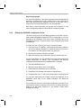
The makefile should not require changes. However, you may need to add
repositories to the XDC_PATH used in the makefile by modifying the
xdcpaths.mak file.
2.3
Delivering a Codec Server
To distribute a Codec Server, you should deliver the package used to
produce the server, including the server executable. The package
contains the configuration scripts that produced the server. The package
information also specifies the version of the compiler used to make the
server and the versions of the codecs used to make the server.
When you distribute a Codec Server, you should provide documentation
that includes the following information:
2-16
❏
Codec Server name
❏
Build options used for compiling and linking
❏
List of the algorithms available in the Codec Server
Delivering a Codec Server
In addition to including the server executable in the server package, you
must also add the generated package/info/* files to the package. These
files contain information in text form about the codecs included in the
server, the server's memory map, and other relevant information.
To create a deliverable package, we recommend you use the built-in
method in XDC to create a .tar package archive, as shown in the
following section.
2.3.1
Delivering Server Packages for Servers Built with XDC
If you built your server via XDC (that is, there is a "package.bld" file and
the makefile is very short), you need to add the directory "package/info"
to Pkg.otherFiles as follows to include the generated server info files in
the release:
Pkg.otherFiles = [ ...., "package/info", ... ];
Also, modify the makefile to run the "xdc release" step as the main goal
(differences shown in bold):
EXAMPLES_ROOTDIR := $(CURDIR)/../../../../../..
include $(EXAMPLES_ROOTDIR)/xdcpaths.mak
# add the examples directory to the list of paths to packages
XDC_PATH := $(EXAMPLES_ROOTDIR);$(XDC_PATH)
# include $(EXAMPLES_ROOTDIR)/buildutils/xdcrules.mak
# run "xdc release" to create a tar file with the server(s)
all:
$(XDC_INSTALL_DIR)/xdc release XDCPATH="$(XDC_PATH)" \
XDCOPTIONS=$(XDCOPTIONS) $@ -PD .
When you type "make", a .tar file will be created. That is your server
deliverable.
See ti/sdo/ce/examples/servers/all_codecs/package.bld for an example.
2.3.2
Delivering Server Packages for Servers Built with Configuro-based makefiles
If you built your server via Configuro (a utility that generates object and
linker files from a user .cfg script) that is driven from a makefile (which is
then not very short), you must add a step to the makefile to create a
server package and an archive from it.
Configuring a Codec Server
2-17
Delivering a Codec Server
DSP servers built with Configuro do not require a package to build the
server itself, but you must create one to produce a server deliverable. In
that package, you must include both the server executable and the
Configuro-generated "package/info/*" files.
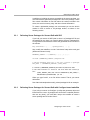
While each Configuro-using makefile is different, here's an example of
how the server package generation may look. Here we auto-generate an
XDC package from the given package name $(SERVER_PKG), given
the server executable name $(SERVER_EXE), and config name
$(CONFIGPKG), knowing that Configuro-generated files are in the
$(CONFIGPKG) directory:
SERVER_PKG := ti.sdo.ce.examples.servers.video_copy.evmDM6446
SERVER_PKG_ARCHIVE := $(subst .,_,$(SERVER_PKG)).tar
# create server release package and archive it; the package
# contains the executable and some meta-info files
$(SERVER_PKG_ARCHIVE): $(SERVER_EXE)
@echo "Creating server release:"
@rm -rf package package.*
@echo "package $(SERVER_PKG) {}" > package.xdc
@echo "Pkg.otherFiles = ['./$(SERVER_EXE)','package/info']" \
> package.bld
@mkdir package ; cp -R $(CONFIGPKG)/package/info package
@$(XDC_INSTALL_DIR)/xdc XDCPATH="$(XDC_PATH)" release
@rm -f package.bld package.mak .[idle]*
For this example to work, the makefile and the server executable must be
in
a
directory
whose
path
ends
with
"ti/sdo/ce/examples/servers/video_copy/evmDM6446", because that is
the name we have given to the server package.
See ti/sdo/ce/examples/servers/video_copy/evmDM6446/makefile for an
example.
2-18
This is a draft version printed from file: ce_serv_integIX.fm on 9/25/07
Index
A
D
algorithm 2-6
specifying 2-10
Algorithm Creator 1-6, 2-2
all.tcf file 2-14
API Reference 1-9
Application Author 1-8
array 2-11, 2-13, 2-14
debug version 2-16
delivering a Codec Server 2-16
directory for package 2-8
DMA 2-11
DMAN3 manager 2-10
documentation to provide 2-16
DSKT2 manager 2-10, 2-12, 2-13
DSP 1-2
DSP binary 2-3
DSP/BIOS 1-2
configuration 2-2, 2-14
kernel 2-14
modules 2-14
B
Back button 2-9
benefits of Codec Engine 1-3
binary file 2-3
BIOS_ROOT environment variable
buffer type 2-11
build instructions 2-7
build tools 2-6
build_instructions.html file 1-9
2-8
E
Engine Integrator 1-8, 2-2
environment variables 2-8
examples 2-6
C
cache 2-11
CE_INSTALL_DIR environment variable
.cfg file 2-7, 2-8
chaining algorithms 2-6
CLK services 2-15
Codec Engine 1-2
benefits 1-3
server 1-7
Codec Server 2-3
building 2-15
configuring algorithms 2-8
configuring DSP/BIOS 2-14
creating 2-7
delivering 2-16
documentation 2-16
Config Kit 2-6
Configuration Reference 1-9, 2-8
configuration script
*.cfg 2-7
*.tcf 2-7
CPU load 2-15
F
2-8
Framework Components 2-10
G
generated files 2-16
GPP 1-2
groupId field 2-12, 2-13, 2-14
I
idle loop
2-15
J
JavaScript language
2-8, 2-14
Index-1
Index
L
link.cmd file 2-7, 2-16
linker commands 2-16
Linux 1-2
local codecs 2-5
M
main.c file 2-7, 2-16
makefile 2-15, 2-16
middleware 1-4
MINPRI attribute 2-9
N
name of server
2-16
O
online help
1-9
P
package
creating 2-7
directory path 2-8
making a copy 2-8
naming 2-8
package directory 2-16
package.bld file 2-7, 2-15
package.mak file 2-16
package.xdc file 2-7, 2-8
path definitions 2-7
PrOS 1-2
server configuration 2-9
Server Integrator 1-7, 2-2
server name 2-16
Server, Codec 2-3
Server.algs array 2-10
servername.cfg file 2-8
single-processor systems 2-5
skeletons 1-4, 2-6
stubs 1-4, 2-6
T
task threads 2-3, 2-14, 2-15
.tcf file 2-7, 2-14
Tconf 2-8
configuration 2-7
threadAttrs structure 2-9
ti.sdo.ce package 2-9
ti.sdo.fc package 2-10
type of buffer 2-11
U
user roles 1-6
user.bld file 2-7
V
VISA API 1-2, 2-3
VxWorks 1-2
W
web server vs. Codec Server
WinCE 1-2
2-3
R
X
recon buffer 2-11
release version 2-16
release_notes.html file 1-9
roles 1-6
Algorithm Creator 1-6, 2-2
Application Author 1-8
Engine Integrator 1-8, 2-2
Server Integrator 1-7, 2-2
RTSC tools 2-6
xDAIS 1-2
compliance 2-6
related documents 1-6
xDAIS-DM 1-2
XDC Tools 1-6
XDC tools 2-6
XDC_PATH variable 2-16
XDC_ROOT environment variable
xdcpaths.mak file 2-8, 2-16
xDM
compliance 2-6
defined 1-2
related documents 1-6
version 0.9 vs. 1.0 2-11
S
scratch memory 2-12
Index-2
2-8