1
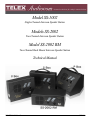
Model SS-1002
Single-Channel Intercom Speaker Station
Models SS-2002
Two-Channel Intercom Speaker Station
Model SS-2002 RM
Two-Channel Rack Mount Intercom Speaker Station
Technical Manual
9350-7741-000 Rev E
07/2009
PROPRIETARY NOTICE
Shipping to the Manufacturer
The product information and design disclosed herein were originated by
and are the property of Bosch Security Systems, Inc. Bosch reserves all
patent, proprietary design, manufacturing, reproduction, use and sales
rights thereto, and to any article disclosed therein, except to the extent
rights are expressly granted to others.
All shipments of product should be made via UPS Ground, prepaid (you
may request from Factory Service a different shipment method). Any
shipment upgrades will be paid by the customer. The equipment should
be shipped in the original packing carton. If the original carton is not
available, use any suitable container that is rigid and of adequate size. If
a substitute container is used, the equipment should be wrapped in paper
and surrounded with at least four (4) inches of excelsior or similar
shock-absorbing material. All shipments must be sent to the following
address and must include the Proof of Purchase for warranty repair.
Upon completion of any repair the equipment will be returned via
United Parcel Service or specified shipper, collect.
COPYRIGHT NOTICE
Copyright 2009 by Bosch Security Systems, Inc. All rights reserved.
Reproduction, in whole or in part, without prior written permission from
Bosch is prohibited.
WARRANTY NOTICE
See the enclosed warranty card for further details.
CUSTOMER SUPPORT
Factory Service Department
Telex Communications, Inc.
8601 East Cornhusker Hwy.
Lincoln, NE 68507 U.S.A.
Attn: Service
This package should include the following:
Technical questions should be directed to:
QTY
Customer Service Department
Bosch Security Systems, Inc.
12000 Portland Avenue South
Burnsville, MN 55337 USA
Telephone: 800-392-3497
Fax: 800-323-0498
Factory Service: 800-553-5992
RETURN SHIPPING INSTRUCTIONS
Customer Service Department
Bosch Security Systems, Inc. (Lincoln, NE)
Telephone: 402-467-5321
Fax: 402-467-3279
Factory Service: 800-553-5992
Please include a note in the box which supplies the company name,
address, phone number, a person to contact regarding the repair, the type
and quantity of equipment, a description of the problem and the serial
number(s).
1
1
1
4
DESCRIPTION
SS-1002, 1 channel front plate assembly
OR
SS-2002, 2 channel front plate assembly
User Manual
Screw, Flat Head, 6-32 x 5/16”
PART NO.
9010-7741-000
9010-7741-001
9350-7741-000
51847-122
One of the following, depending on what was ordered:
1
P-box, 1-channel
9010-7627-007
1
S-box, w/handle, 1-channel
9010-7627-008
1
P-box, 2-channel
9010-7627-009
1
S-box, w/handle, 2-channel
9010-7627-010
1
U-box
9010-7627-004
1
S-box, w/out handle, 1-channel
9010-7627-011
1
S-box, w/out handle, 2-channel
9010-7627-012
1
Warranty Card
38110-390
2
End Caps
9310-7620-001
1
Statement of Conformity
38109-675
FCC Statement
This equipment uses, and can radiate radio frequency energy that may
cause interference to radio communications if not installed in
accordance with this manual. The equipment has been tested found to
comply with the limits of a Class A computing device pursuant to
Subpart J Part 15 of FCC Rules which are designed to provide
reasonable protection against such interference when operated in a
commercial environment. Operation of this equipment in a residential
area may cause interference which the user (at his own expense) will be
required to correct.
This product meets Electromagnetic Compatibility
Directive 89/336/EEC
1
4
1
1
1
SS-2002RM
SS-2002RM Final Assembly
Foot, bumper, black
User Instructions
Statement of Conformity
Warranty
9010-7742-000
56471-001
9350-7741-000
38109-675
38110-390
Table
of
Contents
INTRODUCTION ........................................................................................................................................ 3
Introduction ...............................................................................................................................................................3
Description ................................................................................................................................................................3
Features .....................................................................................................................................................................4
INSTALLATION .......................................................................................................................................... 7
Configuration Pre-check ...........................................................................................................................................7
DIP Switches .............................................................................................................................................................7
Mic Kill Receive ........................................................................................................................................................8
Call Signal Compatibility ..........................................................................................................................................8
Incoming Call Beep ...................................................................................................................................................8
Microphone Type .......................................................................................................................................................8
Speaker Beep for Incoming Call ................................................................................................................................9
Balanced/Unbalanced Switch ....................................................................................................................................9
Sidetone Trimmers .....................................................................................................................................................9
Headset Connector Notes ..........................................................................................................................................9
Panel Mic Connector Notes .......................................................................................................................................9
Intercom Channel Connections ...............................................................................................................................10
Description of Phantom-Powered Connection ........................................................................................................10
Description of Locally Powered Connection ..........................................................................................................11
All Locally Powered Intercom Stations (Dry Lines) ...............................................................................................12
OPERATION AND SPECIFICATIONS .................................................................................................. 15
Power Up .................................................................................................................................................................15
Sidetone Adjustment ................................................................................................................................................15
Channel Select (SS-2002 & SS-2002RM Only) .......................................................................................................16
Headset/Headphone/Speaker/Microphone Selection ..............................................................................................16
Receiving Calls ........................................................................................................................................................16
Calling an Intercom Channel ..................................................................................................................................17
Specifications ...........................................................................................................................................................18
Dimensions ..............................................................................................................................................................19
SS1002/2002 SUPPLEMENTAL INFORMATION ................................................................................. 21
Installing the Box to the Faceplate ..........................................................................................................................21
GENERAL INSTRUCTIONS .........................................................................................................................................................21
Notes ........................................................................................................................................................................23
CHAPTER 1
Introduction
Introduction
Thank you for purchasing the Audiocom SS-1002/2002/2002RM Intercom Speaker Station. We hope the many design features
of this product satisfies your intercommunication requirements for many years to come. To get the most out of you new
intercom stations, take a few moments to look through this manual before using the Intercom Speaker Stations for the first
time.
Description
The Intercom Speaker Stations may be used with a headset, or with the built-in speaker and panel microphone or an optional
gooseneck microphone. Another option is to use headphones and either the built-in panel microphone or an optional
gooseneck microphone. As an alternative to a headset, a telephone-style handset may also be used.
The SS-1002 is a single-channel station; the SS-2002 & SS-2002RM provide switch selectable access to either of two (2)
intercom channels. Both the SS-1002 and the SS-2002 come in three (3) versions to suit a variety of applications.
S Box -
The S box is a portable version. It has a carrying handle and dual loop-through intercom connectors which
permit stations to be quickly interconnected using pre-fabricated cables.
P Box -
The P box is stationary version. It also has dual loop-through connectors for quick interconnection, but the
case is designed for desktop or console-mount applications.
U Box -
The U box is designed for permanent, in-the-wall mounting. It uses push-type wire terminals for connection
to the intercom system.
NOTE:
In addition, the SS-2002RM can be used on a desktop or mounted in a standard 19” equipment rack (using the
optional RM-14 Rack Mount Kit).
3
Features
Use Figure 1 and Figure 2 to locate the features described below.
1.
Channel and Power Connections -
The U box uses quick release terminals to connect to audio and power wires.
For the S box and P box versions, the terminal connections are connected to
the dual, loop-through XLR connectors on the side of the box. These permit
several stations to be connected in a string, or daisy-chain, using prefabricated intercom cables.
2.
Configuration DIP Switches -
Controls the following features:
Call Beep- In addition to a flashing call key indication for incoming calls,
an incoming call beep tone can also be used.
Headset Microphone Type Selection- Either a balanced or unbalanced
dynamic microphone can be selected.
DC call enable- This may be turned on to use the intercom station with
intercom systems that use DC call signaling.
4
3.
Panel Mic Key -
Selects the Panel Mic/Built-in Mic connector (11) in the on position, the
headset connector (10) in the off position.
4.
Speaker Key -
Selects the built-in speaker in the on position, the headset connector (10) in
the off position.
5.
Channel Select Key
(SS-2002 & SS-2002RM only) -
Selects intercom channel 1 or 2. The key lights green for channel 1 and red for
channel 2
6.
Volume Control -
Adjusts intercom listen volume to headphones or speaker.
7.
Intercom Listen Key -
Both momentary (also known as push-to-listen) and latching (also known as
hands-free-listen) functions are possible.
8.
Call Key -
Use to send call signals on the intercom channel. Flashes for incoming calls.
9.
Intercom Talk Key -
Only the momentary (push-to-talk) function is possible. All models are
equipped with a mic kill receive circuit, which allows an operator at a remote
master station (such as the US-2000A) to turn off the talk key on all stations
along the intercom line.
10.
Dynamic-Mic Headset Connector -
4-pin male XLR connector accepts headsets with monaural headphones and
either a balanced or unbalanced dynamic microphone. Also accepts a
telephone style handset. It can be used with headphones when a panel mic is
connected. A handheld microphone along with the internal speaker can also
be used.
11.
Panel Mic Connector -
Accepts an electret gooseneck microphone such as the Telex MCP-90.
12.
Built-in Panel Microphone -
Active when the Panel Mic key is pressed and a gooseneck microphone is not
inserted in the Panel Mic connector.
13.
Sidetone Trimmers -
The sidetone trimmers adjust the level of the user’s own voice in the
headphones when using full-cushion headphones. When using the speaker or
open-ear style headphones, the sidetone trimmers are adjusted to eliminate the
user’s voice from the headphones or speaker. This helps to prevent feedback.
14.
Balanced/Unbalanced Selector
Switch -
This switch sets the intercom station for compatibility with either Audiocom
(balanced) or Clear-Com (unbalanced) intercom systems.
FIGURE 1.
SS-1002/2002 Features
5
FIGURE 2.
6
SS-2002RM Features
CHAPTER 2
Installation
Configuration Pre-check
Before making connections, read the following configuration notes. Make sure all internal controls are properly set for your
intended usage.
To access the internal controls, do the following:
1.
Remove the four (4) screws on the front panel that secure the intercom station faceplate to the mounting box.
2.
Pull the faceplate out for all versions (except the RM version).
To access the internal controls for the RM version, do the following:
1.
Remove the 10 screws securing the cover on the box.
2.
Lift the cover off.
DIP Switches
TABLE 1. DIP
Switch
Number
Switch descriptions and factory default settings
Description
Settings
Open = OFF; Closed = ON
Closed: Disabled, No Mic Kill
Open: Enabled, Mic Kill Active
Default
Settings
Open
1
Mic Kill Receive
2
Call Signal Method
Closed: DC (SW1 set to UNBAL)
Open: Audiocom (SW1 set to BAL)
Open
3
Incoming Call Beep
Closed: Disabled
Open: Enabled
Open
4
Microphone Type
Closed: Unbalanced
Open: Balanced
Open
5
Speaker Beep for Incoming
Call
Closed: Enabled (DIP switch 3 must be set to Open)
Open: Disabled
Open
6
Not Used
Not Defined
Open
7
Not Used
Not Defined
Open
8
Not Used
Not Defined
Open
7
Mic Kill Receive
Audiocom intercom stations, such as the US2002A, can transmit an inaudible signal to turn off the microphones in all remote
intercom stations on an intercom channel. This is useful when a remote intercom station has been left unattended with the
microphone on. The procedure to send a mic kill signal from a master station is a two-step process, so it is very unlikely
microphones are ever turned off by accident. However, you may wish to disable the Mic Kill Receive feature at the intercom
unit. You might do this, for example, if communications are of a very critical nature, where it is absolutely essential the
microphone never be remotely deactivated.
To enable the mic kill function, do the following:
> Set DIP switch 1 to the open position.
To disable the mic kill function, do the following:
> Set DIP switch 1 to the closed position.
Call Signal Compatibility
For Audiocom setup, do the following:
1.
Verify Dip Switch 2 is in the OPEN position.
2.
Verify the Balanced/Unbalanced switch is in the Balanced position.
For Clear-Com setup, do the following:
1.
Set DIP switch 2 to the CLOSED position.
2.
Set the Balanced/Unbalanced switch to the Unbalanced position.
Incoming Call Beep
Incoming calls are always indicated by a red flashing call key.
To set the incoming call beep in the headphones, do the following:
> Set DIP switch 3 to the OPEN position (default).
DIP switch 3 must also be in the OPEN position if you want to activate incoming call beep to the speaker using DIP
switch 5.
Microphone Type
If you are using a headset, telephone handset, or dynamic handheld microphone:
If the specifications indicate the microphone type is balanced, do the following:
> Set DIP switch 4 in the open (default) position.
If the specifications indicated an unbalanced microphone, do the following:
> Set this switch to the closed position.
NOTE:
8
If you are not sure, leave the switch in the open position for now. Try both positions during operations. Use the
position that produces the best audio quality at other stations.
Speaker Beep for Incoming Call
To set the speaker beep for incoming calls, do the following:
> Set DIP switch 5 to the closed position if you want to hear incoming call beep in the speaker.
NOTE:
DIP switch 3 must be in the open position.
Balanced/Unbalanced Switch
This switch is set at the factory to the Balanced (BAL) position for use with Audiocom intercom systems. Set the switch to the
Unbalanced, or UNBAL position for use with a Clear-Com intercom system.
Sidetone Trimmers
The Sidetone Trimmers are normally adjusted after all connections are completed. See “Sidetone Adjustment” on page 15.
FIGURE 3.
DIP Switch location RM version (left), SIP switch location S, U, and P Versions (right).
Headset Connector Notes
If you are using a monaural, dynamic-mic headset, or a monaural, telephone-style, dynamic-mic hands-free, or a handheld
dynamic microphone, plug it into the headset connector. You can also use this connector with monaural headphones for
listening when you are using either the built-in panel microphone or the optional gooseneck microphone for talk back.
Panel Mic Connector Notes
As an alternative to a headset or telephone style handset, you can use either the built-in panel microphone or an optional
gooseneck microphone.
To connect a Telex MCP-90 gooseneck microphone, do the following:
1.
Insert the 1/4” RTS connector into the panel microphone connector.
2.
Screw the microphone in.
9
When a gooseneck microphone is inserted in the panel microphone connector, the built-in panel microphone is automatically
bypassed. Use either of these microphones for talk back, then use the internal speaker for listening, or connect a pair of
headphones to the headset connector for private listening.
Intercom Channel Connections
The method of connection depends on the type of box. The S box, P box, and RM versions connect to the intercom system
using pre-fabricated cables in a phantom powered configuration. The U box version is designed for permanent installation, and
it can be either phantom powered or locally powered.
Description of Phantom-Powered Connection
In phantom-powered connections the operating power and intercom audio for the entire system are carried over the same
wires. The advantage of this method is simplicity of connection. The system power supply (PS-2001L, SPS-2001A, etc.)
automatically provides what is known as a terminating impedance for the intercom system. Without this terminating
impedance, the sound quality becomes distorted, and the levels shift every time additional stations are connected. The
disadvantage of the phantom power method is some operating power is lost over very long intercom cable runs, and
performance at distant intercom station may be reduced. Generally, if intercom stations are within a few hundred feet from the
system power supply, phantom power is sufficient. Also, increasing the number of stations reduces the overall operating
distance. Phantom-power is generally the only method used to connect the S box, P box, and RM versions. Figure 4 illustrates
a phantom-power intercom system.
NOTE:
The distance over which power can be delivered is less than the distance over which audio can be delivered.
Audio can be delivered for several miles to locally powered stations as described below.
FIGURE 4.
Example:
10
Phantom Powered Example
Figure 4 is an example of a phantom-powered system. In this system, a PS-2001L power supply is set to
isolate mode. Each channel is a separate party line and current per channel is limited to 1Amp. Both single and
two-channel intercom stations may be connected by using Y cables (or JB2 Junction boxes). Pre-fabricated
cables may be used, or cables may be constructed using the diagrams in Figure 10 on page 14.
Description of Locally Powered Connection
Using a Locally Powered Connection, an intercom station is connected to the intercom line just like any phantom powered
intercom station, except a local power supply is also connected. The external local power supply is located near the intercom
station and provides power for that station only.
Since power loss on the intercom lines is no longer an issue, the operating range is now limited only to the audio transmission
range, which is several miles. Another advantage to this method is more stations can be connected to the intercom channels.
When local power is supplied to an intercom station, the station detects it and automatically disconnects from the system’s
phantom-power supply.
Figure illustrates an intercom system with both phantom-powered and locally powered U boxes. As long as a system power
supply (PS2001L, SPS-2001, etc.) is located somewhere in the intercom system, the proper terminating impedance is still be
supplied for all stations. However, if all stations are locally powered, and there is not system power supply, a special line
termination must be installed.
FIGURE 5.
A 2-channel Audiocom intercom system using a PS2001L power supply.
A 2-channel Audiocom intercom system using a PS2001L power supply (as shown in Figure 5). The PS2001L is set to isolate
mode. In isolate mode, each intercom channel is a separate party line, and total current for each channel is limited to 1 Amp.
Both the SS-1002 and SS-2002 stations may be connected depending on each location’s need to communicate with one or two
channels. SS-1002 stations may be connected to either channel one or two. Also, note locally powered stations may be
connected. This is recommended when stations are installed at remote locations. Since the PS2001L provides termination for
the intercom channels, no user-installed termination is required.
11
All Locally Powered Intercom Stations (Dry Lines)
If intercom stations are widely distributed, you can dispense with a system power supply (PS2001L, SPS-2001, etc.) and use
local power for each station. When no power is delivered on the intercom channels, this is known as dry-line operation. Since
a system power supply is not used, a line termination must be inserted in each intercom channel for proper operation. Again,
not that only the U box has provisions for local power, the 3-pin connectors on the S, P, and RM version do not permit this type
of connection. Figure illustrates an intercom system using all locally powered U boxes.
FIGURE 6.
Intercom system using all locally powered U box stations.
An example (as shown in Figure 6) of an Audiocom intercom system using all locally powered U box stations, with no power
being distributed on the intercom channels (dry lines). Since an Audiocom power supply is not used, the installer must connect
a line termination somewhere in each channel for proper operation.
Audiocom mode line termination for dry-line operation. (One required for each channel).
The termination is available via P/N 9020-7550-000.
FIGURE 7.
12
Audiocom mode connections for an SS-1002 Intercom Station in a U box. For Clear-Com connection, use the
Unbalanced Mode Intercom Channel pin out information listed in “Specifications” on page 18.
FIGURE 8.
Audiocom mode connections for an SS-2002 Intercom Station in a U box. For Clear-Com connection, use the
Unbalanced Mode Intercom Channel pin out information listed in “Specifications” on page 18.
FIGURE 9.
13
FIGURE 10.
14
Audiocom cable wiring diagrams
CHAPTER 3
Operation and Specifications
Power Up
To power up the SS1002/2002, do the following:
1.
Verify the local power supplies are plugged in.
2.
Turn on the power switches of any phantom power supplies (PS-2001L, SPS-2001, etc.).
Sidetone Adjustment
The SS-1002/2002 and the SS-2002RM use full-duplex audio in which the talk and listen audio are sent and received on the
same wires when using a headset. The SS1002/2002 and the SS-2002RM use half-duplex audio when the speaker is used. A
certain amount of your own voice level is desirable (called sidetone) to overcome the muffled sensation when talking. The
sidetone adjustment is different for these operating conditions:
To adjust sidetone using an open-ear style headset or headphones, do the following
SS-2002 & SS-2002RM only:
1.
Activate channel 1 as described in “Channel Select (SS-2002 & SS-2002RM Only)” on page 16.
2.
Activate talk and listen as described in the operating instructions.
3.
Slowly increase the volume to maximum while talking into the microphone.
4.
Using a small, flat-head screwdriver, adjust the channel 1 sidetone trimmer to minimize your voice level in the
headphones.
5.
Activate channel 2.
6.
Repeat the steps 1 through 5 to adjust the channel 2 sidetone.
7.
Install the intercom station mounting screws after completing the adjustments.
The stations is now ready for use.
15
To adjust sidetone on SS-2002 and SS-2002RM headphones, do the following:
1.
Activate channel 1.
2.
Activate talk and listen.
3.
Set the volume control to the normal listening level for intercom audio.
4.
While talking into the microphone, use a small, flat-head screwdriver to adjust the channel 1 sidetone trimmer so
you can hear your own voice in the headphones at an acceptable level.
5.
Activate channel 2.
6.
Repeat the steps 1 - 5 to adjust the channel 2 sidetone.
Channel Select (SS-2002 & SS-2002RM Only)
To select a channel on the SS-2002 and SS2002RM, do the following:
> Tap the Ch Select key to select channel 1 or 2.
The key is green when channel 1 is selected and red when channel 2 is selected.
Headset/Headphone/Speaker/Microphone Selection
•
To use a headset or telephone style handset:
set the Speaker and Panel Mic keys to off.
•
To use headphones with the built-in panel microphone:
set the speaker key to off.
set the panel mic key to on.
make sure a gooseneck microphone is not inserted in the panel microphone connector.
•
To use headphones with a gooseneck microphone,
set the speaker key to off.
set the panel mic key to on.
make sure a gooseneck microphone is inserted in the panel microphone connector.
•
To use the speaker with a handheld dynamic microphone:
set the speaker key to on.
set he panel mic key to off.
•
To use the speaker with the built-in panel microphone:
set the speaker and panel mic keys to on.
make sure a gooseneck microphone is not inserted in the panel microphone connector.
•
To use the speaker with a gooseneck microphone:
set the speaker and panel mic keys to on.
make sure a gooseneck microphone is inserted in the panel microphone connector.
Receiving Calls
When there is an incoming call signal, the call key flashes red. There is a beep tone in the headphones or speaker if the beep
feature is activated.
NOTE:
The incoming call indication is provided only for the currently selected intercom channel in the case of SS-2002
& SS-2002RM models.
To receive calls, do the following:
16
1.
Turn ON the listen keys and begin your conversation.
2.
Turn the keys OFF when finished.
NOTE:
You can turn the listen key on in either momentary or latched mode. For momentary operations,
press and hold the key. For latched operation, tap the key to turn it on. Then tap it again to turn it off
when finished. You can turn the talk key on in momentary mode only.
Calling an Intercom Channel
To call an intercom channel from the SS-2002 or SS-2002RM, do the following:
1.
Select the desired intercom channel.
2.
Press and hold the Call key.
An inaudible call signal is sent, and the Listen key automatically turns ON.
3.
When you hear a response, release the Call key and activate the Talk key.
4.
Turn OFF the Listen key to end the conversation.
17
Specifications
General
20kHz ±100Hz, 0.5VRMS ±10%
Power Requirements
Phantom Power: +24VDC nominal, 75mA
Local Power: +12 to +15VDC, 500mA
Dimensions
Environmental Requirements
Storage:
-20° C to 80° C; 0% to 95% RH, non-condensing
Operating:
-15° C to 60° C; 0% to 95% RH, non-condensing
Dynamic-mic Headset/Handset
50 to 200 Ohms, dynamic (balanced or unbalanced)
Noise Contribution
less than -70dB
Common Mode Rejection Ratio
greater than 50dB
Connector Type:
Six-position push type terminal block
Pin 2 - Local power (+12 to +15VDC), if needed
Pin 3 - Intercom CH1 audio low and +24VDC power
Headphones
150 to 600 Ohm, monaural
Connector Type: XLR-4M
Pin 1 - Microphone Low
Pin 2 - Microphone High
Pin 3 - Headphone High
Pin 4 - Headphone Low
Panel Microphone
Pin 4 - Intercom CH1 audio high and +24VDC power
Pin 5 - Intercom CH2 audio low and +24VDC power
Pin 6 - Intercom CH2 audio high and +24VDC power
Intercom Channels, Unbalanced Mode
(SW1 set to UNBAL position)
Output Level
0.70VRMS ±10%
Input Impedance
Built-in Microphone
2.2k Ohms, electret (44mV nominal),
Omnidirectional
Gooseneck Microphone
Connector Type: 1/4” Threaded TRS, 5k Ohms,
electret (44mV nominal)
Tip
Microphone High (+12VDC)
Ring
Common
Sleeve
Common
Compatible with MCP-90 Series Microphones
Intercom Channels, Balanced Mode
(SW1 set to BAL position)
Output Level
1VRMS nominal
Input Impedance
300 Ohms
Bridging Impedance
greater than 5k Ohms
Sidetone
20dB adjustable range
18
Mic Kill Detect Frequency
Pin 1 - Audio and DC Common
Microphones
Send
20kHz ±800Hz, 100mVRMS
24kHz ±800Hz, 100mVRMS
See Dimensions Drawings (Figure 11 on page 19)
Call Signaling
Receive
200 Ohms
Bridging Impedance
greater than 10k ohms
Sidetone
-40dB, 20dB adjustable range
Connector Type:
Six-position push type terminal block
Pin 1 - Ground
Pin 2 - +30VDC
Pin 3 - CH B Intercom
Pin 4 - CH A Intercom
Pin 5 - NC
Pin 6 - NC
Speaker Output Power
4W max @ 8 Ohms
Dimensions
FIGURE 11.
Dimensions
19
20
APPENDIX A
SS1002/2002 Supplemental Information
Installing the Box to the Faceplate
General Instructions
If you ordered SS1002/2002 boxes and faceplates separately, use these instructions to assemble the speaker stations. Once you
have assembled the stations, refer to the User Manual for all installation and operation information.
Step 1. Connecting the Wires from the Box to the Faceplate
Use the appropriate pin connections, see Table X, to connect the wires from the XLR audio
connector on the box to the terminal strip on the circuit board. (Or, in the case of the U box,
connect wires from the intercom system to the terminal strip.) To insert a wire into the
terminal strip, push back the green lever on the top of the terminal, as shown, then insert
the wire and release the lever.
TABLE 2. SS1002
wire connections for use in Audiocom System
XLR Connector on Box Terminal Strip on Circuit Board
Description
Pin 1
TB1-1
DC Common
Pin 2
TB1-3
Audiocom Channel audio low and +24VDC phantom
power
Pin 3
TB1-4
Audiocom Channel audio high and +24VDC phantom
power
TABLE 3. SS1002
wire connections for use in Clear-com System
XLR Connector on Box
Terminal Strip on Circuit Board
Description
Pin 1
TB1-1
Common
Pin 2
TB1-3
Clear-com power input
Pin 3
TB1-4
Clear-com audio / call signal
21
TABLE 4. SS2002
Wire Connection for use in Audiocom System
XLR Connector on Box Terminal Strip on Circuit Board Description
Pin 1
TB1-1
Pin 2
No connection
Pin 3
TB1-3
Audiocom Channel 1 audio low and +24VDC phantom
power
Pin 4
TB1-4
Audiocom Channel 1 audio high and +24VDC phantom
power
Pin 5
TB1-5
Audiocom Channel 2 audio low and +24VDC phantom
power
Pin 6
TB1-6
Audiocom Channel 2 audio high and +24VDC phantom
power
TABLE 5. SS2002
Common
Wire Connections for use in Clear-com System
XLR Connector on Box
Terminal Strip on Circuit Board
Description
Pin 1
TB1-1
Common
Pin 2
TB1-3
Clear-com power input
Pin 3
TB1-6
Clear-com Line B1
Pin 4
TB1-4
Clear-com Line A1
Pin 5
No Connection
Pin 6
No Connection
1. When connected as shown, Clear-com Line A corresponds to SS2002 Ch 1 and Clear-com Line B corresponds to SS2002 Ch 2.
Step 2. Assemble the Faceplate to the Box
Use the four (4) screws supplied with the faceplate.
Step 3. Install the Intercom Station
Refer to the User Instructions for further information.
22
Notes
23