1
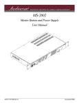
User Instructions
US-2002
Intercom User Station
02
20
US
ten
l
c
Mi
t
se
ad
He
el
n
Pa
c
Mi
All
PA
Kil
Lis
ll
Ca
ten
Lis
ll
Ca
lk
Ta
lk
Ta
lk
Ta
®
e
um
l
Vo
Mic
9350-7748-000 Rev C
09/2009
PROPRIETARY NOTICE
SHIPPING TO THE MANUFACTURER
The product information and design disclosed herein were originated by
and are the property of Bosch Security Systems, Inc. Bosch reserves all
patent, proprietary design, manufacturing, reproduction, use and sales
rights thereto, and to any article disclosed therein, except to the extent
rights are expressly granted to others.
All shipments of product should be made via UPS Ground, prepaid (you
may request from Factory Service a different shipment method). Any
shipment upgrades will be paid by the customer. The equipment should
be shipped in the original packing carton. If the original carton is not
available, use any suitable container that is rigid and of adequate size. If
a substitute container is used, the equipment should be wrapped in paper
and surrounded with at least four (4) inches of excelsior or similar shockabsorbing material. All shipments must be sent to the following address
and must include the Proof of Purchase for warranty repair. Upon
completion of any repair the equipment will be returned via United
Parcel Service or specified shipper, collect.
COPYRIGHT NOTICE
Copyright 2009 by Bosch Security Systems, Inc. All rights reserved.
Reproduction, in whole or in part, without prior written permission from
Bosch is prohibited.
WARRANTY NOTICE
See the enclosed warranty card for further details.
CUSTOMER SUPPORT
Technical questions should be directed to:
Customer Service Department
Bosch Security Systems, Inc.
12000 Portland Avenue South
Burnsville, MN 55337 USA
Telephone: 877-863-4169
Fax: 800-323-0498
Factory Service: 800-553-5992
Factory Service Department
Bosch Security Systems, Inc.
8601 East Cornhusker Hwy.
Lincoln, NE 68507 U.S.A.
Attn: Service
FCC STATEMENT
This equipment uses and can radiate radio frequency energy that may
cause interference to radio communications if not installed in accordance
with this manual. The equipment has been tested and found to comply
with the limits of a Class A computing device pursuant to Subpart J, Part
15 of FCC Rules which are designed to provide reasonable protection
against such interference when operated in a commercial environment.
Operation of this equipment in a residential area may cause interference
which the user (at his own expense) will be required to correct.
RETURN SHIPPING INSTRUCTIONS
Customer Service Department
Bosch Security Systems, Inc. (Lincoln, NE)
Telephone: 402-467-5321
Fax: 402-467-3279
Factory Service: 800-553-5992
Please include a note in the box which supplies the company name,
address, phone number, a person to contact regarding the repair, the type
and quantity of equipment, a description of the problem and the serial
number(s).
This product meets Electromagnetic Compatibility
Directive 89/336/EEC.
Table
of
Contents
INTRODUCTION ............................................................................................................................................................................................ 3
What’s New with the US-2002 ....................................................................................................................................................................... 3
Description .................................................................................................................................................................................................... 3
Features ......................................................................................................................................................................................................... 4
Reference Descriptions .................................................................................................................................................................................. 5
INSTALLATION .............................................................................................................................................................................................. 7
Unpacking ..................................................................................................................................................................................................... 7
Configuration Pre-check ............................................................................................................................................................................... 7
Headset Microphone Type Selection Dip Switch .......................................................................................................................................... 9
Mic Kill Send Enable DIP Switch ................................................................................................................................................................. 9
Program Interrupt DIP Switches ................................................................................................................................................................ 10
Monaural or Binaural Operation DIP Switches ......................................................................................................................................... 10
Balanced / Unbalanced Switch (SW2) ......................................................................................................................................................... 11
Direct Program Listen Enable / Disable Jumpers ...................................................................................................................................... 11
Mounting Configurations ............................................................................................................................................................................ 12
Connections ................................................................................................................................................................................................. 13
CENTRAL MASTER STATION VS. REMOTE STATION ...................................................................................................................................... 13
ALL LOCALLY POWERED STATIONS ............................................................................................................................................................ 13
EXTERNAL PROGRAM INPUT AND PA OUTPUT ........................................................................................................................................... 13
ES-4000A EXPANSION STATION CONNECTION (OPTIONAL COMPONENT) ................................................................................................... 13
Cables .......................................................................................................................................................................................................... 13
OPERATION .................................................................................................................................................................................................. 27
Power-Up Check ......................................................................................................................................................................................... 27
Test Tone ..................................................................................................................................................................................................... 27
Sidetone Adjustment .................................................................................................................................................................................... 28
Voice-Activated Microphone Setup ............................................................................................................................................................. 29
Operation ..................................................................................................................................................................................................... 29
NORMAL VS. PROGRAMMING MODE ........................................................................................................................................................... 29
VOLUME ADJUSTMENT ............................................................................................................................................................................... 29
RECEIVING CALLS ...................................................................................................................................................................................... 30
CALLING AN INTERCOM CHANNEL .............................................................................................................................................................. 30
MICROPHONE MUTE DURING TALK ........................................................................................................................................................... 30
ALL TALK ................................................................................................................................................................................................... 30
PUBLIC ADDRESS ....................................................................................................................................................................................... 31
TURNING THE PROGRAM INPUTS ON AND OFF ............................................................................................................................................ 31
USING MIC KILL ........................................................................................................................................................................................ 31
USING VOICE-ACTIVATED MICROPHONE (VOX) ........................................................................................................................................ 32
INCOMING CALL BEEP ON/OFF ................................................................................................................................................................. 32
Specifications ............................................................................................................................................................................................... 33
Quick Reference .......................................................................................................................................................................................... 35
CHAPTER 1
Introduction
Thank you for purchasing the Audiocom US-2002 Intercom User Station. We hope the many design features of this product
will satisfy your intercommunication requirements for many years to come. To get the most out of your new intercom stations,
please take a few moments to look through this booklet before using the US-2002 for the first time.
What’s New with the US-2002
•
•
•
New internal mechanical design in the panel mic to standardize and improve connections.
Updated gooseneck mic plug connection from a pin connector to a stereo plug for easy installation.
The Telex model MCP-90-XX microphone replaces the EGM-12N and EGM-18N microphone.
Description
The US-2002 Intercom User Station is designed for stationary use by personnel who may require selective access to two or
more intercom channels. It can be rack mounted or used as a desktop station. For rack mounting, optional hardware is required.
For desktop use the four rubber feet supplied.
The US-2002 can be used as a simple, multi-channel user station. Typically, in this application, no program sources or public
address output are connected and some advanced features can be disabled: the station simply provides talk, listen and call
capability for a single user. Alternatively, the US-2002 can function as a master station. In this configuration, most or all
advanced features are activated. Also, program inputs and public address output may be connected. This configuration is ideal
for command and control personnel such as directors, supervisors, etc.
The basic US-2002 can communicate with two (2) intercom channels. The number of channels can be increased by connecting
optional ES-4000A Expansion Stations. Each ES-4000A adds four (4) additional channels, and up to four (4) of these
expansion stations can be connected together for a total of eighteen channels.
3
Features
FIGURE 1.
4
US-2002 Reference View (See “Reference Descriptions” on page 5.)
Reference Descriptions
1.
Dynamic-Mic Headset Connector -
Accepts headset with monaural headphones and either balanced or
unbalanced dynamic microphones.
2.
Panel Mic/Electret Mic Headset Connector - Accepts an electret gooseneck microphone, such as the Telex Model
MCP-90-XX. The Model MCP-90 series panel mic connector is a 1/4”
stereo plug, with a threaded shaft for easy installation.
3.
Volume Control -
Adjusts headphone volume only. If an external speaker is used, volume is
adjusted at the speaker.
4.
VOX Trimmers -
Used with the voice-activated microphone feature. Separate trimmers
adjust the voice activation level for the headset and panel microphones.
5.
Headset and Panel Mic keys -
Used to manually activate either the headset or panel microphone,
whichever is being used.
6.
All Talk Key -
Used to talk to all stations that are listening on all channels. This includes
both US-2002 channels and any connected ES-4000A Expansion
Stations.
7.
PA Key -
This key is used to talk over the public address system if a US-2002 is
connected to a public address system, .
8.
Mic Kill Key -
Used to turn off the microphones on any intercom station on a channel.
Also used to activate the program inputs and the audible beep feature.
9.
Intercom Talk Keys -
Allows momentary or latching (hands-free) operation possible.
10.
Call Keys -
Used to place calls on intercom channels and to indicate calls.
11.
Intercom Listen Keys -
Allows momentary or latching operation possible.
12.
Program Inputs Connector and Trimmers -
Each intercom channel has its own program input and level adjust
trimmers. The program inputs may be turned on or off via the front panel
and they may be set to interrupt during talk, if desired.
13.
Local Power Jack -
Powers the US-2002 from an AC outlet, instead of being powered from
the intercom channels with the use of an optional PA-KP local power
supply.
14.
PA Output -
Connects to a public address system.
15.
Expansion Out Connector -
Connects to an ES-4000A Expansion Station
16.
Speaker Output Jacks -
A single powered loudspeaker or dual powered loud speakers may be
connected for monaural or binaural listening.
17.
Intercom Channel Connectors and
Audiocom/Clear-Com Selector Switch -
Sets the US-2002 for compatibility with either Audiocom or Clear-Com
channel connector pin outs, channel power requirements, and call
signaling requirements.
5
6
CHAPTER 2
Installation
Unpacking
The package contains the following items.
NOTE:
Contact the shipper or your Audiocom dealer immediately if anything is damaged or missing.
Quantity
Description
1
US-2002 Intercom Station
1
Warranty and Registration Card
1
User Manual
4
Rubber feet for desktop use of the US-2002
1
Termination plug for special applications (Figure 13 on page 24)
Configuration Pre-check
Before connecting the US-2002 ensure it is properly configured for your intended usage. Figure 2 on page 8 shows the
configuration jumpers and switches locations.
To access internal switches and jumpers, do the following:
1.
Remove one (1) screw from the top cover.
2.
Remove three (3) screws from each side.
NOTE: Switch SW2 can be accessed through the back panel. If you change any switch settings while the US-2002 is
operating, you must perform a reset: either cycle power off then on, or simultaneously press the All Talk and
Listen 1 keys, then release them. The sidetone controls are adjusted after power-up and are normally
accessed through the bottom cover.
7
FIGURE 2.
TABLE 1. Configuration
SWITCH NUMBER
Locations of Configuration Jumpers and Switches
Switch Settings
DESCRIPTION
SETTINGS
DEFAULT SETTINGS
DIP Switch SW1 (Internal)
SW1-1
Headset microphone type
On: Unbalanced
Off: Balanced (typical)
Off
SW1-2
Call signal send, channel 1
On: Enabled
Off: Disabled
On
SW1-3
Call signal receive, channel 1
On: Enabled
Off: Disabled
On
SW1-4
Call signal send, channel 2
On: Enabled
Off: Disabled
On
SW1-5
Call signal receive, channel 2
On: Enabled
Off: Disabled
On
SW1-6
Mic Kill signal send
On: Enabled
Off: Disabled
Off
SW1-7
Program 2 interrupt
On: Interrupt during talk
Off: No Interrupt
Off
SW1-8
Program 1 interrupt
On: Interrupt during talk
Off: No Interrupt
Off
Push-button Switch SW2 (BAL-UNBAL switch on Back Panel)
Audiocom or Clear-Com operation
Out: Audiocom (balanced)
In: Clear-Com Unbalanced.
Out
Dip Switch SW3 (internal)
SW3-1
8
Incoming call beep
On: Disabled
Off: Enabled
Off
TABLE 1. Configuration
SWITCH NUMBER
Switch Settings
DESCRIPTION
SETTINGS
DEFAULT SETTINGS
SW3-2
Listen 1 to speaker 1 only
On: Enabled (Binaural)
Off: Disabled (Monaural)
On
SW3-3
Incoming call beep, speaker 1
On: Enabled (SW3-1 must be
off)
Off: Disabled
Off
SW3-4
Incoming call beep, speaker 2
On: Enabled (SW3-1 must be
off)
Off: Disabled
Off
SW3-5
Listen 2 to right headphone
On: Enabled (Binaural)
Off: Disabled (Monaural)
On
SW3-6
Listen 2 to speaker 2
On: Enabled (Binaural)
Off: Disabled (Monaural)
On
SW3-7
Listen 2 to speaker 1
On: Enabled (Binaural)
Off: Disabled (Monaural)
Off
SW3-8
Listen 1 to left headphone
On: Enabled (Binaural)
Off: Disabled (Monaural)
On
IMPORTANT: Set all to monaural or all to binaural. Do not mix settings.
Headset Microphone Type Selection Dip Switch
SW1-1 applies only to a dynamic-mic headset connected to the dynamic-mic headset jack on the front panel. If the headset
specifications indicate the microphone type is balanced, or if you are unsure, leave this switch in the off (default) position. If
the specifications indicate an unbalanced microphone set SW1-1 to on.
NOTE:
For best results in noisy environments, a noise canceling (directional or carotid) microphone is highly
recommended. This is especially true if you are using the VOX feature.
Mic Kill Send Enable DIP Switch
The US-2002 can generate an inaudible signal that turns off the microphones on all intercom stations on a channel (for stations
that detect this signal). This feature is useful, for example, when an unattended microphone has been left on and is causing
unnecessary noise on a channel. By default, Mic Kill is not enabled.
To activate this feature, do the following:
>
Set SW1-6 to the on position.
9
Program Interrupt DIP Switches
If you plan to use the external program sources with the US-2002, you have a choice of whether or not you want the program
audio to shut off on the intercom channel while you are talking.
By default, program audio does not interrupt during talk. You can change this as follows:
•
•
For channel 1 program interrupt during talk, set SW1-7 to on.
For channel 2 program interrupt during talk, set SW1-8 to on
If call signal receive is enabled (switches SW1-3 and SW1-5), incoming calls are indicated by red-flashing call keys. An
optional beep tone can also be used. Internal switches enable the beep tone. You can then turn the beep tone on or off via the
front panel during normal operation.
To enable the beep tone, do the following:
1.
Verify the call signal receive DIP switches are on (SW1-3 and SW1-5).
2.
For an incoming call beep in a headset, set SW3-1 to off.
3.
For an incoming call beep in speaker 1, set SW3-1 to off and SW3-3 to on.
4.
For an incoming call beep in speaker 2, set SW3-1 to off and SW3-4 to on.
NOTE: The procedure for turn incoming call beep on or off during operation can be found on page 32.
Monaural or Binaural Operation DIP Switches
The US-2002 can be used with a single speaker or monaural headphones (single- or double-sided) for monaural operation. In
this case, all audio signals are combined and sent to the headphones and the Speaker 1 jack on the back panel. The US-2002
can also be used with two speakers for binaural operation. In this case, channel 1 is sent to the Speaker 1 jack and channel 2 is
sent to the Speaker 2 jack. Binaural headphone operation is not supported.
For Monaural operation with headphones or one speaker (factory default):
•
•
•
•
•
Set SW3-2 to off.
Set SW3-5 to on.
Set SW3-6 to off.
Set SW3-7 to on.
Set SW3-8 to on.
For binaural operation with 2 speakers:
•
•
•
•
•
10
Set SW3-2 to on.
Set SW3-5 to off.
Set SW3-6 to on.
Set SW3-7 to off.
Set SW3-8 to off.
Balanced / Unbalanced Switch (SW2)
This switch is set at the factory to the balanced (BAL) position for use with Audiocom intercom channels.
To set the unit to Clear-Com mode, do the following:
>
Set the switch to the unbalanced (UNBAL) position for use with Clear-Com intercom systems.
Direct Program Listen Enable / Disable Jumpers
By default, each US-2002 program input can be heard by all intercom stations that are listening on the corresponding intercom
channel. This includes the US-2002. Program input routing to the intercom channels can be turned on or off via the US-2002
front panel programming. See “External Program Input and PA Output” on page 13. Additionally, all program signals can be
routed directly to the US-2002 speaker or headset. This lets the US-2002 operator hear the program inputs even if they are not
being routed to the intercom channels.
To disable direct program listening in the speaker or headset for one or more program inputs, do the following:
>
Reset the appropriate jumper as shown in Table 2 .
Jumper
Description
J3
Program 1 direct to Headset or Speaker
J6
Program 2 direct to Headset or Speaker
TABLE 2. Direct
Setting for Jumpers
Pins 2 & 3 shorted: Enabled
Pins 1 & 2 shorted: Disabled
Program Listen Enable/Disable Jumpers
11
Mounting Configurations
The US-2002 can be used on a desktop, or it can be rack mounted. For desktop use, install the four (4) rubber feet supplied
with the US-2002. For rack mounting, use optional Audiocom RMK Rack Mount Kits (Figure 3).
NOTE:
You will have to perform the sidetone adjustment (See “Sidetone Adjustment” on page 28) after all components
are connected. However, when the US-2002 is rack mounted, you may not be able to access the sidetone
trimmers. In this case, you can position the US-2002 in the rack and make all required connections. Then, adjust
the sidetone trimmers before installing and tightening all rack mount screws.
FIGURE 3.
12
Audiocom RMK Rack Mount Kits
Connections
Central Master Station vs. Remote Station
The US-2002 can be used in a variety of configurations as a speaker station or as a headset station. Additionally, it can be used
as a central master station or as a remote station. When used as a central master station, the US-2002 is placed in the same
location as the system power supplies, and if an SPS2001 power supply is used, the US-2002 can take advantage of the
SPS2001 built-in speaker for speaker output. When used as a remote station, a separate speaker must be supplied. Figures 4
through 12, starting on page 15, illustrate several configurations for the US-2002 when used as a central or remote headset or
speaker station.
All Locally Powered Stations
Any US-2002 can be locally powered by connecting a PS-KP Local Power Supply. This is shown as an option in Figures 4
through 12. A special case is an intercom system where all stations are powered from local power supplies, with no central
power supply. This is illustrated in Figure 13 on page 24.
External Program Input and PA Output
Connections for external program input and PA output are show in Figure 14 on page 25.
ES-4000A Expansion Station Connection (Optional Component)
REFERENCE: Refer to the ES-4000A User Instruction Manual (P/N 9350-7551-000) for detailed connection information.
Cables
The numbers below correspond to the cable number in the connection drawings on the following pages.
1.
1-channel intercom cable. Sold separately. Use Bosch “ME” cables, below. Or, build per Figure 15 on page 26.
ME-25: 25’ (7.6 m) cable with Male and Female 3-pin XLR connectors.
ME-50: 50’ (15.2 m) cable with Male and Female 3-pin XLR connectors.
ME-100: 100’ (30.4 m) cable with Male and Female 3-pin XLR connectors.
When connecting from a power supply to a TW-7W, keep cables as short as possible. Also, heavier gage
wire is recommended.
2.
2-channel intercom cable. Sold separately. Use Telex “ME/2” cables, below. Or, build per Figure 15 on page 26.
ME-25: 25’ (7.6 m) cable with Male and Female 6-pin XLR connectors.
ME-50: 50’ (15.2 m) cable with Male and Female 6-pin XLR connectors.
ME-100: 100’ (30.4 m) cable with Male and Female 6-pin XLR connectors.
3.
Y adapter cable. Sold separately. Use Bosch CA-23-16. Or, build per Figure 15 on page 26.
4.
3ft. (0.91m) speaker cable with RCA plugs. One (1) supplied with each SPS-2001 SPK-2000.
5.
18” (457 mm) EXP IN/OUT cable, stereo miniplug to stereo miniplug. One (1) supplied with each ES-4000A.
6.
18” (457 mm) channel output cable, 15-pin Male Dsub to 15-pin Male Dsub. One supplied with each ES-4000A.
(Optional component. See ES-4000A User Manual for connection information.)
7.
Shielded patch cable, 9-pin Male Dsub to 9-pin Female Dsub.
NOTE: Available at most electronic stores.
CAUTION:All pins must be connected straight through: do not use a RS232 computer cable.
13
8.
Shielded patch cable, stereo miniplug to stereo miniplug.
NOTE: Available at most electronic stores.
9.
Shielded audio cable. Must have male 3-pin XLR connector at one end for connection to the XP-USPG or XP-4PGM
program inputs. Pin out for program inputs is as follows:
Pin 1: common
Pin 2: + program input
Pin 3: - program input
10.
Shielded audio cable. Must have male 3-pin XLR connector at one end for connection to the XP-USPG PA output.
Pin out for PA output is as follows:
Pin 1: common
Pin 2: + PA output
Pin 3: - PA output
11.
18” (457 mm) channel output cable, 15-pin Male Dsub to 15-pin Female Dsub. One (1) supplied with each
XP-ES4000.
REFERENCE:
14
For more information, see ES-4000A User Manual [P/N 9350-7551-000] for connection information.
FIGURE 4.
US-2002 Monaural Master Speaker Station Configuration with 1 Power Supply.
The configuration, shown in Figure 4, is suitable for a smaller intercom system when you want to operate the US-2002 as a
master speaker station, with one (1) speaker to monitor both intercom channels. In this configuration, the SPS-2001
Combine/Isolate switch is set to the Isolate position. With this setting, the two (2) intercom channels are completely separated.
The amplified speaker in the SPS2001 is used as the speaker output for the US-2002, and the US-2002 dip switches are set to
monaural operation so that both intercom channels are heard in the speaker. The PA-KP local power supply is optional. When
a PA-KP is connected, the US-2002 automatically disconnects from system power (supplied by the SPS2001). When the US2002 is not drawing power from the intercom system, more system power is available for additional belt packs, etc.
NOTE:
For more information about cables, see Figure 15 on page 26.
NOTE:
A BOP-1000 may be used to rack mount 2 TW-7W splitters.
15
FIGURE 5.
US-2002 Binaural Master Speaker Station Configuration with 1 Power Supply.
The configuration, shown in Figure 5, is suitable for smaller intercom systems when you want to operate the US-2002 as a
master speaker station, with a separate speaker for each intercom channel. Make sure the US-2002 internal dip switches are set
for binaural speaker operation as described on page 10. Also, set the SPS2001 Combine/Isolate switch to the Isolate position.
With this setting, the two (2) intercom channels are completely separated. The amplified speaker in the SPS2001 is used as the
speaker output for channel 1, and the SPK2000 is used for channel 2. The PA-KP local power supply is optional. When a PAKP is connected, the US-2002 automatically disconnects from system power supplied by the SPS2001. Since the US-2002 is
not drawing power from the intercom system, more system power is available for additional belt packs, etc.
NOTE:
For more information about cables, see Figure 15 on page 26.
NOTE:
A BOP-1000 may be used to rack mount 2 TW-7W splitters.
16
FIGURE 6.
US-2002 Master Headset Station Configuration with 1 Power Supply.
The configuration, shown in Figure 6, is suitable for smaller intercom systems when you want to operate the US-2002 as a
master headset station. In this configuration, the PS2001L Combine/Isolate switch is set to the Isolate position. With this
setting, the 2 intercom channels are completely separated. Typically, a headset is connected to the front panel of the US-2002,
and the US-2002 DIP switches are set to monaural operation (default setting), so both intercom channels are heard in the
monaural headphones (binaural headphone operation is not supported). The PA-KP local power supply is optional. When a
PA-KP is connected, the US-2002 automatically disconnects from system power supplied by the PS2001L. Since the US-2002
is not drawing power from the intercom system, more system power is available for additional belt packs, etc.
NOTE:
A BOP-1000 may be used to rack mount 2 TW-7W splitters.
NOTE:
For further information about cables, see Figure 15 on page 26.
17
FIGURE 7.
US-2002 Monaural Master Speaker Station Configuration with 2 Power Supplies.
The configuration, shown in Figure 7, is suitable for large intercom systems when you want to operate the US-2002 as a
master speaker station, with one (1) speaker to monitor both intercom channels. In this configuration, the SPS-2001 and
PS2001L Combine/Isolate switches are set to the Combine position. With this setting, all intercom stations connected to the
SPS2001 are combined on intercom channel 1 and all intercom stations connected to the PS-2001L are combined on channel
2. The amplified speaker in the SPS-2001 is used as the speaker output for the US-2002 and the US-2002 dip switches are set
for monaural operation (default setting) so that both intercom channels are heard in the speaker. The PA-KP local power
supply is optional. When a PA-KP is connected, the US-2002 automatically disconnects from system power. Since the US2002 is not drawing power from the intercom system, more system power is available for additional belt packs, etc.
NOTE:
For more information about cables, see Figure 15 on page 26.
NOTE:
A BOP-1000 may be used to rack mount 2 TW-7W splitters.
18
FIGURE 8.
US-2002 Binaural Speaker Station Configuration with 2 Power Supplies.
The configuration, shown in Figure 8, is suitable for large intercom system when you want to operate the US-2002 as a master
speaker station, with a separate speaker for each intercom channel. In this configuration, the SPS2001 Combine/Isolate
switches are set to the Combine position. With this setting, all intercom stations connected to the one SPS2001 are combined
on intercom channel 1 and all intercom stations connected to the other SPS2001 are combined on channel 2. The amplified
speaker in each SPS2001 monitors a single intercom channel, and the US-2002 dip switches are set to binaural operation (see
page 10.) The PA-KP local power supply is optional. When a PA-KP is connected, the US-2002 automatically disconnects
from system power. Since the US-2002 is not drawing power from the intercom system, more system power is available for
additional belt packs, etc.
NOTE:
For more information about cables, see Figure 15 on page 26.
NOTE:
A BOP-1000 may be used to rack mount 2 TW-7W splitters.
19
FIGURE 9.
US-2002 Headset Station Configuration with 2 Power Supplies.
The configuration, shown in Figure 9, the PS2001L Combine/Isolate switches are set to the Combine position. With this
setting all intercom stations connected to the one (1) PS2001L are combined on intercom channel 1 and all intercom stations
connected to the other PS2001L are combined on channel 2. Typically, a headset is connected to the front panel of the US2002, and the US-2002 dip switches are set to monaural operation (default setting) so that both intercom channels are heard in
the monaural headphones (binaural headphone operation is not supported). The PA-KP local power supply is optional. When a
PA-KP is connected, the US-2002 automatically disconnects from system power. Since the US-2002 is not drawing power
from the intercom system, more system power is available for additional belt packs, etc.
20
NOTE: For further
information about
cables, see
Figure 15 on
page 26.
FIGURE 10.
Typical Remote Headset Station.
The configuration, shown in Figure 10, the US-2002 is not located near the system power supplies (SPS2001, PS2001L, etc.).
The PA-KP local power supply is optional and can be used to power a single intercom station. When a PA-KP is connected to
the US-2002, the US-2002 automatically disconnects from system power. This allows more system power for belt packs and
other intercom stations. Also, when the US-2002 is powered by a PA-KP, it can be operated over a greater distance as a remote
station.
21
NOTE: For further
information about
cables, see
Figure 15 on
page 26.
FIGURE 11.
Typical Remote Monaural Speaker Station.
The configuration, shown in Figure 11, is similar to the one on the previous page, except a Telex MCP-90-XX microphone and
a SPK-2000 speaker are used instead of a headset. Make sure the intercom DIP switches are set for monaural speaker
operation (default setting) as described in “Monaural or Binaural Operation DIP Switches” on page 10. A PA-KP local power
supply is required for the SPK-2000, but is optional for the US-2002. When a PA-KP is connected to the US-2002, the
US-2002 automatically disconnects from system power. This allows more system power for belt packs and other intercom
stations. Also, when the US-2002 is powered by a PA-KP, it can be operated over a greater distance as a remote station.
22
FIGURE 12.
Typical Remote Binaural Speaker Station.
The configuration, shown in Figure 6, is similar to Figure 10, “Typical Remote Headset Station.,” on page 21, except that each
channel is heard in a separate speaker. Make sure the internal DIP switches are set for binaural speaker operation as described
on “Monaural or Binaural Operation DIP Switches” on page 10. As in the previous example, a PA-KP local power supply is
required for each SPK2000 speaker, but is optional for the US-2002.
NOTE:
For more information about cables, see Figure 15 on page 26.
23
FIGURE 13.
An example of all locally powered US-2002 intercom stations.
The configuration, shown in Figure 13, shows all the components are locally powered using PA-KP local power supplies.
Note, the use of one (1) termination plug in each intercom channel. (One (1) termination plug is supplied with each US-2002.)
Only one (1) termination plug should be installed per channel. Typically, they are installed at the first intercom station in the
chain. If 2 terminations are installed in a channel, the sound quality and volume level is noticeably reduced. The advantage of
locally powered stations is that they can be operated over a greater distance than is possible when using a system power
supply.
IMPORTANT:
NOTE:
24
If a system power supply (SPS2001, PS2001L, etc.) is ever connected anywhere in a channel, the
termination plug should be removed from that channel, because the system power supply already has a
built-in termination.
For further information about cables, see Figure 15 on page 26
FIGURE 14.
External Audio Input and PA Output.
The configuration, shown in Figure 14, connects two (2) audio sources to the Program Inputs connector: one (1) for each
channel. Audio sources can be directly connected with a user-supplied DB9M connector. (Refer to the program input
connector specifications, located on page 13, for connector pin-out.) However, a more convenient method is to use an XPUSPG Breakout Panel as shown. The XP-USPG lets you use standard, 3-pin XLR audio cables to connect audio sources. The
XP-USPG also interfaces the PA jack of the US-2002 to a standard, 3-pin XLR audio cable.
NOTE:
The XP-USPG Breakout Panel can be rack mounted using a BOP-1000 Rack Mount Plate.
25
FIGURE 15.
26
Audiocom Intercom Cables
CHAPTER 3
Operation
Power-Up Check
When power is first applied to the US-2002, it performs a power-up reset, in which the front panel indicators cycles through all
of the possible colors and then turn off. This verifies the general operation of the intercom station and indicators. The US-2002
also reads the settings of all DIP switches at this time and configures itself accordingly.
To perform a power-up check, do the following:
1.
Plug in any PA-KP local power supplies being used.
2.
Turn on any system power supplies being used.
Test Tone
The US-2002 can generate a test tone, which is used to verify intercom channel operation after installation or to locate a
malfunction. This test tone is also used for the sidetone adjustment, see “Sidetone Adjustment” on page 28.
To use the test tone, do the following:
1.
Simultaneously press the All Talk and PA keys to activate the test tone.
2.
Tap the Call key for the channel you want to test (can be either US-2002 channel or an ES-4000A channel).
3.
Verify the test tone can be heard at all intercom stations on the channel.
4.
Replace any defective cables or intercom stations where the test tone is being lost.
5.
Tap the same Call key to stop the test signal on that channel.
6.
Press any key, except a Call key, to turn off the test tone.
27
Sidetone Adjustment
The US-2002 uses full-duplex audio, the same as a conventional telephone line, in which the talk and listen audio are sent and
received on the same line. Thus, when you talk on a channel, you also hear your own voice back in the speaker or headphones.
This is called sidetone.
If you are using the US-2002 with a microphone and speaker, sidetone could cause unwanted feedback, since the microphone
may pick up your returned voice audio and re-amplify it. This could also happen if you are using a headset where the ear
cushions do not completely cover the ears. In either case, you should minimize the amount of sidetone.
NOTE:
If you are using headphone that completely enclose the ears, you may want a certain amount of your own voice
level heard to overcome the muffled sensation when talking.
To adjust sidetone using a speaker and microphone, or open-ear style headphones, do the following:
1.
Simultaneously press the ALL Talk and PA keys to activate the test tone.
2.
Tap the channel 1 call key to send the test tone on channel 1.
3.
If you are using a headset, adjust the volume control at the US-2002 until you hear the test tone.
OR
If you are using a speaker, adjust the volume control at the speaker.
4.
Using a small flathead screwdriver, adjust the channel 1 sidetone through the access hole in the bottom of the
US-2002 (Figure 16 on page 28) to minimize the tone volume.
5.
Tap the channel 1 call key to turn off the test tone on channel 1 when finished.
6.
Tap the channel 2 call key, and repeat the steps 3 - 5 for the channel 2 sidetone.
7.
Tap any other key, except a call key, to turn off the test tone when finished.
To adjust sidetone using headphones that completely enclose the ears, do the following:
1.
Tap the Headset key to turn the headset microphone on.
2.
Tap the channel 1 Talk key to turn it on.
3.
While speaking into the microphone, use a small flat-bladed screwdriver to adjust the channel 1 sidetone so you
hear your voice at an acceptable level in the headphones.
4.
Tap the channel 1 Talk key to turn it off when finished.
5.
Tap the channel 2 Talk key to turn it on, and adjust the channel 2 sidetone as for channel 1.
6.
Tap the channel 2 Talk key to turn it off when finished.
FIGURE 16.
28
US-2002 Bottom View
Voice-Activated Microphone Setup
If you are going to use VOX (Voice Operated Switching), you must adjust the vox level for proper operation. If the vox level
is too low, room noise activates the microphone. If the vox level is too high, the microphone does not activate when you begin
talking.
To check and set the VOX level, do the following:
1.
If you are using a headset, tap the headset key twice to turn on headset VOX.
OR
If you are using a panel microphone, tap the panel mic key twice to turn on panel mic vox.
The indicator for the key you tap lights orange when the microphone is off and blinks or turns green when sound is
picked up by the microphone.
2.
Position the microphone at its normal operating location.
NOTE: If you are using a headset, put the headset on and position the microphone close to your mouth.
3.
Ensure background noise is at a normal operating level. Do not speak into the microphone.
4.
Turn the vox trimmer clockwise until the headset or panel mic indicator begins to blinks green (mic activating).
5.
Turn the trimmer slowly counter-clockwise until the panel mic indicator shows steady orange (mic off).
NOTE: If you are wearing a headset, make sure that breathing and movement do not cause the panel mic indicator to
blinks green. If they do, adjust the vox control slightly more in the counter-clockwise direction to eliminate
this.
6.
Speak into the microphone in a normal voice to verify the headset indicator immediately turns green when you talk.
If it does not, move the microphone closer to your mouth.
NOTE: If you are unable to get satisfactory results, it may be the microphone does not have the directional
characteristics required for the noise level in the room. A directional microphone is recommended when
using vox. Omnidirectional microphones may not produce good results.
Operation
NOTE:
A quick-reference to the following operating features can be found on the inside of the back cover (see “Quick
Reference” on page 35).
Normal vs. Programming Mode
The US-2002 has two (2) operating modes:
normal operating mode– the Mic Kill indicator is not lit.
programming mode– the Mic Kill indicator is continuously lit.
To return the US-2002 to normal operation if it has been left in programming mode, do the following:
> Tap the Mic Kill key.
Volume Adjustment
•
If you are using a headset, adjust the intercom listen level with the volume control on the front panel of the US2002.
•
If you are using a speaker, adjust the intercom listen level with the volume control on the speaker.
29
Receiving Calls
When there is an incoming call signal on a channel, the call indicator for that channel blinks red. There is a beep tone if the
beep feature has been activated (see “Incoming Call Beep On/Off” on page 32).
To receive a call, do the following:
1.
If you are using a dynamic-mic headset, tap the headset key to turn the mic on
OR
If you are using a panel-mounted microphone or an electret-mic headset, tap the panel mic key to turn the mic on.
NOTE: You can also use the voice-activated microphone (VOX) feature (See page 32).
2.
Turn on the talk and listen key for the calling channel.
3.
Begin your conversation.
4.
Turn the keys off when finished.
NOTE: When you tap the headset key, or the panel mic key, or an any talk or listen key, it locks in the on position.
You may then tap the key again to turn it off. For momentary activation, press and hold the key. It will
remain on as long as you hold it and turns off when you release it.
Calling an Intercom Channel
To call an intercom channel, do the following:
1.
Press and hold the call key for the channel you want to call
An inaudible call signal is sent and the listen key and indicator for that channel automatically turns on in preparation
to receive a verbal response.
2.
Release the Call key when you hear a response.
3.
If you are using manual microphone activation, verify the microphone is on.
•
•
For a dynamic mic headset, tap the headset key to turn it on;
For a panel-mounted microphone or electret headset, tap the panel mic key to turn it on.
4.
Turn on the Talk key for the channel you called to begin your conversation.
5.
Turn off your Talk and Listen keys to end the conversation.
Microphone Mute During Talk
You can mute the microphone while talking.
To mute the microphone, do the following:
1.
Tap either the headset key or the panel mic key.
The microphone mutes.
2.
Tap the key again to turn the microphone back on. (If you are using Vox, tap the key twice to reactivate vox.)
All Talk
You can talk to all intercom stations that currently have their listen keys activated. This applies to both channels of the US2002 as well as all talk channels of any connected ES-4000A Expansion Stations.
To use All Talk, do the following:
1.
If you are using manual microphone activation, verify the proper microphone switch is turned on (either headset or
panel mic).
2.
Press and hold the All Talk key while talking.
3.
Release the key when finished.
NOTE: To insure the All Talk key is never accidentally left in the on position, it does not latch.
30
Public Address
If the PA (Public Address) output on the back panel of the US-2002 is connected to a public address system., you can talk on
the public address system.
To use the PA system, do the following:
1.
If you are using manual microphone activation, verify the proper microphone switch is turned on (either headset or
panel mic).
2.
Press and hold the PA key while talking.
3.
Release the key when finished.
NOTE: To insure that the PA key is never accidently left in the on position, it does not have latching operation.
Turning the Program Inputs on and off
To turn the program inputs on and off, do the following:
1.
Verify the program inputs have been connected at the back panel.
2.
Verify the program sources are on.
3.
Press and hold the Mic Kill key for two (2) seconds, then release it.
The Mic Kill indicator glows green to indicate the US-2002 is in programming mode.
4.
Tap either talk key to turn the program input for that channel on or off.
NOTE: The current status of the program inputs is indicated by the talk keys. If the channel 1 talk key is lit, the
program 1 input is currently activated to channel 1; if channel 2 talk is lit, program 2 is activated to channel
2.
5.
When the program inputs are configured as desired, tap the Mic Kill key to exit programming mode and return to
normal operation.
6.
Adjust program 1 and 2 levels via the trimmers on the back panel of the US-2002.
Using Mic Kill
If the Mic Kill feature has been enabled (“Mic Kill Send Enable DIP Switch” on page 9) you can use it to deactivate all talk
keys on a single channel or on all channels. This feature is useful when a remote talk key has been left on and is causing
unwanted noise on a channel.
To use Mic Kill, do the following:
1.
Tap the Mic Kill key.
It flashes green.
2.
Tap the Talk or Listen key for a channel to turn off all talk keys on that channel.
OR
Tap the All Talk key to turn off all talk keys.
The key you tap turns green and the Mic Kill signal is sent.
3.
Tap Mic Kill to exit.
31
Using Voice-Activated Microphone (VOX)
If you use VOX, you do not have to insure that the microphone key is turned on whenever you want to talk.
To activate VOX, do the following:
1.
Verify the headset and panel mic key are off.
2.
If you are using a headset, tap the headset key twice to turn on headset vox.
OR
If you are using a panel microphone, tap the panel mic key twice to turn on panel mic vox.
Whichever key you tap lights orange when the microphone is off and blinks or turns green when the microphone turns
on.
NOTE: The VOX level may require adjustment, see Figure , “Voice-Activated Microphone Setup,” on page 29.
Incoming Call Beep On/Off
Normally, incoming calls are indicated by red-flashing call keys.
To turn the incoming call beep on and off, do the following:
32
1.
Verify call beep has been activated via internal switches.
2.
Press and hold the Mic Kill key for about two (2) seconds, then release it.
The Mic Kill key lights green to indicate the intercom station is in programming mode.
3.
Tap either call key on the US-2002 to turn the beep feature on or off.
4.
Tap the Mic Kill key to return to normal operation.
Specifications
General
Power Requirements:
Phantom Power: 24VDC nominal (12 to 30 VDC),
65 to 150mA
Local Power: 12 to 15VDC, 65 to 150mA
Dimensions:
1.75” (44.5mm) high x 8.25” (209.5mm) wide x
10.31” 261.9mm deep
Weight:
Approximately 2lb. (0.9kg)
Environmental Requirements:
Storage: -20°C to 80°C; 0% to 95% humidity,
non-condensing
Operating: -15°C to 60°C; 0% to 95% humidity,
non-condensing
Dynamic-mic Headset
Microphone:
50 to 200 Ohm, dynamic (balanced or unbalanced)
Headphones:
150 to 600 Ohm, monaural
Connector Type: XLR-4M
Pin 1 - Mic low
Pin 2 - Mic high
Pin 3 - Headphone low
Pin 4 - Headphone high
Panel Microphone or Electret-mic Headset
Microphone:
5k Ohm, electret (-57dB)
Headphones:
150 to 600 Ohm, monaural
Connector Type:
IKP12 (MCP-90 series, stereo plug connector)
Program Input
Input Level:
100mB maximum
Voltage Gain:
25 ±3dB
Output Level:
1.0 VRMS nominal, 2.3 VRMS maximum
Input Impedance:
75k Ohm
Common Mode Rejection:
Greater than 50dB
Connector Type: DB9F
Pin 1 - Ground
Pin 2 - Program 1 input low
Pin 3 - Program 2 input low
Pin 4 - NC
Pin 5 - NC
Pin 6 - Program 1 input high
Pin 7 - Program 2 input high
Pin 8 - NC
Pin 9 - NC
Intercom Channels, Balanced Mode
(SW2 set to BAL position)
Output Level:
1 VRMS nominal
Input Impedance:
300 Ohms
Bridging Impedance:
greater than 10,000 Ohms
Sidetone:
-40dB, 35dB adjustable range
Call Signaling:
Send: 20kHz ±300Hz, 0.5VRMS ±10%
Receive: 20kHz ±800Hz, 100mVRMS
Mic-Kill Frequency
Send: 24kHz ±100Hz, 0.5VRMS ±10%
Detect: 24kHz ±800Hz, 100mVRMS
Noise Contribution
less than -70dB
Common Mode Rejection Ratio:
greater than 50dB
Connector Type: one XLR-3M and XLR-3F pair,
wired in parallel, for each channel.
Pin 1 - Common
Pin 2 - Intercom audio low and +24VDC input
Pin 3 - Intercom audio high and +24VDC input
Intercom Channel, Unbalanced Mode
(SW2 set to UNBAL position)
Output Level:
1VRMS ±10%
Input Impedance:
150 Ohms
Bridging Impedance:
greater than 10,000 Ohms
Call Signaling:
Send: 11 ±3VDC
Receive: 4VDC minimum
33
Connector Type: one XLR-3M and XLR-3F pair,
wired in parallel, for each channel.
Pin 1 - Common
Pin 2 - +24VDC input
Pin 3 - Intercom audio high
PA Output
Output Level
235mVRMS
Connector Type: 1/8-inch Stereo Phone Jack
Tip - PA output high
Ring - Not used
Sleeve - Common
Speaker Output
Output Level:
0dB nominal (1.0 VRMS)
Output Impedance:
1000 Ohms nominal
Frequency Response:
200Hz to 8kHz +1/-3dB
Connector Type: RCA Phono Jack
Tip: Speaker output high
Sleeve: Common
Expansion Input/Output
Type: 2.0mm stereo phone jack
Tip: Talk output
Ring: Listen input
Sleeve: Common
External Power
Type: 2.0mm power jack
Internal pin: positive (+)
External shell: negative (-)
Headphone Amplifier
Voltage Gain:
30 ±3dB
Maximum Output:
250 mW ±10% into 150 Ohms, 65mW ±10% into
600 Ohms
Frequency Response:
200Hz to 8kHz +1/-3dB
Incoming Call Beep Tone:
2kHz, at the headphones
Total Harmonic Distortion:
Less than 0.2% at 200mW
Sidetone:
18 ±2dB, adjustable
34
Panel Microphone Amplifier
Voltage Gains:
Mic to CHN; 25 ±3dB, before limiting
Mic to Headphone; adjustable, 45dB ±10%
maximum, into 150 Ohms
Mic to PA; 15 ±3dB, 235mVRMS ±10%
Frequency Response:
200Hz to 8kHz +1/-3dB
Total Harmonic Distortion:
Less than 0.2% at CHN output
VOX Range
-75 to -30dB, -60dB factory set
Quick Reference
TABLE 3. Quick
Reference
Reset US-2002
Press All Talk and Listen 1
Reset ES-4000A
Press All Talk and Listen 5
Test signal on
Press All Talk and PA, then tap Call
Test signal off
Tap Call, then tap any other key
Mic latched on
Tap Headset or Panel Mic
Mic latched off
Tap Headset or Panel Mic
Mic momentary on
Hold Headset or Panel Mic
Mic momentary off
Release Headset or Panel Mic
VOX mode on
Tap twice: Headset or Panel Mic key
VOX mode off
Tap Headset or Panel Mic
All Talk on
Hold All Talk when Headset or Panel Mic is lit
All Talk off
Release All Talk
Public Address
Hold PA when Headset or Panel Mic is lit (PA key is green)
Mic Kill, one channel
Tap Mic Kill, then tap Talk or Listen (Mic Kill key blinks green, and the Talk and Listen keys
are green. Tap Mic Kill to exit.)
Mic Kill, all channels
Tap Mic Kill, than tap All Talk (Mic Kill key blinks green, and all Talk and Listen keys are
green.) Tap Mic Kill to exit.
Program on
Hold Mic Kill, then tap channel’s Talk key (key is green). Tap Mic Kill to exit.
Program off
Hold Mic Kill, then tap channel’s Talk key. Tap Mic Kill to exit
Audible call alert on
Hold Mic Kill, then tap either Call (all Call keys are red). Tap Mic Kill to exit.
Audible call alert off
Hold Mic Kill, then tap either Call. Tap Mic Kill to exit
Turn Mic Kill key off
Tap Mic Kill
Talk latched on
Tap Talk (key is green)
Talk latched off
Tap Talk.
Talk momentary on
Hold Talk
Talk momentary off
Release Talk
Call Signal on
Hold Call
Call signal off
Release Call
Receive Call Signal
Key blinks red.
Listen latched on
Tap Listen (key is green)
Listen latched off
Tap Listen
Listen momentary on
Hold Listen.
35