1
Programmer Manual
AM700
Audio Measurement Set
070-9001-01
This document applies to firmware version 1.04
and above.
Copyright Tektronix, Inc. All rights reserved. Licensed software products are owned by Tektronix
or its suppliers and are protected by United States copyright laws and international treaty provisions.
Use, duplication, or disclosure by the Government is subject to restrictions as set forth in
subparagraph (c)(1)(ii) of the Rights in Technical Data and Computer Software clause at DFARS
252.227-7013, or subparagraphs (c)(1) and (2) of the Commercial Computer Software – Restricted
Rights clause at FAR 52.227-19, as applicable.
Tektronix products are covered by U.S. and foreign patents, issued and pending. Information in this
publication supercedes that in all previously published material. Specifications and price change
privileges reserved.
Printed in the U.S.A.
Tektronix, Inc., P.O. Box 1000, Wilsonville, OR 97070–1000
TEKTRONIX and TEK are registered trademarks of Tektronix, Inc.
Table of Contents
Preface . . . . . . . . . . . . . . . . . . . . . . . . . . . . . . . . . . . . . . . . . . . . . . . .
Manual Content . . . . . . . . . . . . . . . . . . . . . . . . . . . . . . . . . . . . . . . . . . . .
xxi
xxi
Getting Started
GPIB and RS-232C Remote Operation . . . . . . . . . . . . . . . . . . . . . . . . . .
Accessories for Remote Control . . . . . . . . . . . . . . . . . . . . . . . . . . . .
Control Protocol . . . . . . . . . . . . . . . . . . . . . . . . . . . . . . . . . . . . . . . . .
Control Ports . . . . . . . . . . . . . . . . . . . . . . . . . . . . . . . . . . . . . . . . . . .
GPIB Interface Information . . . . . . . . . . . . . . . . . . . . . . . . . . . . . . . .
IEEE 488.2 Commands . . . . . . . . . . . . . . . . . . . . . . . . . . . . . . . . . . .
RS-232C Interface Information . . . . . . . . . . . . . . . . . . . . . . . . . . . . .
Rear Panel I/O Connectors . . . . . . . . . . . . . . . . . . . . . . . . . . . . . . . . . . . .
GPIB Connector . . . . . . . . . . . . . . . . . . . . . . . . . . . . . . . . . . . . . . . . .
COM1 and COM2 Serial Ports . . . . . . . . . . . . . . . . . . . . . . . . . . . . .
REMOTE Connector . . . . . . . . . . . . . . . . . . . . . . . . . . . . . . . . . . . . .
System Communication . . . . . . . . . . . . . . . . . . . . . . . . . . . . . . . . . . . . . .
Connecting Printers . . . . . . . . . . . . . . . . . . . . . . . . . . . . . . . . . . . . . . . . .
Connecting an EPSON LQ Printer . . . . . . . . . . . . . . . . . . . . . . . . . .
Connecting an Apple LaserWriter . . . . . . . . . . . . . . . . . . . . . . . . . . .
Connecting an HP LaserJet, DeskJet, or ThinkJet . . . . . . . . . . . . . . .
Making Your Own LaserJet Cable . . . . . . . . . . . . . . . . . . . . . . . . . . .
Connecting an ASCII Printer . . . . . . . . . . . . . . . . . . . . . . . . . . . . . . .
Hardcopy Output . . . . . . . . . . . . . . . . . . . . . . . . . . . . . . . . . . . . . . . . . . .
Copy Formats . . . . . . . . . . . . . . . . . . . . . . . . . . . . . . . . . . . . . . . . . . .
Copy Destination . . . . . . . . . . . . . . . . . . . . . . . . . . . . . . . . . . . . . . . .
Copy Styles . . . . . . . . . . . . . . . . . . . . . . . . . . . . . . . . . . . . . . . . . . . .
AM700 SCPI Control Model . . . . . . . . . . . . . . . . . . . . . . . . . . . . . . . . . .
AM700 Analog Signal Path . . . . . . . . . . . . . . . . . . . . . . . . . . . . . . . . . . .
AM700 Signal Selection and Routing . . . . . . . . . . . . . . . . . . . . . . . . . . .
AM700 Audio Measurement Set Programmer Manual
1–1
1–1
1–1
1–2
1–2
1–3
1–5
1–7
1–7
1–8
1–8
1–10
1–11
1–11
1–12
1–13
1–13
1–14
1–14
1–16
1–16
1–17
1–17
1–18
1–20
i
Table of Contents
ROUTe Subsystem . . . . . . . . . . . . . . . . . . . . . . . . . . . . . . . . . . . . . . .
INPut Subsystem . . . . . . . . . . . . . . . . . . . . . . . . . . . . . . . . . . . . . . . .
SENSe Subsystem . . . . . . . . . . . . . . . . . . . . . . . . . . . . . . . . . . . . . . .
CSTReam Subsystem . . . . . . . . . . . . . . . . . . . . . . . . . . . . . . . . . . . . .
CALCulate Subsystem . . . . . . . . . . . . . . . . . . . . . . . . . . . . . . . . . . . .
AMEasure Subsystem . . . . . . . . . . . . . . . . . . . . . . . . . . . . . . . . . . . .
TRACe Subsystem . . . . . . . . . . . . . . . . . . . . . . . . . . . . . . . . . . . . . . .
DISPlay Subsystem . . . . . . . . . . . . . . . . . . . . . . . . . . . . . . . . . . . . . .
SYSTem Subsystem . . . . . . . . . . . . . . . . . . . . . . . . . . . . . . . . . . . . . .
STATus Subsystem . . . . . . . . . . . . . . . . . . . . . . . . . . . . . . . . . . . . . . .
INSTrument Subsystem . . . . . . . . . . . . . . . . . . . . . . . . . . . . . . . . . . .
MMEMory Subsystem . . . . . . . . . . . . . . . . . . . . . . . . . . . . . . . . . . . .
PROGram Subsystem . . . . . . . . . . . . . . . . . . . . . . . . . . . . . . . . . . . .
GCONtrol Subsystem . . . . . . . . . . . . . . . . . . . . . . . . . . . . . . . . . . . .
1–21
1–22
1–24
1–25
1–25
1–28
1–28
1–29
1–29
1–30
1–30
1–31
1–33
1–33
SCPI Conformance Information
SCPI Command Subsystems Implemented in the AM700 . . . . . . . . . . .
SCPI Background Information . . . . . . . . . . . . . . . . . . . . . . . . . . . . . . . . .
SCPI Goal . . . . . . . . . . . . . . . . . . . . . . . . . . . . . . . . . . . . . . . . . . . . .
SCPI Compliance Criteria . . . . . . . . . . . . . . . . . . . . . . . . . . . . . . . . .
SCPI References . . . . . . . . . . . . . . . . . . . . . . . . . . . . . . . . . . . . . . . .
2–1
2–3
2–3
2–3
2–4
AM700 SCPI Commands
IEEE Mandated Commands . . . . . . . . . . . . . . . . . . . . . . . . . . . . . . . . . . .
Required Commands . . . . . . . . . . . . . . . . . . . . . . . . . . . . . . . . . . . . . . . .
Optional Commands . . . . . . . . . . . . . . . . . . . . . . . . . . . . . . . . . . . . . . . . .
Command Notation in this Manual . . . . . . . . . . . . . . . . . . . . . . . . . . . . .
AMEasure Subsystem . . . . . . . . . . . . . . . . . . . . . . . . . . . . . . . . . . . . . . .
AMEasure Subsystem (FFT) . . . . . . . . . . . . . . . . . . . . . . . . . . . . . . . . . .
AMEasure Subsystem (Digital Interface Tester) . . . . . . . . . . . . . . . . . . .
AMEasure Subsystem (Audio Monitor) . . . . . . . . . . . . . . . . . . . . . . . . .
CALCulate Subsystem (Average) . . . . . . . . . . . . . . . . . . . . . . . . . . . . . .
CALCulate Subsystem (FFT Analyzer) . . . . . . . . . . . . . . . . . . . . . . . . . .
CALibration Subsystem . . . . . . . . . . . . . . . . . . . . . . . . . . . . . . . . . . . . . .
CMODe Subsystem (Audio Analyzer) . . . . . . . . . . . . . . . . . . . . . . . . . . .
ii
3–1
3–2
3–2
3–4
3–7
3–27
3–30
3–32
3–33
3–35
3–39
3–41
AM700 Audio Measurement Set Programmer Manual
Table of Contents
CMODe Subsystem (FFT / MTONe Analyzer) . . . . . . . . . . . . . . . . . . . .
CMODe Subsystem (SOUNd and DAUDio) . . . . . . . . . . . . . . . . . . . . . .
CMODe Subsystem (Trigger) . . . . . . . . . . . . . . . . . . . . . . . . . . . . . . . . .
CSTReam Subsystem . . . . . . . . . . . . . . . . . . . . . . . . . . . . . . . . . . . . . . . .
DISPlay Subsystem . . . . . . . . . . . . . . . . . . . . . . . . . . . . . . . . . . . . . . . . .
FORMat Subsystem . . . . . . . . . . . . . . . . . . . . . . . . . . . . . . . . . . . . . . . . .
GCONtrol Subsystem . . . . . . . . . . . . . . . . . . . . . . . . . . . . . . . . . . . . . . . .
HCOPy Subsystem . . . . . . . . . . . . . . . . . . . . . . . . . . . . . . . . . . . . . . . . . .
INPut Subsystem . . . . . . . . . . . . . . . . . . . . . . . . . . . . . . . . . . . . . . . . . . .
INSTrument Subsystem . . . . . . . . . . . . . . . . . . . . . . . . . . . . . . . . . . . . . .
MMEMory Subsystem . . . . . . . . . . . . . . . . . . . . . . . . . . . . . . . . . . . . . . .
Console File . . . . . . . . . . . . . . . . . . . . . . . . . . . . . . . . . . . . . . . . . . . .
AM700 File Structure . . . . . . . . . . . . . . . . . . . . . . . . . . . . . . . . . . . .
File Names . . . . . . . . . . . . . . . . . . . . . . . . . . . . . . . . . . . . . . . . . . . . .
File Name Capacity . . . . . . . . . . . . . . . . . . . . . . . . . . . . . . . . . . . . . .
OUTPut Subsystem . . . . . . . . . . . . . . . . . . . . . . . . . . . . . . . . . . . . . . . . .
PROGram Subsystem . . . . . . . . . . . . . . . . . . . . . . . . . . . . . . . . . . . . . . . .
ROUTe Subsystem . . . . . . . . . . . . . . . . . . . . . . . . . . . . . . . . . . . . . . . . . .
SENSe Subsystem . . . . . . . . . . . . . . . . . . . . . . . . . . . . . . . . . . . . . . . . . .
SOURce:DAUDio Subsystem . . . . . . . . . . . . . . . . . . . . . . . . . . . . . . . . .
SOURce:FOLLow Subsystem . . . . . . . . . . . . . . . . . . . . . . . . . . . . . . . . .
SOURce:FREQuency Subsystem . . . . . . . . . . . . . . . . . . . . . . . . . . . . . . .
SOURce:FUNCtion Subsystem . . . . . . . . . . . . . . . . . . . . . . . . . . . . . . . .
SOURce:LIST Subsystem . . . . . . . . . . . . . . . . . . . . . . . . . . . . . . . . . . . .
SOURce:MTONe Subsystem . . . . . . . . . . . . . . . . . . . . . . . . . . . . . . . . . .
SOURce:STATe Subsystem . . . . . . . . . . . . . . . . . . . . . . . . . . . . . . . . . . .
SOURce:SWEep Subsystem . . . . . . . . . . . . . . . . . . . . . . . . . . . . . . . . . .
SOURce:USER Subsystem . . . . . . . . . . . . . . . . . . . . . . . . . . . . . . . . . . .
SOURce:VOLTage Subsystem . . . . . . . . . . . . . . . . . . . . . . . . . . . . . . . . .
STATus Subsystem . . . . . . . . . . . . . . . . . . . . . . . . . . . . . . . . . . . . . . . . . .
Status Reporting Structures . . . . . . . . . . . . . . . . . . . . . . . . . . . . . . . .
STATus:OPERation:INSTrument Registers . . . . . . . . . . . . . . . . . . . . . . .
Status Operation Instrument Registers . . . . . . . . . . . . . . . . . . . . . . . .
STATus:OPERation:TRIGger Registers . . . . . . . . . . . . . . . . . . . . . . . . .
STATus:OPERation:SYSTem Registers . . . . . . . . . . . . . . . . . . . . . . . . . .
STAT:OPER:SYST Summary . . . . . . . . . . . . . . . . . . . . . . . . . . . . . . . . .
AM700 Audio Measurement Set Programmer Manual
3–45
3–48
3–49
3–51
3–53
3–68
3–69
3–71
3–75
3–77
3–81
3–81
3–82
3–82
3–82
3–89
3–93
3–102
3–104
3–108
3–112
3–113
3–115
3–128
3–131
3–132
3–133
3–136
3–138
3–140
3–140
3–147
3–147
3–150
3–152
3–152
iii
Table of Contents
Status Questionable Registers . . . . . . . . . . . . . . . . . . . . . . . . . . . . . . . . .
Status Questionable Input Registers . . . . . . . . . . . . . . . . . . . . . . . . . . . . .
Status Questionable Input Summary Registers . . . . . . . . . . . . . . . . . . . .
STATus:QUEStionable Registers Conditions . . . . . . . . . . . . . . . . . . . . .
SOURce Summary . . . . . . . . . . . . . . . . . . . . . . . . . . . . . . . . . . . . . . . . . .
INSTrument Conditions . . . . . . . . . . . . . . . . . . . . . . . . . . . . . . . . . . . . . .
User Modifiable Conditions and Events . . . . . . . . . . . . . . . . . . . . . . . . .
Status Questionable Instrument Registers . . . . . . . . . . . . . . . . . . . . . . . .
Status Questionable Source Registers . . . . . . . . . . . . . . . . . . . . . . . . . . .
Status Questionable Source Summary Registers . . . . . . . . . . . . . . . . . . .
SYSTem Subsystem . . . . . . . . . . . . . . . . . . . . . . . . . . . . . . . . . . . . . . . . .
TRACe Subsystem . . . . . . . . . . . . . . . . . . . . . . . . . . . . . . . . . . . . . . . . . .
TRiGger Subsystem . . . . . . . . . . . . . . . . . . . . . . . . . . . . . . . . . . . . . . . . .
UNIT Subsystem . . . . . . . . . . . . . . . . . . . . . . . . . . . . . . . . . . . . . . . . . . .
AM700 Use of the Unit Subsystem . . . . . . . . . . . . . . . . . . . . . . . . . .
3–154
3–156
3–158
3–159
3–160
3–161
3–163
3–165
3–166
3–167
3–168
3–175
3–181
3–182
3–182
Writing a Function . . . . . . . . . . . . . . . . . . . . . . . . . . . . . . . . . . . . . . . . . .
Sample Function Program . . . . . . . . . . . . . . . . . . . . . . . . . . . . . . . . .
Running a Function . . . . . . . . . . . . . . . . . . . . . . . . . . . . . . . . . . . . . .
Timed Functions . . . . . . . . . . . . . . . . . . . . . . . . . . . . . . . . . . . . . . . .
Tcl Programming Changes . . . . . . . . . . . . . . . . . . . . . . . . . . . . . . . . .
4–1
4–1
4–4
4–5
4–6
Examples
Index
iv
AM700 Audio Measurement Set Programmer Manual
Table of Contents
List of Figures
Figure 1–1: AM700 Rear Panel . . . . . . . . . . . . . . . . . . . . . . . . . . . . . . .
1–7
Figure 1–2: GPIB Connector . . . . . . . . . . . . . . . . . . . . . . . . . . . . . . . . .
1–7
Figure 1–3: COM1 and COM2 serial ports . . . . . . . . . . . . . . . . . . . . .
1–8
Figure 1–4: Remote contact-closure connector . . . . . . . . . . . . . . . . . .
1–9
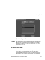
Figure 1–5: Configure system setup communicate menu . . . . . . . . . .
1–11
Figure 1–6: The copy configuration menu . . . . . . . . . . . . . . . . . . . . . .
1–15
Figure 1–7: Hard Copy output file selector . . . . . . . . . . . . . . . . . . . . .
1–17
Figure 1–8: AM700 SCPI systems for measurements . . . . . . . . . . . . .
1–18
Figure 1–9: Analog hardware SCPI system subsystems . . . . . . . . . . .
1–19
Figure 1–10: AM700 signal routing to CSTReam . . . . . . . . . . . . . . . .
1–20
Figure 1–11: FFT CALCulate subsystem block . . . . . . . . . . . . . . . . .
1–26
Figure 1–12: Switching Between FFT and Multitone . . . . . . . . . . . . .
1–27
Figure 1–13: GCONtrol subsystem for the AM700 generator . . . . . .
1–35
Figure 3–1: Status register operation showing a bit transition
event for multitone . . . . . . . . . . . . . . . . . . . . . . . . . . . . . . . . . . . . . .
3–142
Figure 4–1: Sample of a SCPI function . . . . . . . . . . . . . . . . . . . . . . . .
4–3
Table 1–1: IEEE 488.1 interface functions implemented in
the AM700 . . . . . . . . . . . . . . . . . . . . . . . . . . . . . . . . . . . . . . . . . . . .
1–3
Table 1–2: IEEE 488.2 status reporting commands . . . . . . . . . . . . . .
1–3
Table 1–3: Internal operation commands . . . . . . . . . . . . . . . . . . . . . .
1–4
Table 1–4: Synchronization commands . . . . . . . . . . . . . . . . . . . . . . . .
1–5
Table 1–5: Serial port protocol . . . . . . . . . . . . . . . . . . . . . . . . . . . . . . .
1–5
Table 1–6: Remote connector pins . . . . . . . . . . . . . . . . . . . . . . . . . . . .
1–9
List of Tables
Table 1–7: Epson LQ cable connections . . . . . . . . . . . . . . . . . . . . . . .
1–12
Table 1–8: Apple LaserWriter connections . . . . . . . . . . . . . . . . . . . . .
1–13
Table 1–9: HP LaserJet cable connections . . . . . . . . . . . . . . . . . . . . .
1–14
AM700 Audio Measurement Set Programmer Manual
v
Table of Contents
vi
Table 2–1: SCPI subsystems implemented in the AM700 . . . . . . . . .
2–1
Table 2–2: New command subsystems implemented in the AM700 .
2–2
Table 3–1: IEEE mandated commands . . . . . . . . . . . . . . . . . . . . . . . .
3–1
Table 3–2: SCPI required commands . . . . . . . . . . . . . . . . . . . . . . . . .
3–2
Table 3–3: SCPI command syntax symbols . . . . . . . . . . . . . . . . . . . .
3–3
Table 3–4: Summary of STATus:OPERation . . . . . . . . . . . . . . . . . . .
3–144
Table 3–5: STATus:OPERation . . . . . . . . . . . . . . . . . . . . . . . . . . . . . .
3–144
Table 3–6: STATus:OPERation:Instrument . . . . . . . . . . . . . . . . . . . .
3–147
Table 3–7: Trigger conditions used by the FFT application . . . . . . .
3–150
Table 3–8: Trigger conditions used by the Scope application . . . . . .
3–150
Table 3–9: TRIGger subsystem layer-change events . . . . . . . . . . . . .
3–151
Table 3–10: STATus:OPERation . . . . . . . . . . . . . . . . . . . . . . . . . . . . .
3–152
Table 3–11: System conditions . . . . . . . . . . . . . . . . . . . . . . . . . . . . . . .
3–152
Table 3–12: STATus:QUEStionable . . . . . . . . . . . . . . . . . . . . . . . . . . .
3–154
Table 3–13: STATus:QUEStionable:INPut:SUMmary . . . . . . . . . . .
3–156
Table 3–14: STATus:QUEStionable:SOURce:SUMmary . . . . . . . . .
3–160
Table 3–15: INSTrument conditions . . . . . . . . . . . . . . . . . . . . . . . . . .
3–161
Table 3–16: INPut conditions . . . . . . . . . . . . . . . . . . . . . . . . . . . . . . . .
3–161
Table 3–17: User modifiable conditions . . . . . . . . . . . . . . . . . . . . . . .
3–163
Table 3–18: User modifiable events . . . . . . . . . . . . . . . . . . . . . . . . . . .
3–163
AM700 Audio Measurement Set Programmer Manual
Table of Contents
SCPI Command List
ROOT:SUBSystem:SUBSystem:COMMand . . . . . . . . . . . . . . . . . . . . . . . . . . . . . . . . . . . . .
3–4
AMEasure[1–4]:STATe . . . . . . . . . . . . . . . . . . . . . . . . . . . . . . . . . . . . . . . . . . . . . . . . . . . . .
3–7
AMEasure[1–4]:HISTory . . . . . . . . . . . . . . . . . . . . . . . . . . . . . . . . . . . . . . . . . . . . . . . . . . . .
3–7
AMEasure[1–5]:MODE . . . . . . . . . . . . . . . . . . . . . . . . . . . . . . . . . . . . . . . . . . . . . . . . . . . . .
3–8
AMEasure[1–4]:REFerence:CLEar . . . . . . . . . . . . . . . . . . . . . . . . . . . . . . . . . . . . . . . . . . . .
3–8
AMEasure[1–4]:REFerence:FILE[:NAME] . . . . . . . . . . . . . . . . . . . . . . . . . . . . . . . . . . . . .
3–8
AMEasure[1–4]:REFerence:FILE:LOAD . . . . . . . . . . . . . . . . . . . . . . . . . . . . . . . . . . . . . . .
3–8
AMEasure[1–4]:REFerence:FILE:STORe . . . . . . . . . . . . . . . . . . . . . . . . . . . . . . . . . . . . . . .
3–9
AMEasure[1–4]:REFerence:SET . . . . . . . . . . . . . . . . . . . . . . . . . . . . . . . . . . . . . . . . . . . . . .
3–9
AMEasure[1–4]:REFerence:STATe? . . . . . . . . . . . . . . . . . . . . . . . . . . . . . . . . . . . . . . . . . . .
3–9
AMEasure[1–4]:XY:TRACkgen . . . . . . . . . . . . . . . . . . . . . . . . . . . . . . . . . . . . . . . . . . . . . .
3–9
AMEasure[1–4]:XY:X:INPut . . . . . . . . . . . . . . . . . . . . . . . . . . . . . . . . . . . . . . . . . . . . . . . . .
3–10
AMEasure[1–4]:REGulation:COUNt . . . . . . . . . . . . . . . . . . . . . . . . . . . . . . . . . . . . . . . . . .
3–10
AMEasure[1–4]:REGulation:ERRor . . . . . . . . . . . . . . . . . . . . . . . . . . . . . . . . . . . . . . . . . . .
3–10
AMEasure[1–4]:REGulation:FUNCtion . . . . . . . . . . . . . . . . . . . . . . . . . . . . . . . . . . . . . . . .
3–11
AMEasure[1–4]:REGulation:INPut . . . . . . . . . . . . . . . . . . . . . . . . . . . . . . . . . . . . . . . . . . . .
3–11
AMEasure[1–4]:REGulation:TARGet . . . . . . . . . . . . . . . . . . . . . . . . . . . . . . . . . . . . . . . . . .
3–12
AMEasure[1–4]:REGulation:GENerator . . . . . . . . . . . . . . . . . . . . . . . . . . . . . . . . . . . . . . . .
3–12
AMEasure[1–4]:REGulation:FREQuency:LOWer . . . . . . . . . . . . . . . . . . . . . . . . . . . . . . . .
3–12
AMEasure[1–4]:REGulation:FREQuency:MODE . . . . . . . . . . . . . . . . . . . . . . . . . . . . . . . .
3–13
AMEasure[1–4]:REGulation:FREQuency:POINts . . . . . . . . . . . . . . . . . . . . . . . . . . . . . . . .
3–13
AMEasure[1–4]:REGulation:FREQuency:UPPer . . . . . . . . . . . . . . . . . . . . . . . . . . . . . . . . .
3–13
AMEasure[1–4]:REGulation:LEVel:LOWer . . . . . . . . . . . . . . . . . . . . . . . . . . . . . . . . . . . . .
3–14
AMEasure[1–4]:REGulation:LEVel:UPPer . . . . . . . . . . . . . . . . . . . . . . . . . . . . . . . . . . . . . .
3–14
AMEasure:SETTled:CROSstalk:RESolution . . . . . . . . . . . . . . . . . . . . . . . . . . . . . . . . . . . .
3–14
AMEasure:SETTled:CROSstalk:TOLerance . . . . . . . . . . . . . . . . . . . . . . . . . . . . . . . . . . . . .
3–15
AMEasure:SETTled:DELay . . . . . . . . . . . . . . . . . . . . . . . . . . . . . . . . . . . . . . . . . . . . . . . . . .
3–15
AMEasure:SETTled:ENABle . . . . . . . . . . . . . . . . . . . . . . . . . . . . . . . . . . . . . . . . . . . . . . . .
3–15
AM700 Audio Measurement Set Programmer Manual
vii
Table of Contents
viii
AMEasure:SETTled:FREQuency:RESolution . . . . . . . . . . . . . . . . . . . . . . . . . . . . . . . . . . . .
3–16
AMEasure:SETTled:FREQuency:TOLerance . . . . . . . . . . . . . . . . . . . . . . . . . . . . . . . . . . . .
3–16
AMEasure:SETTled:IMD:RESolution . . . . . . . . . . . . . . . . . . . . . . . . . . . . . . . . . . . . . . . . . .
3–16
AMEasure:SETTled:IMD:TOLerance . . . . . . . . . . . . . . . . . . . . . . . . . . . . . . . . . . . . . . . . . .
3–17
AMEasure:SETTled:LDIFference:RESolution . . . . . . . . . . . . . . . . . . . . . . . . . . . . . . . . . . .
3–17
AMEasure:SETTled:LDIFference:TOLerance . . . . . . . . . . . . . . . . . . . . . . . . . . . . . . . . . . .
3–17
AMEasure:SETTled:LEVel:MINimum . . . . . . . . . . . . . . . . . . . . . . . . . . . . . . . . . . . . . . . . .
3–18
AMEasure:SETTled:LEVel:RESolution . . . . . . . . . . . . . . . . . . . . . . . . . . . . . . . . . . . . . . . .
3–18
AMEasure:SETTled:LEVel:TOLerance . . . . . . . . . . . . . . . . . . . . . . . . . . . . . . . . . . . . . . . . .
3–18
AMEasure:SETTled:PDIFference:RESolution . . . . . . . . . . . . . . . . . . . . . . . . . . . . . . . . . . .
3–19
AMEasure:SETTled:PDIFference:TOLerance . . . . . . . . . . . . . . . . . . . . . . . . . . . . . . . . . . .
3–19
AMEasure:SETTled:SEParation:RESolution . . . . . . . . . . . . . . . . . . . . . . . . . . . . . . . . . . . .
3–19
AMEasure:SETTled:SEParation:TOLerance . . . . . . . . . . . . . . . . . . . . . . . . . . . . . . . . . . . . .
3–20
AMEasure:SETTled:THD:RESolution . . . . . . . . . . . . . . . . . . . . . . . . . . . . . . . . . . . . . . . . .
3–20
AMEasure:SETTled:THD:TOLerance . . . . . . . . . . . . . . . . . . . . . . . . . . . . . . . . . . . . . . . . . .
3–20
AMEasure:SETTled:THDN:RESolution . . . . . . . . . . . . . . . . . . . . . . . . . . . . . . . . . . . . . . . .
3–21
AMEasure:SETTled:THDN:TOLerance . . . . . . . . . . . . . . . . . . . . . . . . . . . . . . . . . . . . . . . .
3–21
AMEasure:SETTled:TIMeout . . . . . . . . . . . . . . . . . . . . . . . . . . . . . . . . . . . . . . . . . . . . . . . .
3–21
AMEasure[1–4]:SETTled:TYPE FLAT:EXPonential . . . . . . . . . . . . . . . . . . . . . . . . . . . . . .
3–22
AMEasure:SETTled:VARiation:AMOunt . . . . . . . . . . . . . . . . . . . . . . . . . . . . . . . . . . . . . . .
3–22
AMEasure:SETTled:VARiation:TYPE DEPendent|INDependent|BOTH|EITHer . . . . . . . .
3–22
AMEasure[1–4]:SWEep:DIRection RISing|FALLing . . . . . . . . . . . . . . . . . . . . . . . . . . . . . .
3–23
AMEasure[1–4]:SWEep:FREQuency:DELta . . . . . . . . . . . . . . . . . . . . . . . . . . . . . . . . . . . .
3–23
AMEasure[1–4]:SWEep:LEVel:DELta . . . . . . . . . . . . . . . . . . . . . . . . . . . . . . . . . . . . . . . . .
3–23
AMEasure[1–4]:SWEep:MODE FREQuency|LEVel . . . . . . . . . . . . . . . . . . . . . . . . . . . . . .
3–24
AMEasure[1–4]:SWEep:STATe . . . . . . . . . . . . . . . . . . . . . . . . . . . . . . . . . . . . . . . . . . . . . . .
3–24
AMEasure[1–4]:XY:X:FUNCtion . . . . . . . . . . . . . . . . . . . . . . . . . . . . . . . . . . . . . . . . . . . . .
3–25
AMEasure[1–4]:XY:Y:INPut . . . . . . . . . . . . . . . . . . . . . . . . . . . . . . . . . . . . . . . . . . . . . . . . .
3–25
AMEasure[1–4]:XY:Y:FUNCtion . . . . . . . . . . . . . . . . . . . . . . . . . . . . . . . . . . . . . . . . . . . . .
3–26
AM700 Audio Measurement Set Programmer Manual
Table of Contents
AMEasure[1–5]:MODE? . . . . . . . . . . . . . . . . . . . . . . . . . . . . . . . . . . . . . . . . . . . . . . . . . . . .
3–28
AMEasure[1–5]:STATe . . . . . . . . . . . . . . . . . . . . . . . . . . . . . . . . . . . . . . . . . . . . . . . . . . . . .
3–28
AMEasure[3–5]:MTONe:FUNCtion
LEVel|CROSstalk|LDIFference|PDIFference|MDIStortion . . . . . . . . . . . . . . . . . . . . . .
3–28
AMEasure[3–5]:MTONe:INPut CHANnel1|CHANnel2 . . . . . . . . . . . . . . . . . . . . . . . . . . . .
3–29
AMEasure:DAUDio:CSTatus(1–2):DATA? . . . . . . . . . . . . . . . . . . . . . . . . . . . . . . . . . . . . . .
3–30
AMEasure:DAUDio:PPJitter? . . . . . . . . . . . . . . . . . . . . . . . . . . . . . . . . . . . . . . . . . . . . . . . .
3–30
AMEasure[1–4]:STATe ON|OFF . . . . . . . . . . . . . . . . . . . . . . . . . . . . . . . . . . . . . . . . . . . . . .
3–31
AMEasure[1–2]:STATe? . . . . . . . . . . . . . . . . . . . . . . . . . . . . . . . . . . . . . . . . . . . . . . . . . . . . .
3–32
CALCulate[3|4]:AVERage:COUNt . . . . . . . . . . . . . . . . . . . . . . . . . . . . . . . . . . . . . . . . . . . .
3–33
CALCulate[3|4]:AVERage:STATe ON|OFF . . . . . . . . . . . . . . . . . . . . . . . . . . . . . . . . . . . . . .
3–33
CALCulate[3|4]:AVERage:TYPE MAXimum|MINimum|EXPonential . . . . . . . . . . . . . . . .
3–33
CALCulate[3|4]:FEED? . . . . . . . . . . . . . . . . . . . . . . . . . . . . . . . . . . . . . . . . . . . . . . . . . . . . .
3–34
CALCulate[1–2]:FEED? . . . . . . . . . . . . . . . . . . . . . . . . . . . . . . . . . . . . . . . . . . . . . . . . . . . .
3–35
CALCulate[1–2]:TRANsform:FREQuency:STARt . . . . . . . . . . . . . . . . . . . . . . . . . . . . . . . .
3–35
CALCulate[1–2]:TRANsform:FREQuency:SPAN . . . . . . . . . . . . . . . . . . . . . . . . . . . . . . . .
3–36
CALCulate[1–2]:TRANsform:FREQuency:CENTer . . . . . . . . . . . . . . . . . . . . . . . . . . . . . .
3–37
CALCulate[1–2]:TRANsform:FREQuency:WINDow
UNIForm|HANNing|FLATop|KBESsel|BHARris|SRAJan . . . . . . . . . . . . . . . . . . . . . .
3–38
CALibration[:ALL]? . . . . . . . . . . . . . . . . . . . . . . . . . . . . . . . . . . . . . . . . . . . . . . . . . . . . . . .
3–39
CALibration:INPut:POWer:REFerence:RESistance . . . . . . . . . . . . . . . . . . . . . . . . . . . . . . .
3–39
CALibration:OUTPut:POWer:REFerence:RESistance . . . . . . . . . . . . . . . . . . . . . . . . . . . . .
3–40
CALibration:VOLTage:FS . . . . . . . . . . . . . . . . . . . . . . . . . . . . . . . . . . . . . . . . . . . . . . . . . . .
3–40
CMODe:ENABle:CHANnel[1|2] . . . . . . . . . . . . . . . . . . . . . . . . . . . . . . . . . . . . . . . . . . . . . .
3–41
CMODe:ENABle:IMD . . . . . . . . . . . . . . . . . . . . . . . . . . . . . . . . . . . . . . . . . . . . . . . . . . . . . .
3–41
CMODe:ENABle:STER . . . . . . . . . . . . . . . . . . . . . . . . . . . . . . . . . . . . . . . . . . . . . . . . . . . . .
3–41
CMODe:ENABle:THD . . . . . . . . . . . . . . . . . . . . . . . . . . . . . . . . . . . . . . . . . . . . . . . . . . . . .
3–42
CMODe:ENABle:WOW . . . . . . . . . . . . . . . . . . . . . . . . . . . . . . . . . . . . . . . . . . . . . . . . . . . .
3–42
CMODe:FILTer:STATe . . . . . . . . . . . . . . . . . . . . . . . . . . . . . . . . . . . . . . . . . . . . . . . . . . . . . .
3–42
CMODe:FILTer:TYPE[1|2] . . . . . . . . . . . . . . . . . . . . . . . . . . . . . . . . . . . . . . . . . . . . . . . . . .
3–43
AM700 Audio Measurement Set Programmer Manual
ix
Table of Contents
x
CMODe:FFT FFT|MTONe . . . . . . . . . . . . . . . . . . . . . . . . . . . . . . . . . . . . . . . . . . . . . . . . . .
3–45
CMODe:FFT:MTONe[1|2]:AVECtor? . . . . . . . . . . . . . . . . . . . . . . . . . . . . . . . . . . . . . . . . . .
3–45
CMODe:FFT:MTONe[1|2]:FILE:NAME . . . . . . . . . . . . . . . . . . . . . . . . . . . . . . . . . . . . . . .
3–45
CMODe:FFT:MTONe[1|2]:FVECtor? . . . . . . . . . . . . . . . . . . . . . . . . . . . . . . . . . . . . . . . . . .
3–45
CMODe:FFT:MTONe[1|2]:NTONes? . . . . . . . . . . . . . . . . . . . . . . . . . . . . . . . . . . . . . . . . . .
3–46
CMODe:FFT:MTONe[1|2]:RLENgth? . . . . . . . . . . . . . . . . . . . . . . . . . . . . . . . . . . . . . . . . .
3–46
CMODe:FFT:MTONe[1|2]:SOURce GENerator|FILE . . . . . . . . . . . . . . . . . . . . . . . . . . . . .
3–46
CMODe:FFT:MTONe[1|2]:SUFFix . . . . . . . . . . . . . . . . . . . . . . . . . . . . . . . . . . . . . . . . . . . .
3–46
CMODe:FFT:WINDow:FILE:NAME . . . . . . . . . . . . . . . . . . . . . . . . . . . . . . . . . . . . . . . . . .
3–47
CMODe:FFT:WINDow:FILE:LNAMe? . . . . . . . . . . . . . . . . . . . . . . . . . . . . . . . . . . . . . . . .
3–47
CMODe:DAUDio:SRATe:SOURce CSTatus|CLOCk . . . . . . . . . . . . . . . . . . . . . . . . . . . . . .
3–48
CMODe:SOUNd:STATe ON|OFF . . . . . . . . . . . . . . . . . . . . . . . . . . . . . . . . . . . . . . . . . . . . .
3–48
CMODe:SOUNd:SOURce ANALog|DIGital . . . . . . . . . . . . . . . . . . . . . . . . . . . . . . . . . . . .
3–48
CMODe:TRIGger:LEVel . . . . . . . . . . . . . . . . . . . . . . . . . . . . . . . . . . . . . . . . . . . . . . . . . . . .
3–49
CMODe:TRIGger:MODE AUTO|NORMal . . . . . . . . . . . . . . . . . . . . . . . . . . . . . . . . . . . . .
3–49
CMODe:TRIGger:SLOPe RISing|FALLing . . . . . . . . . . . . . . . . . . . . . . . . . . . . . . . . . . . . .
3–50
CMODe:TRIGger:SOURce CHANnel1|CHANnel2|EXTernal . . . . . . . . . . . . . . . . . . . . . . .
3–50
CSTReam[1|2]:FEED . . . . . . . . . . . . . . . . . . . . . . . . . . . . . . . . . . . . . . . . . . . . . . . . . . . . . . .
3–51
DISPlay:BRIGhtness . . . . . . . . . . . . . . . . . . . . . . . . . . . . . . . . . . . . . . . . . . . . . . . . . . . . . . .
3–53
DISPlay:ENABle ON|OFF . . . . . . . . . . . . . . . . . . . . . . . . . . . . . . . . . . . . . . . . . . . . . . . . . . .
3–53
DISPlay:MENU:CLEar[:IMMediate] . . . . . . . . . . . . . . . . . . . . . . . . . . . . . . . . . . . . . . . . . .
3–54
DISPlay[:WINDow[1–4]]:CURSor[:POSition[1|2]] . . . . . . . . . . . . . . . . . . . . . . . . . . . . . . .
3–54
DISPlay[:WINDow[1–4]]:CURSor:CONStrain . . . . . . . . . . . . . . . . . . . . . . . . . . . . . . . . . .
3–54
DISPlay[:WINDow]:CURSor:STATe . . . . . . . . . . . . . . . . . . . . . . . . . . . . . . . . . . . . . . . . . .
3–54
DISPlay:WINDow98:DISMiss:[ALL] . . . . . . . . . . . . . . . . . . . . . . . . . . . . . . . . . . . . . . . . . .
3–55
DISPlay:WINDow98:DISMiss:ONE . . . . . . . . . . . . . . . . . . . . . . . . . . . . . . . . . . . . . . . . . . .
3–55
DISPlay[:WINDow[1–4]]:FEED[1-10] . . . . . . . . . . . . . . . . . . . . . . . . . . . . . . . . . . . . . . . . .
3–55
DISPlay[:WINDow[1-n|60|98|99]][:STATe] . . . . . . . . . . . . . . . . . . . . . . . . . . . . . . . . . . . . .
3–56
DISPlay:WINDow60:STATe ON|OFF . . . . . . . . . . . . . . . . . . . . . . . . . . . . . . . . . . . . . . . . . .
3–56
AM700 Audio Measurement Set Programmer Manual
Table of Contents
DISPlay:WINDow98:STATe . . . . . . . . . . . . . . . . . . . . . . . . . . . . . . . . . . . . . . . . . . . . . . . . .
3–57
DISPlay:WINDow98:STATe? . . . . . . . . . . . . . . . . . . . . . . . . . . . . . . . . . . . . . . . . . . . . . . . .
3–57
DISPlay:WINDow99:STATe . . . . . . . . . . . . . . . . . . . . . . . . . . . . . . . . . . . . . . . . . . . . . . . . .
3–57
DISPlay:WINDow99:TEXT[:DATA] . . . . . . . . . . . . . . . . . . . . . . . . . . . . . . . . . . . . . . . . . .
3–57
DISPlay:WINDow99:TEXT:CLEar . . . . . . . . . . . . . . . . . . . . . . . . . . . . . . . . . . . . . . . . . . . .
3–58
DISPlay[:WINDow[1–4]]:Y[:AXIS]:DUAL . . . . . . . . . . . . . . . . . . . . . . . . . . . . . . . . . . . . .
3–58
DISPlay[:WINDow[1–4]]:TRACe[1|2]:PERSistence . . . . . . . . . . . . . . . . . . . . . . . . . . . . . .
3–58
DISPlay[:WINDow[1–4]]:TRACe[1|2]:STYle:CSTatus:FORMat . . . . . . . . . . . . . . . . . . . .
3–59
DISPlay[:WINDow[1–4]]:TRACe[1|2]:STYle:CSTatus:SDIFfs . . . . . . . . . . . . . . . . . . . . . .
3–59
DISPlay[:WINDow[1–4]]:TRACe[1|2]:STYle:CSTatus:SUBFrame A|B|BOTH . . . . . . . . .
3–60
DISPlay[:WINDow[1–4]]:TRACe[1|2]:STYLe:PLOT:LINes . . . . . . . . . . . . . . . . . . . . . . .
3–60
DISPlay[:WINDow[1–4]]:TRACe[1|2]:STYLe:PLOT:POINts . . . . . . . . . . . . . . . . . . . . . .
3–60
DISPlay:WINDow:TRAce[:X]:AXIS:UNIT . . . . . . . . . . . . . . . . . . . . . . . . . . . . . . . . . . . . .
3–61
DISPlay:WINDow[5|60]:TRACe[1–16][:X]:AXIS:UNIT . . . . . . . . . . . . . . . . . . . . . . . . . .
3–61
DISPlay[:WINDow[1–4]]:TRACe[1|2]:X[:SCALe]:AUTO ONCE . . . . . . . . . . . . . . . . . . .
3–63
DISPlay[:WINDow[1–4]]:TRACe[1|2]:X[:SCALe]:CENTer . . . . . . . . . . . . . . . . . . . . . . . .
3–63
DISPlay[:WINDow[1–4]]:TRACe[1|2]:X[:SCALe]:LEFT . . . . . . . . . . . . . . . . . . . . . . . . . .
3–63
DISPlay[:WINDow[1–4]]:TRACe[1|2]:X[:SCALe]:RIGHt . . . . . . . . . . . . . . . . . . . . . . . . .
3–64
DISPlay[:WINDow[1–4]]:TRACe[1|2]:X:SPACing . . . . . . . . . . . . . . . . . . . . . . . . . . . . . . .
3–64
DISPlay:WINDow:TRAce:Y:AXIS:UNIT . . . . . . . . . . . . . . . . . . . . . . . . . . . . . . . . . . . . . .
3–64
DISPlay:WINDow[5|16]:TRACe[1–16]:Y:AXIS:UNIT . . . . . . . . . . . . . . . . . . . . . . . . . . . .
3–65
DISPlay[:WINDow[1–4]]:TRACe[1|2]:Y[:SCALe]:AUTO ONCE . . . . . . . . . . . . . . . . . . .
3–65
DISPlay[:WINDow[1–4]]:TRACe[1|2]:Y[:SCALe]:BOTTom . . . . . . . . . . . . . . . . . . . . . . .
3–65
DISPlay[:WINDow[1–4]]:TRACe[1|2]:Y[:SCALe]:CENTer . . . . . . . . . . . . . . . . . . . . . . . .
3–65
DISPlay[:WINDow[1–4]]:TRACe[1|2]:Y[:SCALe]:TOP . . . . . . . . . . . . . . . . . . . . . . . . . . .
3–66
DISPlay[:WINDow[1–4]]:TRACe[1|2]:Y:SPACing LINear |LOGarithmic . . . . . . . . . . . . .
3–66
DISPlay[:WINDow[1-4]]:TYPE . . . . . . . . . . . . . . . . . . . . . . . . . . . . . . . . . . . . . . . . . . . . . .
3–66
FORMat:PNAMe STRing|CHARacter . . . . . . . . . . . . . . . . . . . . . . . . . . . . . . . . . . . . . . . . . .
3–68
GCONtrol[1|2]:ANALog:LDIStortion ON|OFF . . . . . . . . . . . . . . . . . . . . . . . . . . . . . . . . . .
3–69
AM700 Audio Measurement Set Programmer Manual
xi
Table of Contents
xii
GCONtrol:ANALog:MODE HRESolution|HBW . . . . . . . . . . . . . . . . . . . . . . . . . . . . . . . . .
3–69
GCONtrol:DIGital:MODE AES|DSP . . . . . . . . . . . . . . . . . . . . . . . . . . . . . . . . . . . . . . . . . .
3–70
GCONtrol:OUTPut:STATe ON|OFF . . . . . . . . . . . . . . . . . . . . . . . . . . . . . . . . . . . . . . . . . . .
3–70
HCOPY . . . . . . . . . . . . . . . . . . . . . . . . . . . . . . . . . . . . . . . . . . . . . . . . . . . . . . . . . . . . . . . . . .
3–71
HCOPy[:IMMediate] . . . . . . . . . . . . . . . . . . . . . . . . . . . . . . . . . . . . . . . . . . . . . . . . . . . . . . .
3–72
HCOPy:ABORT . . . . . . . . . . . . . . . . . . . . . . . . . . . . . . . . . . . . . . . . . . . . . . . . . . . . . . . . . . .
3–72
HCOPy:DESTination . . . . . . . . . . . . . . . . . . . . . . . . . . . . . . . . . . . . . . . . . . . . . . . . . . . . . . .
3–72
HCOPy:DEVice:COLor . . . . . . . . . . . . . . . . . . . . . . . . . . . . . . . . . . . . . . . . . . . . . . . . . . . . .
3–73
HCOPy:DEVice:INVert . . . . . . . . . . . . . . . . . . . . . . . . . . . . . . . . . . . . . . . . . . . . . . . . . . . . .
3–73
HCOPy:DEVice:LANGuage PCL|POSTscript|ELQuality|TIFF|INTerleaf . . . . . . . . . . . . . .
3–73
HCOPy:ITEM:ALL[:IMMediate] . . . . . . . . . . . . . . . . . . . . . . . . . . . . . . . . . . . . . . . . . . . . .
3–74
HCOPy:SDUMp[:IMMediate] . . . . . . . . . . . . . . . . . . . . . . . . . . . . . . . . . . . . . . . . . . . . . . . .
3–74
INPut[1|3]:IMPedance . . . . . . . . . . . . . . . . . . . . . . . . . . . . . . . . . . . . . . . . . . . . . . . . . . . . . .
3–75
INPut[1|3]:RANGe . . . . . . . . . . . . . . . . . . . . . . . . . . . . . . . . . . . . . . . . . . . . . . . . . . . . . . . . .
3–75
INPut[1|3]:RANGe:AUTO ON|OFF|ONCE . . . . . . . . . . . . . . . . . . . . . . . . . . . . . . . . . . . . .
3–76
INSTrument:CATalog? . . . . . . . . . . . . . . . . . . . . . . . . . . . . . . . . . . . . . . . . . . . . . . . . . . . . . .
3–77
INSTrument:CATalog:FULL? . . . . . . . . . . . . . . . . . . . . . . . . . . . . . . . . . . . . . . . . . . . . . . . .
3–77
INSTrument:LSELect . . . . . . . . . . . . . . . . . . . . . . . . . . . . . . . . . . . . . . . . . . . . . . . . . . . . . . .
3–77
INSTrument:LSELect:USER . . . . . . . . . . . . . . . . . . . . . . . . . . . . . . . . . . . . . . . . . . . . . . . . .
3–78
INSTrument:LCATalog? . . . . . . . . . . . . . . . . . . . . . . . . . . . . . . . . . . . . . . . . . . . . . . . . . . . . .
3–78
INSTrument:LCATalog:FULL? . . . . . . . . . . . . . . . . . . . . . . . . . . . . . . . . . . . . . . . . . . . . . . .
3–78
INSTrument:NSELect . . . . . . . . . . . . . . . . . . . . . . . . . . . . . . . . . . . . . . . . . . . . . . . . . . . . . .
3–78
INSTrument:NSELect:USER . . . . . . . . . . . . . . . . . . . . . . . . . . . . . . . . . . . . . . . . . . . . . . . . .
3–79
INSTrument:SELect . . . . . . . . . . . . . . . . . . . . . . . . . . . . . . . . . . . . . . . . . . . . . . . . . . . . . . . .
3–79
INSTrument:SELect:USER . . . . . . . . . . . . . . . . . . . . . . . . . . . . . . . . . . . . . . . . . . . . . . . . . .
3–80
INSTrument:STATe? . . . . . . . . . . . . . . . . . . . . . . . . . . . . . . . . . . . . . . . . . . . . . . . . . . . . . . . .
3–80
MMEMory:CATalog? . . . . . . . . . . . . . . . . . . . . . . . . . . . . . . . . . . . . . . . . . . . . . . . . . . . . . . .
3–83
MMEMory:CDIRectory . . . . . . . . . . . . . . . . . . . . . . . . . . . . . . . . . . . . . . . . . . . . . . . . . . . . .
3–84
MMEMory:CLOSe . . . . . . . . . . . . . . . . . . . . . . . . . . . . . . . . . . . . . . . . . . . . . . . . . . . . . . . . .
3–85
AM700 Audio Measurement Set Programmer Manual
Table of Contents
MMEMory:COPY . . . . . . . . . . . . . . . . . . . . . . . . . . . . . . . . . . . . . . . . . . . . . . . . . . . . . . . . .
3–85
MMEMemory:DATA . . . . . . . . . . . . . . . . . . . . . . . . . . . . . . . . . . . . . . . . . . . . . . . . . . . . . . .
3–85
MMEMory:DELete . . . . . . . . . . . . . . . . . . . . . . . . . . . . . . . . . . . . . . . . . . . . . . . . . . . . . . . .
3–86
MMEMory:FEED . . . . . . . . . . . . . . . . . . . . . . . . . . . . . . . . . . . . . . . . . . . . . . . . . . . . . . . . . .
3–86
MMEMory:NAME . . . . . . . . . . . . . . . . . . . . . . . . . . . . . . . . . . . . . . . . . . . . . . . . . . . . . . . . .
3–87
MMEMory:OPEN . . . . . . . . . . . . . . . . . . . . . . . . . . . . . . . . . . . . . . . . . . . . . . . . . . . . . . . . .
3–87
OUTPut3:DAUDio:INTerface:CLOCk:PHASe:ADJust . . . . . . . . . . . . . . . . . . . . . . . . . . . .
3–89
OUTPut3:DAUDio:INTerface:CLOCk:VFRequency . . . . . . . . . . . . . . . . . . . . . . . . . . . . . .
3–89
OUTPut3:DAUDio:INTerface:CLOCk:FRequency:ADJust . . . . . . . . . . . . . . . . . . . . . . . . .
3–90
OUTPut3:DAUDio:INTerface:CLOCk:MODE AUDio|DARS|VARiable . . . . . . . . . . . . . .
3–90
OUTPut3:DAUDio:INTerface:VOLTage:BALanced . . . . . . . . . . . . . . . . . . . . . . . . . . . . . .
3–91
OUTPut3:DAUDio:INTerface:VOLTage:UBALanced . . . . . . . . . . . . . . . . . . . . . . . . . . . . .
3–91
OUTPut:IMPedance 10|150|600 . . . . . . . . . . . . . . . . . . . . . . . . . . . . . . . . . . . . . . . . . . . . . . .
3–91
OUTPut:COMMon FLOat|GROund . . . . . . . . . . . . . . . . . . . . . . . . . . . . . . . . . . . . . . . . . . .
3–92
OUTPut3:FILTer[:LPASs][:STATe] . . . . . . . . . . . . . . . . . . . . . . . . . . . . . . . . . . . . . . . . . . . .
3–92
OUTPut3:FILTer[:LPASs]:TYPE? . . . . . . . . . . . . . . . . . . . . . . . . . . . . . . . . . . . . . . . . . . . . .
3–92
PROGram:CATalog? . . . . . . . . . . . . . . . . . . . . . . . . . . . . . . . . . . . . . . . . . . . . . . . . . . . . . . .
3–94
PROGram:RCATalog? . . . . . . . . . . . . . . . . . . . . . . . . . . . . . . . . . . . . . . . . . . . . . . . . . . . . . .
3–94
PROGram:TCATalog? . . . . . . . . . . . . . . . . . . . . . . . . . . . . . . . . . . . . . . . . . . . . . . . . . . . . . .
3–94
PROGram:EXPLicit:DEFine . . . . . . . . . . . . . . . . . . . . . . . . . . . . . . . . . . . . . . . . . . . . . . . . .
3–94
PROGram:EXPLicit:DELete . . . . . . . . . . . . . . . . . . . . . . . . . . . . . . . . . . . . . . . . . . . . . . . . .
3–95
PROGram:EXPLicit:LABel? . . . . . . . . . . . . . . . . . . . . . . . . . . . . . . . . . . . . . . . . . . . . . . . . .
3–95
PROGram:EXPLicit:STATe RUN|STOP . . . . . . . . . . . . . . . . . . . . . . . . . . . . . . . . . . . . . . . .
3–96
PROGram:EXPLicit:TIMed[:SET] . . . . . . . . . . . . . . . . . . . . . . . . . . . . . . . . . . . . . . . . . . . .
3–96
PROGram:EXPLicit:TIMed:CLEar . . . . . . . . . . . . . . . . . . . . . . . . . . . . . . . . . . . . . . . . . . . .
3–97
PROGram:EXPLicit:TIMed:ADD . . . . . . . . . . . . . . . . . . . . . . . . . . . . . . . . . . . . . . . . . . . . .
3–97
PROGram:EXPLicit:USER:CLEar . . . . . . . . . . . . . . . . . . . . . . . . . . . . . . . . . . . . . . . . . . . .
3–97
PROGram:EXPLicit:USER[:NAME] . . . . . . . . . . . . . . . . . . . . . . . . . . . . . . . . . . . . . . . . . .
3–97
PROGram:EXPLicit:WAIT . . . . . . . . . . . . . . . . . . . . . . . . . . . . . . . . . . . . . . . . . . . . . . . . . .
3–97
AM700 Audio Measurement Set Programmer Manual
xiii
Table of Contents
xiv
PROGram:SELected:DEFine . . . . . . . . . . . . . . . . . . . . . . . . . . . . . . . . . . . . . . . . . . . . . . . . .
3–98
PROGram:SELected:DELete:SELected . . . . . . . . . . . . . . . . . . . . . . . . . . . . . . . . . . . . . . . .
3–98
PROGram:SELected:DELete:ALL . . . . . . . . . . . . . . . . . . . . . . . . . . . . . . . . . . . . . . . . . . . .
3–98
PROGram[SELected]:LABel? . . . . . . . . . . . . . . . . . . . . . . . . . . . . . . . . . . . . . . . . . . . . . . . .
3–98
PROGram:SELected:LNAME? . . . . . . . . . . . . . . . . . . . . . . . . . . . . . . . . . . . . . . . . . . . . . . .
3–99
PROGram:SELected:NAME . . . . . . . . . . . . . . . . . . . . . . . . . . . . . . . . . . . . . . . . . . . . . . . . .
3–99
PROGram:SELected:STATe RUN|STOP . . . . . . . . . . . . . . . . . . . . . . . . . . . . . . . . . . . . . . . .
3–100
PROGram:SELected:TIMed[:SET] . . . . . . . . . . . . . . . . . . . . . . . . . . . . . . . . . . . . . . . . . . . .
3–100
PROGram:SELected:TIMed:CLEar . . . . . . . . . . . . . . . . . . . . . . . . . . . . . . . . . . . . . . . . . . . .
3–100
PROGram:SELected:TIMed:ADD . . . . . . . . . . . . . . . . . . . . . . . . . . . . . . . . . . . . . . . . . . . . .
3–100
PROGram:SELected:USER[:NAME] . . . . . . . . . . . . . . . . . . . . . . . . . . . . . . . . . . . . . . . . . .
3–100
PROGram:SELected:USER:SET . . . . . . . . . . . . . . . . . . . . . . . . . . . . . . . . . . . . . . . . . . . . . .
3–101
PROGram:SELected:USER:STATe . . . . . . . . . . . . . . . . . . . . . . . . . . . . . . . . . . . . . . . . . . . .
3–101
PROGram:SELected:WAIT . . . . . . . . . . . . . . . . . . . . . . . . . . . . . . . . . . . . . . . . . . . . . . . . . .
3–101
ROUTe[1–3]:CLOSe . . . . . . . . . . . . . . . . . . . . . . . . . . . . . . . . . . . . . . . . . . . . . . . . . . . . . . .
3–102
ROUTe[1–3]:CLOSe:STATe? . . . . . . . . . . . . . . . . . . . . . . . . . . . . . . . . . . . . . . . . . . . . . . . .
3–103
SENSe[5–8]:DAUDio:AUDio:SRATe? . . . . . . . . . . . . . . . . . . . . . . . . . . . . . . . . . . . . . . . . .
3–104
SENSe11:DAUDio:INTerface:BWIDth MEDium|HIGH . . . . . . . . . . . . . . . . . . . . . . . . . . .
3–104
SENSe11:DAUDio:INTerface:JGAin NORMal|HIGH . . . . . . . . . . . . . . . . . . . . . . . . . . . . .
3–105
SENSe5:DAUDio:INTerface:CORRection:EQualization? . . . . . . . . . . . . . . . . . . . . . . . . . .
3–105
SENSe(5|7):DAUDio:INTerface:FREQuency? . . . . . . . . . . . . . . . . . . . . . . . . . . . . . . . . . . .
3–105
SENSe5:DAUDio:INTerface:FREQuency:RATio? . . . . . . . . . . . . . . . . . . . . . . . . . . . . . . . .
3–106
SENSe11:DAUDio:INTerface:JSPectrum:EQualization . . . . . . . . . . . . . . . . . . . . . . . . . . . .
3–106
SENSe5:DAUDio:INTerface:PHASe:DIFFerence? . . . . . . . . . . . . . . . . . . . . . . . . . . . . . . .
3–106
SENSe5:DAUDio:INTerface:VOLTage:AC? . . . . . . . . . . . . . . . . . . . . . . . . . . . . . . . . . . . .
3–107
SOURce[5–8]:DAUDio:AUDio:SRATe HIGH|MEDium|LOW . . . . . . . . . . . . . . . . . . . . . .
3–108
SOURce[5|6]:DAUDio:AUDio:WSIZe . . . . . . . . . . . . . . . . . . . . . . . . . . . . . . . . . . . . . . . . .
3–109
SOURce[5|6]:DAUDio:CSTatus:MODE PROFessional|CONSumer| NAUDio|FILE . . . . .
3–109
SOURce[5|6]:DAUDio:CSTatus:FILE:NAME . . . . . . . . . . . . . . . . . . . . . . . . . . . . . . . . . . .
3–110
AM700 Audio Measurement Set Programmer Manual
Table of Contents
SOURce[5|6]:DAUDio:UBITs:MODE NULL|FILE . . . . . . . . . . . . . . . . . . . . . . . . . . . . . . .
3–110
SOURce[5|6]:DAUDio:UBITs:FILE:NAME . . . . . . . . . . . . . . . . . . . . . . . . . . . . . . . . . . . . .
3–110
SOURce[5|6]:DAUDio:UBITs:FILE:LNAME . . . . . . . . . . . . . . . . . . . . . . . . . . . . . . . . . . .
3–111
SOURce[5–8]:DITHer:TYPE RECTangular|TRIangular|NONE . . . . . . . . . . . . . . . . . . . . .
3–111
SOURce[1–8]:FOLLow[:STATe] . . . . . . . . . . . . . . . . . . . . . . . . . . . . . . . . . . . . . . . . . . . . . .
3–112
SOURce[1–8]:FREQuency . . . . . . . . . . . . . . . . . . . . . . . . . . . . . . . . . . . . . . . . . . . . . . . . . .
3–113
SOURce[1–8]:FREQuency:MODE CW|FIXed|SWEep|LIST . . . . . . . . . . . . . . . . . . . . . . . .
3–113
SOURce[1–8]:FREQuency:STARt . . . . . . . . . . . . . . . . . . . . . . . . . . . . . . . . . . . . . . . . . . . .
3–114
SOURce[1–8]:FREQuency:STOP . . . . . . . . . . . . . . . . . . . . . . . . . . . . . . . . . . . . . . . . . . . . .
3–114
SOURce[1–2]:DITHer:TYPE RECTangular|TRIangular|NONE . . . . . . . . . . . . . . . . . . . . .
3–115
SOURce[1–8]:FUNCtion:SHAPe . . . . . . . . . . . . . . . . . . . . . . . . . . . . . . . . . . . . . . . . . . . . .
3–116
SOURce:FUNCtion:SHAPe SINusoid . . . . . . . . . . . . . . . . . . . . . . . . . . . . . . . . . . . . . . . . . .
3–116
SOURce[5–6]:FUNCtion:SHAPe JSINe . . . . . . . . . . . . . . . . . . . . . . . . . . . . . . . . . . . . . . . .
3–117
SOURce[5–6]:JSINe:JFRequency . . . . . . . . . . . . . . . . . . . . . . . . . . . . . . . . . . . . . . . . . . . . .
3–117
SOURce[5–6]:JSINe:JAMPlitude . . . . . . . . . . . . . . . . . . . . . . . . . . . . . . . . . . . . . . . . . . . . .
3–117
SOURce[1–8]:FUNCtion:SHAPe TBURst . . . . . . . . . . . . . . . . . . . . . . . . . . . . . . . . . . . . . .
3–118
SOURce:TBURst:PERiod . . . . . . . . . . . . . . . . . . . . . . . . . . . . . . . . . . . . . . . . . . . . . . . . . . .
3–119
SOURce:TBURst:WIDTh . . . . . . . . . . . . . . . . . . . . . . . . . . . . . . . . . . . . . . . . . . . . . . . . . . .
3–119
SOURce[1–8]:FUNCtion:SHAPe SIMD . . . . . . . . . . . . . . . . . . . . . . . . . . . . . . . . . . . . . . . .
3–120
SOURce:SIMD:VFRequency . . . . . . . . . . . . . . . . . . . . . . . . . . . . . . . . . . . . . . . . . . . . . . . . .
3–121
SOURce:SIMD:IMFRequency . . . . . . . . . . . . . . . . . . . . . . . . . . . . . . . . . . . . . . . . . . . . . . . .
3–121
SOURce:SIMD:RATio . . . . . . . . . . . . . . . . . . . . . . . . . . . . . . . . . . . . . . . . . . . . . . . . . . . . . .
3–122
SOURce[1–8]:FUNCtion:SHAPe CIMD SOURce:CIMD:TYPE CCIF . . . . . . . . . . . . . . . .
3–122
SOURce:CIMD:CFRequency . . . . . . . . . . . . . . . . . . . . . . . . . . . . . . . . . . . . . . . . . . . . . . . . .
3–123
SOURce:CIMD:RATio . . . . . . . . . . . . . . . . . . . . . . . . . . . . . . . . . . . . . . . . . . . . . . . . . . . . . .
3–124
SOURce:CIMD:SPACing . . . . . . . . . . . . . . . . . . . . . . . . . . . . . . . . . . . . . . . . . . . . . . . . . . . .
3–124
SOURce[1–8]:FUNCtion:SHAPe SNOise . . . . . . . . . . . . . . . . . . . . . . . . . . . . . . . . . . . . . . .
3–124
SOURce[1–8]:FUNCtion:SHAPe PCHirp . . . . . . . . . . . . . . . . . . . . . . . . . . . . . . . . . . . . . . .
3–124
SOURce[1–8]:FUNCtion:SHApe POLarity . . . . . . . . . . . . . . . . . . . . . . . . . . . . . . . . . . . . . .
3–125
AM700 Audio Measurement Set Programmer Manual
xv
Table of Contents
xvi
SOURce[1–8]:FUNCtion:SHApe TPOLarity . . . . . . . . . . . . . . . . . . . . . . . . . . . . . . . . . . . .
3–126
SOURce[1–8]:FUNCtion:SHApe USER . . . . . . . . . . . . . . . . . . . . . . . . . . . . . . . . . . . . . . . .
3–126
SOURce[1–8]:FUNCtion:SHApe MTONe . . . . . . . . . . . . . . . . . . . . . . . . . . . . . . . . . . . . . .
3–126
SOURce[1–8]:LIST:DIRection:FORward|BACKward . . . . . . . . . . . . . . . . . . . . . . . . . . . . .
3–128
SOURce[1–8]:LIST:DWELl . . . . . . . . . . . . . . . . . . . . . . . . . . . . . . . . . . . . . . . . . . . . . . . . .
3–129
SOURce[1–8]:LIST:FREQuency . . . . . . . . . . . . . . . . . . . . . . . . . . . . . . . . . . . . . . . . . . . . . .
3–129
SOURce[1–8]:LIST:VOLTage . . . . . . . . . . . . . . . . . . . . . . . . . . . . . . . . . . . . . . . . . . . . . . . .
3–129
SOURce[1–8]:MTONe:MODE LIST|FILE . . . . . . . . . . . . . . . . . . . . . . . . . . . . . . . . . . . . . .
3–131
SOURce[1–8]:MTONe:DATA:FILE:NAME . . . . . . . . . . . . . . . . . . . . . . . . . . . . . . . . . . . . .
3–131
SOURce[1–8]:MTONe:DATA:FILE:LNAME . . . . . . . . . . . . . . . . . . . . . . . . . . . . . . . . . . .
3–131
SOURce[1–8]:STATe . . . . . . . . . . . . . . . . . . . . . . . . . . . . . . . . . . . . . . . . . . . . . . . . . . . . . . .
3–132
SOURce[1–8]:SWEep:COUNt . . . . . . . . . . . . . . . . . . . . . . . . . . . . . . . . . . . . . . . . . . . . . . .
3–133
SOURce[1–8]:SWEep:DIRection UP|DOWN . . . . . . . . . . . . . . . . . . . . . . . . . . . . . . . . . . . .
3–133
SOURce[1–8]:SWEep:DWELl . . . . . . . . . . . . . . . . . . . . . . . . . . . . . . . . . . . . . . . . . . . . . . .
3–134
SOURce[1–8]:SWEep:POINts . . . . . . . . . . . . . . . . . . . . . . . . . . . . . . . . . . . . . . . . . . . . . . . .
3–134
SOURce[1–8]:SWEep:SPACing LINear|LOGarithmic . . . . . . . . . . . . . . . . . . . . . . . . . . . . .
3–134
SOURce[1–8]:SWEep:TIME . . . . . . . . . . . . . . . . . . . . . . . . . . . . . . . . . . . . . . . . . . . . . . . . .
3–135
SOURce[1–8]:SWEep:TIME:AUTO . . . . . . . . . . . . . . . . . . . . . . . . . . . . . . . . . . . . . . . . . . .
3–135
SOURce[1–8]:USER:DATA:SCALing[:STATe] . . . . . . . . . . . . . . . . . . . . . . . . . . . . . . . . . .
3–136
SOURce[1–8]:USER:DATA:FILE:NAME . . . . . . . . . . . . . . . . . . . . . . . . . . . . . . . . . . . . . .
3–136
SOURce[1–8]:USER:DATA:FILE:LNAME? . . . . . . . . . . . . . . . . . . . . . . . . . . . . . . . . . . . .
3–137
SOURce[1–8]:VOLTage:MODE CW|FIXed|SWEep|LIST . . . . . . . . . . . . . . . . . . . . . . . . . .
3–138
SOURce[1–8]:VOLTage:STARt . . . . . . . . . . . . . . . . . . . . . . . . . . . . . . . . . . . . . . . . . . . . . . .
3–138
SOURce[1–8]:VOLTage:STOP . . . . . . . . . . . . . . . . . . . . . . . . . . . . . . . . . . . . . . . . . . . . . . .
3–139
SOURce[1–8]:VOLTage[:LEVel] . . . . . . . . . . . . . . . . . . . . . . . . . . . . . . . . . . . . . . . . . . . . . .
3–139
SOURce[1–8]:VOLTage[:LEVel][:IMMediate] . . . . . . . . . . . . . . . . . . . . . . . . . . . . . . . . . . .
3–139
SOURce[1–8]:VOLTage[:LEVel][:IMMediate][:AMPLitude] . . . . . . . . . . . . . . . . . . . . . . .
3–139
STATus:PRESet . . . . . . . . . . . . . . . . . . . . . . . . . . . . . . . . . . . . . . . . . . . . . . . . . . . . . . . . . . .
3–143
STATus:QUEue[:NEXT]? . . . . . . . . . . . . . . . . . . . . . . . . . . . . . . . . . . . . . . . . . . . . . . . . . . .
3–143
AM700 Audio Measurement Set Programmer Manual
Table of Contents
STATus:QUEue:ENABle . . . . . . . . . . . . . . . . . . . . . . . . . . . . . . . . . . . . . . . . . . . . . . . . . . . .
3–143
STATus:OPERation . . . . . . . . . . . . . . . . . . . . . . . . . . . . . . . . . . . . . . . . . . . . . . . . . . . . . . . .
3–144
STATus:OPERation[:EVENt]? . . . . . . . . . . . . . . . . . . . . . . . . . . . . . . . . . . . . . . . . . . . . . . . .
3–145
STATus:OPERation:CONDition? . . . . . . . . . . . . . . . . . . . . . . . . . . . . . . . . . . . . . . . . . . . . . .
3–145
STATus:OPERation:ENABle . . . . . . . . . . . . . . . . . . . . . . . . . . . . . . . . . . . . . . . . . . . . . . . . .
3–145
STATus:OPERation:NTRansition . . . . . . . . . . . . . . . . . . . . . . . . . . . . . . . . . . . . . . . . . . . . .
3–146
STATus:OPERation:PTRansition . . . . . . . . . . . . . . . . . . . . . . . . . . . . . . . . . . . . . . . . . . . . . .
3–146
STATus:OPERation:INSTrument[:EVENt]? . . . . . . . . . . . . . . . . . . . . . . . . . . . . . . . . . . . . .
3–148
STATus:OPERation:INSTrument:CONDition? . . . . . . . . . . . . . . . . . . . . . . . . . . . . . . . . . . .
3–148
STATus:OPERation:INSTrument:ENABle . . . . . . . . . . . . . . . . . . . . . . . . . . . . . . . . . . . . . .
3–148
STATus:OPERation:INSTrument:PTRansition . . . . . . . . . . . . . . . . . . . . . . . . . . . . . . . . . . .
3–148
STATus:OPERation:INSTrument:NTRansition . . . . . . . . . . . . . . . . . . . . . . . . . . . . . . . . . . .
3–149
STATus:OPERation:INSTrument:MAP . . . . . . . . . . . . . . . . . . . . . . . . . . . . . . . . . . . . . . . . .
3–149
STATus:OPERation:TRIGger[:EVENt]? . . . . . . . . . . . . . . . . . . . . . . . . . . . . . . . . . . . . . . . .
3–151
STATus:OPERation:TRIGger:CONDition? . . . . . . . . . . . . . . . . . . . . . . . . . . . . . . . . . . . . . .
3–151
STATus:OPERation:TRIGger:ENABle . . . . . . . . . . . . . . . . . . . . . . . . . . . . . . . . . . . . . . . . .
3–151
STATus:OPERation:TRIGger:PTRansition . . . . . . . . . . . . . . . . . . . . . . . . . . . . . . . . . . . . . .
3–151
STATus:OPERation:TRIGger:NTRansition . . . . . . . . . . . . . . . . . . . . . . . . . . . . . . . . . . . . . .
3–151
STATus:OPERation . . . . . . . . . . . . . . . . . . . . . . . . . . . . . . . . . . . . . . . . . . . . . . . . . . . . . . . .
3–152
STATus:OPERation:SYSTem[:EVENt]? . . . . . . . . . . . . . . . . . . . . . . . . . . . . . . . . . . . . . . . .
3–153
STATus:OPERation:SYSTem:CONDition? . . . . . . . . . . . . . . . . . . . . . . . . . . . . . . . . . . . . . .
3–153
STATus:OPERation:SYSTem:ENABle . . . . . . . . . . . . . . . . . . . . . . . . . . . . . . . . . . . . . . . . .
3–153
STATus:OPERation:SYSTem:PTRansition . . . . . . . . . . . . . . . . . . . . . . . . . . . . . . . . . . . . . .
3–153
STATus:OPERation:SYSTem:NTRansition . . . . . . . . . . . . . . . . . . . . . . . . . . . . . . . . . . . . . .
3–153
STATus:OPERation:SYSTem:MAP . . . . . . . . . . . . . . . . . . . . . . . . . . . . . . . . . . . . . . . . . . . .
3–153
STATus:QUEStionable? . . . . . . . . . . . . . . . . . . . . . . . . . . . . . . . . . . . . . . . . . . . . . . . . . . . . .
3–154
STATus:QUEStionable[:EVENt]? . . . . . . . . . . . . . . . . . . . . . . . . . . . . . . . . . . . . . . . . . . . . .
3–155
STATus:QUEStionable:CONDition? . . . . . . . . . . . . . . . . . . . . . . . . . . . . . . . . . . . . . . . . . . .
3–155
STATus:QUEStionable:ENAble . . . . . . . . . . . . . . . . . . . . . . . . . . . . . . . . . . . . . . . . . . . . . . .
3–155
AM700 Audio Measurement Set Programmer Manual
xvii
Table of Contents
xviii
STATus:QUEStionable:NTRansition . . . . . . . . . . . . . . . . . . . . . . . . . . . . . . . . . . . . . . . . . . .
3–155
STATus:QUEStionable:PTRansition . . . . . . . . . . . . . . . . . . . . . . . . . . . . . . . . . . . . . . . . . . .
3–155
STATus:QUEStionable:INPut . . . . . . . . . . . . . . . . . . . . . . . . . . . . . . . . . . . . . . . . . . . . . . . .
3–157
STATus:QUEStionable:INPut[1|3|5|6|7][:EVENt]? . . . . . . . . . . . . . . . . . . . . . . . . . . . . . . . .
3–157
STATus:QUEStionable:INPut[1|3|5|6|7]:CONDition? . . . . . . . . . . . . . . . . . . . . . . . . . . . . . .
3–157
STATus:QUEStionable:INPut[1|3|5|6|7]:ENABle . . . . . . . . . . . . . . . . . . . . . . . . . . . . . . . . .
3–157
STATus:QUEStionable:INPut[1|3|5|6|7]:PTRansition . . . . . . . . . . . . . . . . . . . . . . . . . . . . . .
3–157
STATus:QUEStionable:INPut[1|3|5|6|7]:NTRansition . . . . . . . . . . . . . . . . . . . . . . . . . . . . . .
3–157
STATus:QUEStionable:INPut[1|3|5|6|7]:MAP . . . . . . . . . . . . . . . . . . . . . . . . . . . . . . . . . . . .
3–157
STATus:QUEStionable:INPut[1|3|5|6|7]:SUMMary[:EVENt]? . . . . . . . . . . . . . . . . . . . . . . .
3–158
STATus:QUEStionable:INPut[1|3|5|6|7]:SUMMary:CONDition? . . . . . . . . . . . . . . . . . . . . .
3–158
STATus:QUEStionable:INPut:SUMmary . . . . . . . . . . . . . . . . . . . . . . . . . . . . . . . . . . . . . . .
3–158
STATus:QUEStionable:INPut[1|3|5|6|7]:SUMMary:ENABle . . . . . . . . . . . . . . . . . . . . . . . .
3–158
STATus:QUEStionable:INPut[1|3|5|6|7]:SUMMary:PTRansition . . . . . . . . . . . . . . . . . . . . .
3–158
STATus:QUEStionable:INPut[1|3|5|6|7]:SUMMary:NTRansition . . . . . . . . . . . . . . . . . . . .
3–158
STATus:QUEStionable:INPut[1|3|5|6|7]:SUMMary:MAP . . . . . . . . . . . . . . . . . . . . . . . . . .
3–158
STATus:QUEStionable . . . . . . . . . . . . . . . . . . . . . . . . . . . . . . . . . . . . . . . . . . . . . . . . . . . . . .
3–159
STATus:QUEStionable:SOURce:SUMMary . . . . . . . . . . . . . . . . . . . . . . . . . . . . . . . . . . . . .
3–160
STATus:INPut . . . . . . . . . . . . . . . . . . . . . . . . . . . . . . . . . . . . . . . . . . . . . . . . . . . . . . . . . . . . .
3–161
STATus:QUEStionable:INSTrument[:EVENt]? . . . . . . . . . . . . . . . . . . . . . . . . . . . . . . . . . . .
3–165
STATus:QUEStionable:INSTrument:CONDition? . . . . . . . . . . . . . . . . . . . . . . . . . . . . . . . .
3–165
STATus:QUEStionable:INSTrument:ENABle . . . . . . . . . . . . . . . . . . . . . . . . . . . . . . . . . . . .
3–165
STATus:QUEStionable:INSTrument:PTRansition . . . . . . . . . . . . . . . . . . . . . . . . . . . . . . . . .
3–165
STATus:QUEStionable:INSTrument:NTRansition . . . . . . . . . . . . . . . . . . . . . . . . . . . . . . . .
3–165
STATus:QUEStionable:INSTrument:MAP . . . . . . . . . . . . . . . . . . . . . . . . . . . . . . . . . . . . . .
3–165
STATus:QUEStionable:SOURce[1–8][:EVENt]? . . . . . . . . . . . . . . . . . . . . . . . . . . . . . . . . .
3–166
STATus:QUEStionable:SOURce[1–8]:CONDition? . . . . . . . . . . . . . . . . . . . . . . . . . . . . . . .
3–166
STATus:QUEStionable:SOURce[1–8]:ENABle . . . . . . . . . . . . . . . . . . . . . . . . . . . . . . . . . .
3–166
STATus:QUEStionable:SOURce[1–8]:PTRansition . . . . . . . . . . . . . . . . . . . . . . . . . . . . . . .
3–166
AM700 Audio Measurement Set Programmer Manual
Table of Contents
STATus:QUEStionable:SOURce[1–8]:NTRansition . . . . . . . . . . . . . . . . . . . . . . . . . . . . . . .
3–166
STATus:QUEStionable:SOURce[1–8]:MAP . . . . . . . . . . . . . . . . . . . . . . . . . . . . . . . . . . . . .
3–166
STATus:QUEStionable:SOURce[1–8]:SUMMary[:EVENt]? . . . . . . . . . . . . . . . . . . . . . . . .
3–167
STATus:QUEStionable:SOURce[1–8]:SUMMary:CONDition? . . . . . . . . . . . . . . . . . . . . . .
3–167
STATus:QUEStionable:SOURce[1–8]:SUMMary:ENABle . . . . . . . . . . . . . . . . . . . . . . . . .
3–167
STATus:QUEStionable:SOURce[1–8]:SUMMary:PTRansition . . . . . . . . . . . . . . . . . . . . . .
3–167
STATus:QUEStionable:SOURce[1–8]:SUMMary:NTRansition . . . . . . . . . . . . . . . . . . . . . .
3–167
STATus:QUEStionable:SOURce[1–8]:SUMMary:MAP . . . . . . . . . . . . . . . . . . . . . . . . . . . .
3–167
SYSTem:COMMunicate:GPIB:ADDRess . . . . . . . . . . . . . . . . . . . . . . . . . . . . . . . . . . . . . . .
3–168
SYSTem:COMMunicate:GPIB[:SELF]:MODE TLISten|TONLy|OBUS . . . . . . . . . . . . . . .
3–168
SYSTem:COMMunicate:GPIB:RDEVice:FEED . . . . . . . . . . . . . . . . . . . . . . . . . . . . . . . . . .
3–169
SYSTem:COMMunicate:SERial[1–2]:BAUD . . . . . . . . . . . . . . . . . . . . . . . . . . . . . . . . . . . .
3–169
SYSTem:COMMunicate:SERial[1–2]:BITS . . . . . . . . . . . . . . . . . . . . . . . . . . . . . . . . . . . . .
3–169
SYSTem:COMMunicate:SERial[1–2]:CONTrol:RTS ON|RFR|IBFull . . . . . . . . . . . . . . . .
3–170
SYSTem:COMMunicate:SERial[1–2]:FEED . . . . . . . . . . . . . . . . . . . . . . . . . . . . . . . . . . . .
3–170
SYSTem:COMMunicate:SERial[1–2]:SBITs . . . . . . . . . . . . . . . . . . . . . . . . . . . . . . . . . . . .
3–170
SYSTem:COMMunicate:SERial[1–2]:PACe XON|NONE . . . . . . . . . . . . . . . . . . . . . . . . . .
3–171
SYSTem:COMMunicate:SERial[1–2]:PARity[:TYPE] EVEN|ODD|ZERO|ONE|NONE . .
3–171
SYSTem:COMMunicate:RELay[:STATe] . . . . . . . . . . . . . . . . . . . . . . . . . . . . . . . . . . . . . . .
3–171
SYSTem:DATE . . . . . . . . . . . . . . . . . . . . . . . . . . . . . . . . . . . . . . . . . . . . . . . . . . . . . . . . . . . .
3–171
SYSTem:ERRor? . . . . . . . . . . . . . . . . . . . . . . . . . . . . . . . . . . . . . . . . . . . . . . . . . . . . . . . . . .
3–172
SYSTem:KLOCk [0|1] . . . . . . . . . . . . . . . . . . . . . . . . . . . . . . . . . . . . . . . . . . . . . . . . . . . . . .
3–173
SYSTem:SSTate:SAVE[:IMMediate] . . . . . . . . . . . . . . . . . . . . . . . . . . . . . . . . . . . . . . . . . . .
3–173
SYSTem:TIME . . . . . . . . . . . . . . . . . . . . . . . . . . . . . . . . . . . . . . . . . . . . . . . . . . . . . . . . . . . .
3–173
SYSTem:VERSion? . . . . . . . . . . . . . . . . . . . . . . . . . . . . . . . . . . . . . . . . . . . . . . . . . . . . . . . .
3–174
TRACe:CATalog? . . . . . . . . . . . . . . . . . . . . . . . . . . . . . . . . . . . . . . . . . . . . . . . . . . . . . . . . . .
3–175
TRACe:DATA,[X,Y]{,X,Y} . . . . . . . . . . . . . . . . . . . . . . . . . . . . . . . . . . . . . . . . . . . . . . . . .
3–179
TRACe:DATA:CLEar . . . . . . . . . . . . . . . . . . . . . . . . . . . . . . . . . . . . . . . . . . . . . . . . . . . . . . .
3–179
TRACe[:DATA]? . . . . . . . . . . . . . . . . . . . . . . . . . . . . . . . . . . . . . . . . . . . . . . . . . . . . . . . . . .
3–179
AM700 Audio Measurement Set Programmer Manual
xix
Table of Contents
xx
TRACe:DATA:VALue . . . . . . . . . . . . . . . . . . . . . . . . . . . . . . . . . . . . . . . . . . . . . . . . . . . . . .
3–180
TRACe[:DATA]:VALue? . . . . . . . . . . . . . . . . . . . . . . . . . . . . . . . . . . . . . . . . . . . . . . . . . . . .
3–180
TRACe:POINts? . . . . . . . . . . . . . . . . . . . . . . . . . . . . . . . . . . . . . . . . . . . . . . . . . . . . . . . . . . .
3–180
STARt . . . . . . . . . . . . . . . . . . . . . . . . . . . . . . . . . . . . . . . . . . . . . . . . . . . . . . . . . . . . . . . . . . .
3–181
STOP . . . . . . . . . . . . . . . . . . . . . . . . . . . . . . . . . . . . . . . . . . . . . . . . . . . . . . . . . . . . . . . . . . . .
3–181
UNIT:FREQuency [Hz|kHz|MHz] . . . . . . . . . . . . . . . . . . . . . . . . . . . . . . . . . . . . . . . . . . . . .
3–182
UNIT:IMPedance [Ohm|kOhm] . . . . . . . . . . . . . . . . . . . . . . . . . . . . . . . . . . . . . . . . . . . . . . .
3–183
UNIT:RATio [PCT|DB] . . . . . . . . . . . . . . . . . . . . . . . . . . . . . . . . . . . . . . . . . . . . . . . . . . . . .
3–183
UNIT:TIME [HOUR|MINute|SECond] . . . . . . . . . . . . . . . . . . . . . . . . . . . . . . . . . . . . . . . . .
3–183
UNIT:VOLTage [V|mV|dBu|dBv|dBFS] . . . . . . . . . . . . . . . . . . . . . . . . . . . . . . . . . . . . . . . .
3–183
AM700 Audio Measurement Set Programmer Manual
Preface
This manual is for the programmer who is writing remote control programs for the
AM700 Audio Measurement Set.
Manual Content
Getting Started provides information about the remote control capabilities of
the AM700 Audio Measurement Set. This information includes the IEEE 488.1
interface function implemented, the IEEE 488.2 status reporting commands, a
description of the rear panel remote connectors, how to configure the AM700 for
remote control, and how to connect printers.
Additionally, a SCPI model of the AM700 is developed to show how SCPI
commands are used to control the AM700 operations.
SCPI Conformance Information describes the SCPI subsystems implemented
in the AM700 and provides some background on what SCPI is and is not. A list
of references related to the standards tested by the AM700 is also provided in
this section.
AM700 SCPI Commands starts with a list of the IEEE mandated commands,
a list of the SCPI required commands, and information on optional commands.
The SCPI command syntax is described, and an explanation of the command
notations used in this manual is given. That introductory material is followed by
a complete set of the SCPI commands that the AM700 responds to in alphabetical order. How the commands are used is explained in some detail along with
the query, if there is one, and explanatory examples.
Examples provides information on how to write a function and gives a small
sample function program as an example of how a function might be used. How
to run a function and how to make a timed functions are described. A short
description of Tcl commands that were added or changed, and their limitations as
used in functions is also provided in this section.
AM700 Audio Measurement Set Programmer Manual
xxi
Preface
xxii
AM700 Audio Measurement Set Programmer Manual
Getting Started
Getting Started
This section gives the GPIB and RS-232C features for remote control of the AM700.
The AM700 is designed to use the GPIB port for remote control operations. The
serial RS-232C port support serial printer operations.
GPIB and RS-232C Remote Operation
The AM700 has very complete and flexible remote control capabilities through its
GPIB interface. The GPIB interface is used to send commands that are intended for
the control of the GPIB interface itself and for sending SCPI commands intended for
remote control of the AM700 operation. This section defines the interface
commands and printer connections for output of hardcopy reports.
Accessories
for Remote
Control
The following accessories are needed or recommended:
GPIB Cable: double shielded in various lengths (user supplied)
Programmer Manual
Programmer Quick Reference
Control
Protocol
The AM700 uses SCPI-1994 as its primary control protocol. SCPI (Standard
Commands for Programmable Instruments) is an emerging standard promoted by a
consortium of test and measurement equipment vendors, including Tektronix. The
intent of SCPI is to provide a consistent and standard command language for all test
and measurement equipment. SCPI is layered on top of IEEE 488.2, and contains
several 488.2 commands and status structures.
Remote control of the AM700 makes it possible to do most of the user interface
operations available via the front panel, plus several things that come with a
protocol such as SCPI. These other things are the following:
Immediately place an application in a certain state.
AM700 Audio Measurement Set Programmer Manual
1–1
Getting Started
Query internal data points not directly accessible to a user at the front panel.
Place prompting messages on the screen and query for key presses for
interactive procedures.
Set up timed functions.
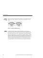
The programming language for functions is Tcl. The Tcl commands permit a
programmer to build conditional tests and create their own functions. The Tcl
interpreter in the AM700 allows imbedding SCPI commands in a function program
using the “scpi” Tcl command. The parser directs the SCPI commands appropriately. The Tcl command language is documented in Part I: The Tcl Language of the
book Tcl and the Tk Toolkit, by John K. Ousterhout: Addison-Wesley Publishing
Company, 1994.
Control Ports
The instrument may be controlled from the following sources:
The user operating the front panel keys, touch panel, and, for certain
operations, an external keyboard.
The GPIB port; a standard IEEE-488.2 interface.
Though it is not advised, whenever it is not explicitly disabled as part of the
protocol it is possible to control the instrument through both the front panel and the
GPIB interface port at the same time.
GPIB
Interface
Information
In normal GPIB remote operation the AM700 is controlled with an external
instrument controller. The only time the AM700 will attempt to take control of the
GPIB is when a hardcopy is requested from the front panel with the print port
configured to ‘GPIB’.
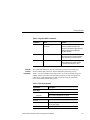
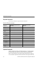
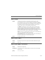
IEEE 488.1 Interface Functions. The GPIB interface function set implemented in
the AM700 GPIB interface and the capability level is given in Table 1–1.
1–2
AM700 Audio Measurement Set Programmer Manual
Getting Started
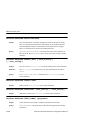
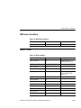
Table 1–1: IEEE 488.1 interface functions implemented in the AM700
IEEE 488.2
Commands
Function
Implemented
Notes
Source Handshake
SH1
Complete capability
Acceptor Handshake
AH1
Complete capability
Talker
T6
Basic Talker, Serial Poll, Unaddr if
MLA
Talker (extended)
TE0
No capability
Listener
L4
Basic Listener, Unaddr if MTA
Listener (extended)
LE0
No capability
Service Request
SR1
Complete capability
Remote Local
RL0
No local lock out
Parallel Poll
PP0
No capability
Device Clear
DC1
Complete capability
Device Trigger
DT0
No capability
Controller
C0
No capability
Electrical Interface
E2
Three-state bus drivers
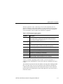
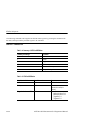
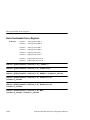
Complete details of IEEE 488.2 commands and operation are found in IEEE STD
488.2-1992, IEEE Standard Codes, Formats, Protocols, and Common Commands. A
brief summary of those implemented in the AM700 is given in the following tables.
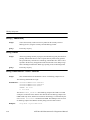
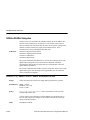
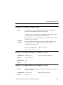
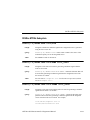
Table 1–2: IEEE 488.2 status reporting commands
Command
Name
Function
*CLS
Clear Status Command
Clears status data structures and forces
the device to the Operation Completed
Command Idle State and the Operation
Complete Query Idle State.
*ESE NRf
Standard Event Status Enable
Command
Sets the Standard Event Status Enable
Register bits.
AM700 Audio Measurement Set Programmer Manual
1–3
Getting Started
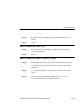
Table 1–2: IEEE 488.2 status reporting commands (cont.)
Command
Name
Function
*ESE?
Standard Event Status Enable
Query
Queries the contents of the Standard
Event Status Enable Register.
*ESR?
Standard Event Status Register Query
Queries the contents of the Standard
Event Status Register. Reading the
register clears it.
*SRE NRf
Service Request Enable
Command
Sets the Service Request Enable Register
bits.
*SRE?
Service Request Enable Query
Queries the Service Request Enable
Register. Returns an NR1 that is the value
of the service request enable register.
*STB?
Read Status Byte Query
Queries the status byte. Returns an NR1
that is the value of the status byte and the
master summary message.
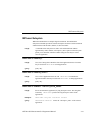
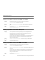
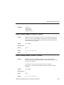
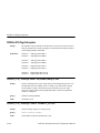
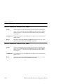
Table 1–3: Internal operation commands
1–4
Command
Name
Function
*IDN?
Identification Query
Queries the id of the AM700.
*RST
Reset Command
Does a AM700 reset.
*TST?
Self-Test Query
This is currently a “NO-OP” It is effect
just tests the remote connectivity and
does not change the operating state of
the AM700.
AM700 Audio Measurement Set Programmer Manual
Getting Started
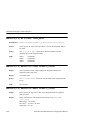
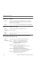
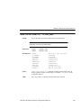
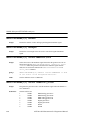
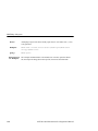
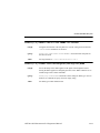
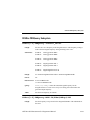
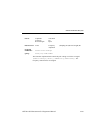
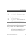
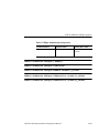
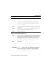
Table 1–4: Synchronization commands
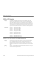
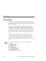
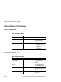
RS-232C
Interface
Information
Command
Name
Function
*OPC
Operation Complete
Command
Causes the AM700 to Generate the
operation complete message in the
Standard Event Status Register when all
pending selected device operations
have been finished.
*OPC?
Operation Complete Query
Places an ASCII “1” in the AM700’s
output queue when all pending selected
device operations have been finished.
*WAI
Wait-to-Continue Command
Prevents the AM700 from executing
further commands or queries until the
no-operation-pending flag is TRUE.
The COM1 and COM2 ports may be configured as serial RS-232C DTE ports.
These are DB-9 male connectors. The Serial Interface parameters given in
Table 1–5 are user selectable using menu control. If you are connecting the port to
another terminal, you will need a null modem connector to make the appropriate
connections. A user-supplied printer cable is needed to make the connection
between the AM700 and the user’s printer.
Table 1–5: Serial port protocol
Capabilities
Description
Serial ports
COM1 and COM2
Connector
RS-232C
DB-9, male. Configured as DTE ports.
Serial interface parameters
RS-232C
Baud Rate
User selectable: 300, 600, 1200, 2400, and 9600,
19,200, and 38,400.
Flow Control
XON/XOFF, CTS/RTS, and None.
AM700 Audio Measurement Set Programmer Manual
1–5
Getting Started
Table 1–5: Serial port protocol (cont.)
Serial interface parameters
1–6
Signal Bits
7 or 8
Stop Bits
1 or 2
Parity
Odd, Even, and None
AM700 Audio Measurement Set Programmer Manual
Getting Started
Rear Panel I/O Connectors
Figure 1–1: AM700 Rear Panel
GPIB
Connector
The GPIB connector (shown in Figure 1–2) provides a remote control interface to
the AM700. It is a standard IEEE 488 parallel GPIB connector. One- and two-meter,
double-shielded GPIB cables are available as optional accessories (refer to the
AM700 Audio Measurement Set User Manual).
GPIB
Figure 1–2: GPIB Connector
AM700 Audio Measurement Set Programmer Manual
1–7
Getting Started
COM1 and
COM2 Serial
Ports
These two male DB-9 connectors (shown in Figure 1–3) provide the interface for
RS-232C serial output as DTE ports. These connectors support RS-232C printer
output.
COM 1
COM 2
Figure 1–3: COM1 and COM2 serial ports
REMOTE
Connector
1–8
The Remote connector (shown in Figure 1–4) provides a user interface for
contact-closure remote control. The AM700 may use this port to control external
devices that are actuated via a contact-closure. The TTL-Level input may be used
with external contact-closure relay or switch to initiate an action for the AM700. A
possible use of this feature is to use a foot switch to signal the AM700 in a running
function for production line testing. This type of operation leaves the operator’s
hands free to make connections to the equipment under test and operate the AM700
making the measurements without having to have immediate access to the front
panel of the AM700. A function program has to be written with the appropriate
commands to make use of the remote connector for the operation just described.
AM700 Audio Measurement Set Programmer Manual
Getting Started
REMOTE
1
2
6
3
4
7
8
5
9
DB-9 FEMALE REMOTE CONNECTOR
Pin 1
Pins 2, 4, 6, 8
Pin 3 to Pin 9
Pin 5 to Pin 9
Pin 7
TTL-Level Input
Ground
Normally Open
Normally Closed
+5 V Output @ 5 mA
Figure 1–4: Remote contact-closure connector
Table 1–6: Remote connector pins
Remote connector
Control Type
Contact Closure
Connector
DB-9, female
Pin 1, TTL
Level Input
0 to +5V, 100 mA. Input is protected. Use the +5 V
output of pin 7 to drive this input via an external
contact-closure relay. The state of the TTL input
(HIGH or LOW) can be read and used as an external
trigger input.
Pins 2, 4, 6, and 8
Ground
AM700 Audio Measurement Set Programmer Manual
1–9
Getting Started
Table 1–6: Remote connector pins (cont.)
Remote connector
Pin 3 to Pin 9,
Contact Closure
Normally open. Maximum voltage: 220 VDC;
Maximum current: 2 A; Maximum power: 60 W.
The state of the contact-closure relay (open or closed)
is settable from a function key and using SCPI
remote control.
Pin 5 to Pin 9
Reserved, normally-closed contact
Pin 7, +5 V Output
+5 V @ 5 mA. This output is provided to drive the
TTL-Level input through an external contactclosure relay.
System Communication
The Communication selections shown in Figure 1–5 provide the choices needed to
define the serial communications parameters for serial ports COM1 and COM2, and
setting the GPIB communications mode and the GPIB address. The conventional
choices in serial communications of Baud rate, stop bits, parity, hardware handshaking, and software handshaking for RS-232 are provided. With the first release,
the serial ports are unidirectional, output only, for support of serial printers.
GPIB choices permit you to select the mode of operation and the GPIB address of
the AM700. GPIB modes of operation are Talk/Listen, Hardcopy, and Off Bus.
Talk/Listen mode is used for remote control of the AM700 via the GPIB port.
Hardcopy is the talk only mode and is used to output screens and data to a GPIB
printer. Off Bus turns of the GPIB interface, and the AM700 will not communicate
with any other device on the bus.
1–10
AM700 Audio Measurement Set Programmer Manual
Getting Started
Figure 1–5: Configure system setup communicate menu
Connecting Printers
This topic discusses connecting an EPSON LQ, Apple LaserWriter, HP LaserJet,
DeskJet, or ThinkJet, or generic ASCII printer to the AM700.
Connecting
an EPSON LQ
Printer
The default configuration is set for use with the EPSON LQ letter quality printer
with serial interface C 823051. The default configuration of the EPSON LQ printer
is adequate for use with the AM700. Refer to the user’s manual for your printer for
information on any changes you might wish to made to the printer setup.
With the AM700 and printer power off, connect the serial printer cable from the
25-pin DB-25 female connector on the printer’s rear panel to COM2 on the back of
the AM700 (a 9-pin DB-9 male connector). If you have not changed the factory
AM700 Audio Measurement Set Programmer Manual
1–11
Getting Started
default values, all you need to do now is turn on the AM700 and the printer. If you
have changed some factory default values, be sure the values shown in the following
example are set.
Making Your Own LQ Cable. If the correct printer cable is not readily available,
one can be easily constructed. A male 25-pin DB-25 connector, a female DB-9
connector, and an appropriate length of four-conductor cable are the materials
needed for the cable. Table 1–7 lists the wiring connections for making a cable to
use with an Epson LQ printer.
Table 1–7: Epson LQ cable connections
ÁÁÁÁÁÁÁÁÁÁÁÁ
ÁÁÁÁÁÁÁÁÁÁÁÁÁ
ÁÁÁÁÁÁÁÁÁÁÁÁ
ÁÁÁÁÁÁÁÁÁÁÁÁÁ
ÁÁÁÁÁÁÁÁÁÁÁÁ
ÁÁÁÁÁÁÁÁÁÁÁÁÁ
ÁÁÁÁÁÁÁÁÁÁÁÁ
ÁÁÁÁÁÁÁÁÁÁÁÁÁ
ÁÁÁÁÁÁÁÁÁÁÁÁ
ÁÁÁÁÁÁÁÁÁÁÁÁÁ
ÁÁÁÁÁÁÁÁÁÁÁÁ
ÁÁÁÁÁÁÁÁÁÁÁÁÁ
Connecting
an Apple
LaserWriter
Male DB-25 connector pin number (Epson
LQ end)
Female DB-9 connector pin number
(AM700 end)
1 (shield ground)
shield ground
3 (RXD)
3 (TXD)
20 (DTR)
8 (CTS)
7 (signal ground)
5 (signal ground)
Note the following when connecting an Apple LaserWriter to a AM700 serial port:
Setting Up The AM700. Set the selected port’s Baud Rate to 9600, Flow Control to
XON/XOFF, Character Size to 8, Reset Character to Ctrl-D, and Carrier Detect
to Disabled.
Setting Up The LaserWriter. Set the rear panel switch to the 9600 position.
The cable connecting the AM700 and the LaserWriter should be wired as described
in Table 1–8. The cable must have a female DB-9 connector on the AM700 end and
a male DB-25 connector on the LaserWriter end.
1–12
AM700 Audio Measurement Set Programmer Manual
Getting Started
Table 1–8: Apple LaserWriter connections
ÁÁÁÁÁÁÁÁÁÁÁÁ
ÁÁÁÁÁÁÁÁÁÁÁÁÁ
ÁÁÁÁÁÁÁÁÁÁÁÁ
ÁÁÁÁÁÁÁÁÁÁÁÁÁ
ÁÁÁÁÁÁÁÁÁÁÁÁ
ÁÁÁÁÁÁÁÁÁÁÁÁÁ
ÁÁÁÁÁÁÁÁÁÁÁÁ
ÁÁÁÁÁÁÁÁÁÁÁÁÁ
ÁÁÁÁÁÁÁÁÁÁÁÁ
ÁÁÁÁÁÁÁÁÁÁÁÁÁ
ÁÁÁÁÁÁÁÁÁÁÁÁ
ÁÁÁÁÁÁÁÁÁÁÁÁÁ
ÁÁÁÁÁÁÁÁÁÁÁÁ
ÁÁÁÁÁÁÁÁÁÁÁÁÁ
ÁÁÁÁÁÁÁÁÁÁÁÁ
ÁÁÁÁÁÁÁÁÁÁÁÁÁ
Connecting
an HP
LaserJet,
DeskJet, or
ThinkJet
Male DB-25 connector pin number (Apple
LaserWriter end)
Female DB-9 connector pin number
(AM700 end)
1 (shield GND)
shield GND
3 (RXD)
3 (TXD)
2 (TXD)
2 (RXD)
5 (CTS)
7 (RTS)
4 (RTS)
8 (CTS)
7 (signal GND)
5 (signal GND)
You will have to configure both the AM700 and the printer to respond correctly.
Setting up the AM700. In Configure menus under System Setup Copy set the Copy
Format to HP printer type. Select the output port from the Copy Destination
choices.
Setting up the port for communications is done in the Configure menus under the
System Setup Communicate choices, shown in Figure 1–5. For the selected port, set
the Baud Rate to any value from 300 to 19200, set Protocol to None, Flow Control
to XON/XOFF, Reset Character to None, Parity to None, Character Size to 8, and
Carrier Detect to Disabled.
Setting up the HP LaserJet, DeskJet, or ThinkJet. Set the baud rate to the same as
the AM700.
Making Your
Own LaserJet
Cable
Table 1–9 lists the wiring connections for making a cable to use with an HP LaserJet
printer.
AM700 Audio Measurement Set Programmer Manual
1–13
Getting Started
ÁÁÁÁÁÁÁÁÁÁÁÁ
ÁÁÁÁÁÁÁÁÁÁÁÁÁ
ÁÁÁÁÁÁÁÁÁÁÁÁ
ÁÁÁÁÁÁÁÁÁÁÁÁÁ
ÁÁÁÁÁÁÁÁÁÁÁÁ
ÁÁÁÁÁÁÁÁÁÁÁÁÁ
ÁÁÁÁÁÁÁÁÁÁÁÁ
ÁÁÁÁÁÁÁÁÁÁÁÁÁ
ÁÁÁÁÁÁÁÁÁÁÁÁ
ÁÁÁÁÁÁÁÁÁÁÁÁÁ
ÁÁÁÁÁÁÁÁÁÁÁÁ
ÁÁÁÁÁÁÁÁÁÁÁÁÁ
ÁÁÁÁÁÁÁÁÁÁÁÁ
ÁÁÁÁÁÁÁÁÁÁÁÁÁ
ÁÁÁÁÁÁÁÁÁÁÁÁ
ÁÁÁÁÁÁÁÁÁÁÁÁÁ
ÁÁÁÁÁÁÁÁÁÁÁÁ
ÁÁÁÁÁÁÁÁÁÁÁÁÁ
ÁÁÁÁÁÁÁÁÁÁÁÁ
ÁÁÁÁÁÁÁÁÁÁÁÁÁ
Table 1–9: HP LaserJet cable connections
Connecting
an ASCII
Printer
Male DB-25 connector pin number (HP
LaserJet end)
Female DB-9 connector pin number
(AM700 end)
1 (shield ground)
shield ground
3 (RxD)
3 (TXD)
2 (TxD)
2 (RXD)
7 (signal ground)
5 (signal ground)
5 (CTS), 6 (DSR), and 8 (DCD)
4 (DTR)
20 (DTR)
8 (CTS), 6 (DSR), and 1 (DCD)
The AM700 can also be configured to operate with a generic ASCII printer. A
generic ASCII printer is assumed to only print text; graphic functions are not
supported.
Hardcopy Output
Hard copies of data, screens, files, limits, and other data outputs of the AM700 will
be available on printers or plotters connected to RS-232C or GPIB ports.
Pressing the Copy button sends a copy of the display in the selected format to the
print spooler (temporary memory space) where it is queued for printing. The LED in
the Copy button flashes as long as the copy remains in the spooler.
To select the output format for a copy, you must use the menu selections for Copy
found in the Configure menu under System Setup. Press and hold the Copy button to
display the Copy Configuration screen (see Figure 1–6).
NOTE. Pressing and holding the Copy button immediately brings up the
Configure menu, with the System Setup choices for Copy displayed. This
is the same screen that is displayed by pressing the Configure button,
then System Setup, and then Copy.
1–14
AM700 Audio Measurement Set Programmer Manual
Getting Started
In this screen you may set the following copy functions:
Copy output format
Copy destination
File name when File is the selected copy destination
After setting copy options, touch the Accept Changes soft key to save your
selections, exit the Copy Configuration screen, and return to the measurement
display.
Figure 1–6: The copy configuration menu
Delete all copies from the spooler by pressing and holding the copy button to
display the Copy Configuration menu. Then touch the Cancel Pending Hardcopy
soft key.
AM700 Audio Measurement Set Programmer Manual
1–15
Getting Started
Screen dumps print when you press the Copy button. The image currently on the
screen is printed. Graphic displays are printed only when the printer port is
formatted for a graphics printer.
Copy Formats
The AM700 supports the following printer and hard-copy types:
PostScript Image
HP DeskJet
Epson (24 pin)
Tag Image File Format (TIFF)
Interleaf Image
When the Copy Format is either PostScript or TIFF the Copy Style may be set to
Color.
Copy
Destination
Printouts are spooled to the currently selected printer port, which may be one of the
following:
GPIB
COM 0 or COM 1 (RS-232)
File on floppy disk
File in internal nonvolatile file system
None (This choice disables hard copy output.)
When the Copy Destination is set to File, the Output File selection is active. This
choice brings up a file browser, shown in Figure 1–7, to let you select or name the
output file name for the hard copy. You may name a file by touching the Filename
soft key. This displays a keyboard to type in the new file name. Hard copy files may
be sent directly to the floppy disk for later printing. A limited number of screen
dumps may be stored in NVRAM for later transfer to a floppy disk. The available
memory in the internal NVRAM of the AM700 depends on how much of the
memory is used for other user files.
1–16
AM700 Audio Measurement Set Programmer Manual
Getting Started
Figure 1–7: Hard Copy output file selector
Copy Styles
This controls the choice of the color output for PostScript and TIFF formatted files.
When set to Color, printer output will be color formatted. If a copy format other
than PostScript or TIFF is used, the Color state is ignored, and the file is output as
monochrome (gray scale) only.
AM700 SCPI Control Model
The AM700 functional areas are divided as to task to perform. In a like manner
SCPI commands are organized to command the task required in each functional
area. The AM700 is logically divided between its hardware functions needed to
acquire signals for processing and the display of the results and its software
functions that do the signal processing needed to produce the measurement results.
The measurement results in most cases, consist of a display trace of the acquired
AM700 Audio Measurement Set Programmer Manual
1–17
Getting Started
data after processing and numerical values of key features of a measurement.
Examples of display numerical value are the amplitude at a frequency, the frequency
at a cursor location, the THD + N, etc.
An illustration (see Figure 1–8) of how the AM700 is modeled for SCPI control is a
useful start in determining which SCPI system and subsystem commands are used to
control the AM700 functions. After that connection is made, the actual SCPI
commands required to perform a measurement task may be developed.
Input signals
ROUTe
Signal routing only;
no processing
INPut
Analog processing
SENse
Conversion to digital
CALCulate
TRACe
Measurements
To display
Figure 1–8: AM700 SCPI systems for measurements
AM700 Analog Signal Path
In the AM700, the hardware of the analog signal path is organized in functional
blocks. These blocks are assigned SCPI System commands related to the functions
to be done as shown in Figure 1–9. Signal Routing is shown in Figure 1–10.
1–18
AM700 Audio Measurement Set Programmer Manual
Getting Started
Acquisition Ch A
ROUTe
Select
Impedance
Gain/Attnuation
INPut
THD Notch
Select
Select
High res ADC
High BW ADC
SENse
Decimation
Select
Figure 1–9: Analog hardware SCPI system subsystems
Some of the hardware choices are user selectable depending on the measurement
application in use. Examples of these choices are the channel to be acquired and
whether the measurement will be in High Resolution Mode or in High Bandwidth
Mode. Other hardware choices are made as required by the measurement application
selected by the user.
AM700 Audio Measurement Set Programmer Manual
1–19
Getting Started
Signal
Routing
Input
Sense
Acquisition channel A
Analog A input
generator A
ROUTe1
INPut1
SENSe1
INPut2
SENSe2
High RES
High BW
CSTR1:FEED ’SENS1’
CSTR2:FEED ’SENS3’
CSTReam1
CSTReam2
Acquisition channel B
Analog B input
generator B
ROUTe2
INPut3
SENSe3
INPut4
Front panel XLR
Rear panel BNC
Rear panel optical
Digital main
ROUTe3
SENSe4
SENSe5
SENSe7
DSP Port
Digital main
A
B
A
To CALCulate
INPut6
SENSe8
Rear panel
reference
High BW
INPut5
SENSe6
Rear panel DSP
High RES
Digital
reference
SENSe9
B
A
INPut7
SENSe10
B
SENSe11
Eye pattern
Figure 1–10: AM700 signal routing to CSTReam
AM700 Signal Selection and Routing
Signals to acquire must be selected and routed to the CALCulate blocks for
measurement. Since the AM700 has multiple input choice for analog and digital
1–20
AM700 Audio Measurement Set Programmer Manual
Getting Started
signals, the routing commands take on suffixes and channel_list numbers to provide
the control needed. Figure 1–10 illustrates the selection paths available in the
AM700.
ROUTe
Subsystem
The ROUTe Subsystem commands are used for switching signals in the input. No
processing is done. To use the ROUTe commands, selectable routes must have a
numerical assignments.
In the AM700 the route and close suffix numbers are as follows:
ROUTe suffixes:
1
2
3
Analog acquisition channel A
Analog acquisition channel B
AES/EBU digital audio
CLOSe <channel_list> indices:
1
2
Analog input channel A
Analog input channel B
3
4
Analog generator channel A
Analog generator channel B
6
7
8
9
Balanced (FP) digital audio
Unbalanced (RP) digital audio
Optical (RP) digital audio
AES Generator
AM700 Audio Measurement Set Programmer Manual
1–21
Getting Started
Syntax:
ROUTe[1|2|3]:CLOSE <channel_list>
or
ROUTe[1|2|3]:CLOSE:STATE?
Only certain closures go with a given route: The acceptable routes and closures are:
rout1:clos 1|3
rout2:clos 2|4
rout3:clos 6|7|8|9
Example:
The Close command allows specific individual channels to be closed or
queried. To select the generator as the signal source for the Analog A input, the
command is:
ROUT1:CLOS 3
The rout2[1|2|3]:close:state? query returns the <channel_list> number
for the designated route. If all the specified channels cannot be closed (trying to
close two channels at the same time if that is not allowed) an execution error is
reported. See the ROUTe Subsystem Command description in Section 3 for
complete information on the route command as used in the AM700.
INPut
Subsystem
Suffixes:
The Input subsystem commands set the conditions prior to sampling. Here the
choices of input impedance and input range are made. The input choices are also
user selectable from within some measurement applications. The choices of
selecting the filtered output are not is a measurement choice that will be made as
needed by the application. Selections for the notch filter range and use are not
selectable via remote control.
Suffixes are: INP1
INP3
Analog acquisition channel ‘A’
Analog acquisition channel ‘B’
The syntax for the Input commands is as follows:
Syntax:
1–22
INPut:RANGe 0.0870 to 173.616
INPUT:IMPedance 150|600|200000
AM700 Audio Measurement Set Programmer Manual
Getting Started
Range. The AM700 treats attenuation and gain as joined parameters that define the
input range setting. A range window has a dynamic range of approximately 100 dB,
but the location of the range window may be positioned within overall dynamic
range of approximately +44 to –122 dBu. The numeric value in the Range command
is the level at which the input signal will clip (the maximum signal level for the
range window). The default range setting is AUTO. In AUTO, the input signal is
examined and the range window is positioned to produce a useful measurement on
the applied signal. Setting the range to a specified value turns off AUTO.
Syntax:
Example:
INPUt:RANGe:AUTO <Boolean>|ONCE
INPut:RANGe <numeric_value>
The first of the two following examples turns autoranging on; the second sets
the signal clipping level at +35 dBu.
INPut:RANGe:AUTO ON
INPut:RANge 43
Range:
The numerical_value for range is 0.0870 to 173.616 volts in 12, 6 dB steps:
dBu
Volts
–18.9911 0.0870
–12.9911 0.1736
–6.9911 0.3464
–0.9911 0.6911
5.0089 1.3789
11.0089 2.7512
17.0089 5.4893
23.0089 10.9527
29.0089 21.8535
35.0089 43.6034
41.0089 87.0003
47.0103 173.6160
Setting the value for a number that is in between the step settings defaults the range
to the next highest valid range step. For example, if you set it for 2 volts, the actual
setting will be 2.7512 for clipping at approximately 11 dBu.
AM700 Audio Measurement Set Programmer Manual
1–23
Getting Started
IMPedance. Another choice in the Input subsystem is the input impedance setting.
The Input command in the AM700 uses suffixes to designate the input that has the
impedance setting applied. Syntax for the Impedance command is as follows:
Syntax:
Example:
INPut:IMPedance <numeric_value>
This command sets the input impedance for Analog A to 600 ohms.
INPut1:IMPedance 600
or
inp:imp 600
Range:
The input impedance choices are: 150, 600, and 200000 ohms with 200000
being the power on default.
SENSe
Subsystem
The SENSe setup commands are used to control some parameters of the digital
audio measurement function, and to query measurements made on the digital
interface. Commands in this subsystem are used to control the acquisition methods
of the AM700. Commands under the :DATA:DAUDio subnode control how digital
audio signals are acquired and queries to determine measurements. The Sense
commands uses the following suffixes to direct the action of the Sense command.
Analog Sense is controlled by the applications as needed to perform the selected
measurements.
Suffixes:
SENSe suffixes:
5
6
7
8
9
10
11
Subframe ‘A’ digital audio
Subframe ‘B’ digital audio
DSP port ‘A’
DSP port ‘B’
Digital reference ‘A’
Digital reference ‘B’
Eye Pattern
A few SENSe commands related to the digital audio signal are the following:
Syntax:
SENSe[5–8]:DAUDio:AUDio:SRATe?
Returns the sample rate of the incoming signal.
LOW is 32 kHz
MEDium is 44.1 kHz
HIGH is 48 kHz
1–24
AM700 Audio Measurement Set Programmer Manual
Getting Started
SENSe[5–8]:DAUDio:INTerface:BWIDth LOW|MEDium|HIGH
SENSe[5–8]:DAUDio:INTerface:JGAin NORMal|HIGH
CSTReam
Subsystem
Example:
CSTReam commands direct the appropriate Sense output to the measurement
channels. The choices are constrained to appropriate selections by the applications.
The sense choices are fed to the FFT Analyzer calculate blocks by a
CSTReam:FEED command using the following syntax.
CSTReam1:FEED SENSe1
CSTReam2:FEED SENSe3
CSTReam1:FEED SENSe5
CSTReam2:FEED SENSe6
or cstr1:feed sens1
etc.
Coupled
Commands:
CALCulate
Subsystem
Suffixes:
In the first example, cstream1 is fed by the output of sense1, the Analog A
high resolution A/D converter, and cstream2 is fed by sense3, also the high
resolution A/D converter. In example two, the cstreams are fed by the digital
audio channel A and channel B signals.
A number of independent subsystems comprise the CALCulate subsystem. Each of
the subsystems is a sub-block of the CALCulate block. Data flows through the
sub-blocks in serial fashion. The CALCulate block has more than one instance of
some of the sub-blocks. The same named sub-blocks are differentiated by a numeric
suffix. The syntax of the CALCulate subsystem commands are application
dependent. One example of the signal flow in show in Figure 1–11. It illustrates the
FFT CALCulate subsystem.
CALCulate1
CALCulate2
CALCulate3
CALCulate4
Trace1 Zoom
Trace2 Zoom
Trace1 Average
Trace2 Average
AM700 Audio Measurement Set Programmer Manual
1–25
Getting Started
FFT Analyzer SCPI Commands. In the FFT Analyzer, the calculate blocks are
separated by channels and function. Calculate1 is used for the fft zoom functions of
channel 1 and is fed by the CSTReam1 feed. Calculate2 is also used for the fft zoom
functions, but for channel 2. It is fed by the CSTReam2 feed where the feeds are one
of the SENSe signals. Calculate3 and Calculate4 control the averaging commands of
the FFT Analyzer. As with calc1 and calc2 there are two channels, and calc3
controls the averaging on channel 1 while calc4 controls the averaging on channel 2.
HARD WIRE
CSTReam1
CALCulate1
:FEED CSTReam1
HARD WIRE
CSTReam2
CALCulate2
:FEED CSTReam2
CALCulate1:
CALCulate3:
CALCulate5:
Zoom FFT
Averaging
Log
TRACe1:DATA?
CALCulate1
:TRANsform
:FREQuency
:STARt <numeric_value>
:CENTer
CALCulate2:
CALCulate4:
CALCulate6:
Zoom FFT
Averaging
Log
TRACe2:DATA?
CALCulate4
:AVERage
:COUNt <numeric_value>
:AVERage
STATe ON|OFF
AVERage?
Figure 1–11: FFT CALCulate subsystem block
1–26
AM700 Audio Measurement Set Programmer Manual
Getting Started
The FFT Analyzer application also contains the Multitone measurement calculate
blocks. A special SCPI command switches the FFT Analyzer between the two
functions as shown in Figure 1–12. The calculate block results are given different
trace names. The trace names for the FFT calculate block results are found using the
TRACe:CAT? command. The reply to the query is application specific and returns
the names for the Audio Analyzer traces when that application is running.
Measurement
Input 1
CMODe:FFT FFT|MTONe
CALCulate FFT
Result1
Result2
Result3
Result4
TRACe:CAT?
TRACe:DATA? FFTMAG_1
DISPlay
CSTReam1
CALCulate
MULTITONE
Result9
Result10
Result11
Result12
Measurement
Input 2
Result5
CALCulate FFT
Result6
Result7
Result8
CALCulate
MULTITONE
Result13
Result14
Result15
Result16
CSTReam2
Figure 1–12: Switching Between FFT and Multitone
AM700 Audio Measurement Set Programmer Manual
1–27
Getting Started
AMEasure
Subsystem
Suffixes:
The AMEasure subsystem provide commands that set up the AM700 to perform
selected measurements and to control some parameter settings of applications. The
commands are application specific. The majority of the AMEasure commands are
used for the Audio Analyzer application. These commands include those used to
control settling time, command regulation mode, and select the measurements to be
done by the Audio Analyzer.
AME1
AME2
AME3
AME4
MEAS 1
MEAS 2
MEAS 3
MEAS 4
FFT and the AMEasure Subsystem. FFT supports 5 separate measurements. They
are as follows:
AMEasure1: FFT on channel 1
AMEasure2: FFT on channel 2
AMEasure3: Configurable Multitone
AMEasure4: Configurable Multitone
AMEasure5: Configurable Multitone
These measurements ‘assignments are described by the the AME:MODE command.
FFT implements AME:MODE, with the following initial values for each suffix
combination:
AME1:MODE FFT
AME2:MODE FFT
AME3:MODE MTONe
AME4:MODE MTONe
AME5:MODE MTONe
TRACe
Subsystem
1–28
The trace subsystem contains measurement results for display and remote query.
Trace queries are used to return the measurement data held in a trace. Different
AM700 Audio Measurement Set Programmer Manual
Getting Started
traces are selected by trace name; not suffixes. Trace commands are also application
specific and will change with the Instrument selection.
A useful query in the Trace subsystem is one that returns the names of the defined
traces.
Query:
TRACe:CATalog?
or
trac:cat?
If there are no named traces, a single empty string is returned. When multiple traces
are defined, the names are returned in a comma separated list of trace_name strings.
A listing of the possible trace names by application is provided in the TRACe
subsystem commands in AM700 SCPI Commands, Section 3.
DISPlay
Subsystem
The display commands control the number and type of displays that are available
for a running application. The adjustments available in the DISPlay subsystem
include controlling display brightness, turning on and off view windows (graphs,
text, and generator control panel), enabling and positioning cursors, entering text in
a text view window (dialog box), assigning X- and Y-axis scales, and switching the
graphical plotting methods (point-to-point, linear or logarithmic). The complete set
of commands for the DISPlay subsystem are given in AM700 SCPI Commands,
Section 3.
Windows 1 through n specify the view windows in the application. Presently, there
are four graphical displays, WIN1 through WIN4, the Real Time measurement
readouts, WIN5, the Generator Status display, WIN60, the notifier displays,
WIN98, and a text dialog box, WIN99.
SYSTem
Subsystem
Status, ID, errors, and other required interface type operations related to running the
AM700 remotely are included in the SYSTem commands. A following query of the
system commands is very useful:
SYSTem:ERRor?
This query returns error messages from the error message stack until all messages
have been read. If no error exists, it returns “0, NO ERROR.”
AM700 Audio Measurement Set Programmer Manual
1–29
Getting Started
Also found in the system commands are the ones used for setting the communications parameters for RS-232 communications (baud rate, data bits, and parity) and
the GPIB address and the following commands for setting and querying the internal
clock of the AM700:
SYST:TIME?
SYST:DATE?
STATus
Subsystem
The STATus subsystem controls the status-reporting structures of the AM700. These
structures conform to the IEEE 488.2 specification. The different structures may be
looked at a set of registers: these are a condition register, an event register, an enable
register, and negative and positive transition filters. The AM700 is multiple logical
instruments and provides for the QUEStionable and OPERation registers. These
registers are further subdivided into other groupings as follows:
QUEStionable:INPut:SUMMary
QUEStionable:SOURce:SUMMary
QUEStionable:INSTrument
QUEStionable:SOURce
QUEStionable:INPut
OPERation:TRIGger
OPERation:SYSTem
OPERation:INSTrument
There is a queue for status. The queue provides a human readable record of
instrument events. A programmer may individually enable events into the queue.
INSTrument
Subsystem
Usage:
1–30
Within the AM700 there are multiple logical instruments. The INSTrument
subsystem commands provide the controls and queries needed to switch instruments
and the find out what the name, number, or short form name.
Commands in this subsystem are used to switch between AM700 applications
either by name or number. Several query commands are used to return the
names and application numbers. These are the several versions of catalog
queries. The catalog queries, INST:CAT, INST:CAT:FULL, INST:LCAT, and
INST:LCAT:FULL all return comma separated list of the application name
strings. Instruments are selectable by number, short name, and long name.
AM700 Audio Measurement Set Programmer Manual
Getting Started
Syntax:
Query:
INST:NSEL <app_number>
INST:NSEL? returns the number of the selected application.
Syntax:
Query:
INST:SEL <app_name>
INST:SEL? returns a short form name for the selected application.
Syntax:
Query:
INST:LSEL app_descriptive_name
INST:LSEL? returns a long descriptive name of the selected application.
Range:
NSEL
1
2
3
4
5
6
MMEMory
Subsystem
SEL
FFT
Analyzer
Monitor
Digital
Diagnostics
PanelCal
LSEL
‘FFT analyzer’
‘Audio analyzer’
‘Monitor’
‘Digital Interface Tester’
‘Diagnostics’
‘Touch Panel Calibration’
The Mass Memory subsystem behavior in the AM700 is very similar to to the
documented SCPI behavior. One major divergence form standard SCPI is the
absence of msus (mass storage unit specifier) support in the AM700. The
AM700 allows an optional mass storage unit specifier with any filename given to
the MMEMory commands. The syntax of the file name is:
<[device:]{/path_name/path_name/}<file_name>
The device portion is optional.“device” can be one of “rom”, “nvram”, or “dos”.
Once past the device specification, the name looks pretty much like a UNIX file
name. Slashes separate the path-name components.
Mass MEMory provides mass storage capabilities for the AM700. Mass storage is
either internal or external and the AM700 supports both.
The CLOSe, FEED, NAME, and OPEN commands are used to stream data from
anywhere in the data flow into a file for saving HCOPy output.
Mass storage media may be formatted in one of a number of standard formats. The
AM700 does not support the SCPI mass storage unit specifier <msus>.
AM700 Audio Measurement Set Programmer Manual
1–31
Getting Started
AM700 File Structure. The upper level of the AM700 files comprise ROM, NVRAM,
and DOS logical directories. Under those, other directories or files may exist.
Certain directories are accessible by the user for storage use or information.
File Names. The <file_name> parameter in the MMEMory subsystem is a string.
The contents of the string are dependent on the needs of the format of the mass
storage media. In particular, the file name may contain / for specifying sub-directories.. File names may be absolute, rooted, or relative. Absolute file names use the
complete name with device and total path to the file. Rooted file names use the path
within a designated device and may be used after changing directory to that device.
Relative file names are assumed to be in the current working directory.
Note that this syntax places some restrictions on the <file_name> (for example,
commas are not allowed).
The AM700 allows an optional mass storage unit specifier (a logical directory
name) with any file name given to the MMEMory commands. The syntax of the file
name is:
<[device:]{/dir_name/dir_name/}<file_name>
dos:/directory/filename
nvram:/directory/filename
rom:/directory/filename
The device and path portions are optional and not needed if the file name is in the
current working directory. “device” can be one of “rom”, “nvram”, or “dos”. Legal
dos file names are permitted. That is a file name of eight characters maximum
length followed by a file extension up to three characters in length. Filenames are
not case sensitive and must be single quoted in the SCPI commands. An example is:
MMEM:DEL nvram:/function/usrtone1.ton
Moving Between Directories. Changing directories is done using the MMEMemory:CDIRectory command as follows:
MMEM:CDIR dos:/
MMEM:CDIR nvram:/function
MMEM:CDIR rom:/function
1–32
AM700 Audio Measurement Set Programmer Manual
Getting Started
MMEM:CDIR ..
To list the files in a directory use the MMEMemory:CATalog? query. First change
directory to the one you are interested in, and then cat the directory.
MMEM:CDIR nvram:/function or
MMEM:CDIR dos:/
MMEM:CAT?
This returns a comma separated list of the directories and files in the directory and
the number of bytes they contain.
Copy a dos file from a floppy disk into the nvram function file using the MMEMemory:COPY command as follows:
MMEM:COPY dos:/filename,nvram:/function/filename
PROGram
Subsystem
The PROGram subsystem as implemented in the AM700 is for the selection and
running of functions. These commands provide features needed to generate and
control one or more user-programmed tasks in the AM700. Functions are files in
Tcl programming language permanently included in the “rom:/functions” directory
and any user generated files in the “nvram:/functions” directory. The function names
are the file names found in those two directories.
Function programs may be loaded either using the DOS file transfer capabilities of
the MMEMory subsystem or using the PROGram subsystem commands for
unloading via the GPIB interface. Function programs loaded using the GPIB
interface must be formatted as arbitrary block program data. Function programs may
be loaded from a floppy disk through the DOS interface using the file browser
screens called up when the front panel Storage button is pressed. Refer the Function
information in the Examples section for more information on writing and running
functions.
GCONtrol
Subsystem
Selection of the generator modes and controlling the output states is done using the
special commands of the GCONtrol subsystem. Signal selection is done using the
SOURce commands. See the block diagram in Figure 1–13.
AM700 Audio Measurement Set Programmer Manual
1–33
Getting Started
GCONtrol MODE Commands. The following commands control the generator
signal source. The first sets either the high resolution generator or the high
bandwidth generator for the analog signal. The second determines whether the
digital mode signal is output from the digital main generator (AES) or the digital
signal processor (DSP).
GCONtrol:ANALog:MODE HRes|HBW
GCONtrol:DIGital:MODE AES|DSP
1–34
AM700 Audio Measurement Set Programmer Manual
Getting Started
GCONtrol:ANALog:MODE HRes|HBW
GCONtrol:OUTPut:STATe ON|OFF
OUTPUT CONNECTORS
SOURce1
high
resolution
high
bandwidth
OUTPut1
Analog generator Channel A
SOURce2
OUTPut2
SOURce3
Analog generator Channel B
SOURce4
Analog Generator
GCONtrol:DIGItal:MODE AES|DSP
Digital Audio Generator
SOURce5
digital
main
digital
DSP
digital
reference
OUTPut3
SOURce6
Digital generator channels A and B
SOURce7
OUTPut4
DSP generator channels A and B
SOURce8
SOURce9
OUTPut5
Digital reference channels A and B
SOURce / OUTput Subsystem
Figure 1–13: GCONtrol subsystem for the AM700 generator
Generator Output Commands. The Output subsystem commands control
connecting the generator signals to the appropriate output connector or other
signal path.
GCONtrol:OUTPut:STATe ON|OFF
GCONtrol:OUTPut:STATe?
AM700 Audio Measurement Set Programmer Manual
1–35
Getting Started
SOURce Subsystem Commands. Commands in the source subsystem control the
signal selections from the AM700 generator. The commands are divided between
those used to control the digital generator and those used to control the analog
generator. SOURce suffixes are used to provide the necessary identification.
Suffixes:
SOURce1 is analog generator HR A
SOURce2 is analog generator HR B
SOURce3 is analog generator HB A
SOURce4 is analog generator HB B
SOURce5 is digital generator A
SOURce6 is digital generator B
SOURce7 is DSP A
SOURce8 is DSP B
The generator output for Analog high resolution may be different signals on each
channel. For high bandwidth, both channels output either the same signal or either
output may be set to send silence.
Setting the type of signal output wanted from the generator is done using commands
of the following syntax:
SOURce[1–8]:FUNCtion:SHAPe
[SINusoid|JSINe|TBURst|CIMD|SIMD|
PRNoise|PCHirp|POLarity|TPolarity|MTONe|USER]
where each of the shape parameters is a different signal type available from the
generator.
1–36
AM700 Audio Measurement Set Programmer Manual
SCPI Conformance Information
SCPI Conformance Information
The AM700 commands are based on SCPI VERSION 1994.0.
SCPI Command Subsystems Implemented in the AM700
Table 2–1: SCPI subsystems implemented in the AM700
Subsystem
Use in the AM700
CALCulate
Averaging and FFT parameters
CALIBration
Calibration start and Conversion Factors
DISPlay
Selection and presentation styles for data and
controlling the view windows and cursors
FORMat
Sets program names to either character or string
data types.
HCOPy
Formatting and output of screen dumps.
INPut
Selection of input parameters
INSTrument
Selection of Application
MMEMory
AM700 memory commands
OUTPut
Selection of output parameters
PROGram
Control of the function programs
ROUTe
Selection of input routing
SENSe
Selection of input processing
SOURce
Selection of generator
STATus
Setting and querying the AM700 status registers
SYSTem
Control of the communication parameters,
hardcopy operation, setting the clock
TRACe
Querying the displayed traces for name, number of
points, and trace data
AM700 Audio Measurement Set Programmer Manual
2–1
SCPI Conformance Information
Table 2–1: SCPI subsystems implemented in the AM700 (cont.)
Subsystem
Use in the AM700
TRIGger
Starting and stopping the sweep
UNIT
Selection of units for input or output of certain
parameters. Trace data does not follow units.
Table 2–2: New command subsystems implemented in the AM700
2–2
Subsystem
Use in the AM700
AMEasurement
Controls the measurement setups for Audio
Analyzer, FFT Analyzer, Digital Interface Tester,
and the Audio Monitor.
CMODe
Controls selection of modes within an application
CSTReam
Directs the two measurement channels into the
CALC blocks.
GCONtrol
Controls the Audio Generator
AM700 Audio Measurement Set Programmer Manual
SCPI Conformance Information
SCPI Background Information
Reference: Standard Command for Programmable Instruments, SCPI 1994.
Instruments that conform to the 1993 SCPI standard will be able to meet the
requirements of IEEE Std. 488.1-1987 Standard Digital Interface for Programmable
Instrumentation and IEEE Std. 488.2-1987 Codes, Formats and Common Commands
For Use With IEEE Std. 488.1-1987. Conformance to the standards just mentioned
is not required in recognition that some instruments use hardware interfaces other
than IEEE 488.1-1987, but SCPI is based on the concepts and terminology used by
those standards.
SCPI Goal
SCPI is not a programming language, it is a standard definition for instrument
commands, parameters, data, and status. SCPI is intended to reduce the program
development time for programmable Automatic Test Equipment. This is accomplished by providing a consistent programming environment for instrument control
and data usage. Program messages, instrument responses, and data formats across all
conforming SCPI instruments are defined to be common.
SCPI program commands and parameters are sent from a controller to a SCPI
instrument using IEEE 488.1, VXIbus, RS-232C, or any other recognized interface.
SCPI is layered on top of the hardware-independent portion of the controller-toinstrument interface.
SCPI instruments are very flexible in accepting a range of commands and parameter
formats, and instrument responses back to the controller can be either data or status
information. Data information can be formatted to be device- and measurementindependent.
SCPI
Compliance
Criteria
All SCPI instruments conform to the specifications for devices in IEEE 488.2,
except that certain requirements of that standard are not required when an
instrument does not implement an IEEE 488.1 interface. Additionally, a SCPI
instrument can parse <compound command program header> and <compound query
program header> to handle the tree-structured commands in SCPI.
AM700 Audio Measurement Set Programmer Manual
2–3
SCPI Conformance Information
SCPI
References
The following is a list of reference documents related to standards tested by the
AM700 Audio Test Set
ANSI S1.4
ANSI X3.4-1977, American National Standard Code for Information
Interchange; ISO Std. 646-1983, ISO 7-bit Coded Character Set for Information
Interchange
ANSI X3.42-1975, American National Standard Representation of Numeric
Values in Character Strings for Information Interchange; ISO Std. 6093-1985,
Representation of Numeric Values in Character Strings for Information
Interchange
ANSI/IEEE Std 181-1977, IEEE Standard on Pulse Measurement and
Analysis by Objective Techniques
ANSI/IEEE Std 194-1977, IEEE Standard Pulse Terms and Definitions
ANSI/IEEE Std. 260-1978, An American National Standard IEEE Standard
Letter Symbols for Units of Measurement (SI Units, Customary Inch-Pounds
Units, and Certain Other Units); ISO Std. 1000-1981, SI Units and Recommendations for the Use of Their Multiples and Certain Other Units
ANSI/IEEE Std 488.1-1987, IEEE Standard Digital Interface for Programmable Instrumentation
ANSI/IEEE Std 488.2-1992, IEEE Standard Codes, Formats, Protocols, and
Common Commands for use with ANSI/IEEE Std 488.1-1987
ANSI/IEEE Std 754-1985, IEEE Standard for Binary Floating-Point
Arithmetic
Bell Telephone “Per BTSM 41004”
CCIR Recommendation 468-2
CCITT Recommendation P53
Dolby Labs Bulletin No 19/4
Fields and Waves in Communication Electronics, Ramo, Whinnery, and Van
Duzer
2–4
AM700 Audio Measurement Set Programmer Manual
SCPI Conformance Information
IEC Recommendation 179
IEEE Micro, Volume 8, Number 4, August, 1988, pp 62-76
ISO Std, 2955-1983, Information processing-Representation of SI and other
units in systems with limited character sets
On the Use of Windows for Harmonic Analysis with the Discrete Fourier
Transform, F.J. Harris, Proc. of the IEEE, Vol 66-1, January, 1978, pp 51-83
Standard Commands for Programmable Instruments (SCPI), Version 1993.0,
February, 1993. SCPI Consortium, 8380 Hercules Drive, Suite P3, La Mesa, CA
91942.
VXI Consortium INC, VMEbus Extensions for Instrumentation Systems
Specification, Revision 1.3
TCL and the Tk Toolkit, John K. Ousterhout:Addison-Wesley Publishing Co.
1994.
AM700 Audio Measurement Set Programmer Manual
2–5
SCPI Conformance Information
2–6
AM700 Audio Measurement Set Programmer Manual
AM700 SCPI Commands
AM700 SCPI Commands
The AM700 is a multi-function measurement tool. Many commands are specific to
the needs of the measurement function in use, and, as needed, the various SCPI
commands will have multiple subsets.
IEEE Mandated Commands
All SCPI instruments implement all the common commands declared mandatory by
IEEE 488.2. These are the following:
Table 3–1: IEEE mandated commands
Mnemonic
Name
488.2 Section
*CLS
Clear Status Command
10.3
*ESE
Standard Event Status Enable Command
10.10
*ESE?
Standard Event Status Enable Query
10.11
*ESR?
Standard Event Status Register Query
10.12
*IDN?
Identification Query
10.14
*OPC
Operation Complete Command
10.18
*OPC?
Operation Complete Query
10.19
*RST
Reset Operation
10.32
*SRE
Service Request Enable Command
10.34
*SRE?
Service Request Enable Query
10.35
*STB?
Read Status Byte Query
10.36
*TST?
Self–Test Query (A self–test is NOT done)
10.38
*WAI
Wait–to–Continue Command
10.39
The optional commands described by IEEE Std 488.2 are not required by SCPI.
AM700 Audio Measurement Set Programmer Manual
3–1
AM700 SCPI Commands
Required Commands
The following commands are required in all SCPI instruments:
Table 3–2: SCPI required commands
Mnemonic
Command description section
(SCPI Std)
Syntax and style section
(SCPI Std)
:SYSTem
:ERRor?
19.7
:VERSion?
19.16
1991
18
5
:STATus
:OPERation
[:EVENt]?
:CONDition?
:ENABle
:ENABle?
:QUEStionable
[:EVENt]?
:CONDition?
:ENABle
:ENABle?
:PRESet
Optional Commands
All other commands in the SCPI “Command Descriptions” are considered optional
in that they depend on the capabilities of the SCPI instrument. Commands that are
used will be implemented exactly as specified by using the SCPI defined commands. Certain commands, if used, require that other commands also be implemented. If a command is implemented where the instrument will not support all the SCPI
3–2
AM700 Audio Measurement Set Programmer Manual
AM700 SCPI Commands
alternative parameter values, a subset may be used. If the instrument does not
support an alternative value of the complete set, it may generate an error on receipt.
However, an instrument must handle all of the parameters in a SCPI command set
even if an alternative does not apply to the instrument’s capabilities.
Table 3–3: SCPI command syntax symbols
Symbols
Description
[ ]
Encloses a set of variables that are selectable or one or more parameters
that are optional when controlling the instrument. Omitting the optional
element causes the default action to occur.
{ }
Encloses one or more parameters than may be included zero or more
times.
?
Indicates a query by appending to the last keyword in a command. Not all
commands have a query, and some commands are only queries.
|
May be read as “or” and is used to separate alternative parameter options.
< >
Encloses a SCPI–defined parameter.
:
Separates elements of a SCPI command.
;
Separates SCPI commands in a command list.
,
Separates arguments in a SCPI argument list.
()
Indicates a range of suffixes available for a SCPI command.
A query is formed by appending a question mark (?) to the last keyword in a
command. Not all commands have a query form, and some commands exist only as
a query.
The AM700 accepts only the exact short and the exact long forms. Sending a header
that is not either causes an error to be generated. In the following commands, the
CAPITAL letters indicate the short form mnemonic that may be used to reduce the
typing required. The AM700 parser accepts either uppercase or lowercase letters; it
is not case sensitive.
AM700 Audio Measurement Set Programmer Manual
3–3
AM700 SCPI Commands
Example:
CALC:AVER:COUN 32
calc:aver:coun 32
calculate:average:count 32
CALCULATE:AVERAGE:COUNT 32
Command Notation in this Manual
In the listing of SCPI commands for the AM700, descriptive headings are used to
divide the information into more easily identified parts. Those headings and their
content is shown here to aid in interpreting the commands. When a heading does not
apply it is omitted to save space and avoid the need to read such things as “No query
at this level” and “No *RST action or event.”
ROOT:SUBSystem:SUBSystem:COMMand The complete path for a command is given
here.
Usage:
What the command does and amplifying information is provided in this
heading.
Suffixes:
If commands are identified by the addition of suffix numbers, the meaning of
those numbers is provided in this heading.
Parameters: If the command arguments are data handles, the ones used with the command
are provided in this heading.
Default:
Where there are default choices or actions, they are given in this heading.
Range:
With a <numeric_value> argument, the number range is given in this heading.
Units:
When a <numeric_value> argument has units they are given in this heading.
Resolution: The step size of varying the <numeric_value> is given in this this heading
3–4
Query:
When an command has a valid query, that query and its expected return is
provided in this heading.
Response:
When there is a range of responses to a query, the list is given in this heading.
AM700 Audio Measurement Set Programmer Manual
AM700 SCPI Commands
Example:
Explanation
of Example:
Error:
Coupled
Commands:
*RST:
An example of the command usage is provided here. Sometimes the short form
of the keywords will be used and sometimes lowercase characters are used to
remind you that these forms are valid.
When the example is not self explanatory, additional explanation is provided in
this heading.
Errors actions that may occur are given in this heading. Common errors such as
mistyping the command are usually not included in this heading.
When additional commands are linked to the possible action of a command is
ways that are not obvious, they are given here.
If there is a state change to an argument as a result of sending the *RST
command to the AM700, that is given in this heading.
AM700 Audio Measurement Set Programmer Manual
3–5
AM700 SCPI Commands
3–6
AM700 Audio Measurement Set Programmer Manual
AMEasure Subsystem (Audio Analyzer)
AMEasure Subsystem
The AMEasure subsystem provide commands that quickly set up the AM700 to
perform selected measurements and to control some parameter settings of
applications. The commands are application specific and are divided as such to
make them easier to locate by application. The majority of the AMEasure
commands are used for the Audio Analyzer application.
AMEasure[1–4]:STATe <Boolean>
Parameters: ON|OFF and 1|0
Usage:
Enables the AMEasurement for the designated AME.
Suffixes:
AME1
AME2
AME3
AME4
Query:
AME[1–4]:STAT? returns 0 for off or 1 for on for the designated AME.
*RST:
AME[1–4] State ON
MEAS 1
MEAS 2
MEAS 3
MEAS 4
AMEasure[1–4]:HISTory <numeric_value>
Parameters: 0 to 4
Usage:
Sets the number of traces to be held as history in a display. 0 is no history, and
only the current trace is displayed. A setting of 4 hold four traces as history.
Acquiring another trace past four deletes the oldest trace.
Query:
AME[1–4]:HIST? returns the current History setting for the designated AME.
*RST:
Sets HISTory to 0.
AM700 Audio Measurement Set Programmer Manual
3–7
AMEasure Subsystem (Audio Analyzer)
AMEasure[1–5]:MODE <char_data>
Parameters: XY|REGulation|RTDisplay
Usage:
Sets or queries the operation mode of the designated AME. AME[1–4] may not
be set to RTD. AME5 may only be set to RTD.
Query:
AME[1–5]:MODE? returns the operation mode of the designated AME.
*RST:
AME[1–4]
AME5
XY
RTD
AMEasure[1–4]:REFerence:CLEar
Usage:
Command only. Clears the reference trace for the given measurement.
AMEasure[1–4]:REFerence:FILE[:NAME] ’<file_name>’
Usage:
Sets or returns the name of the file that is used by the LOAD and STORE
commands, to handle reference data. The file name includes the path. This
value is saved when the state is saved. However, reference data is not
automatically loaded when the instrument is started.
Example:
AME:REF:FIL:NAME ’nvram:ref’ names the file “ref” in the “nvram”
directory as the file to be used by the LOAD and STORE commands for
reference data.
Query:
AMEasure[1–4]:REFerence:FILE[:NAME]? returns the name of the
file designated to be used by the reference LOAD and STORE commands.
AMEasure[1–4]:REFerence:FILE:LOAD
Usage:
3–8
Command only. Loads the reference trace from the file name that was
previously set by the AMEasure[1–4]:REFerence:FILE[:NAME] command.
AM700 Audio Measurement Set Programmer Manual
AMEasure Subsystem (Audio Analyzer)
AMEasure[1–4]:REFerence:FILE:STORe
Usage:
Command only. Stores the reference trace to the file name that was previously
set by the AMEasure[1–4]:REFerence:FILE[:NAME] command.
AMEasure[1–4]:REFerence:SET
Usage:
Command only used to store or save a reference trace for comparison. The front
trace of the designated AME is copied for use as a reference. If the frontmost
trace is empty, it clears the reference memory. With regards to the measurement, this is the same as pressing the “Set Ref” button on the front panel. The
“reference available” message should appear in the view window when the
reference is set.
AMEasure[1–4]:REFerence:STATe?
Usage:
Query only, It returns 1 if, and only if, there is a valid reference for the given
measurement type.
Query:
AME[1–4]:REF:STAT? returns 0 for no valid reference or 1 if there is a
valid reference for on for the designated AME.
AMEasure[1–4]:XY:TRACkgen <Boolean>
Usage:
Sets or queries the state of TRACkgen for the designated AME in XY mode.
Example:
AME1:XY:TRAC ON enables tracking of the generator
Parameters: ON|OFF or 1|0
Query:
AME[1–4]:XY:TRAC? returns 0 for tracking disabled or 1 for enabled.
*RST:
Sets XY mode Track Generator to tracking enabled.
AM700 Audio Measurement Set Programmer Manual
3–9
AMEasure Subsystem (Audio Analyzer)
AMEasure[1–4]:XY:X:INPut <char_data>
Parameters: CHANnel1|CHANnel2|ANALog1|ANALog2|DIGital1|DIGital2
Usage:
Sets or queries the source of the input to the x-axis for the designated AME in
XY mode.
Query:
AME[1–4]:XY:X:INP? returns the measurement channel currently
supplying input to the designated AME.
*RST:
AME1
AME2
AME3
AME4
CHANNEL1
CHANNEL2
CHANNEL1
CHANNEL1
AMEasure[1–4]:REGulation:COUNt <numeric_value>
Usage:
Sets or queries the Sweep Count setting of the designated AME for the
regulation mode sweep count.
Range:
0 to 10000 counts.
Query:
AME[1–4]:REG:COUN? returns the current setting for the regulation mode
sweep.
*RST:
Sets count to 1.
AMEasure[1–4]:REGulation:ERRor <numeric_value>
3–10
Usage:
Sets or queries the Target Error value of the designated AME for regulation
mode operation.
Range:
Range of the numeric value depends on the setting of AME:REG:FUNC
<char_data>.
FREQ range = 0 to 81000
LEV range = –97.7815 to 47.0104
THD range = 0 to 100
AM700 Audio Measurement Set Programmer Manual
AMEasure Subsystem (Audio Analyzer)
THDN range = 0 to 100
Units:
Units of the numeric value depend on the setting of AME:REG:FUNC
<char_data>.
FREQ units = Hz
LEV units = dBu
THD units = %
THD+N units = %
Query:
AME:REG:ERR? returns the current setting for the regulation Target Error in
the default units.
*RST:
–17.7815 dBu
AMEasure[1–4]:REGulation:FUNCtion <char_data>
Parameters: FREQuency|LEVel|THD|THDN
Usage:
Sets or queries the measurement function attached to the REGulation mode
input.
Query:
AME:[1–4]:REG:FUNC? returns the currently selected function for the
designated AME.
*RST:
Sets AME[1–4] Function to LEVEL
AMEasure[1–4]:REGulation:INPut <char_data>
Parameters: CHANnel1|CHANnel2
Usage:
Sets are queries the input source for REGulation mode for the designated AME.
Query:
AME[1–4]:REG:INP? returns the input source for the designated AME.
*RST:
Sets the AME [1–4] input source to CHANNEL1.
AM700 Audio Measurement Set Programmer Manual
3–11
AMEasure Subsystem (Audio Analyzer)
AMEasure[1–4]:REGulation:TARGet <numeric_data>
Usage:
Sets the Target Value for use in regulation mode.
Range:
0 to 173.62 V
–97.7815 to 47.0104 dBu
–100 to 44.7920 dBV
Units:
Units are set by UNIT:VOLT command. Choices are V, mV, dBu, dBFS, and
dBV
Query:
AME[1–4]:REG:TAR? returns the current setting for the regulation Target
Value in the units set by the UNIT:VOLT command.
*RST:
Sets the regulation target value to 1.000 volt.
AMEasure[1–4]:REGulation:GENerator <char_data>
Parameters: ANAlog1|ANAlog2|DIGital1|DIGital2
Usage:
Sets or queries the generator that will supply the regulation mode signal for the
designated AME.
Query:
AME[1–4]:REG:GEN? returns the generator name supplying the regulation
signal for the designated AME.
*RST:
Sets generator to ANALOG1.
AMEasure[1–4]:REGulation:FREQuency:LOWer <numeric_value>
3–12
Usage:
Sets or queries the lower frequency setting of a regulation mode sweep signal
for the designated AME.
Range:
0.00 to 80000 Hz.
Query:
AME[1–4]:REG:FREQ:LOW? returns the lower frequency setting for a
regulation sweep signal.
*RST:
Set the lower frequency to 1000 Hz.
AM700 Audio Measurement Set Programmer Manual
AMEasure Subsystem (Audio Analyzer)
AMEasure[1–4]:REGulation:FREQuency:MODE <char_data>
Parameters: LINear|LOGarithmic
Usage:
Sets or queries the stepping mode of the regulation test signal. The steps will be
either linearly or logarithmically spaced as selected for the designated AME.
Query:
AME[1–4]:REG:FREQ:MODE? returns LINEAR or LOGARITHMIC spacing
of the regulation sweep steps for the designated AME.
*RST:
Set mode to LINEAR.
AMEasure[1–4]:REGulation:FREQuency:POINts <numeric_value>
Usage:
Sets or queries the number of points (frequencies) to use in the regulation
frequency sweep.
Range:
2 to 200 points.
Query:
AME[1–4]:REG:FREQ:POIN? returns the current setting for the number of
points to be generated in a regulation frequency sweep for the designated AME.
*RST:
Sets the number of points in a regulation sweep to 10.
AMEasure[1–4]:REGulation:FREQuency:UPPer <numeric_value>
Usage:
Sets or queries the upper frequency setting for a regulation mode sweep signal
for the designated AME.
Range:
0.00 to 80000 Hz.
Query:
AME[1–4]:REG:FREQ:UPP? returns the higher frequency setting used for a
regualtion mode frequency sweep for the designated AME.
*RST:
Sets the upper frequency to 10000 Hz.
AM700 Audio Measurement Set Programmer Manual
3–13
AMEasure Subsystem (Audio Analyzer)
AMEasure[1–4]:REGulation:LEVel:LOWer <numeric_value>
Usage:
Sets or queries the lower amplitude setting for the LEVel.
Query:
AME[1–4]:REG:LEV:LOW? returns the lower amplitude setting used for a
regualtion mode voltage sweep for the designated AME.
*RST:
Sets the Voltage Min level to 0.5000 volt.
AMEasure[1–4]:REGulation:LEVel:UPPer <numeric_value>
Usage:
Sets or queries the upper amplitude setting for the Regulation Level.
Range:
0.000 to 173.62 V
–97.7815 to 47.0104 dBu
Units:
Units of the query reply or command input follow the setting of UNIT:VOLT.
The *RST value for UNIT:VOLT is V. It does not follow the setting of the
Units seen in the display readout or the Units menu selections.
Query:
AME[1–4]:REG:LEV:UPP? returns the upper amplitude setting used for a
regulation mode voltage sweep for the designated AME.
*RST:
Sets the Voltage Max to 5.000 volts.
AMEasure:SETTled:CROSstalk:RESolution <numeric_value>
3–14
Usage:
Sets or queries the global setting for resolution of settled data for the crosstalk
measurement.
Range:
0 to 200 dB
Query:
AME:SETT:CROS:RES? returns the global setting for resolution for the
crosstalk measurement.
*RST:
1.000 dB
AM700 Audio Measurement Set Programmer Manual
AMEasure Subsystem (Audio Analyzer)
AMEasure:SETTled:CROSstalk:TOLerance <numeric_value>
Usage:
Sets or queries the settling tolerance setting of the THD measurement for the
designated AME.
Range:
0 to 100%
Query:
AME[1–4]:SETT:CROS:TOL? returns
*RST:
1.000%
AMEasure:SETTled:DELay <numeric_value>
Usage:
Sets or queries the amount of delay time after the generator has changed state to
wait before looking for a new data point. This setting is used to accomodate
propagation delay and settling of the device under test. This setting is used in
Regulation mode when the measurement is closed loop (that is when the
measurement is driving the generator).
Range:
0 to 100 seconds
Query:
AME:SETT:DEL? returns the delay time that will be used when a closed loop
measurement is being done. This is the amount of time that the Audio Analyzer
waits after changing the generator before it begins looking for a new data point.
*RST:
Sets the delay time to 0.5 seconds.
AMEasure:SETTled:ENABle <Boolean>
Usage:
Sets or queries the state of enabling for settling. When settling is not enabled,
any data received will be plotted. When settling is enabled, the settings for
minimum level, tolerance, resolution, variation, etc. must be met before a data
point is plotted.
Query:
AME:SETT:ENAB? returns 1 for enabled or 0 for not enabled.
*RST:
Set settling to enabled for all AMEasures.
AM700 Audio Measurement Set Programmer Manual
3–15
AMEasure Subsystem (Audio Analyzer)
AMEasure:SETTled:FREQuency:RESolution <numeric_value>
Usage:
Sets or queries the settling resolution setting of the frequency measurement for
the designated AME.
Range:
0 to 1000 Hz.
Query:
AME:SETT:FREQ:RES? returns the setting of the global resolution for
frequency for settled data.
*RST:
0.10 Hz.
AMEasure:SETTled:FREQuency:TOLerance <numeric_value>
Usage:
Sets or queries the settling tolerance setting of the frequency measurement for
the designated AME.
Range:
0 to 100%
Query:
AME[1–4]:SETT:FREQ:TOL? returns the global tolerance setting for
frequency.
*RST:
1.000%
AMEasure:SETTled:IMD:RESolution <numeric_value>
3–16
Usage:
Sets or queries the settling resolution setting of the intermodulation distortion
measurement for the designated AME.
Range:
0 to 100%
Query:
AME:SETT:IMB:RES? returns the global setting for IMD resolution fo settled
data points.
*RST:
0.010%
AM700 Audio Measurement Set Programmer Manual
AMEasure Subsystem (Audio Analyzer)
AMEasure:SETTled:IMD:TOLerance <numeric_value>
Usage:
Sets or queries the settling tolerance setting of the intermodulation distortion
measurement for the designated AME.
Range:
0 to 100%
Query:
AME:SETT:IMD:TOL? returns the global setting for IMD tolerance for
settled data points.
*RST:
0.100%
AMEasure:SETTled:LDIFference:RESolution <numeric_value>
Usage:
Sets or queries the settling resolution setting of the level difference measurement for the designated AME.
Range:
0 to 200 dB
Query:
AME:SETT:LDIF:RES? returns the settling resolution setting of the level
difference.
*RST:
0.10 dB
AMEasure:SETTled:LDIFference:TOLerance <numeric_value>
Usage:
Sets or queries the settling tolerance setting of the level difference measurement
for the designated AME.
Range:
0 to 100%
Query:
AME[:SETT:LDIF:TOL? returns the global tolerance setting for level
difference to be considered settled data.
*RST:
1.000%
AM700 Audio Measurement Set Programmer Manual
3–17
AMEasure Subsystem (Audio Analyzer)
AMEasure:SETTled:LEVel:MINimum <numeric_value>
Usage:
Sets or queries the minimum amplitude of data to consider in determining if a
signal is being received.
Range:
0 to 173.72 V
(–97.7816 to 47.0104 dBu)
Query:
AME:SETT:LEV:MIN? returns the minimum level in volts of data to be
considered in finding a settled data points.
*RST:
0.0001 Volt
AMEasure:SETTled:LEVel:RESolution <numeric_value>
Usage:
Sets or queries the global settling resolution setting of the level measurement.
Range:
0.0100 mV to 173619.99 mV
Query:
AME:SETT:LEV:RES? returns the global settingin volts for level resolution
for settled data points.
*RST:
0.0050 Volt
AMEasure:SETTled:LEVel:TOLerance <numeric_value>
3–18
Usage:
Sets or queries the global settling tolerance setting of the level measurement.
Range:
0 to 100%
Query:
AME:SETT:LEV:TOL? returns the global setting for level tolerance for
settled data points.
*RST:
1.000%
AM700 Audio Measurement Set Programmer Manual
AMEasure Subsystem (Audio Analyzer)
AMEasure:SETTled:PDIFference:RESolution <numeric_value>
Usage:
Sets or queries the global settling resolution setting of the phase difference for
settled data points.
Range:
0 to 180 degrees.
Query:
AME:SETT:PDIF:RES? returns the global setting for phase difference
resolution for settled data points.
*RST:
1.000 degree.
AMEasure:SETTled:PDIFference:TOLerance <numeric_value>
Usage:
Sets or queries the global settling tolerance setting of the phase difference
measurement.
Range:
0 to 100%
Query:
AME[1–4]:SETT:PDIF:TOL? returns the global setting for phase difference
tolerance for settled data points.
*RST:
1.000%
AMEasure:SETTled:SEParation:RESolution <numeric_value>
Usage:
Sets or queries the global settling resolution setting of the separation measurement.
Range:
0 to 100%
Query:
AME:SETT:SEP:RES? returns the global setting for resolution for settled
data points.
*RST:
1.000 dB
AM700 Audio Measurement Set Programmer Manual
3–19
AMEasure Subsystem (Audio Analyzer)
AMEasure:SETTled:SEParation:TOLerance <numeric_value>
Usage:
Sets or queries the global settling tolerance setting of the channel separation
measurement.
Range:
0 to 100%
Query:
AME:SETT:SEP:TOL? returns the global setting of tolerance used for the
separation measurement.
*RST:
1.000%
AMEasure:SETTled:THD:RESolution <numeric_value>
Usage:
Sets or queries the glopbal settling resolution setting of the total harmonic
distortion measurement.
Range:
0 to 100%
Query:
AME:SETT:THD:RES? returns the global setting of resolution used for the
THD measurement.
*RST:
0.003%
AMEasure:SETTled:THD:TOLerance <numeric_value>
3–20
Usage:
Sets or queries the glopbal settling tolerance setting of the total harmonic
distortion measurement.
Range:
0 to 100%
Query:
AME:SETT:THD:TOL? returns the settling tolerance percentage used for the
THD measurement.
*RST:
3%
AM700 Audio Measurement Set Programmer Manual
AMEasure Subsystem (Audio Analyzer)
AMEasure:SETTled:THDN:RESolution <numeric_value>
Usage:
Sets or queries the settling resolution setting of the total harmonic distortion
plus noise measurement.
Range:
0 to 100%
Query:
AME:SETT:THDN:RES? returns the global settling resolution setting of the
THDN measurement.
*RST:
0.003%
AMEasure:SETTled:THDN:TOLerance <numeric_value>
Usage:
Sets or queries the settling tolerance setting of the THDN measurement for the
designated AME.
Range:
0 to 100%
Query:
AME:SETT:THDN:TOL? returns the global settling tolerance setting of the
THDN measurement.
*RST:
3%
AMEasure:SETTled:TIMeout <numeric_value>
Usage:
Sets or queries the settling timeout setting. If a settled data point has not been
found in the set delay time in a closed loop measurement, the generator is
switched to the next step and a the Audio Analyzer looks for a new settled data
point.
Range:
0 to 100 seconds
Query:
AME:SETT:TIM? returns
*RST:
Sets the timeout value to 5.00 seconds.
AM700 Audio Measurement Set Programmer Manual
3–21
AMEasure Subsystem (Audio Analyzer)
AMEasure[1–4]:SETTled:TYPE FLAT:EXPonential
Usage:
Sets or queries the settling type selected for the designated AME.
Query:
AME[1–4]:SETT:TYPE? returns the selected settling type for the designated
AME.
*RST:
Sets the settling type to EXPonential for all AMEasures.
AMEasure:SETTled:VARiation:AMOunt <numeric_value>
Usage:
Sets or queries the Variation percentage setting in the AA measurements settling
menu.
Range:
0 to 100%
Query:
AME:SETT:VAR:AMO? returns variation setting in percentage that will be
used to determine that settling should be restarted. The parameter being
checked for change depends on the setting of the Variation type in the
AME:SETT:VAR:TYPE command.
*RST:
Sets variation amount to 2.00%.
AMEasure:SETTled:VARiation:TYPE DEPendent|INDependent|BOTH|EITHer
3–22
Usage:
Sets or queries the type of variation being looked for to determine if settling
needs to be restarted. The choices are BOTH for both amplitude and frequency,
EITHer for either amplitude or frequency, INDependent for looking only for
independent axis variations, and DEPendent for looking only for dependent axis
variations.
Query:
AME:SETT:VAR:TYPE? returns the settling variation type setting for the
designated AME. Responses are DEPENDENT, INDEPENDENT, BOTH,
EITHER as set for the type.
*RST:
Sets the settling variation type to independent for all measurements.
AM700 Audio Measurement Set Programmer Manual
AMEasure Subsystem (Audio Analyzer)
AMEasure[1–4]:SWEep:DIRection RISing|FALLing
Usage:
Sets or queries the direction of the sweep being looked for by the AM700.
Query:
AME[1–4]:SWE:DIR? returns RISING or FALLING for the setting of sweep
recognition for the designated AME.
*RST:
Sets sweep detection to Falling sweeps.
AMEasure[1–4]:SWEep:FREQuency:DELta <numeric_value>
Usage:
Sets or queries the amount of frequency change to use to determine that a
frequency sweep is occurring.
Range:
0 to 500 Hz
Query:
AME[1–4]:SWE:FREQ:DEL? returns the numeric value in Hz or kHz
depending on the setting of UNIT:FREQ Hz|kHz for the designated
measurement.
*RST:
Sets Delta to 500 Hz.
AMEasure[1–4]:SWEep:LEVel:DELta <numeric_value>
Usage:
Sets or queries the amount of Amplitude change to use to determine that a
voltage sweep is occurring.
Range:
0.00 to 173.62 V
0.00 to 17300.00 mV
–97.7816 to 47.014 dBu
–100.00 to 44.7920 dBV
Units:
Units of the parameter accepted by the AM700 or reported back by the AM700
depend on the setting of UNIT:VOLT V|mV|dBu|dBV|dBFS.
AM700 Audio Measurement Set Programmer Manual
3–23
AMEasure Subsystem (Audio Analyzer)
NOTE. Numeric values reported back by the AM700 will match the units
set by SCPI, but will not match the displayed values when the front panel
set units and the SCPI set units do not match.
Query:
AME[1–4]:SWE:LEV:DEL? returns the numeric value of the minimum level
change that will be used to recognize that a voltage sweep is occuring. The
numeric value reported back matches the units set by SCPI in the UNIT:VOLT
command.
*RST:
Set Frequency Min Rise/Fall to 1.
AMEasure[1–4]:SWEep:MODE FREQuency|LEVel
Usage:
Sets or queries the type of sweep, frequency or voltage, that will be detected.
Query:
AME[1–4]:SWE:MODE? returns FREQUENCY or LEVEL for the setting of
the sweep type detection for the designated measurement.
*RST:
Sets sweep detection type to Frequency sweep in all measurements.
AMEasure[1–4]:SWEep:STATe <Boolean>
Parameters: ON|OFF and 1|0
3–24
Usage:
Sets or queires the state of the AM700 SWEep recognition, ON or OFF
Query:
AME[1–4]:SWE:STAT? return 0 for sweep detection disabled or 1 for
enabled in the designated measuement.
*RST:
Sets sweep detection to enabled in all measurements.
AM700 Audio Measurement Set Programmer Manual
AMEasure Subsystem (Audio Analyzer)
AMEasure[1–4]:XY:X:FUNCtion <char_data>
Parameters: FREQuency|LEVel
Usage:
Sets or queries the measurement function attached to the x-axis in XY mode.
Query:
AME[1–4]:XY:X:FUNC? returns the measurement functions currently
attached to the x-axis of the designated AME in XY mode.
*RST:
AME[1–4]
FREQUENCY
AMEasure[1–4]:XY:Y:INPut <char_data>
Parameters: CHANnel1|CHANnel2
Usage:
Sets or queries the source of the input to the y-axis in XY mode.
Query:
AME[1–4]:XY:Y:INP? returns the currently selected input source for the Y
axis in the designated AME in XY mode.
*RST:
AME1
AME2
AME3
AME4
Channel 1
Channel 2
Channel 1
Channel 1
AM700 Audio Measurement Set Programmer Manual
3–25
AMEasure Subsystem (Audio Analyzer)
AMEasure[1–4]:XY:Y:FUNCtion <char_data>
Parameters: FREQuency|THD|THDN|IMD|PDIFference|SEParation|
CROSStalk|LDIFference|LEVel
3–26
Usage:
Sets or queries the measurement function attached to the y-axis of the
designated AME in XY mode.
Query:
AME[1–4]:XY:Y:FUNC? returns the measurement function attached to the
y-axis in XY mode.
*RST:
AME1
AME2
AME3
AME4
LEVEL
LEVEL
LDIFFERENCE
PDIFFERENCE
AM700 Audio Measurement Set Programmer Manual
AMEasure Subsystem (FFT)
AMEasure Subsystem (FFT)
FFT supports 5 separate measurements. They are:
AMEasure1: FFT on channel 1
AMEasure2: FFT on channel 2
AMEasure3: Configurable Multitone
AMEasure4: Configurable Multitone
AMEasure5: Configurable Multitone
These measurements ‘assignments’ are described by the the AME:MODE
command. FFT implements AME:MODE, with the following initial values for each
suffix combination:
AME1:MODE FFT
AME2:MODE FFT
AME3:MODE MTONe
AME4:MODE MTONe
AME5:MODE MTONe
The AME:MODE values (and hence, the measurement mode) are not changeable
within FFT. That is to say, the type of multitone measurement made by measurements 3 through 5 can be altered (using AMEasure), but the measurements can not
be configured to make FFT measurements.
Each of the five listed measurements can be individually enabled and disabled. The
command to enable/disable the measurements is:
AME[1–5]:STAT <Boolean>
All five measurements are enabled when FFT starts.
The FFT measurements (measurements 1 and 2) are not configurable from within
the AMEasure subsystem.
The multitone measurements (measurements 3, 4, and 5) are configurable within the
AMEasure subsystem.
AM700 Audio Measurement Set Programmer Manual
3–27
AMEasure Subsystem (FFT)
AMEasure[1–5]:MODE?
Usage:
Queries the designated AMEasure to determine what mode it is operating in.
These modes are fixed by design so that AME[1–2] always return FFT and
AME[3–5] always return MTONE.
Query:
AME[1–5]:MODE? returns FFT or MTONE depending on the AME queried.
AMEasure[1–5]:STATe <Boolean>
Usage:
Turns the designated AMEasure (1 through 5) ON or OFF.
Parameters: ON or OFF and 1 or 0.
Query:
AME[1–5]:STAT? returns 1 for on or 0 for off.
*RST:
Sets AME[1–5] states on.
AMEasure[3–5]:MTONe:FUNCtion LEVel|CROSstalk|LDIFference|PDIFference|MDIStortion
Usage:
Sets or queries the function attached to the MTONe measurement.
Parameters: LEVel
Multitone Level on AME:MTON:INP channel.
CROSstalk Crosstalk into AME:MTON:INP channel from the
other channel. the AME:MTON:INP channel
is the undriven channel.
LDIFference Level difference between channel 1 and
channel 2. AME:MTON:INP value is ignored for this
measurement, since both channels
must be used to make the measurement.
PDIFference Phase difference between channel 1 and channel 2.
AME:MTON:INP value is ignored for this measurement, since
both channels must be used to make the measurement.
MDIStortion Multitone distortion into AME:MTON:INP
channel from the other channel.
3–28
AM700 Audio Measurement Set Programmer Manual
AMEasure Subsystem (FFT)
Query:
AME[3–5]:MTON:FUNC? returns the selected measurement for the
designated AME.
*RST:
AME3
AME4
AME5
LEVEL
LEVEL
LDIFFERENCE
AMEasure[3–5]:MTONe:INPut CHANnel1|CHANnel2
Usage:
This configures the measurement channel on which the requested multitone
measurement is made. The use of this channel is described specifically for each
possible MTONe[3–5]:FUNCtion value.
Query:
AME[3–5]:MTON:INP? returns the input channel for the designated AME.
*RST:
AME3
AME4
AME5
CHANNEL1
CHANNEL2
CHANNEL1
AM700 Audio Measurement Set Programmer Manual
3–29
AMEasure Subsystem (Digital Interface Tester)
AMEasure Subsystem (Digital Interface Tester)
The Digital Interface Tester has AMEasure command support for four separate
measurements. They are the following:
AMEasure1: Bit Activity
AMEasure2: Channel Status
AMEasure3: Eye Diagram
AMEasure4: Jitter Spectrum
AMEasure:DAUDio:CSTatus(1–2):DATA?
Suffixes:
CST1 is the first or left channel
CST2 is the second or right channel.
Usage:
Query only. This query is available only while the Digital Interface Tester is
running, and the numbers are updated only when the Channel Status table
display is visible. A query made when the Channel Status table is not displayed
will give a return, but that return will be the last received data (if any has been
received).
Response:
This query returns 24 integers, each corresponding to a byte of channel status
information for the selected channel. The encoding of the integers is decimal,
numeric order. These values correspond exactly with the raw channel status
displays.
*RST:
No *RST event.
AMEasure:DAUDio:PPJitter?
3–30
Usage:
Query–only. The data returned by this query is updated only when the eye
diagram display is visible on the AM700’s screen.
Response:
This query returns a floating point value representing the currently measured
peak-to-peak jitter measurement.
AM700 Audio Measurement Set Programmer Manual
AMEasure Subsystem (Digital Interface Tester)
AMEasure[1–4]:STATe ON|OFF
Usage:
Turn the designated AMEasure for the Digital Interface Tester on or off.
Query:
AME[1–4]:STAT? returns 0 for off and 1 for on for the designated
AMEasure.
*RST:
Sets AME1 state on and AME[2–4] states off.
AM700 Audio Measurement Set Programmer Manual
3–31
AMEasure Subsystem (Audio Monitor)
AMEasure Subsystem (Audio Monitor)
The Audio Monitor has minimal use of the AMEasure commands, only being able
to turn a scope channel on or off or querying the state of the channels, on or off.
AMEasure[1–2]:STATe?
3–32
Suffixes:
AME1
AME2
Scope Channel 1
Scope Channel 2
Usage:
Sets or queries the state of the designated AMEasurement.
Query:
AME[1–2]:STAT? returns 1 or 0 for ON or OFF.
*RST:
Sets AME[1–2] states on.
AM700 Audio Measurement Set Programmer Manual
CALCulate Subsystem (Average)
CALCulate Subsystem (Average)
Usage:
The CALCulate subsystem for Average control the number of averages, the
averaging mode, and turning averaging on and off. Averaging is available in the
FFT Analyzer and the Jitter Spectrum display of the Digital Interface Tester.
Suffixes:
CALC3
CALC4
FFT View 1 and Digital Interface Tester Jitter View.
FFT View 2
CALCulate[3|4]:AVERage:COUNt <numeric_value>
Usage:
Sets or queries the number of acquisitions to be averaged together for the
averaged trace. Exponential averaging is a noise reduction tool used to remove
random noise from the acquired data display. Hold MIN and Hold MAX are
used to hold the minimum or maximum values for a data point in the trace.
Range:
1 to 9999
Query:
CALCulate[3|4]:AVERage:COUNT? returns the number of averages
setting from 1 to 9999.
Query:
CALC:AVER:COUN? returns the current setting
*RST:
Sets the AVER:COUN to 32.
CALCulate[3|4]:AVERage:STATe ON|OFF
Usage:
Sets or queries the state of the averaging for the designated CALC block.
Query:
CALC[3|4]:AVER:STAT? returns 0 for off or 1 for on for the designated
CALC block.
*RST:
Sets AVER:STAT to off.
CALCulate[3|4]:AVERage:TYPE MAXimum|MINimum|EXPonential
Usage:
Sets or queries the current averaging mode for the designated CALC block.
AM700 Audio Measurement Set Programmer Manual
3–33
CALCulate Subsystem (Average)
Query:
CALC[3|4]:AVER:TYPE? returns the current setting for the designated
CALC block as MAXIMUM, MINIMUM, or EXPONENTIAL.
*RST:
Sets AVER:TYPE to EXPonential.
CALCulate[3|4]:FEED?
3–34
Usage:
Query to determine the signal feed for the AVERage CALC blocks.
Query:
CALC[3|4]:FEED? returns the feed for the designated CALC block. FFT
CALC3 is fed by ’CALC:TRAN:FREQ:MAG’, CALC4 is fed by
’CALC2:TRAN:FREQ:MAG’, and Jitter Spectrum CALC3 is fed by
’SENse 11’. These feeds cannot be changed.
AM700 Audio Measurement Set Programmer Manual
CALCulate Subsystem (FFT Analyzer)
CALCulate Subsystem (FFT Analyzer)
Usage:
This is the CALCulate Subsystem for the FFT Analyzer. The CALCulate
subsystem performs post–acquisition data processing. Functions in the SENSe
subsystem are related to data acquisition, while CALCulate subsystem operates
on the data acquired by a SENSe function.
A number of independent subsystems comprise the CALCulate subsystem. Each of
the subsystems is a sub–block of the CALCulate block. Data flows through the
sub–blocks in serial fashion. The CALCulate block has more than one instance of
some of the sub–blocks. The same named sub–blocks are differentiated by a
numeric suffix.
Suffixes:
CALCulate1
CALCulate2
CALCulate3
CALCulate4
Measurement Channel 1, Zoom
Measurement Channel 1, Zoom
Measurement Channel 1, Average
Measurement Channel 1, Average
CALCulate[1–2]:FEED?
Usage:
Queries the data flow to the CALCulate block.
Query:
CALC1:FEED? returns ”CSTM” and CALC2:FEED? returns ”CSTR2”.
CALCulate[1–2]:TRANsform:FREQuency:STARt <numeric_value>
Usage:
Specifies the start frequency of FFT output.
Range:
Range and resolution are dependent on the input and sampling rate.
Input
Sampling Rate
Range (Hz)
Resolution (Hz)
High Res
48 kHz
0 to 19781.77
46.875
High BW
192 kHz
0 to 63975.09
187.06
AES
48 kHz
0 to 19781.77
46.875
44.1 kHz
0 to 18174.5
43.0644
32 kHz
0 to 13187.8
31.25
AM700 Audio Measurement Set Programmer Manual
3–35
CALCulate Subsystem (FFT Analyzer)
Query:
CALCulate[1–2]:TRANsform:FREQuency:STARt? returns the span
start frequency.
*RST:
Sets STARt to 20
CALCulate[1–2]:TRANsform:FREQuency:SPAN <numeric_value>
Usage:
Specifies the frequency span of FFT output.
Range:
Range of span <numeric_value> is dependent on the input.
Range = (427/512) * Sampling Rate * 0.5 / Zoom Factor.
Input
High Res
High BW
Sampling rate
Range (Hz)
Zoom factor
48 kHz
200.156
100
400.312
50
800.624
25
1000.78
20
2000.56
10
4003.12
5
192 kHz
5003.9
4
10007.8
2
20015.6
1 (Full span)
16012.5
5
20015.6
4
40031.2
2
80062.5
1 (Full span)
ÁÁÁÁÁÁ
ÁÁÁÁÁÁ
ÁÁÁÁÁÁ
ÁÁÁÁÁÁÁ
ÁÁÁÁÁÁ
ÁÁÁÁÁÁ
ÁÁÁÁÁÁ
ÁÁÁÁÁÁÁ
ÁÁÁÁÁÁ
ÁÁÁÁÁÁ
ÁÁÁÁÁÁ
ÁÁÁÁÁÁÁ
ÁÁÁÁÁÁ
ÁÁÁÁÁÁ
ÁÁÁÁÁÁ
ÁÁÁÁÁÁÁ
3–36
AES
48 kHz
Same as for Hi Res
input
Same as for Hi Res
input
AES
44.1 kHz
183.894
100
367.787
50
735.574
25
AM700 Audio Measurement Set Programmer Manual
CALCulate Subsystem (FFT Analyzer)
ÁÁÁÁÁÁ
ÁÁÁÁÁÁ
ÁÁÁÁÁÁ
ÁÁÁÁÁÁÁ
ÁÁÁÁÁÁ
ÁÁÁÁÁÁ
ÁÁÁÁÁÁ
ÁÁÁÁÁÁÁ
ÁÁÁÁÁÁ
ÁÁÁÁÁÁ
ÁÁÁÁÁÁ
ÁÁÁÁÁÁÁ
ÁÁÁÁÁÁ
ÁÁÁÁÁÁ
ÁÁÁÁÁÁ
ÁÁÁÁÁÁÁ
ÁÁÁÁÁÁ
ÁÁÁÁÁÁ
ÁÁÁÁÁÁ
ÁÁÁÁÁÁÁ
ÁÁÁÁÁÁ
ÁÁÁÁÁÁ
ÁÁÁÁÁÁ
ÁÁÁÁÁÁÁ
ÁÁÁÁÁÁ
ÁÁÁÁÁÁ
ÁÁÁÁÁÁ
ÁÁÁÁÁÁÁ
AES
32 kHz
918.468
20
1838.94
10
3677.87
5
4597.34
4
9194.68
2
18389.4
1 (Full span)
133.438
100
266.875
50
533.75
25
667.187
20
1334.38
10
2668.75
5
3335.94
4
6671.87
2
13343.8
1 (Full span)
Units:
Hz
Query:
CALCulate[1–2]:TRANsform:FREQuency:SPAN? returns the FFT
frequency span.
*RST:
Sets the SPAN to full.
CALCulate[1–2]:TRANsform:FREQuency:CENTer <numeric_value>
Usage:
Specifies the center frequency of FFT output.
Range:
Range is dependent on the input. The actual frequency set depends on the
available resolution.
(Span * 0.5) to (Full span – 0.5 * span)
Units:
Hz
AM700 Audio Measurement Set Programmer Manual
3–37
CALCulate Subsystem (FFT Analyzer)
Resolution: Resolution = Sampling Rate / 1024
Default:
Omitting the suffix number of CALC is the same as CALC1.
Query:
CALCulate[1–2]:TRANsform:FREQuency:CENTer? returns the
CENTer frequency setting.
Error:
Entering a number for CENTer outside the span range does what? Entering a
number that is not on a resolution point does what?
*RST:
Sets CENTer to MID full span.
Example:
CALCulate1:TRANsform:FREQuency:CENTer 2500
or
calc1:tran:freq:cent 2500
CALCulate[1–2]:TRANsform:FREQuency:WINDow UNIForm|HANNing|FLATop|KBESsel|BHARris|SRAJan
Usage:
This specifies the type of data windowing done prior to the transformation.
Parameters: UNIForm|HANNing|FLATop|KBESsel|BHARris|SRAJan
3–38
Query:
CALC[1–2]:TRAN:FREQ:WIND? returns the selected FFT window for the
specified calc block.
Default:
Omitting the suffix on CALCulate is the same as CALC1.
*RST:
At *RST, the window is set to BHARris (BH4).
AM700 Audio Measurement Set Programmer Manual
CALibration Subsystem
CALibration Subsystem
CALibration[:ALL]?
Usage:
This query causes the AM700 to initiate a calibration procedure and return a
numeric response that indicates the result of the calibration.
Response:
A numeric value is returned which represents an error status. A zero is returned
if the calibration succeeds.
NOTE. The “Calibrate Now” button is provided in the user interface as a
way to perform the “CAL:ALL?” query. The status code, if nonzero, will
be reported on the user interface only if the calibration process was
initiated from the user interface. Note that calibration takes several
seconds.
CALibration:INPut:POWer:REFerence:RESistance
<numeric_value>
Usage:
Set the user’s external resistor values to use in the AM700 display of input
power (dBm).
Range:
0.001 to 200000.0
Resolution: 0.001
Units:
Ohms (impedance)
*RST:
No change
NOTE. The input dBm calculation uses this resistance exclusively, and
does not include the effects of the AM700’s internal load impedance
AM700 Audio Measurement Set Programmer Manual
3–39
CALibration Subsystem
CALibration:OUTPut:POWer:REFerence:RESistance
<numeric_value>
Usage:
Set the user’s external resistor values to use in the AM700 display of output
power (dBm).
Range:
0.001 to 200000.0
Resolution: 0.001
Units:
Ohms (impedance)
*RST:
No change
NOTE. Output dBm calculation takes both this reference resistance and
the generator source impedance into account.
CALibration:VOLTage:FS <numeric_value>
3–40
Usage:
Sets or queries the rms voltage corresponding to 0 dBFS. This calibration
command is used so the digital generator can follow the analog generator, and
to enable analog and digital measurements to be overlayed in the same view.
Units:
Volts
*RST:
No change
AM700 Audio Measurement Set Programmer Manual
CMODe Subsystem (Audio Analyzer)
CMODe Subsystem (Audio Analyzer)
Usage:
The CMODe:ENABle commands control the display of the real-time measurement readout in the Real Time window of Audio Analyzer. The CMODe:FILTer
command select from a set of standard filters for use in making Audio Analyzer
measurements.
CMODe:ENABle:CHANnel[1|2] <Boolean>
Usage:
Sets or queries the state of the Enables for channels 1 and 2 in the Audio
Analyzer.
Query:
CMOD:ENAL:CHAN[1|2]? returns 0 for disabled or 1 for enabled for the
designated channel.
*RST:
Sets Channel Enables to enabled.
CMODe:ENABle:IMD <Boolean>
Usage:
Turns the intermodulation distortation measurement on and off in the
Real-Time measurement window of Audio Analyzer.
Query:
CMOD:ENAL:IMD? returns 0 for IMD measurement disabled or 1 for IMD
measurement enabled in the Audio Analyzer Real-Time window.
*RST:
Sets IMD measurement enable off.
CMODe:ENABle:STER <Boolean>
Usage:
Turns the Stereo measurements on and off in the Real-Time measurement
window of Audio Analyzer.
Query:
CMOD:ENAB:STER? returns 0 for Stereo measurements disabled or 1 for
Stereo measurements enabled in the Audio Analyzer Real-Time window.
*RST:
Sets Stereo measurements enable to off.
AM700 Audio Measurement Set Programmer Manual
3–41
CMODe Subsystem (Audio Analyzer)
CMODe:ENABle:THD <Boolean>
Usage:
Turns the THD measurements on and off in the Real_Time measurement
window of Audio Analyzer.
Query:
CMOD:ENAB:THD? returns 0 for THD measurement disabled or 1 for THD
measurement enabled in the Audio Analyzer Real–Time window.
*RST:
Sets the THD enable measurement to off.
CMODe:ENABle:WOW <Boolean>
Usage:
Turns the Wow and Flutter measurement on and off in the Realtime measurements window of Audio Analyzer.
Query:
CMOD:ENAB:WOW? returns 0 for WOW measurement disabled or 1 for WOW
measurement enabled in the Audio Analyzer Real–Time window.
*RST:
Sets the Wow&Flutter enable to off.
CMODe:FILTer:STATe <Boolean>
3–42
Usage:
Sets or queries the state of the Filter selection of Audio Analyzer. If you wish
no filter on either channel, you must set CMODe:FILT:TYPE[1–2] to ’NONE’
for the channel you want to remain unfiltered. This command,
CMOD:FILT:STAT ON|OFF controls the filter state for both channels.
Query:
CMOD:FILT:STAT? returns 0 for off or 1 for on. The filter state applies to
both Channels.
*RST:
Sets the filters states to off.
AM700 Audio Measurement Set Programmer Manual
CMODe Subsystem (Audio Analyzer)
CMODe:FILTer:TYPE[1|2] ’filter_name’
Usage:
Selects the filter type used for Audio Analyzer measurements.
NOTE. Parameters are case sensitive and must be entered as indicated in the
parameters list in single quotation marks.
Suffixes:
TYPE1
TYPE2
Channel 1 Filter
Channel 2 Filter
Parameters: ’NONE’
’CCIR468’
’CCIRARM’
’AWeight’
’BWeight’
’CMessage’
’CWeight’
’FWeight’
’LP15000’
’HP400’
No filter type selected
CCIR 468
CCIR ARM
A Weighting
B Weighting
C Message
C Weighting
F Weighting
15 kHz low pass
400 Hz high pass
Query:
CMOD:FILT:TYPE[1|2]? returns the currently selected ’filter_name’ in
double quotation marks as a SCPI string. For example: ”CCIR468” *RST:
Sets ’filter_name’ to ”NONE” and turns off the filter selection.
AM700 Audio Measurement Set Programmer Manual
3–43
CMODe Subsystem (Audio Analyzer)
3–44
AM700 Audio Measurement Set Programmer Manual
CMODe Subsystem (FFT/MTONe Analyzer)
CMODe Subsystem (FFT / MTONe Analyzer)
Usage:
Commands under CMODe:FFT are used to switch the FFT Analyzer operations
between Zoom mode and Multitone measurements and to designate signal
sources for the multitone signal. The CMODe:FFT:WINDow commands permit
specifying a user specified window file.
CMODe:FFT FFT|MTONe
Usage:
Selects either FFT (Zoom) or Multitone measurements for the FFT Analyzer.
Default:
The power on default for CMODe is FFT.
Query:
CMOD:FFT? returns the selection for the FFT Analyzer measurement as either
FFT or MTONe.
*RST:
Sets CMODe to FFT.
CMODe:FFT:MTONe[1|2]:AVECtor?
Usage:
Returns the amplitude of the individual tones used to generate the designated
multitone signal.
CMODe:FFT:MTONe[1|2]:FILE:NAME ’file_name’
Usage:
Names the file used to generate the designated multitone when file mode is
selected.
Query:
CMOD:FFT:MTON[1|2]:FILE:NAME? returns the file name of the file
selected to supply the data used to generate the designated multitone signal.
*RST:
Filename is set to ”asgmton1.ton” for MTON1 and MTON2.
CMODe:FFT:MTONe[1|2]:FVECtor?
Usage:
Returns the frequency of the individual tones used to generate the designated
multitone signal.
AM700 Audio Measurement Set Programmer Manual
3–45
CMODe Subsystem (FFT/MTONe Analyzer)
CMODe:FFT:MTONe[1|2]:NTONes?
Usage:
Returns the number of tones making up the designated multitone signal.
CMODe:FFT:MTONe[1|2]:RLENgth?
Usage:
Returns the record length of the file used to create the designated multitone
signal.
CMODe:FFT:MTONe[1|2]:SOURce GENerator|FILE
Usage:
Selects the source of the multitone signal from either the generator or a file. In
GENerator mode, the CMOD:FFT:MTON:SUFFix <numerical_value>
command defines the generator selected for the multitone signal. In FILE
mode, the file used is that named in the CMOD:FFT:MTON:FILE:NAME
<file_name> command.
Query:
CMODe:FFT:MTONe[1|2]:SOURce? returns GENERATOR or FILE
as the source of the designated multitone.
*RST:
Sets the multitone source to GENerator.
CMODe:FFT:MTONe[1|2]:SUFFix <numerical_value>
3–46
Usage:
Designates the generator used to send the multitone signal when the SOURce is
set to GENerator.
Suffixes:
SOURce suffixes are:
1
SOUR1
2
SOUR2
3
SOUR3
4
SOUR4
5
SOUR5
6
SOUR6
7
SOUR7
8
SOUR8
HRES analog generator A
HRES analog generator B
HBW analog generator A
HBW analog generator B
Digital generator A
Digital generator B
DSP A
DSP B
AM700 Audio Measurement Set Programmer Manual
CMODe Subsystem (FFT/MTONe Analyzer)
Query:
CMODe:FFT:MTONe[1|2]:SUFFix? returns the number of the source
(generator) designated to send the multitone signal.
Example:
CMOD:FFT:MTON1:SUFF 5 selects digital generator channel A as the source
of the multitone signal for multitone 1.
*RST:
CMOD:FFT:MTON1:SUFF set to 1.
CMOD:FFT:MTON2:SUFF set to 2.
CMODe:FFT:WINDow:FILE:NAME <file_name>
Usage:
Designates the file name for a user-specified window.
Query:
CMODe:FFT:WINDow:FILE:NAME? returns the file name that will be used
when the WINDow selection is USER.
CMODe:FFT:WINDow:FILE:LNAMe?
Usage:
Query only that returns the file name for a user-specified window.
Query:
CMODe:FFT:WINDow:FILE:LNAMe? returns the selected window filename
with path. Example ”rom:/window/hamming.win”
AM700 Audio Measurement Set Programmer Manual
3–47
CMODe Subsystem (SOUNd and DAUDio)
CMODe Subsystem (SOUNd and DAUDio)
Usage:
The CMODe commands found here are used for setting the digital audio sample
rate clock source and turning off Sound and selecting the Sound source.
CMODe:DAUDio:SRATe:SOURce CSTatus|CLOCk
Usage:
Selects the users preference for determination of audio sampling rate on input
digital audio signals. Digital audio has a sample rate embedded in its channel
status block, but can be sent on the interface at a different sampling rate. When
this audio is received with the indicated (cstatus) rate different from the
interface clock frequency, this command allows the user to tell which to
believe.
*RST:
*rst value is CSTatus. The indicated cstatus rate is believed.
NOTE. One of the sample rates allowed in AES3 is ”not indicated.” If the
user prefers CSTatus mode and the receive channel status is ”not
indicated,” the interface clock frequency will be used; but the setting of
this command is not changed.
CMODe:SOUNd:STATe ON|OFF
Usage:
Turns listen on/off (same as front panel Sound button).
Query:
CMOD:SOUN:STAT?
*RST:
Sets Sound State off.
CMODe:SOUNd:SOURce ANALog|DIGital
3–48
Usage:
Select what is listened to, the analog signal or the digital signal (a selection in
the Sound menu).
Query:
CMOD:SOUN:SOUR?
*RST:
Sets Sound Source to Analog.
AM700 Audio Measurement Set Programmer Manual
CMODe Subsystem (TRIGger)
CMODe Subsystem (Trigger)
The CMODe commands found here are used to control the Trigger modes of the
Audio Monitor.
CMODe:TRIGger:LEVel <numeric_value>
Usage:
Sets the trigger level for the Audio Monitor trigger system.
Range:
–173.62 to +173.62 V
Units:
V or mV. Units follows the setting of the UNIT:VOLT command.
Query:
CMOD:TRIG:LEV? returns the current trigger level setting in volts or
millivolts.
*RST:
Sets trigger level to 0.00 V.
CMODe:TRIGger:MODE AUTO|NORMal
Usage:
Select Auto or normal trigger mode for the Audio Monitor trigger system. Auto
trigger mode permits the acquisition to free run in the absence of a qualified
trigger signal and trigger when a qualified trigger signal is received. Normal
trigger mode requires that a qualified trigger signal of the correct level and
slope be received to trigger an acquisition. In normal mode the trace display is
erased in the absence of a trigger event.
Query:
CMOD:TRIG:MODE? retuns the current trigger mode setting.
*RST:
Sets the trigger mode to AUTO.
AM700 Audio Measurement Set Programmer Manual
3–49
CMODe Subsystem (TRIGger)
CMODe:TRIGger:SLOPe RISing|FALLing
Usage:
Selects either the rising or the falling edge of the selected trigger signal as the
triggering edge when the Audio Monitor trigger system is enabled.
Query:
CMOD:TRIG:SLOP? returns the trigger slope setting.
*RST:
Sets TRIGger SLOPe to RISing.
CMODe:TRIGger:SOURce CHANnel1|CHANnel2|EXTernal
3–50
Usage:
Selects the source to supply the trigger signal. When channel 1 and channel 2
are a stereo pair, the phase difference between trace 1 and trace 2 is a measure
of the phase difference between the input signals with either a channel 1 or a
channel 2 trigger source. If the signals are not a stereo pair, both traces will still
be stable even if they are not frequency related. In that case, the phase
difference information is not retained in the trace displays.
Query:
CMOD:TRIG:SOUR?
*RST:
Sets the SOURce to CHANnel1.
AM700 Audio Measurement Set Programmer Manual
CSTReam Subsystem
CSTReam Subsystem
Usage:
CSTReam is used to select the two inputs to the measurement applications. The
AM700 has many possible input channels and sources, but most applications
only can measure two channels of audio, and the CSTReam feeds are
constrained as appropriate for the measurement being made.
Range:
CSTReam1, CSTReam2
CSTReam1 feeds channel one of the application.
CSTReam2 feeds channel two of the application.
CSTReam[1|2]:FEED <data_handle>
Usage:
<data_handle> is the name of the selected audio for this input channel,
given as the name of one of the SENSe subsystems.
Parameters: CSTReam1:FEED ‘SENSe1’
CSTReam2:FEED ‘SENSe3’
Parameters: Feed <data_handles> are sense outputs. The possible sense feeds are:
SENS1
SENS2
Analog A High Res A/D
Analog A High BW A/D
SENS3
SENS4
Analog B High Res A/D
Analog B High BW A/D
SENS5
SENS6
Digital A Main
Digital B Main
SENS7
SENS8
DSP A Port
DSP B Port
SENS9
SENS10
Digital A Ref
Digital B Ref
AM700 Audio Measurement Set Programmer Manual
3–51
CSTReam Subsystem
Default:
Omitting the suffix on CSTReam is the same as CSTReam1.
Query:
CSTR[1|2]:FEED? returns the data feed for the designated CSTReam.
Example:
Use SENSe1 audio (Analog A high resolution A/D converter output) for the
application’s channel one measurements:
CSTR1:FEED `SENS1'
*RST:
3–52
Sets CSTR1:FEED to SENS1 and CSTR2:FEED to SENS3.
AM700 Audio Measurement Set Programmer Manual
DISPlay Subsystem
DISPlay Subsystem
The DISPlay Subsystem controls the selection and presentation of text, graphs, and
TRACe information. DISPlay does not modify the way in which data is output to a
controller. DISPlays are separated into WINDows. A window consits of three
overlapping planes: text, graphics, and traces and all of these may be displayed at
the same time in a given window.
Usage:
Display subsystem commands set various parameters of the display including
intensity, views displayed, measurements displayed in the views, number of
traces displayed in the views. text strings in the dialog boxes, and generator
status display (what will be settable in this window?).
Error:
If a display command is used that does not apply to a designated windows
features, it will not work and an error will be generated.
DISPlay:BRIGhtness <numeric_value>
Usage:
Set the display intensity.
Range:
<numeric_value> range is 0 to 10 where 0 is full dim and 10 is full bright.
Query:
DISPlay:BRIGhtness? returns the present display brightness level setting.
*RST:
Sets the BRIGHtness to a visible level (85%).
DISPlay:ENABle ON|OFF
Usage:
Toggles the complete display, both the AM700 and the rear panel VGA output,
on and off.
Parameters: Off
On
*RST:
turns off the display
turns on the display
Enable is set to ON
AM700 Audio Measurement Set Programmer Manual
3–53
DISPlay Subsystem
DISPlay:MENU:CLEar[:IMMediate]
Usage:
Command only. Clears menus, dialog boxes, and notifiers from the display.
DISPlay[:WINDow[1–4]]:CURSor[:POSition[1|2]]
<x-axis_value>
Usage:
Sets the cursor position of the designated cursor in the designated window to a
given x-axis value. The x-axis scaling is application specific.
Range:
0 to maximum x-axis value in display.
Query:
DISPlay[:WINDow[1–4]]:CURSor[:POSition[1|2]]?
*RST:
Sets cursor positions to about 1/4 and 3/4 the x-axis scale total range except in
the monitor application. There both cursors are set to 1 second.
DISPlay[:WINDow[1–4]]:CURSor:CONStrain <Boolean>
Usage:
Constrains cursors to valid trace data points (both real and interpolated) when
set to 1. When set to 0, cursors may be positioned to areas of the views that do
not have trace data. (This is the Snap to Data choice in the cursor menu.)
Query:
DISPlay[:WINDow[1–4]]:CURSor:CONStrain? returns 1 for ON or 0
for OFF.
*RST:
Sets CONStrain to off.
DISPlay[:WINDow]:CURSor:STATe <Boolean>
3–54
Usage:
Used to turn cursors on and off globally in all windows of an application.
Query:
DISP:WIND:CURS:STAT?
*RST:
Turns cursor state off.
AM700 Audio Measurement Set Programmer Manual
DISPlay Subsystem
DISPlay:WINDow98:DISMiss:[ALL]
Usage:
Turns off all notifier windows that occur in the display to show a warning or
provide some item of information about some event.
Query:
No query for this command. The associated DISP:WIND98:STAT? query is
used to determine if a notifier window is displayed.
*RST:
All notifiers are removed from the display.
DISPlay:WINDow98:DISMiss:ONE
Usage:
Turns off the last notifier window that occurs in the display to show a warning
or provide some item of information about some event. If more than one
notifier is displayed, a second use of this command then turns off the next to
last notifier window in the display. Use the DISP:WIND98:DISM:[ALL]
command to turn off all the notifiers.
Query:
No query for this command. The associated DISP:WIND98:STAT? query is
used to determine if a notifier window is displayed.
DISPlay[:WINDow[1–4]]:FEED[1-10] <data_handle>
Example:
DISP:WIND2:FEED2 'AMEasure2'.
FEED[1–10] are supported, but normally FEED1 and FEED2 will be used.
<data_handle> for the FEED are the names of outputs the short cut
measurements: AMEasure1 and AMEasure2. From the front panel, the feeds
will always be FEED1 'AME1' and FEED2 'AME2', but the SCPI commands
permit you to alter that selection.
Query:
DISP:WIND[1–4]:FEED[1|2]?
*RST:
Sets Analyzer Wind1 Feed1 to 'ame1' and Wind2 Feed2 to 'ame2'
Monitor —Wind3 Feed 1 to 'ame1' and Wind4 Feed1 to 'ame2'
DIT—Wind1 Feed1 to 'ame1', Wind2 Feed1 to 'ame2', Wind3 Feed1 to
'ame3’, and Wind4 Feed1 to 'ame4'.
AM700 Audio Measurement Set Programmer Manual
3–55
DISPlay Subsystem
DISPlay[:WINDow[1-n|60|98|99]][:STATe] <Boolean>
Usage:
Controls whether WINDow(n) is visible or not. The command DISPlay ON|OFF
refers to this node. Multiple instances of WINDow may exist under a particular
DISPlay. Omitting the suffix from WINDow defaults to WINDow1.
Parameters: 0
1
Turns the designated window off
Turns the designated window on
Range:
Windows 1–n, specify the view windows in application. There are four
graphical display windows plus the real time view in Audio Analyzer and two
in the FFT Analyzer. Window60 is the Generator Status display, Window98 is
the notifier display, and Window99 is the text window. If a command in the
following list of commands does not apply to a windows features, it will not
be accepted.
Query:
DISP:WINDow[1-n|60|98|99]:STATe? returns 0 for off or 1 for on for
the designated window. Omitting the suffix from WINDow defaults to
WINDow1. Likewise, omitting all the optional statements as in DISP?, defaults
to the state of WINDow1.
*RST:
DISP:WIND1:STAT is set to ON.
DISP:WIND[2–n|60|98|99]:STAT is set to OFF.
DISPlay:WINDow60:STATe ON|OFF
3–56
Usage:
Sets or queries the display state of the generator status panel.
Query:
DISPlay:WINDow60:STATe? returns 0 or 1 for OFF or ON.
*RST:
Turns off the Generator status window.
AM700 Audio Measurement Set Programmer Manual
DISPlay Subsystem
DISPlay:WINDow98:STATe <Boolean>
Usage:
Sets or queries the state of the notifier box display.
Query:
DISP:WIND98:STAT? returns 0 or 1 for OFF or ON.
*RST:
Turns off the notifier display.
DISPlay:WINDow98:STATe?
Query:
DISP:WIND98:STAT? returns a 1 if there is a notifier being displayed or 0 if
not.
DISPlay:WINDow99:STATe <Boolean>
Usage:
Sets or queries the state of the dialog box display.
Query:
DISP:WIND99:STAT? returns 0 or 1 for OFF or ON.
*RST:
Turns off the dialog box display.
DISPlay:WINDow99:TEXT[:DATA] <string>
Usage:
Permits entering text in a dialog box. Writing to a display that has been
previously written overwrites the current entry. If the new string is shorter that
the current string, excess characters are (cleared or remain).
Parameters: Data <string> can be up to eight lines of about 24 characters. Wrapping is
done on the text with spaces, and the text is center justified. Strings should not
be longer than 24 characters without a space as the overflow text will be outside
the display area of the window.
Example:
DISP:WIND99:TEXT:DATA THIS IS A TEXT STRING
Query:
DISP:WIND99:TEXT:DATA? returns the text string or an empty string is
there is no data.
AM700 Audio Measurement Set Programmer Manual
3–57
DISPlay Subsystem
DISPlay:WINDow99:TEXT:CLEar
Usage:
Clears text from the dialog box, WINDow99.
DISPlay[:WINDow[1–4]]:Y[:AXIS]:DUAL <Boolean>
Usage:
Sets or queries the state of the dual-trace display of traces.
Query:
DISP:WINDow2:Y:AXIS:DUAL? returns 1 for dual ON and 0 for dual OFF
(single trace).
*RST:
Set DUAL Off.
DISPlay[:WINDow[1–4]]:TRACe[1|2]:PERSistence <Numeric>
3–58
Usage:
Used to set or query the state of persistence in the interpolator traces. Any
numeric value not equal to 0 equals 1.
Query:
DISP:WIND1:TRAC2:PERS? returns the state of trace persistence (1 for ON
or 0 for OFF) for trace two in window 1.
*RST:
Sets PERSistence Off.
AM700 Audio Measurement Set Programmer Manual
DISPlay Subsystem
DISPlay[:WINDow[1–4]]:TRACe[1|2]:STYle:CSTatus:FORMat
<char_data>
Usage:
Used to set or query the format of the Digital Interface Tester Channel Status
display. Either option for TRACe may be used, or it may be omitted.
Parameters: Character data values are:
HEXadecimal
BINary
TRANsmit
DECoded
Query:
DISP:WIND[1–4]:TRAC:STY:CST:FORM?
*RST:
Sets the FORMat to DECoded.
DISPlay[:WINDow[1–4]]:TRACe[1|2]:STYle:CSTatus:SDIFfs
<Boolean>
Usage:
Used to set show difference between subframe 1 and subframe2 in the Digital
Interface Tester Channel Status display on or off for the designated WINDow.
When set to on, the differences between the two subframes are underlined in the
1/0 display. Either option for TRACe may be used, or it may be omitted.
Query:
DISP:WIND[1–4]:TRAC[1|2]:STY:CST:SDIF? returns 1 for ON or 0
for OFF for the designated WINDow.
*RST:
Sets SDIFfs ON.
AM700 Audio Measurement Set Programmer Manual
3–59
DISPlay Subsystem
DISPlay[:WINDow[1–4]]:TRACe[1|2]:STYle:CSTatus:SUBFrame
A|B|BOTH
Usage:
Sets the Digital Interface Tester Bit Activity display to show either A or B
subframes or both. Either option for TRACe may be used, or it may be omitted.
Query:
DISP:WIND[1–4]:TRAC[1|2]:STY:CST:SUBF? returns the setting as
A, B, or BOTH.
*RST:
Sets SUBFrame to BOTH.
DISPlay[:WINDow[1–4]]:TRACe[1|2]:STYLe:PLOT:LINes
<Boolean>
Usage:
Sets the Audio Analyzer display of data to be a line graph of the data. Usually
both line plot and point plot will be on. One must be, and attempting to set both
to zero will cause the other to toggle back to a 1.
Query:
DISP:WIND3:TRAC2:STYL:PLOT:LIN? returns 0 for off or 1 or on.
*RST:
Sets line plot on.
DISPlay[:WINDow[1–4]]:TRACe[1|2]:STYLe:PLOT:POINts
<Boolean>
3–60
Usage:
Sets the Audio Analyzer display of data to be a point. The position of the point
above the baseline is an indication of data point value. Usually both point plot
and line plot will be on. One must be on, and attempting to set both to zero will
cause the other to toggle back to a 1.
Query:
DISP:WIND2:TRAC1:STYL:PLOT:POIN? returns 0 for off or 1 for on.
*RST:
Sets point plot on.
AM700 Audio Measurement Set Programmer Manual
DISPlay Subsystem
DISPlay:WINDow:TRAce[:X]:AXIS:UNIT <unit_type>
Usage:
Used to set the units of the traces’ x-axes.
Example:
DISP:WIND:TRAC:X:AXIS:UNIT khz or
DISP:WIND:TRAC:AXIS:UNIT khz sets the x-axes units to kilohertz.
Query:
DISP:WIND:TRAC:X:AXIS:UNIT? or DISP:WIND:TRAC:AXIS:UNIT?
returns the setting of the x-axis units.
*RST:
Sets x-axis units to Hz.
DISPlay:WINDow[5|60]:TRACe[1–16][:X]:AXIS:UNIT <unit_type>
Usage:
Used to set the x-axis units of the specified trace in the anayzer real-time
measurement traces (WIND5) or the generator (WIND60).
Suffixes:
The suffixes for real-time analyzer TRACe are counted across the rows
(through one channel, and then the next). The indices are as follows:
1
2
3
4
5
6
Ch 1 Frequency
Ch 1 Level
Ch 1 THD
Ch 1 THD+N
Ch 1Wow&Flutter
Ch 1 IMD
7
8
8
10
11
12
Ch 2 Frequency
Ch 2 Level
Ch 2 THD
Ch 2 THD+N
Ch 2 Wow&Flutter
Ch 2 IMD
13
14
15
16
Level Diff [1 to 2]
Phase Diff [1 to 2]
Crosstalk
Separation
AM700 Audio Measurement Set Programmer Manual
3–61
DISPlay Subsystem
Example:
DISP:WIND5:TRAC2:AXIS:UNIT dbm sets the Ch 1 Level units in the
real-time analyzer to dbm.
Example:
The tcl command that follows will print all the units for Ch 1 in the real-time
analyzer box:
foreach s { 1 2 3 4 5 6} {puts stdout [scpi
”DISP:WIND5:TRAC$s:AXIS:UNIT?”] }
Query:
DISP:WIND5:TRAC2:AXIS:UNIT? returns the setting of the Ch 1 Level
units.
Suffixes:
The suffixes for generator TRACe are counted across the rows (through one
channel, and then the next). The indices are as follows:
1
2
3
4
5
6
7
8
Analog A Frequency
Analog A Level
Analog B Frequency
Analog B Level
Digital SF1 Frequency
Digital SF1 Level
Digital SF2 Frequency
Digital SF2 Level
Example:
DISP:WIND60:TRAC4[:X]:AXIS:UNIT mV sets the generator analog B
level x-axis units to mV.
Example:
The following tcl command changes the units for all the levels to dBm:
foreach s { 2 4 6 8 } {scpi
”DISP:WIND60:TRAC$s:AXIS:UNIT dBm” }
3–62
Query:
DISP:WIND60:TRAC4[:X]:AXIS:UNIT? return the units for the generator
analog B level x-axis.
*RST:
Sets x-axis frequency units to Hz and level units to dBu.
AM700 Audio Measurement Set Programmer Manual
DISPlay Subsystem
DISPlay[:WINDow[1–4]]:TRACe[1|2]:X[:SCALe]:AUTO ONCE
Usage:
This command scales the X-axis TRACe[1|2] to display the full trace
horizontally once for each time this command is used.
Query:
DISP:WIND1:TRAC1:X:SCAL:AUTO?
DISPlay[:WINDow[1–4]]:TRACe[1|2]:X[:SCALe]:CENTer
<numeric_value>
Usage:
Sets or queries the valued represented by the center point of the x-axis. This
value may be bounded by a range of data. When a new CENTer value is
entered, the divisions of the scale remain the same, but the RIGHT and LEFT
values are changed.
Query:
DISP:WIND1:TRAC1:X:SCAL:CENT? returns the center point value for
the trace scale.
*RST:
Sets the x–axis scale center value to midrange.
DISPlay[:WINDow[1–4]]:TRACe[1|2]:X[:SCALe]:LEFT
<numeric_value>
Usage:
Sets or queries the valued represented by the minimum (left) edge of the x-axis.
This value may be bounded by a range of data. When a new LEFT value is
entered, the divisions of the scale remain the same, but the CENTer and RIGHT
values are changed.
Query:
DISP:WIND2:TRAC2:X:SCAL:LEFT? returns the leftmost point value for
the named trace’s scale in the designated window.
*RST:
At *RST the LEFT value is set to the minimum value available for an
application, usually 0.
AM700 Audio Measurement Set Programmer Manual
3–63
DISPlay Subsystem
DISPlay[:WINDow[1–4]]:TRACe[1|2]:X[:SCALe]:RIGHt
<numeric_value>
Usage:
Sets or queries the value represented by the maximum (right) edge of the x-axis.
This value may be bounded by a range of data. When a new RIGHT value is
entered, the divisions of the scale remain the same, but the CENTer and LEFT
values are changed.
Query:
DISP:WIND1:TRAC1:X:SCAL:RIGH? returns the value of the right edge
of the x-axis scale of trace 1 in window 1.
*RST:
At *RST, the RIGHT value is set to the maximum value available for the
default application, for example 20000 Hz in the FFT analyzer, high resolution
mode.
DISPlay[:WINDow[1–4]]:TRACe[1|2]:X:SPACing
<LINear|LOGarithmic>
Usage:
Sets the horizontal scale to either linear or logarithmic display of the trace data.
Query:
DISP:WIND1:TRAC1:X:SPAC? returns the type of x-axis scaling in use,
either LINEAR or LOGARITHMIC, for trace 1 of window 1.
*RST:
Sets the Analyzer Wind[1–2] x-axis spacing to LINear, Wind[3–4] to LOG.
Monitor x-axis spacing to LINear.
DISPlay:WINDow:TRAce:Y:AXIS:UNIT <unit_type>
3–64
Usage:
Used to set the units of the traces y-axes.
Example:
DISP:WIND:TRAC:Y:AXIS:UNIT volts sets the trace y-axis to volts.
Query:
DISP:WIND:TRAC:Y:AXIS:UNIT? returns the setting of the y-axis units.
*RST:
Sets the y-axis units to dBu.
AM700 Audio Measurement Set Programmer Manual
DISPlay Subsystem
DISPlay:WINDow[5|16]:TRACe[1–16]:Y:AXIS:UNIT <unit_type>
Usage:
Used to set the y-axis units of the specified trace in the anayzer real-time
measurement traces (WIND5) or the generator (WIND60).
Suffixes:
The TRACe suffixes for the y-axis are the same as for the x-axis.
DISPlay[:WINDow[1–4]]:TRACe[1|2]:Y[:SCALe]:AUTO ONCE
Usage:
This command scales the y-axis of the designated trace to display the full
amplitude of the trace data vertically.
DISPlay[:WINDow[1–4]]:TRACe[1|2]:Y[:SCALe]:BOTTom
<numeric_value>
Usage:
Sets or queries the value represented by the minimum (bottom) edge of the
display. The value may be bounded by the range of the data.
Query:
DISP:WIND2:TRAC1:Y:SCAL:BOTT? returns the value of the bottom of
the y-axis scale of trace 1 in window 2.
*RST:
Set BOTTom to the minimum value for the appliation.
DISPlay[:WINDow[1–4]]:TRACe[1|2]:Y[:SCALe]:CENTer
<numeric_value>
Usage:
Sets or queries the value represented by the center point of the y-axis. This
value may be bounded by the range of the data. When a new CENTer value is
entered, the division values remain the same but the TOP and BOTTom values
change.
Query:
DISP:WIND3:TRAC1:Y:SCALe:CENT? returns the value of the center
point of the y-axis scaling.
*RST:
Sets to the midpoint of the scale.
AM700 Audio Measurement Set Programmer Manual
3–65
DISPlay Subsystem
DISPlay[:WINDow[1–4]]:TRACe[1|2]:Y[:SCALe]:TOP
<numeric_value>
Usage:
Sets or queries the value represented by the top edge of the display. The value
may be bounded by the range of data.
Range:
Depends on y–axis scale units: voltage is 173.62 Volts, dBr is 1.000.
Query:
DISP:WIND1:TRACe1:Y:SCALe:TOP? returns the value of the top of the
y-axis scale of trace1 in window 1.
*RST:
Sets the TOP to the maximum value for the appliation.
DISPlay[:WINDow[1–4]]:TRACe[1|2]:Y:SPACing LINear |LOGarithmic
Usage:
Sets the Y-axis scaling to either linear or logarithmic. If log units are in effect,
the spacing remains linear.
Query:
DISP:WIND1:TRAC1:Y:SPAC? returns the type of y-axis scaling in use,
either LINEAR or LOGARITHMIC, for trace 1 of window 1.
*RST:
At *RST, SPACing is set to LINear.
DISPlay[:WINDow[1-4]]:TYPE <display_name>
Usage:
3–66
Controls the method for display of the measurement data in the four graphical
views, 1 through 4. The RT view, WIND5, is fixed in the method of display to
numerical readouts of the measurement data. The availability of display types is
measurement specific.
FFT
Interpolator, Bar Graph, and Spectrogram
Multitone Point Plot and Table
Analyzer
Point Plot and Table
Monitor
Interpolator only
Digital Interface Tester
Bit Activity
BIT
Channel Status CST (See also DISPlay[WINDow[1–4]]
AM700 Audio Measurement Set Programmer Manual
DISPlay Subsystem
Eye Diagram
Jitter
Parameters: INTerpolator
PPlot
BGRaph
SPECtrogram
TABLe
Parameters: BIT
CST
EYED
INT
:TRACe[1|2]:STYle:CSTatus
commands)
EYED
Interpolator, Bar Graph, and Spectrogram
Plot of fft data points with interpolated data for a
continuous live trace.
Point-to-point plot of frequency-amplitude pairs
Bar graph display of amplitude and fft bin width
Time versus Frequency with z-axis display of amplitude
Tabular display of frequency-amplitude pairs.
Bit Activity
Channel Status
Eye Diagram
Interpolator
Query:
DISP:WIND3:TYPE? returns the type string for the designated window.
*RST:
Sets FFT Type Wind[1–2] to INTerpolator, Wind[3–4] to PPlot
DIT Type Wind1 to BIT, Wind2 to CST, Wind3 to EYED, and Wind4 to INT.
AM700 Audio Measurement Set Programmer Manual
3–67
FORMat Subsystem
FORMat Subsystem
Default units are defined, where applicable, for each SCPI command. The UNIT
subsystem provides a mechanism to change the default values. The units selected
apply to the designated command parameters for both command and response.
FORMat:PNAMe STRing|CHARacter
3–68
Usage:
Sets or queries the format for a PROGram name. There are limitations on
character data for valid names for files, so it is necessary to use STRing format
to input names that are not valid character data.
Query:
FORM:PNAM?
*RST:
Set FORMat to CHARacter.
Error:
If the currently selected program name is not legal character data, but
FORMat:PNAMe is set to CHARacter, a settings conflict error will be returned
for the PROG:SEL:NAME? query.
Example:
> prog:name ’joe.fun’
> form:pnam?
CHARACTER
> prog:name?
–294,”Incompatible type; Program name not character
data; prog:name?\n
%
> prog:name?
>”joe.fun”
AM700 Audio Measurement Set Programmer Manual
GCONtrol Subsystem
GCONtrol Subsystem
GCONtrol is the root command for controlling the AM700 audio signal generator.
Selection of the generator modes and controlling the output states is done using the
special commands of the GCONtrol subsystem. Signal selection is done using the
SOURce commands.
The commands under the ANAlog node control the modes of the analog audio
generator. Selection of the high resolution or the high bandwidth generator is done
with the MODE command.
The commands under the DIGital node control the digital audio generator of the
AM700. Selection between AES, the audio standard format, and the DSP, digital
signal processor, as the digital audio signal source is done using the special
commands of the GCONtrol subsystem. The type of audio signal is selected using
the SOURce:FUNCtion:SHAPe commands.
GCONtrol[1|2]:ANALog:LDIStortion ON|OFF
Usage:
Sets or queries the state of the analog generator distortion reduction filter.
Suffixes:
GCON1 is Analog Generator A
GCON2 is Analog Generator B
Query:
GCON:ANAL:LDIS? returns 0 for OFF, and (FAST)
and 1 for ON (Low distortion)
*RST:
Set the low distortion mode to OFF.
GCONtrol:ANALog:MODE HRESolution|HBW (high bandwidth)
Usage:
The MODE command for the analog generator selects between the high
resolution analog audio generator, HRES, and the high bandwidth generator,
HBWAN. In high resolution mode, the generator bandwidth is 0 to 24 kHz; in
high bandwidth mode, it is 0 to 80 kHz. The generator output in HRES is true
stereo with independent signals possible on both A and B. In HBWAN mode,
the signal is the same on both output channels.
AM700 Audio Measurement Set Programmer Manual
3–69
GCONtrol Subsystem
Example:
gcon:anal:mode hres sets the Analog generator to high resolution mode.
Query:
GCON:ANAL:MODE? returns the selected generator, HRES or HBWAN.
*RST:
Sets the analog mode to high resolution, HRES.
GCONtrol:DIGital:MODE AES|DSP
Usage:
Selects between the AES standard format generator or the DSP, digital signal
processor, as the source of the digital audio signal.
Query:
GCON:DIG:MODE? returns the selected digital generator mode, AES or DSP.
*RST:
Sets the digital mode to AES.
NOTE. Changing the digital generator type also changes the type of
digital acquisition. You cannot measure the AES input stream while in
DSP mode.
GCONtrol:OUTPut:STATe ON|OFF
Usage:
Turns the generator ON or OFF. Equivalent to the front panel generator ON
button.
Query:
GCONtrol:OUTPut:STATe? returns the state, ON or OFF of the signal to
the Analog Generator Channel A connector.
GCONtrol:OUTPut:STATe? returns the state, ON or OFF of audio
generator.
*RST:
3–70
Sets the generator output state of OFF.
AM700 Audio Measurement Set Programmer Manual
HCOPy Subsystem
HCOPy Subsystem
The AM700 support for hardcopy is non-standard to the 1994 SCPI manual for
hardcopy, but it more closely tracks the way this feature has been previously
implemented. In the SCPI manual, the MMEMory:OPEN and HCOPy:CLOSe
commands were to be used to open and close the file specified by MMEM:NAME to
accommodate feeding data from the HCOPy subsystem. This state-dependent style
of feeding data is not used in the AM700.
The AM700 GPIB usage of hardcopy-to-file is as follows. You can send:
mmem:name file
hcopy:dest mmem
hcopy
instead of
mmem:name file
mmem:open
hcopy:dest mmem
hcopy
mmem:close
The spool-to-file procedure is implemented so that the act of creating the hardcopy
implicitly opens the file at the start, and closes it at the end.
HCOPY
Usage:
This command [HCOPy] immediately initiates the plot or print according to the
current Hard COPy setup parameters. All of the items under the ITEM node
which are turned ON (STATe ON) are plotted or printed.
Query:
Event only, no query.
AM700 Audio Measurement Set Programmer Manual
3–71
HCOPy Subsystem
HCOPy[:IMMediate]
Usage:
Causes the currently visible screen to be printed to the currently-selected
hardcopy device, using the currently-selected hardcopy format.
Query:
Event only, no query.
HCOPy:ABORT
Usage:
Aborts any printing currently in progress, and discards any print jobs which are
pending. Intermediate files are sent to a spool directory before being spooled.
The spool directory can hold 5 to 10 hardcopy intermediate files. Once a file is
spooled to the directory, the application which created the screen dump can go
back to making measurements. Hard copy spooling occurs in the background.
Query:
Event only, no query.
HCOPy:DESTination <data handle>
Usage:
This command allows the destination ”device” for hardcopy output to be set.
The following data handles are legal:
Parameters: SYSTem:COMMunicate:SERial1
SYSTem:COMMunicate:SERial2
SYSTem:COMMunicate:GPIB
MMEM for file
for None
The first two <data_handles> direct hardcopy output to the COM1 or COM2
serial ports on the back of the AM700. The third one directs hardcopy output to the
GPIB in talk-only mode, and the last one directs the hardcopy to a file named by the
MMEM:NAME filename command in NVRAM. The GPIB port will not work
for hardcopy output if the GPIB is currently being used for remote control.
Example:
3–72
hcop:dest syst:comm:ser1
AM700 Audio Measurement Set Programmer Manual
HCOPy Subsystem
Query:
hcop:dest? returns the current setting for the hardcopy destination.
Default:
The power up default is SYST:COMM:SER (serial port 1).
*RST:
Sets the copy destination to an empty string.
HCOPy:DEVice:COLor <Boolean>
Usage:
Sets or queries the state of the color output for PostScript and TIFF formatted
files. When set to ON, printer output will be color formatted. If other formats
than PostScript or TIFF or used, the COLor state is ignored, and the file is
output as monochrome (gray scale) only.
Query:
HCOP:DEV:COL? returns 0 for off and 1 for on.
*RST:
Sets COLor to off.
HCOPy:DEVice:INVert <Boolean>
Usage:
Inverts the gray scale hardcopy if set.
Query:
HCOP:DEV:INV? returns 0 for off and 1 for on.
*RST:
Not changed by *RST. Default setting is 0 (off).
HCOPy:DEVice:LANGuage PCL|POSTscript|ELQuality|TIFF|INTerleaf
Usage:
This command allows the hardcopy format to be specified. We support the
following formats:
Parameters: PCL
HPs Printer control language. Good for HP DeskJet and HP
LaserJet.
POSTscript A 300K output file is spooled even when the output device
is PostScript. At 9600 baud, this will take about 5 minutes to emit.
This format may be output in color, depending on the setting of
HCOP:DEV:COL.
AM700 Audio Measurement Set Programmer Manual
3–73
HCOPy Subsystem
ELQuality
Epson Letter Quality. Good for various Epson LQ and compatible
printers.
TIFF
Tagged Image File Format. This is a bit-mapped image that may
be output in color, depending on the setting of HCOP:DEV:COL.
Default:
The power up default is the last setting.
Query:
HCOP:DEV:LANG? returns the hardcopy output language format presently
selected.
*RST:
Not changed by *RST.
HCOPy:ITEM:ALL[:IMMediate]
Usage:
Causes the currently visible screen to be printed to the currently-selected
hardcopy device, using the currently-selected hardcopy format. (Same as
HCOPy :IMMediate)
Query:
Event only, no query.
HCOPy:SDUMp[:IMMediate]
3–74
Usage:
Same as previous command. Causes the currently visible screen to be printed to
the currently-selected hardcopy device, using the currently-selected hardcopy
format.
Query:
Event only, no query.
AM700 Audio Measurement Set Programmer Manual
INPut Subsystem
INPut Subsystem
The commands under the INPut subsystem are used to select the INPut signal source
and set the input impedance and range of the analog inputs, A and B. As indicated
in the commands, not all INPut suffixes are available for all the commands.
Parameters: INPut1
INPut3
INPut5
INPut6
INPut7
Analog A
Analog B
Digital_Main
DSP
Digital Reference
INPut[1|3]:IMPedance <numeric_value>
Usage:
Set input impedance of the two analog inputs, A and B.
Parameters: Parameters for <numeric_value> are 150, 600, and 200000.
Units:
Ohms (termination impedance)
Query:
INP[1|3]:IMP? returns the input impedance setting for the designated
analog input.
*RST:
Sets INP[1|3] impedance to 200000 W.
INPut[1|3]:RANGe <numeric_value>
Usage:
Used to manually select the input range of the analog inputs. Turn off Auto
Range first before setting a new input range to maintain the new manually
selected input range. If Auto remains on, it will reset the input range according
to the applied signal amplitude.
Parameters: <numeric_value> is the rms voltage at the A/D converter clip point.
Range:
0.06 to 122.75 (–19 dBu to +47 dBu) in 12 gain/attenuator range steps:
0.06, 0.12, 0.245, 0.489, 0.975, 1.945, 3.88, 7.74, 15.45, 30.83, 61.52, 122.75
Units:
Volts
AM700 Audio Measurement Set Programmer Manual
3–75
INPut Subsystem
Resolution: 6 dBu steps.
Error:
Entering a <numeric_value> that is not at one of the range step values
causes the range setting to go to the next higher valid range step. No error is
generated.
Query:
INPut[1|3]:RANGe? returns the range setting for designated analog input.
*RST:
At *RST, the clipping point is set to 10.954 V peak.
INPut[1|3]:RANGe:AUTO ON|OFF|ONCE
3–76
Usage:
Used to control the Auto-range feature for ON, OFF, or ONCE.
Query:
INP[1|3]:RANG:AUTO? returns 0 for off or 1 for on.
*RST:
At *RST, the Autorange feature is turned on.
AM700 Audio Measurement Set Programmer Manual
INSTrument Subsystem
INSTrument Subsystem
Within the AM700 thare are multiple logical instruments. The INSTrument
subsystem commands provide the controls and queries needed to switch instruments
and the find out what the name, number, or short form name.
Usage:
Commands in this subsystem are used to selected the different AM700
applications by name, number, or descriptive_name. Queries in this subsystem
permit you to determine what the available strings are that may be used to
select an application.
INSTrument:CATalog?
Usage:
Gives list of strings that contain the short-form application names. The names
may be used with INST:SEL to switch applications.
Query:
Query only.
INSTrument:CATalog:FULL?
Usage:
Gives a list of application names as with INST:CAT? but includes the
application number that may be used with INST:NSEL to change applications.
Query:
Query only.
INSTrument:LSELect <descriptive_name>
Usage:
Selects an instrument (application) by long descriptive name. The string data
returned by INST:LCAT? provides the long descriptive names for the
applications.
Example:
INST:LSEL ”Digital Interface Tester”
Query:
INSTrument:LSELect? returns the <descriptive_name> of the selected
application.
AM700 Audio Measurement Set Programmer Manual
3–77
INSTrument Subsystem
INSTrument:LSELect:USER <descriptive_name>
Usage:
Selects an instrument (application) to run on the User button by long descriptive
name. The string data returned by INST:LCAT? provides the long descriptive
names for the applications.
Example:
inst:sel:user ”Audio Monitor” selects the Audio Monitor to run on
the User button.
Query:
INSTrument:LSELect:USER? returns the <descriptive_name> of the
application assigned to run on the User button.
INSTrument:LCATalog?
Usage:
Gives a list of <descriptive_name> strings is a comma separated list. Application numbers are not included.
Query:
Query only. Returns a comma separated list of application name as string data.
INSTrument:LCATalog:FULL?
Usage:
Gives a list of <descriptive_names> strings as in LCAT, but includes the
application number. The full name of the application and the application
number that may be used with INST:NSEL are returned in a comma separated
list.
Query:
Query only. Returns long names of applications as string data.
”FFT Analyzer”,1,”Audio Analyzer”,2,”Audio
Monitor”,3,”Digital Interface Tester”,4,”Diagnostics”,5,”Touch Panel Calibration”,6
INSTrument:NSELect <app_number>
3–78
Usage:
Selects the application to run on the AM700 by number.
Syntax:
INST:NSEL 1|2|3|4|5|6
AM700 Audio Measurement Set Programmer Manual
INSTrument Subsystem
Parameters: NSEL?
1
2
3
4
5
6
SEL?
FFT
Analyzer
Monitor
Digital
Diagnostics
PanelCal
LSEL?
”FFT Analyzer”
”Audio Analyzer”
”Audio Monitor”
”Digital Interface Tester”
”Diagnostics”
”Touch Panel Calibration”
Query:
INSTrument:NSELect? returns the application number of the selected
application.
*RST:
*RST has no effect on instrument selection.
INSTrument:NSELect:USER <app_number>
Usage:
Selects the application to run on the User button by number.
Syntax:
INST:NSEL:USER 1|2|3|4|5|6
Parameters: NSEL?
1
2
3
4
5
6
SEL?
FFT
Analyzer
Monitor
Digital
Diagnostics
PanelCal
LSEL?
”FFT Analyzer”
”Audio Analyzer”
”Audio Monitor”
”Digital Interface Tester”
”Diagnostics”
”Touch Panel Calibration”
Query:
INSTrument:NSELect:USER? returns the application number of the
application assigned to run on the User button.
*RST:
*RST has no effect on instrument selection.
INSTrument:SELect <app_name>
Usage:
Used to select the application to run on the AM700 by short name.
Parameters: FFT
Analyzer
Monitor
Fast Fourier Transform analyzer
Audio Analyzer
Audio Monitor
AM700 Audio Measurement Set Programmer Manual
3–79
INSTrument Subsystem
Digital
Digital Interface Tester
Diagnostics Diagnostics
PanelCal
Touch Panel Calibration
Example:
inst:sel analyzer selects the Audio Analyzer application to run.
Query:
INSTrument:SELect? returns the short name for the selected application.
*RST:
*RST has no effect on instrument selection.
INSTrument:SELect:USER <app_name>
Usage:
Used to select the application that runs with the User button by short name.
Parameters: FFT
Analyzer
Monitor
Digital
Diagnostics
PanelCal
Fast Fourier Transform analyzer
Audio Analyzer
Audio Monitor
Digital Interface Tester
Diagnostics
Touch Panel Calibration
Example:
inst:sel:user monitor selects the Audio Monitor to run on the User
button.
Query:
INSTrument:SELect:USER? returns the short name for the application
assigned to the User button.
INSTrument:STATe?
Usage:
3–80
The query only command is included for SCPI conformity. STATe cannot be
set, and the query just returns : AUTO.
AM700 Audio Measurement Set Programmer Manual
MMEMory Subsystem
MMEMory Subsystem
The Mass Memory subsystem behavior in the AM700 is very similar to to the
documented SCPI behavior. One major divergence form standard SCPI is the
absence of msus (mass storage unit specifier) support in the AM700. The AM700
allows an optional mass storage unit specifier with any filename given to the
MMEMory commands. The syntax of the file name is:
[device:]{/path_name/path_name/}<filename>
The device portion is optional. “device” can be one of “rom”, “nvram”, or “dos”.
DOS refers to the disk drive.
NOTE. Diskettes used in the disk drive must be either purchased already
DOS formatted or formatted for 1.44 MB using a DOS machine.
Once past the device specification, the name looks pretty much like a UNIX file
name. Slashes separate the path–name components.
Mass MEMory provides mass storage capabilities for the AM700. Mass storage is
either internal or external and the AM700 supports both.
The CLOSe, FEED, NAME, and OPEN commands are used to stream data from
anywhere in the data flow into a file; this is particularly useful for saving HCOPy
output.
Mass storage media may be formatted in one of a number of standard formats. The
AM700 does not support the SCPI mass storage unit specifier <msus>.
Console File
The console file is used to store operating events of the AM700 that may be
useful in locating a programming problem. This file is available to the MMEM
subsystem with the name: system:console. This file can be copied to dos
with the SCPI command :
mmem:copy system:console,dos:/console
AM700 Audio Measurement Set Programmer Manual
3–81
MMEMory Subsystem
AM700 File
Structure
The upper level of the AM700 files comprise ROM, NVRAM, and DOS logical
directories. Under those, other directories or files may exist. Certain directories are
accessible by the user for storage use or information. Certain other directories are
accessible by AM700 operating system firmware only.
File Names
The AM700 allows an optional mass storage unit specifier (a logical directory
name) with any file name given to the MMEMory commands. The syntax of the file
name is as follows:
[device:]{/path_name/path_name/}<filename>
The device and path portions are optional and not needed if the <filename> is in
the current working directory. “device” can be one of “rom”, “nvram”, or “dos”.
The <filename> parameter in the MMEMory subsystem is a string. The contents
of the string are dependent on the needs of the format of the mass storage media. In
particular, the file name may contain characters for specifying sub–directories (that
is, \ for DOS, / for UNIX) and the separator for extensions in DOS (that is a period).
File names may be absolute, rooted, or relative. Absolute file names use the
complete name with device and total path to the file. Rooted file names use the path
within a designated device and may be used after changing directory to that device.
Relative file names are assumed to be in the current working directory.
Note that this syntax places some restrictions on the <filename> (for example,
commas are not allowed).
File Name
Capacity
3–82
The Storage Manager system of the AM700 permits a total of 250 file names
maximum in each list for Function files or other user files in a directory.
AM700 Audio Measurement Set Programmer Manual
MMEMory Subsystem
MMEMory:CATalog?
Usage:
The CATalog command is query-only and returns information on the current
contents and state of the current working directory. Upon a CATalog? query, the
AM700 reads the current working directory and returns its directory information
in the following format:
<numeric_value>,<numeric_value>{,<file_entry>}
Two numeric parameters and as many strings as there are files in the directory
list are returned. The first <numeric_value> parameter is the total amount
of storage in current use, in bytes. The second parameter shows the total amount
of storage available, also in bytes. The <file_entry> is a string, one for
each file in the directory list, showing the name, type, and size of the file in the
follow form:
<filename>,<file_type>,<file_size>
<filename> is the exact name of a file as it appears in the directory list,
including an extension if present. File names are NOT case sensitive.
<file_type> is not supported by the AM700, so that field is left blank in the
reply.
<file_size> is the size of the file in bytes.
Query:
MMEM:CAT? presently returns the following string:
0.0.“quickset,,0”,“multitone,,0”,“function,,0”,
hardcopy,,0”,“reference,,0”,“signals,,0”,
“window,,0”,“cstatus,,0”
Example:
756000,1440000,dos:/tests/test1,,2543,dos:/tests/
test2,,3545
AM700 Audio Measurement Set Programmer Manual
3–83
MMEMory Subsystem
MMEMory:CDIRectory '[device:/]directory_name'
Usage:
Changes the working directory in the file system. The <directory_name>
parameter is a string. The contents of the <directory_name> parameter are
dependent on the file system being accessed. If no parameter is specified, the
directory is set to the *RST value
There is a concept of a current directory in the MMEMory subsystem. The
current directory is used for the CATalog command, and used as a base
directory when evaluating non-absolute file names given to the other
MMEMory commands.
Query:
mmem:cdir? returns the present working directory name.
Parameters: rom:/
nvram:/
dos:/
Example:
mmem:cdir 'nvram:tests'
mmem:cdir '..'
mmem:cdir '.'
changes to the tests directory
in nvram.
backs up one level in the
directory.
remains at the current
directory level.
When using '..' to back up through the directory hierarchy, the cdir action
stops when the root directory is reached.
*RST:
3–84
Sets the <directory_name> to the rom directory, the root directory for the
AM700 file system.
AM700 Audio Measurement Set Programmer Manual
MMEMory Subsystem
MMEMory:CLOSe
Usage:
Closes the file specified in MMEMory:NAME.
Error:
An attempt to close a file that is not open causes error –256, (File name not
found) to be generated
MMEMory:COPY [device:/]{path_name/}source_file,
[device:/]{path_name/}destination_file
Usage:
Copies an existing file into a new file. The copy is byte-for-byte, even for text
files. When the eol (end of line) convention is different between files as is the
case between UNIX and DOS, a problem may occur when copying text files
from UNIX to DOS.
Error:
An error is generated if the source file does not exist. If the destination file
already exist, no error is generated, and the new data overwrites the present data
in the destination file.
Example:
mmem:copy dos:test1,nvram:/tests/test1
Explanation
of Example:
The example command copies the test1 file from dos to nvram into the “tests”
directory.
MMEMemory:DATA <filename>,<definite length block data>
Usage:
Permits writing to files using immediate data. The filename can either be the
complete path, or you may use MMEM:CDIR first to move to the directory you
wish to write the file into or read it from. If a single character data filename is
used, the <filename> does not have to be set off with single quotes. If the
entire path is specified, single quotes must be used around the filename
string.
Example:
MMEM:DATA nvram:/function/test,#223This is a test
program.
AM700 Audio Measurement Set Programmer Manual
3–85
MMEMory Subsystem
Query:
MMEM:DATA? <filename> returns the contents of the file in definite length
block data format. Again if the <filename> is a path string, single quotes
must be used around the filename string.
Example:
MMEM:DATA? rom:/mtone/asgmton3.ton returns the contents of the
file used to generate MTONE1.
#3113am700 multitone 1.0 12
46.875 0
140.625 0
281.250 0
656.250 0
1031.250 0
2015.625 0
4031.250 0
8109.375 0
15000.000 0
The # symbol starts the definite length block data header, the first number
signifies the number of bytes used to give the byte count, and the remaining
three numbers give the byte count of the file data.
MMEMory:DELete [device:/]{path_name/}file_name
Usage:
Deletes the named file.
Example:
mmem:del dos:/tests/test1
Explanation
of Example:
The example command deletes the file named test1 in the tests directory
in the dos mass media device.
MMEMory:FEED data_handle
Usage:
3–86
Sets or queries the <data_handle> to be used to feed data to the file
specified in NAME.
AM700 Audio Measurement Set Programmer Manual
MMEMory Subsystem
New data arriving from <data_handle> overwrites the contents of the
specified file.
Parameters: Two data handles are allowed: ”” and ”hcopy”. If ”hcopy”, hardcopy
output will be written to the file specified by MMEMory:NAME
['device:]<filename>' (assuming the file has been MMEM:OPENed).
Error:
If the <data_handle> generates new data and the file is not open, error
–256, (File name not found) is generated.
Query:
mmem:feed? returns the data feed name to the file specified in NAME.
*RST:
After *RST, the <data_handle> is set to "".
MMEMory:NAME '[device:/]{path_name/}file_name'
Specifies a filename for use in the OPEN/CLOSE/FEED commands. The file
does not have to exist when it is named.
Usage:
An optional mass storage unit specifier is allowed with any file name given to
the MMEMory commands. The syntax of the file name is:
'[device:/]<filename>'
The device portion is optional.“device” can be one of “rom”, “nvram”, or “dos”.
Example:
mmem:name 'rom:test1'
mmem:name 'nvram:/dir1/test2'
mmem:name 'dos:/tests/test1'
Query:
mmem:name? returns the file name, complete with path, that will be used with
the CLOSe/OPEN/FEED commands.
MMEMory:OPEN
Usage:
Opens the file specified by MMEMory:NAME. This OPEN command is not
needed for spooling hardcopy to a file. The act of creating the hardcopy
implicitly opens the file at the start, and closes it at the end. This is how the
spool–to–file procedure is actually implemented in similar instruments.
AM700 Audio Measurement Set Programmer Manual
3–87
MMEMory Subsystem
Error:
Attempting to open a file that is already open causes a “File name error” (–256)
to be generated.
Example:
mmem:name nvram:/tests/test1;mmem:open;mmem:feed
hcopy;mmem:close
Query:
mmem:open?
Explanation
of Example:
3–88
The example command names a file named test1 in nvram, opens the named
file, and copies the hcopy data to the open file, then closes the named file.
AM700 Audio Measurement Set Programmer Manual
OUTPut Subsystem
OUTPut Subsystem
Usage:
The majority of the OUTPut command control the digital audio generator; two
are used to set the analog generator output impedance and select whether the
common is floating or referenced to ground. OUTput commands pertain only to
the generator. The DAUDio node contains commands used to control the output
of the digital audio generator. Commands under the CLOCk subnode are used
to adjust the main to ref clock phasing. set a variable clock frequency, and set a
frequency offset between the main and the digital reference clock frequency.
The CLOCk commands that are in effect depend on the setting of the :MODe
AUDio|DARS|VARiable command. Commands under the INTerface
subnode are used to control the digital signal parameters not related to the
generated audio signal.
Parameters: OUTput1
OUTput2
OUTput3
OUTput4
Analog generator Channel A
Analog generator Channel B
Digital generator Channels A and B
DSP generator Channels A and B (No commands for DSP)
OUTPut3:DAUDio:INTerface:CLOCk:PHASe:ADJust
<numeric_value>
Usage:
Used to set the digital main to digital reference phase difference.
Units:
Degrees
Resolution: Approximately 1.4 degrees (0.5 UI).
Range:
–180 to 178.59 degrees.
Query:
OUTP3:DAUD:INT:CLOC:PHAS:ADJ? returns the phase difference
between the digital main and the digital reference in unit intervals.
*RST:
0.00 degree
OUTPut3:DAUDio:INTerface:CLOCk:VFRequency <numeric_value>
Usage:
Use to set a variable clock frequency when :CLOCk:MODe is set to VARiable.
AM700 Audio Measurement Set Programmer Manual
3–89
OUTPut Subsystem
Parameters: frequency from 30 kHz to 52 kHz, with a resolution of 0.001 Hz.
Range:
30,000 to 52,000
Resolution: 0.001 Hz
Units:
Hz
Query:
OUTP3:DAUD:INT:CLOC:VFR? returns the variable clock frequency
setting.
*RST:
48000.0
OUTPut3:DAUDio:INTerface:CLOCk:FRequency:ADJust
<numeric_value>
Usage:
Add a small offset to the digital interface clock frequency when
:CLOCk:MODe is set to AUDio or DARS.
Parameters: Frequency offset in parts per million
Query:
OUTP3:DAUD:INT:CLOC:FREQ:ADJ? returns the offset setting.
Range:
–100 to 100 ppm
Resolution: 1 ppm
*RST:
0 ppm
OUTPut3:DAUDio:INTerface:CLOCk:MODE AUDio|DARS|VARiable
3–90
Usage:
Sets the clock mode to audio, digital audio reference signal, or variable. The
setting of mode determines which of the CLOCk frequency setting commands is
active.
Query:
OUTP3:DAUD:INT:CLOC:MODE? return the mode setting.
*RST:
AUDio
AM700 Audio Measurement Set Programmer Manual
OUTPut Subsystem
OUTPut3:DAUDio:INTerface:VOLTage:BALanced <numeric_value>
Usage:
Sets the voltage output level at the balanced connectors. The balanced to
unbalanced ratio is always 5:1 so the balanced and unbalanced output levels are
not independently settable.
Range:
0.01 to 10.23 Vpp
Resolution: 0.01 Vpp
Query:
OUTP3:DAUD:INT:VOLT:BAL? returns the voltage setting output to the
balanced output connectors.
*RST:
5.0 Vpp
OUTPut3:DAUDio:INTerface:VOLTage:UBALanced <numeric_value>
Usage:
Sets the voltage output level at the unbalanced connectors. The balanced to
unbalanced ratio is always 5:1 so the balanced and unbalanced output levels are
not independently settable.
Range:
0.002 to 2.046 Vpp
Resolution: 0.002 Vpp
Query:
OUT3:DAUD:INT:VOLT:UBAL? returns the voltage output setting to the
unbalanced connectors.
*RST:
1.0 Vpp
OUTPut:IMPedance 10|150|600
Usage:
Sets the output impedance of the analog generator.
Parameters: 10, 150, or 600 ohms
Query:
OUT:IMP? returns the analog generator output impedance setting.
*RST:
Set output impedance to 10 W.
AM700 Audio Measurement Set Programmer Manual
3–91
OUTPut Subsystem
OUTPut:COMMon FLOat|GROund
Usage:
Selects whether the analog outputs are floating (with no ground reference) or
referenced to ground.
Query:
OUTP:COMM? returns “FLOAT” or “GROUND”.
*RST:
Set the output common to FLOAT.
OUTPut3:FILTer[:LPASs][:STATe] <Boolean>
Usage:
Turns the long cable simulation filter on in the output path.
Query:
OUTPut:FILTer[:LPAss][:STATe]? returns 1 for ON and 0 for OFF.
*RST:
Sets the long cable simulation filter state to OFF
OUTPut3:FILTer[:LPASs]:TYPE?
Usage:
3–92
Query only that responds with CABLE. The query is in place to conform to
SCPI standard practices.
AM700 Audio Measurement Set Programmer Manual
PROGram Subsystem
PROGram Subsystem
These SCPI commands are for the PROGram subsystem as implemented in the
AM700 for the selection and running of functions. These commands provide
features needed to generate and control one or more user-programmed tasks in the
AM700. Functions are files in Tcl programming language permanently included in
the “rom:/functions” directory and any user generated files in the “nvram:/functions” directory. The function names are the file names found in those two
directories. Do not name a user generated file the same name as one of the provided
functions in the rom:/function directory as that will make the function stored in
ROM inaccessible.
Function programs may be loaded either using the DOS file transfer capabilities of
the MMEMory subsystem or using the PROGram subsystem commands for
unloading via the GPIB interface. Function programs loaded using the GPIB
interface must be formatted as arbitrary block program data. Function programs may
be loaded from a floppy disk via the DOS interface using the file browser screens
called up when the front panel Storage button is pressed.
Two methods are provided for accessing a particular function using SCPI
commands. One method employs EXPLicit reference for each command. All
commands under the EXPLicit node directly reference the desired function by
progname. This allows access to a function without having to change the selected
program NAME. The <progname> parameter is required for all EXPLicit
commands.
The second method allows a specific function to be selected using the
PROGram:SELected:NAME <progname> command. Further PROGram:SELected
commands relate only the named function.
When using the PROGram:EXPLicit:DEFine <progname>,<program>, the
data supplied in <program> must be in arbitrary block data format. Program
names that are not character data may be entered as string data with single quotes
setting off the progname. When querying using a progname, if it is a legal character
data filename, single quotes are not needed around the progname.
AM700 Audio Measurement Set Programmer Manual
3–93
PROGram Subsystem
PROGram:CATalog?
Usage:
This is a query only command that lists all the programs stored in the function
directories of both nvram: and rom:. If there are functions of the same name in
both directories, only one will be shown. This can be confusing so different
names should be used for naming functions in nvram:/functions directory.
Query:
PROG:CAT? returns a comma separated list of the defined functions. Each
string contains the name of a program. If none are defined, a null string is
returned.
PROGram:RCATalog?
Usage:
Query only used to determine the running functions.
Query:
PROG:RCAT? returns a comma separated list of the currently running
functions. Note: Names of running functions are returned as all capitalized
characters. If you are doing a compare between programs that have been asked
to be run and those that are running, the comparison should not be case
sensitive.
PROGram:TCATalog?
Usage:
Query only used to determine the names of timed functions.
Query:
PROG:TCAT? returns a comma separated list of the timed functions.
PROGram:EXPLicit:DEFine <progname>,<program_data>
Usage:
3–94
Creates and downloads function files. The <program_data> must be in definite
length arbitrary block data format for down loading to the AM700. Block data
format looks like #NNN<prog_data> where NNN defines the number of bytes
in the program_data. The first N is the number of bytes of the byte count and
the remaining N’s are the number of bytes of program data. Also, the specified
function name must be unique.
AM700 Audio Measurement Set Programmer Manual
PROGram Subsystem
To download and overwrite an existing function file of the same name, the first
file must be deleted. Program names entered as character data are not case
sensitive and are reported back as all capitalized characters. Those entered as
string data will be reported back as entered.
Query:
PROG:EXPL:DEF? <progname> returns the contents of the explicitly
named function file back to the controller via the GPIB interface in definite
length arbitrary block data format.
Error:
Attempting to overwrite an existing function name generates an “Illegal
program name” error (–282).
Example:
PROG:EXPL:DEF test,#223This is a test program. explicitly
names the program “test” and stores the program data in the file. The definite
length arbitrary block data header is the # symbol followed by an ASCII
character stating how many of the following bytes specify the byte count of the
program data. In the example it is 2 bytes. The following two bytes give the
byte count; in the case for this test program, the byte count is 23. You may use
more bytes to indicate the byte count as in #3023 or #40023, but when the
query is used to return the file the header will be shortened to #223.
PROGram:EXPLicit:DELete <progname>
Usage:
Used to delete the explicitly named <progname> function file.
PROGram:EXPLicit:LABel? <progname>
Usage:
Used to determine the label of the function file given by <progname> (if one
has been made in the file). This query looks in the first four lines of a function
file to find a label. A label consist of the non-terminating white space and text
between the end of the word “label” and the end of the line. Note: “label:” is
not case sensitive. Leading and trailing white space (blanks) are not considered
part of the label.
AM700 Audio Measurement Set Programmer Manual
3–95
PROGram Subsystem
PROGram:EXPLicit:STATe <progname>,RUN|STOP
Usage:
The explicitly named function is started by setting state to RUN. If the state is
already RUN, a second run of the same function is started. When set to STOP,
all instances started through this interface or the Function user interface will be
stopped. There is a maximum of 10 concurrently running functions.
Query:
PROG:EXPL:STAT? returns the state of the explicitly named function as RUN
or STOP. The PROG:RCAT? query returns a list of the currently running
functions.
PROGram:EXPLicit:TIMed[:SET] <progname>,[’cron_string’]
{,’cron_string’}
Usage:
Set zero or more <cron_strings> for periodic execution for the explicitly
named function.
A cron_string is five fields consisting of the following:
MIN HOUR DAY_of_MONTH MONTH DAY_of_WEEK
Each field may contain any of the follow type entries: a single number, a
comma-separated list of numbers, a hyphen-separated pair of numbers, or an *.
A comma separated list in a field specifies multiple occurrence for the timed
program to run.
A pair of numbers separated by a hyphen in a field specifies the beginning
number, the ending number, and all the integer numbers in between.
An * in a field means to do it on all occurrence. An exception to the * usage is
that if both the day of the week and the day of the month fields have an * it just
means “every day.” If only one of these two fields has an *, that field is
ignored, and if neither has an *, both fields are used.
Example 0 0,12 * * * specifies a time of midnight and noon every day
of the month and every day of the week.
Query:
3–96
PROG:EXPL:TIM[:SET]? <progname> returns the set of cron_strings
active for the function <progname>
AM700 Audio Measurement Set Programmer Manual
PROGram Subsystem
PROGram:EXPLicit:TIMed:CLEar <progname>
Usage:
Remove all the cron_strings for the function explicitly named by
‘<progname>’.
PROGram:EXPLicit:TIMed:ADD <progname>,’cron_string’
{,’cron_string’}
Usage:
Adds to the current set of cron_strings for the explicitly named program.
PROGram:EXPLicit:USER:CLEar
Usage:
Command only. Clears any assignment to the User button, including an
application assignment.
PROGram:EXPLicit:USER[:NAME] <progname>
Usage:
Assigns the named function to the User button.
Query:
PROG:EXPL:USER? returns the name of the function assigned to the User
button.
PROGram:EXPLicit:WAIT <progname>
Usage:
Permits no further commands or queries to be executed until the explicitly
named function exits from the RUN state.
Query:
PROG:EXPL:WAIT? <progname> returns a 1 in NR1 format when the
function state is STOP.
AM700 Audio Measurement Set Programmer Manual
3–97
PROGram Subsystem
PROGram:SELected:DEFine <prog_data>
Usage:
Creates and downloads programs to the selected progname. The <prog_data>
must be in definite length arbitrary block data format for down loading to the
AM700. The program name used is the currently selected program name. The
specified program must have a unique name. To download and overwrite an
existing program of the same name, the first program must be deleted.
Query:
PROG:SEL:DEF? returns the contents of the program named by the
prog:name <progname> command in arbitrary block data format.
Example:
PROG:SEL:DEF #223This is a test program. uses the file name
given by PROG:SEL:NAME <progname> and stores the program data in the
file. See PROG:EXPL:DEF for more information on definite length arbitrary
data header.
PROGram:SELected:DELete:SELected
Usage:
Deletes the selected downloaded function program. The program name used is
designated by the :NAME command.
PROGram:SELected:DELete:ALL
Usage:
Deletes all the downloaded function programs in the AM700.
Error:
If a program is running a “Program currently running” error (–284) is generated
and no programs are deleted.
PROGram[SELected]:LABel?
Query:
3–98
Query used to determine the label of the selected function file (if a label is
included in the file). This query looks in the first four lines of a function file to
find a label. A label consist of the non-terminated text and white space between
the end of the word “label” and the end of the line. Note: “label:” is not case
sensitive.
AM700 Audio Measurement Set Programmer Manual
PROGram Subsystem
PROGram:SELected:LNAME?
Usage:
Query only that returns a full pathname that may be used with the MMEMory
subsystem or in Tcl scripts. The returned long name is string data.
Example:
PROG:SEL:LNAME? returns the full pathname to the selected <progname>.
”nvram:/function/PROG”
PROGram:SELected:NAME <progname>
Usage:
Names the program to be used as the selected function by the other PROG:SEL
commands. If the function name does not exist, the new name will be selected,
but a new function is not defined. When you are setting up a timed function,
name the function first, then set the times that you want it to run. Multiple
timed functions may be set in this manner as the cron_string(s) being set apply
only to the function specified by <progname>.
Parameters: <progname> is either character data or a string. <progname> consists of 12
characters or less, starting with alpha, consisting of alpha, digit, and ‘_’). Legal
dos file names are accepted. Legal DOS file names consist of a maximum of
eight characters plus up to a three character file extension. As string data, the
file name is not case sensitive and must be quoted in the PROG:SEL:NAME
commands as follows:
PROG:SEL:NAME ’usrfunc1.fun’
Query:
PROG:SEL:NAME? returns the name of the currently selected function. The
return will be either a “string” or character data based on the value set by the
FORMat:PNAMe STRing|CHARacter command.
Error:
If the currently selected program name is not legal character data, but
FORMat:PNAMe is set to CHARacter, a settings conflict error will be returned
for the query.
*RST:
Sets the selected NAME to PROG and the FORMat to CHARacter.
AM700 Audio Measurement Set Programmer Manual
3–99
PROGram Subsystem
PROGram:SELected:STATe RUN|STOP
Usage:
The selected function is started by setting state to RUN. If the state is already
RUN, a second run of the function is started. When set to STOP, all instances
started through this interface or the Function user interface will be stopped.
There is a maximum of 10 concurrently running functions.
Query:
PROGram:SELected:STATe? returns the state of the selected function as
RUN or STOP. The PROG:RCAT? query returns a list of the currently running
functions.
PROGram:SELected:TIMed[:SET] [’cron_string’]
{,’cron_string’}
Usage:
Sets zero or more cron_strings to time the running of the selected function.
Default:
If no cron_strings arguments are given, this command acts the same as
CLEar.
Query:
PROG:[SEL]:TIM[:SET]? returns the set of cron_strings for the
selected function.
PROGram:SELected:TIMed:CLEar
Usage:
Remove all the cron_strings for the selected function.
PROGram:SELected:TIMed:ADD ’cron_string’{,’cron_string’}
Usage:
Adds to the current set of cron_strings for the selected function.
PROGram:SELected:USER[:NAME] <progname>
Usage:
Selects the name of the function assigned to the function user button.
Query:
PROG:SEL:USER? returns the name of the function assigned to the function
user button.
3–100
AM700 Audio Measurement Set Programmer Manual
PROGram Subsystem
PROGram:SELected:USER:SET
Usage:
Command only. Assigns the selected function to the function user button.
PROGram:SELected:USER:STATe <nr1>
Usage:
An nr1 argument of 1 assigns the selected function to the user button. If the
argument is 0, and the current setting is also the current function, the user
button becomes unassigned.
Query:
PROG:SEL:USER:STAT? returns a 1 only if the selected function name is
assigned to the user button.
PROGram:SELected:WAIT
Usage:
Wait for all instances of the selected function to finish. Permits no further
commands or queries to be executed until the selected function exits from the
RUN state.
Query:
PROG:SEL:WAIT? returns a 1 in NR1 format if the selected function state is
STOP.
AM700 Audio Measurement Set Programmer Manual
3–101
ROUTe Subsystem
ROUTe Subsystem
Signal routing is the block where the user has access to actual signals.
ROUTe[1–3]:CLOSe <numeric_value>
Usage:
Sets the route setting. If all the specified channels cannot be closed, an
execution error is reported.
Suffixes:
The ROUTe suffixes are as follows:
1
2
3
Analog A input
Analog B input
Digital main input
Parameters: Defined values for the CLOSe command <numeric_value>
1
2
3
4
6
7
8
9
analog A input connector
analog B input connector
analog generator channel A
analog generator channel B
digital front panel XLR
digital rear panel BNC
digital rear panel optical
AES internal generator
Only specific numeric_values are permitted for each route suffix. You can’t close a
route from the Analog A input to the Digital front panel XLR for instance. The
acceptable routes and closures are as follows:
rout1:clos 1|3
rout2:clos 2|4
rout3:clos 6|7|8|9
Example:
Choose the generator for analog B input as follows:
ROUTe2:CLOSe 4
Query:
3–102
ROUTe[1–3]:CLOSe? <channel_number>
AM700 Audio Measurement Set Programmer Manual
ROUTe Subsystem
You must use a valid channel number (see Parameters) for the designated route to
get a return. When the query is correctly stated, the command returns 0 for open and
1 for closed.
Example:
rout1:clos? 1
returns 1 or 0 for closed or open.
rout3:clos? 6
returns 1 or 0 for closed or open.
*RST:
Sets ROUT1:CLOS 1, ROUT2:CLOS 2, and ROUT3:CLOS 6.
ROUTe[1–3]:CLOSe:STATe?
Query:
ROUTe:CLOSe:STATe? <numeric_value> returns the number of the
closed route (selected input connector).
*RST:
Sets the ROUTe state to closed (see above).
AM700 Audio Measurement Set Programmer Manual
3–103
SENSe Subsystem
SENSe Subsystem
The SENSe setup commands are used to control some parameters of the digital
audio measurement function, and to query measurements made on the digital
interface. Commands in this subsystem are used to control the acquisition methods
of the AM700. Commands under the :DATA:DAUDio subnode control how digital
audio signals are acquired and queries to determine measurements.
Parameters: Sense suffixes are:
5
6
Digital A Main
Digital B Main
7
8
DSP A Port
DSP B Port
9
10
Digital A Ref
Digital B Ref
11
Eye Pattern
SENSe[5–8]:DAUDio:AUDio:SRATe?
Usage:
Queries the digital audio sampling rate for the designated SENSe.
Parameters: 0 is LOW for 32 kHz
1 is MED for 44.1 kHz
2 is HIGH for 48 kHz
Query:
SENSe[5–8]:DAUDio:AUDio:SRATe? Query only. Returns the indicated
sampling rate of the digital audio signal as encoded in the serial data stream.
SENSe11:DAUDio:INTerface:BWIDth MEDium|HIGH
Usage:
Sets or queries the interface bandwidth used with the eye data sampler.
Query:
SENSe11:DAUDio:INTerface:BWIDth? returns MEDIUM0, or HIGH1,
or 2 for the setting of the LFREJ filter used with the eye data sampler.
3–104
AM700 Audio Measurement Set Programmer Manual
SENSe Subsystem
Parameters: MED for 120 Hz
HIGH for 1200 Hz
The LF REJ filter is always engaged for SENSe11.
*RST:
MED
SENSe11:DAUDio:INTerface:JGAin NORMal|HIGH
Usage:
Set or query the gain used in the eye/jitter detection circuitry.
Parameters: NORMal is X1 gain
HIGH is X8 gain
Query:
SENS11:DAUD:INT:JGA? returns NORMAL or HIGH.
*RST:
NORMAL
SENSe5:DAUDio:INTerface:CORRection:EQualization?
Usage:
Query only. Indicates the amount of equalization applied by automatic
equalization circuitry.
Query:
SENS5:DAUD:INT:CORR:EQ? Returns the equalization value in dB.
The automatic equalization circuit is always engaged, except when measuring the
jitter spectrum, in which case the equalization state follows SENSe11:DAUDio:INTerface:JSPectrum:EQualization.
SENSe(5|7):DAUDio:INTerface:FREQuency?
Usage:
Query only. Used to determine the digital interface clocking frequency.
AM700 Audio Measurement Set Programmer Manual
3–105
SENSe Subsystem
NOTE. This value is only updated when measurements are being made on
the digital input. This usually means that the digital generator must be in
AES mode and CSTReam1 or CSTREAM2 is fed with SENSE5 or
SENSe6.
Query:
SENSe(5|7):DAUDio:INTerface:FREQuency? returns the digital
interface clocking frequency. For example, 48000.1
SENSe5:DAUDio:INTerface:FREQuency:RATio?
Usage:
Query only. Used to determine the ratio of sampling rates of the main digital
input with respect to the reference input
Query:
SENS5:DAUD:INT:FREQ:RAT? returns the frequency ratio in percent. For
example, 100.0
SENSe11:DAUDio:INTerface:JSPectrum:EQualization <Boolean>
Usage:
Set or query whether automatic equalization is performed on the digital
interface during jitter spectrum measurements.
Parameters: ON or 1 to engage the equalization, OFF or 0 to bypass
Query:
SENS11:DAUD:INT:JPS:EQ? returns 1 if equalization is on or 0 if off.
*RST:
Set equalization to OFF
SENSe5:DAUDio:INTerface:PHASe:DIFFerence?
Usage:
Query only. Used to determine the digital interface phase difference between
the main and reference inputs.
Query:
SENS5:DAUD:INT:PHAS:DIFF? returns the phase difference between the
main and the reference signal in degrees.
3–106
AM700 Audio Measurement Set Programmer Manual
SENSe Subsystem
SENSe5:DAUDio:INTerface:VOLTage:AC?
Usage:
Query only. Used to determine the peak-to-peak voltage of the digital main
input signal.
Query:
SENS5:DAUD:INT:VOLT:AC? Query only. returns the voltage of the digital
main input in volts peak-to-peak.
AM700 Audio Measurement Set Programmer Manual
3–107
SOURce:DAUDio Subsystem
SOURce:DAUDio Subsystem
SOURce is the root command in the SOURce Subsystem for the AM700. The
SOURce setup commands are divided into several sections. Each section or
subsystem deals with controls that directly affect device-specific settings of the
AM700; not those related to the signal-oriented characteristics. These
commands are referenced through the SOURce node.
Suffixes:
SOURce5 is digital generator chan A
SOURce6 is digital generator chan B
SOURce7 is DSP chan A
SOURce8 is DSP chan B
The special commands under DAUDio are used to control the operation of the
digital audio signal generator. See GCONtrol for additional commands
controlling the audio generator, and OUTPut for commands that control the
digital interface parameters.
The special commands under AUDio select the sample rate and word size of the
digital audio signal. Also, the shape of the applied dither may be selected as
either rectangular or triangular.
SOURce[5–8]:DAUDio:AUDio:SRATe HIGH|MEDium|LOW
Usage:
Selects the sample rate used for the digital audio signal from the generator.
Parameters: HIGH = 48 kHz
MEDium = 44.1 kHz
LOW = 32 kHz.
Query:
SOUR[5–8]:DAUD:AUD:SRAT? returns the identifier for the currently
assigned audio sample rate.
Current software in the AM700 forces both channels on a digital interface to
have the same sample rate. Changes to one channel will then cause the same
change in the other channel.
*RST:
3–108
Sets SRATe to HIGH.
AM700 Audio Measurement Set Programmer Manual
SOURce:DAUDio Subsystem
SOURce[5|6]:DAUDio:AUDio:WSIZe <numeric_value>
Usage:
Selects the word size used for the digital audio signal from the generator.
Parameters: 8 to 24
Current software in the AM700 forces both channels on a digital interface to
have the same word length. Changes to one channel will then cause the same
change in the other channel.
Query:
SOUR[5|6]:DAUD:AUD:WSIZ? returns the setting for the number of bytes
used for generating the digital audio signal.
*RST:
Set WSIZe to 24.
SOURce[5|6]:DAUDio:CSTatus:MODE PROFessional|CONSumer|
NAUDio|FILE
Usage:
Determines the contents of the generated channel status bits on the digital
interface.
In professional and consumer modes, the AM700 generates channel status
blocks typical of professional or consumer equipment. In non–audio mode the
channel status blocks consist of zeros, except for the non–audio bit, which is
asserted. In file mode all bits of channel status are determined by the contents
of a user–specified file. See the AM700 User Manual for information on file
structure.
Current software in the AM700 forces both subframes on the digital interface to
have the same channel status. Changes to one channel will then cause the same
change in the other channel.
Query:
SOUR[5|6]:DAUD:CST:MODE? returns the current setting for channel
status mode.
*RST:
Sets mode to PROFESSIONAL.
AM700 Audio Measurement Set Programmer Manual
3–109
SOURce:DAUDio Subsystem
SOURce[5|6]:DAUDio:CSTatus:FILE:NAME <filename>
Usage:
Designates the filename to be used for setting user bits when the
:CSTatus:MODE command is set to FILE.
Query:
SOUR[5|6]:DAUD:CST:FILE:NAME? returns the file name without the
path.
*RST:
Sets filename to ”cd.cst.” The path to the default filename is
”rom:/cstatus/cd.cst.”
SOURce[5|6]:DAUDio:UBITs:MODE NULL|FILE
Usage:
Sets or queries the selection for generating user bits on the digital interface.
In null mode zeros are sent in the user bits. In file mode the user bits are
determined by the contents of a user–specified file.
Current software in the AM700 forces both subframes on the digital interface to
have the same user bits. Changes to one channel will then cause the same
change in the other channel.
Query:
SOUR[5|6]:DAUD:UBIT:MODE? returns the setting for UBITs:MODE.
*RST:
Sets UBITs:MODE to NULL.
SOURce[5|6]:DAUDio:UBITs:FILE:NAME <filename>
Usage:
Designates the filename to be used for setting user bits when the
:UBITs:MODE command is set to FILE.
Query:
SOUR[5|6]:DAUD:UBIT:FILE:LNAME? returns the name path for the file
to be used.
Current software in the AM700 forces both subframes on the digital interface to
have the same file name. Changes to one channel will then cause the same
change in the other channel.
*RST:
3–110
Sets filename to null.usr.
AM700 Audio Measurement Set Programmer Manual
SOURce:DAUDio Subsystem
SOURce[5|6]:DAUDio:UBITs:FILE:LNAME <filename>
Usage:
Designates the filename with will path to be used for setting user bits when the
:UBITs:MODE command is set to FILE.
Query:
SOUR[5|6]:DAUD:UBIT:FILE:LNAME? returns the name with path for
the file to be used.
*RST:
Set long filename to rom:/userbits/null.usr.
SOURce[5–8]:DITHer:TYPE RECTangular|TRIangular|NONE
Usage:
Selects the shape of the dither applied to the signal of the designated source.
Setting the dither applies for all digital generators. Note: Dither cannot be set to
NONE using remote control commands.
Query:
SOUR[5–8]:DITH:TYPE? returns the current setting for dither type. Note: If
dither is set to NONE, the query returns an empty string.
*RST:
Set dither type to RECTANGULAR.
AM700 Audio Measurement Set Programmer Manual
3–111
SOURce:FOLLow Subsystem
SOURce:FOLLow Subsystem
SOURce[1–8]:FOLLow[:STATe] <Boolean>
Usage:
Turns follow mode on or off for a designated source channel.
Parameters: Boolean – ON|OFF or 1|0.
Suffixes:
1
2
Analog generator HR A
Analog generator HB A
3
4
Analog generator HR B
Analog generator HB B
5
6
Digital generator SF 1
Digital generator SF 2
7
8
Digital Signal Processor A
Digital Signal Processor B
Query:
SOUR[1–8]:STAT? returns 1 for on and 0 for off for the designated
generator.
*RST:
ON for Sources 2,4,6,8; OFF for others.
3–112
AM700 Audio Measurement Set Programmer Manual
SOURce:FREQuency Subsystem
SOURce:FREQuency Subsystem
SOURce[1–8]:FREQuency <numeric_value>
Usage:
Sets the sine–wave frequency of the designated source. This frequency setting is
used as the fixed signal frequency when generating a sine–wave.
Suffixes:
SOURce1
SOURce2
Analog generator HR A
Analog generator HR B
SOURce3
SOURce4
Analog generator HB A
Analog generator HB B
SOURce5
SOURce6
Digital generator DSF 1
Digital generator DSF 2
SOURce7
SOURce8
Digital Signal Processor A
Digtial Signal Processor B
Range:
0 to 20000 on High Resolution and 0 to 80000 on High Bandwidth.
Units:
Hz.
Resolution: 0.5 Hz in HRES mode.
11.71875 in HBAND mode.
Query:
SOUR[1–8]:FREQ? returns the sinusoidal signal frequency for the
designated source. If a sine–wave sweep is occurring, the return follows the
generator output frequency.
*RST:
Sets the fixed frequency to 1000 Hz.
SOURce[1–8]:FREQuency:MODE CW|FIXed|SWEep|LIST
Usage:
Sets the frequency sweep mode for the designated SOURce. CW and FIXed are
the same.
AM700 Audio Measurement Set Programmer Manual
3–113
SOURce:FREQuency Subsystem
Query:
SOUR[1–8]:FREQ:MODE? returns the operating mode of a designated
SOURce as CW or FIXED for non–sweeping, SWEEP for a frequency sweep,
or LIST for generating signals from a list of frequencies.
Coupled
Commands:
List:
*RST:
Sets frequency mode to SWEep.
SOURce:LIST:FREQuency
SOURce:LIST:DWELl
SOURce[1–8]:FREQuency:STARt <numeric_value>
Usage:
Sets the start frequency of a frequency sweep for the designated SOURce.
Range:
10 to 20000.00 for the High Resolution and Digital Generators
11.719 to 79992.188 for the High Bandwidth Generators.
Units:
Hz.
*RST:
Sets STARt to 20,000 Hz (High res and digital generators), 79992.188 Hz (High
bw generator).
SOURce[1–8]:FREQuency:STOP <numeric_value>
Usage:
Sets the stop frequency of a frequency sweep for the designated SOURce.
Range:
10 to 20000.00 for the High Resolution and Digital Generators
11.719 to 79992.188 for the High Bandwidth Generators.
Units:
Hz.
*RST:
Sets STOP to 20 Hz (High resolution and digital generators), 11.719 Hz (High
bandwidth generator).
3–114
AM700 Audio Measurement Set Programmer Manual
SOURce:FUNCtion Subsystem
SOURce:FUNCtion Subsystem
Usage:
The FUNCtion subsystem controls the shape and attributes of the output signal
of the AM700 internal signal generator. The switch settings provided by this
function are not horizontally compatible and represent what the source can be
configured to generate directly. Most of the generated signals are selected using
the SOURce:FUNCtion:SHAPe <source-shape> command. FUNCtion:MODE
is omitted as the only <source_mode> is VOLTage.
Listed with each <source-shape> (signal) is a description of each user-adjustable
parameter. It is important to remember that there are a number of parameters in the
SOURce: subsystem, but only a few are meaningful at any time. depending on the
signal being generated.
Additionally, the parameter bindings (if any) for the AMPLITUDE and FREQUENCY knobs of the AM700 Generator are given.
Suffixes:
SOURce1
SOURce2
Analog generator HR A
Analog generator HR B
SOURce3
SOURce4
Analog generator HB A
Analog generator HB B
SOURce5
SOURce6
Digital generator DSF 1
Digital generator DSF 2
SOURce7
SOURce8
Digital Signal Processor A
Digtial Signal Processor B
SOURce[1–2]:DITHer:TYPE RECTangular|TRIangular|NONE
Usage:
Selects the shape of the dither applied to the signal of the designated source.
Setting the dither applies for both High Resolution analog generators. Dither
cannot be applied to the High Bandwidth generators. Note: Dither cannot be set
to NONE using remote control commands.
Query:
SOUR[1–2]:DITH:TYPE? returns the current setting for dither type.
*RST:
Set dither type to RECTANGULAR.
AM700 Audio Measurement Set Programmer Manual
3–115
SOURce:FUNCtion Subsystem
SOURce[1–8]:FUNCtion:SHAPe <signal_name>
Default:
The last selected signal type is generated unless the AM700 has been reset. The
reset default is a sinusoidal CW signal of 1 kHz at 0 dBu.
Parameters: <SINusoid|JSINe|TBURst|SIMD|CIMD|SNOise
|PCHirp|POLarity|TPOlarity|USER|MTONe>
Query:
Coupled
Commands:
*RST:
SOURce:FUNCtion? returns the shape, frequency, and amplitude of the output
signal.
SOURce:FREQuency
SOURce:VOLTage
At *RST the shape is a sinusoid CW signal of 1 kHz at 0 dBu.
SOURce:FUNCtion:SHAPe SINusoid
Usage:
This command generates a single sine-wave tone with variable amplitude and
frequency. The sine-wave frequency is set by the SOURce:FREQuency[:CW|FIX] <numeric_value> command, and the sine-wave amplitude is set
by the SOURce:VOLTage[:LEVel][:IMMediate][:AMPlitude]
<numeric_value> command. In addition, the front panel signal generator
AMPLITUDE and FREQUENCY knobs have direct control of the signal
amplitude and frequency of the assigned generator.
Query:
SOURce:FUNCtion:SHAPe? returns the current test signal selection.
Example:
SOUR:VOLT 3;FREQ[:CW] 2000;FUNC:SHAP SIN
The parameters for amplitude and frequency may be entered separately to change
either of those items via remote control. For the assigned generator these parameters
are also controlled by the front panel AMPLITUDE and FREQUENCY controls.
Example:
3–116
SOUR:VOLT 4
SOUR:FREQ 3000
AM700 Audio Measurement Set Programmer Manual
SOURce:FUNCtion Subsystem
SOURce[5–6]:FUNCtion:SHAPe JSINe
Usage:
Used to apply jitter to the digital interface signal from the A and B digital
generators (suffix SOURce5 and SOURce6 respectively).
Acts just like sine wave, but puts jitter on the digital interface. The jitter signal
is sinusoidal phase modulation of the digital interface clock.
When jittered sine is selected on either digital source channel it forces the other
channel to also use jittered sine.
Coupled
Commands:
Sine-wave amplitude and frequency parameters (SOUR[5–6]:FREQ:CW, etc.)
are still active and may be assigned to be controlled by the Generator
Amplitude and Frequency knobs.
SOUR:JSIN:JFRequency <numeric_value>
SOUR:JSIN:JAMPlitude <mumeric_value>
SOUR:JSIN:JSHape SIN|USER
SOURce[5–6]:JSINe:JFRequency <numeric_value>
Parameters: <numeric_value>
Range:
Frequency of the jitter signal in Hz.
11.782 to 50002.277
Resolution: 11.782
Units:
Hz.
SOURce[5–6]:JSINe:JAMPlitude <numeric_value>
Usage:
Assigns the amplitude value applied to the sine-wave modulation of the digital
interface clock signal.
Parameters: <numeric_value>
Range:
Amplitude of the jitter signal.
0.0 to 10.23
AM700 Audio Measurement Set Programmer Manual
3–117
SOURce:FUNCtion Subsystem
Resolution: 0.01
Units:
UIpp (peak-to-peak unit intervals)
SOURce[1–8]:FUNCtion:SHAPe TBURst
Usage:
This command generates a sine-wave burst with variable amplitude, frequency,
and on and off times. The burst always begins and ends at the positive
sine-wave zero crossing. The generator converts the width-time parameter into
the nearest number of cycles of sine wave to generate.
Range:
Frequency
Amplitude
Burst Period
Burst Width
10 Hz to 80,000 Hz
0.0625 V to 19.45 V
64/(sample rate) to 36,000 sec
32/(sample rate) to 18,000 sec
Units:
Frequency
Amplitude
Burst Period
Burst Width
Hz
Volts RMS
Seconds
Seconds
Resolution: Frequency
Voltage
Burst Period
Burst Width
0.1 Hz
1 V
32/(sample rate) sec
32/(sample rate) sec
Default:
64 cycles on, 64 cycles off.
Query:
SOURce:FUNCtion:SHAPe?
Example:
sour:volt 3;freq[:cw] 2000;func:shap tbur;burs:per 10;burs:widt 1
The amplitude of the tone burst is controllable using the AMPLITUDE knob of the
generator. The frequency of the tone burst is controllable using the FREQUENCY
knob of the generator. The parameters of the tone burst signal may be entered
separately to effect changes to the test signal.
3–118
AM700 Audio Measurement Set Programmer Manual
SOURce:FUNCtion Subsystem
Example:
sour:volt 4
sour:freq 3000
sour:burs:per 5
sour:burs:wid 5e–1
SOURce:TBURst:PERiod <numeric_value>
Usage:
PERiod is an integer containing the number of cycles until burst repeats (i.e.:
off time = period – width). PERiod is constrained to be greater than WIDTh.
The generator converts the width-time parameter into the nearest number of
cycles of sine wave to generate.
Range:
64 to 100064
Resolution: 1
Units:
Cycles
Query:
SOUR[1–8]:TBUR:PER?
*RST:
128
SOURce:TBURst:WIDTh <numeric_value>
Usage:
WIDTh is an integer containing the number of cycles of the burst. The
generator converts the width-time parameter into the nearest number of cycles
of sine wave to generate.
The number of cycles are always cycles of sine wave frequency
SOUR:FREQ:CW, therefore, the actual time of burst on/off are frequency
dependent.
Range:
10 to 100000
Resolution: 1
Units:
Cycles
Query:
SOUR[1–8]:TBUR:WID?
AM700 Audio Measurement Set Programmer Manual
3–119
SOURce:FUNCtion Subsystem
*RST:
64
SOURce[1–8]:FUNCtion:SHAPe SIMD
Usage:
Generates a two-tone intermodulation signal with one tone variable in
frequency. The IM frequency is 60 Hz for SMPTE. Ratio is the amplitude ratio
of the two tones expressed in an integer. The integer expresses the amplitude
multiple of the IM-frequency tone with respect to the amplitude of the
Frequency tone and is commonly set to 4.
Range:
Variable Frequency
Amplitude
Fixed Frequency
Amplitude Ratio
Units:
Variable Frequency
Amplitude
Fixed Frequency
Ratio
Resolution: Variable Frequency
Amplitude
Fixed Frequency
Ratio
Query:
Coupled
Commands:
3–120
3 kHz to 18 kHz
.000010 V to 24.5 V
–97.78 to 30 dBu
–100 dBV to 27.78 dBV
Note: dBFS range depends on the conversion standard
setting for 0 dBFS.
40 Hz to 500 Hz
1 to 8
kHz, Hz
V, mV, dBu, dBV, dBm, dBFS (Note: units of dBm are
not available for reporting or setting via SCPI
commands.)
Hz
None
1 Hz
0.05 V
1 Hz
0.1
SOURce:FUNCtion:SHAPe?
SOURce:VOLTage:LEVel
SOURce:SIMD:IMFRequency
SOURce:SIMD:VFRequency
SOURce:SIMD:RATio
AM700 Audio Measurement Set Programmer Manual
SOURce:FUNCtion Subsystem
Example:
SOUR1:VOLT:LEV 3;:SOUR1:SIMD:FREQ
7000;:SOUR1:FUNC:SHAP SIMD;:SOUR1:SIMD:RAT
3;:SOUR1:SIMD:VFR 100
*RST:
Amplitude Ratio
Variable Frequency
Amplitude
Fixed Frequency
4.0
7000 Hz
0.00 dBu
60 Hz
The amplitude of the frequency signal is controllable using the AMPLITUDE knob
of the generator. The frequency is controllable using the FREQUENCY knob of the
generator. The parameters of the SIMD signal, the IM-frequency, and the ratio may
be entered separately to effect changes to the test signal.
Example:
SOUR:VOLT:LEV 5
SOUR:SIMD:FREQ 8000
SOUR:SIMD:VFR 3000
SOUR:SIMD:RAT 4
or
SOUR:SIMD:RAT 4;
SOURce:SIMD:VFRequency <numeric_value>
Usage:
Sets the frequency of the variable tone in the SIMD signal.
Range:
3000 to 18000 Hz
Resolution: 0.1 Hz
Query:
SOURce:SIMD:VFRequency?
*RST:
7000 Hz
SOURce:SIMD:IMFRequency <numeric_value>
Usage:
Sets the intermodulation frequency tone of the SIMD signal.
AM700 Audio Measurement Set Programmer Manual
3–121
SOURce:FUNCtion Subsystem
Range:
40 to 500 Hz
Resolution: 1 Hz
Query:
SOURce:SIMD:IMFRequency?
*RST:
60
SOURce:SIMD:RATio <numeric_value>
Usage:
Sets the amplitude ratio between the two frequencies of the SIMD signal.
Range:
1.0 to 8.0
Resolution: 0.1
Query:
SOURce:SIMD:RATio?
*RST:
4
SOURce[1–8]:FUNCtion:SHAPe CIMD
SOURce:CIMD:TYPE CCIF
Usage:
Generates a two-tone intermodulation signal. Both tones are typically swept in
tandem with a constant frequency separation. With appropriate parameter
choices, this signal can be used in a CCIF intermodulation distortion test. The
frequency setting is the center frequency. The two tones are placed above and
below the center frequency with constant spacing between the upper and lower
frequency. Ratio is the amplitude ratio of the two tones expressed in an integer.
The integer expresses the amplitude multiple of the lower-frequency tone with
respect to the amplitude of the upper-frequency tone and is commonly set to 1.
Note that the spacing, amplitude ratio, and center frequency are all selectable.
Setting the signals to other than those specified by the CCIF standard for your
testing make the signal no longer a CCIF standard signal.
Range:
Center Frequency
Amplitude
Spacing
Ratio
3–122
20 to 20000
00 to 1,000
0.01 to 100
AM700 Audio Measurement Set Programmer Manual
SOURce:FUNCtion Subsystem
Units:
Frequency
Amplitude
Spacing
Ratio
Hz
Volts
Hz
None
Resolution: Center Frequency
0.1
Amplitude
Spacing
0.1 Hz
Ratio
0.1
Coupled
SOURce:FREQuency:CW
Commands:
Sweep:
SOURce:FREQuency
List:
SOURce:LIST:FREQuency
SOURce:VOLTage:[LEVel][IMMediate][AMPlitude]
Sweep:
SOURce:VOLTage
List:
SOURce:LIST:VOLTage
SOURce:CIMD:CFRequency
SOURce:CIMD:SPACing
SOURce:CIMD:RATio
Example:
SOUR:VOLT 10;FUNC:SHAP CIMD;:SOUR:FREQ:CW 13500
Query:
SOURce:FUNCtion:SHAPe?
SOURce:CIMD:TYPE?
*RST:
Center Frequency
Ratio
Spacing
13500
1.0
1000
SOURce:CIMD:CFRequency <numeric_value>
Usage:
Sets the center frequency between the two frequencies of the CIMD signal.
Query:
SOURce:CIMD:CFRequency? returns the center frequency setting between
the two frequencies of the CIMD signal.
AM700 Audio Measurement Set Programmer Manual
3–123
SOURce:FUNCtion Subsystem
SOURce:CIMD:RATio <numeric_value>
Usage:
Set amplitude ratio of one frequency to the other in the CIMD signal. This is
nomally 1:1.
Query:
SOURce:CIMD:RATio? returns the ratio of the amplitudes of the two
frequencies of the CIMD signal.
SOURce:CIMD:SPACing <numeric_value>
Usage:
Set the frequency spacing between the two frequencies of the CIMD signal.
Query:
SOURce:CIMD:SPACing? returns the frequency spacing in Hz. between the
two frequencies of the CIMD signal.
SOURce[1–8]:FUNCtion:SHAPe SNOise
Usage:
Coupled
Commands:
Generates a periodic pseudo-random noise signal with a specified spectral
distribution.
SOURce:SNOise:BPASs:TYPE WHITe|PINK
SOURce:VOLTage:[LEVel][IMMediate][AMPlitude]
Sweep:
SOURce:VOLTage
List:
SOURce:LIST:FREQuency
Example:
SOUR3:FUNC:SHAP SNO;:SOUR3:VOLT:LEV 5
SOURce[1–8]:FUNCtion:SHAPe PCHirp
Usage:
Generates a periodic sine sweep with a flat spectral distribution (equal energy
per Hz of bandwidth). The chirp is generated with frequency band edges
determined by that channel’s sweep parameters SOUR:FREQ:STAR and
SOUR:FREQ:STOP.
Range:
Start Frequency
Stop Frequency
3–124
20 Hz to 80,000 Hz
20 Hz to 80,000 Hz
AM700 Audio Measurement Set Programmer Manual
SOURce:FUNCtion Subsystem
Units:
Start Frequency
Stop Frequency
Hz
Hz
Resolution: Frequency
0.34 Hz (high res.), 11.7 Hz (high BW)
Start Frequency
0.34 Hz (high res.), 11.7 Hz (high BW)
Stop Frequency
0.34 Hz (high res.), 11.7 Hz (high BW)
Coupled
SOURce:FREQuency:STARt <frequency>
Commands:
SOURce:FREQuency:STOP <frequency>
Example:
SOUR:VOLT 3;FREQ:STA 30;FREQ:STOP 5,000;FUNC:SHA:PCH
The amplitude of the PCHirp signal is controllable using the AMPLITUDE knob of
the generator. There is no frequency knob assignment.
Example:
SOUR5:VOLT 2
SOUR5:FREQ:STAR 50
SOUR5:FREQ:STOP 10000
SOURce[1–8]:FUNCtion:SHApe POLarity
Usage:
Generates the IEC like polarity test signal. The signal resembles a half-wave
rectified sine wave with the negative values removed
Range:
Frequency
Amplitude
Resolution: Frequency
Amplitude
Units:
Coupled
Commands:
Frequency
Amplitude
10 Hz to 20,000 Hz
0.0625 V to 19.45 V
0.1 Hz
1 V
Hz
Volts peak
SOURce:FREQuency:CW
Sweep:
SOURce:FREQuency
List:
SOURce:LIST:FREQuency <freq_list>
SOURce:VOLTage:[LEVel][IMMediate][AMPlitude]
Sweep:
SOURce:VOLTage <voltage>
List:
SOURce:LIST:VOLTage <voltage_list>
AM700 Audio Measurement Set Programmer Manual
3–125
SOURce:FUNCtion Subsystem
Example:
SOUR1:FUNC:SHA POL;SOUR1:VOLT:LEV 12;:SOUR1:FREQ:CW
2000
The generator AMPLITUDE knob controls the test signal amplitude
(SOURce:VOLTage) and the FREQUENCY knob control the signal frequency
(SOURce:FREQuency:CW). These parameters may be controlled individually
with SCPI commands.
Example:
SOUR:VOLT 5E–1
SOUR:FREQ 500
SOURce[1–8]:FUNCtion:SHApe TPOLarity
Usage:
Selects the Tektronix Polarity Signal. This signal consists of a sinewave and its
2nd harmonic added in a way that makes its time-domain signal asymmetrical,
SOURce[1–8]:FUNCtion:SHApe USER
Usage:
Generates a waveform with user-defined data. The file name must be identified
using SOUR[1–8]:USER:DATA:FILE:NAME <file_name>.
SOURce[1–8]:FUNCtion:SHApe MTONe
Usage:
Generates a multitone test signal. The signal consists of multiple, simultaneously-generated sine waves. The specifications for the frequencies of the tones are
obtained either from a user provided file or the current LIST settings for the
source channel.
Range:
Amplitude
Tones:
3–126
Frequencies
Amplitudes
10 Hz to 80,000 Hz
V RMS
Record Length
512, 1024, 2048, 4096, 8192, or 16,384 bytes
AM700 Audio Measurement Set Programmer Manual
SOURce:FUNCtion Subsystem
Units:
Amplitude
Frequency
Record Length
Resolution: Tones
Volts Peak
Hz
Bytes
Frequency
Amplitude
Coupled
Commands:
SOURce:LIST:VOLTage
Query:
SOUR[1–8]:FUNC:SHAP?
(Sampling rate)/(Record Length) Hz
The Generator Amplitude knob controls the peak voltage level of the test signal
(SOURce:VOLTage[:LEVel][:IMMediate][:AMPLitude]). The
Frequency control knob is not assigned.
AM700 Audio Measurement Set Programmer Manual
3–127
SOURce:LIST Subsystem
SOURce:LIST Subsystem
Usage:
Commands in the SOURce:LIST subsystem permit defining voltage and
frequency points and dwell time per point to be used for generating a signal
from a LIST. When the generator is set to Multitone, the list of frequencies is
looked at to produce the multitone output signal. The default is that all sources
use the same list, but a separate list may be entered for each source if separate
signals are selected (B does not follow A). Each suffix is a different generator.
Suffixes:
SOURce1
SOURce2
Analog generator HR A
Analog generator HR B
SOURce3
SOURce4
Analog generator HB A
Analog generator HB B
SOURce5
SOURce6
Digital generator DSF 1
Digital generator DSF 2
SOURce7
SOURce8
Digital Signal Processor A
Digital Signal Processor B
SOURce[1–8]:LIST:DIRection:FORward|BACKward
Usage:
Sets the direction of usage of the contents of a sweep list for the designated
source. FORward means from the first to the last setting in the list, and
BACKward means from the last to the first setting in a sweep list. UP and
DOWN are accepted, but are only alias for FOR and BACK, not the frequency
order.
Query:
SOUR(1 – 8):LIST:DIR? returns the direction that the contents of a sweep list
will be read for the designated source.
3–128
AM700 Audio Measurement Set Programmer Manual
SOURce:LIST Subsystem
SOURce[1–8]:LIST:DWELl <time1{,time2,...time128}>
Usage:
Sets the dwell times for each point in a list, up to 128 points, for the designated
source. Each list definition for the same source list (volts, frequency, and dwell)
must contain exactly the same number of points.
Query:
SOURce[1–8]:LIST:DWELl? returns a comma separated list of the point
dwell times for the designated source.
Example:
SOUR1:LIST:DWEL .5,.5..8,.8,.8,1,1,1.2,1,.8
*RST:
Sets the dwell time to 1.0 second.
SOURce[1–8]:LIST:FREQuency <freq1{,freq2,...freq128}>
Usage:
Sets the frequency of each point in list, up to 128 points within the available
resolution. For each list definition, volts, frequency, and dwell, each must
contain exactly the same number of points.
Example:
SOUR1:LIST:FREQ 100,200,300,450,500,800,2000,5000,
10000,15000,18000
Query:
SOUR[1–8]:LIST:FREQ? returns a comma separated list of the point
frequencies.
*RST:
Sets the list to its default number of points and point values: 15000.00,
12000.00, 9984.375, 7500.00, 5015.625, 2015.625, and 515.625 Hz
SOURce[1–8]:LIST:VOLTage
<volt_value1,{volt_value2,...volt_value128}>
Usage:
Sets the voltage for each point in a list, up to 128 points within the available
resolution. For each list definition, volts, frequency, and dwell, each must
contain exactly the same number of points if you wish to specify different
voltages in the list. If you want the same voltage for each point, enter that value
once. Specify level values in the units set by the UNIT:VOLT command.
AM700 Audio Measurement Set Programmer Manual
3–129
SOURce:LIST Subsystem
Example:
SOUR1:LIST:VOLT
0.025,0.050,0.075,1.0,1.025,2.0,3.0,2.5,1,5,0.5
Query:
SOUR[1–8]:LIST:VOLT? returns a comma separated list of the point
voltages.
*RST:
Sets the level to 2.2185 dBu (1 volt).
NOTE. When the list is used to generate a multitone test signal, the level
setting for each tone is used only to provide the relative amplitude
relationship between the individual tones. The absolute value of each
tone depends on the generator amplitude setting for the peak value of
the multitone test signal. The number of tones, the tone spacing, and the
phase of the tones with respect to each other all affects the RMS value of
the multitone signal.
3–130
AM700 Audio Measurement Set Programmer Manual
SOURce:MTONe Subsystem
SOURce:MTONe Subsystem
SOURce[1–8]:MTONe:MODE LIST|FILE
Usage:
Designates whether the multitone signal from a designated source is generated
using the list or a user file.
Query:
SOURce[1–8]:MTONe:LIST? returns LIST or FILE as the source of the
multitone frequency set for the designated source.
*RST:
Sets MODE to LIST for all sources.
SOURce[1–8]:MTONe:DATA:FILE:NAME <file_name>
Usage:
Designates a file name to be used for generating a multitone signal when the
mode is set to FILE.
Query:
SOURce[1–8]:MTONe:DATA:FILE:NAME? returns the file name that will
be used when generating a multitone signal from the designated source when
the mode is set to FILE.
*RST:
Sets file name to ”asgmton1.ton” for all sources except 3 and 4, which
are set to ”sample.ton.”
SOURce[1–8]:MTONe:DATA:FILE:LNAME <file_name>
Usage:
Designates a file name with complete path to be used for generating a multitone
signal when the mode is set to FILE.
Query:
SOURce[1–8]:MTONe:DATA:FILE:LNAME? returns the file name with
path that will be used when generating a multitone signal from the designated
source when the mode is set to FILE. For example,
”rom:/mtone/asgmton1.ton” or
”nvram:/mtone/usrfile1.ton”
AM700 Audio Measurement Set Programmer Manual
3–131
SOURce:STATe Subsystem
SOURce:STATe Subsystem
SOURce[1–8]:STATe <Boolean>
Usage:
Enables individual sources. When a source is off, its output is silence. This is
not the same as GCON:STAT ON|OFF. GCON controls the states of all the
generators not individual outputs.
Suffixes:
SOURce1
SOURce2
Analog generator HR A
Analog generator HR B
SOURce3
SOURce4
Analog generator HB A
Analog generator HB B
SOURce5
SOURce6
Digital generator DSF 1
Digital generator DSF 2
SOURce7
SOURce8
Digital Signal Processor A
Digtial Signal Processor B
Query:
SOURce[1–8]:STATe? returns 0 or 1 for OFF or ON for the designated
SOURce.
*RST:
Sets SOURce[1–8]:STATE to ON.
3–132
AM700 Audio Measurement Set Programmer Manual
SOURce:SWEep Subsystem
SOURce:SWEep Subsystem
SOURce[1–8]:SWEep:COUNt <numeric_value>
Usage:
Sets or queries the number of sweeps that are enabled by a single trigger event
for the designated SOUR.
Suffixes:
SOURce1
SOURce2
Analog generator HR A
Analog generator HR B
SOURce3
SOURce4
Analog generator HB A
Analog generator HB B
SOURce5
SOURce6
Digital generator SF 1
Digital generator SF 2
SOURce7
SOURce8
Digital Signal Processor A
Digtial Signal Processor B
Range:
0 to 1000
0 sets the sweep to run continuously and it must be terminated before any other
sweep commands are acted on.
Query:
sour:swe:coun? returns the count setting for the designated source.
*RST:
Sets sweep count to 1.
SOURce[1–8]:SWEep:DIRection UP|DOWN
Usage:
Sets the direction of the sweep for the designated source. UP means the sweep
goes from the start point to the stop point, DOWN means the sweep begins at
the stop point and ends at the start point.
Query:
SOURce[1–8]:SWEep:DIRection? returns UP or DOWN for increasing
or decreasing sweep steps.
*RST:
Sets sweep direction UP.
AM700 Audio Measurement Set Programmer Manual
3–133
SOURce:SWEep Subsystem
SOURce[1–8]:SWEep:DWELl <numeric_value>
Usage:
Sets the dwell time for points in a sweep for the designated source. Note that
dwell cannot exceed TIME/POINts. Trying to set it to a greater value causes an
error. When changing dwell time, the number of points does not change, but the
sweep time does to accomodate the new dwell x points time
Range:
<numeric_value> for dwell time is from 0.1 to 600.00.
Units:
Seconds
Resolution: 0.1 seconds
Query:
SOURce[1–8]:SWEep:DWELl?
*RST:
Sets sweep dwell for 1.5 seconds.
SOURce[1–8]:SWEep:POINts <numeric_value>
Usage:
Sets the number of points in a stepped sweep. If points are changed, DWELl
will also be changed, but not TIME.
Range:
<numeric_value> is 1 to 128 points.
Query:
SOURce[1–8]:SWEep:POINts?
*RST:
Sets sweep points to 16.
SOURce[1–8]:SWEep:SPACing LINear|LOGarithmic
Usage:
Sets the sweep spacing versus time relationship of the sweep.
Parameters: LINear
The sweep is incremented or decremented by an equal amount
for each step until the sweep limit is reached.
LOGarithmic
The sweep is incremented or decremented in a step size
determined by a logarithimc curve fitted between the start and stop frequency.
Stepping is determined by SWEep:POINts.
3–134
AM700 Audio Measurement Set Programmer Manual
SOURce:SWEep Subsystem
Query:
SOURce[1–8]:SWEep:SPACing? returns LINEAR or LOGARITHMIC
for the spacing setting of the designated SOURce.
*RST:
Sets spacing to LOGarithmic.
SOURce[1–8]:SWEep:TIME <numeric_value>
Usage:
Sets the sweep time duration. This is interactive with dwell time as the dwell
per point adjusts to make the new sweep time.
Range:
Sweep time <numeric_value> is from 1.00 to 1228800.00.
Units:
Seconds
Query:
SOURce[1–8]:SWEep:TIME? returns the sweep time in seconds.
*RST:
Sets sweep time for 24.00 seconds.
SOURce[1–8]:SWEep:TIME:AUTO <Boolean>
Usage:
Sets the sweep timing mode. If TIME:AUTO is ON, and a frequency sweep is
generated, the dwell time per point (and therefore the total sweep time) is
determined by the AM700 based on the current frequency and other factors. If
TIME:AUTO is OFF the parameters for SOUR:SWE:DWELL and
SOUR:SWE:TIME are used.
Query:
SOURce[1–8]:SWEep:TIME:AUTO? returns 1 for ON, and 0 for OFF.
*RST:
ON
AM700 Audio Measurement Set Programmer Manual
3–135
SOURce:USER Subsystem
SOURce:USER Subsystem
SOURce[1–8]:USER:DATA:SCALing[:STATe] <Boolean>
Usage:
Turns scaling of the user data on or off. ON causes the user data to be scaled;
OFF uses the user data as is for amplitude.
Parameters: ON|OFF|1|0
Suffixes:
SOURce1
SOURce2
Analog generator HR A
Analog generator HR B
SOURce3
SOURce4
Analog generator HB A
Analog generator HB B
SOURce5
SOURce6
Digital generator DSF 1
Digital generator DSF 2
SOURce7
SOURce8
Digital Signal Processor A
Digtial Signal Processor B
SOURce[1–8]:USER:DATA:FILE:NAME <file_name>
Usage:
Sets or queries the user data file name. Data in the file is used to generate the
user defined signal.
Query:
sour[1–8]:user:data:file:name? returns the user data file name
specified for the designated source.
3–136
AM700 Audio Measurement Set Programmer Manual
SOURce:USER Subsystem
SOURce[1–8]:USER:DATA:FILE:LNAME?
Usage:
Query only that returns the complete path name to the user data file named by
SOUR[1–8]:USER:DATA:FILE:NAME <file_name> for the designated
source.
Example:
SOUR[1–8]:USER:DATA:FILE:LNAME? returns
"rom:/signals/sample.dat" as the default user data file.
AM700 Audio Measurement Set Programmer Manual
3–137
SOURce:VOLTage Subsystem
SOURce:VOLTage Subsystem
Usage:
The SOURce setup commands are divided into several sections. Each section or
subsystem deals with a specific grouping of controls that affect different aspects
of the AM700 SOURce commands.
Suffixes:
SOURce1
SOURce2
Analog generator HR A
Analog generator HR B
SOURce3
SOURce4
Analog generator HB A
Analog generator HB B
SOURce5
SOURce6
Digital generator DSF 1
Digital generator DSF 2
SOURce7
SOURce8
Digital Signal Processor A
Digtial Signal Processor B
SOURce[1–8]:VOLTage:MODE CW|FIXed|SWEep|LIST
Usage:
Sets the operating mode for the voltage output of the designated generator. CW
and FIXed are the same. SWEep causes a voltage sweep based on the settings
for the number of points, dwell time per point, and total sweep time. LIST
causes the voltage output of the designated SOURce to follow the amplitudes
found in a voltage list.
Query:
SOURce:VOLTage:MODE?
*RST:
Sets Mode to CW.
SOURce[1–8]:VOLTage:STARt <numeric_value>
Usage:
Sets the starting voltage for a voltage sweep.
Query:
SOURce:VOLTage:STARt?
*RST:
Sets STARt to 0.000010. Default unit is volts.
3–138
AM700 Audio Measurement Set Programmer Manual
SOURce:VOLTage Subsystem
SOURce[1–8]:VOLTage:STOP <numeric_value>
Usage:
Sets the stopping voltage for a voltage sweep.
Query:
SOURce:VOLTAGE:STOP? returns the maximum level of a voltage sweep
for the designated SOURce.
*RST:
Sets STOP to 2.0000. Default unit is volts.
SOURce[1–8]:VOLTage[:LEVel] <numeric_value>
Usage:
Sets the voltage level of the designated source.
Query:
SOURce[1–8]:VOLTage? returns the level of the fixed voltage signal for
the designated SOURce.
*RST:
Sets LEVel to 0.7747 (0 dBu). Default unit is volts. If a voltage sweep is
occurring, the return follows the signal amplitude of the sweep.
SOURce[1–8]:VOLTage[:LEVel][:IMMediate] <numeric_value>
Usage:
Used to indicate that the new voltage setting is to be made immediately without
waiting for further commands.
SOURce[1–8]:VOLTage[:LEVel][:IMMediate][:AMPLitude]
<numeric_value>
Usage:
Sets or queries the acutal level of the unswept output signal in terms of the
current operating units. The units are set to the default value, or alternately to a
different value under the UNIT subsystem. AMPLitude may be used to specify
the level for either a time varying or non–time varying signal. The optional
nodes are omitted for normal use with the AM700 and the numeric_value
directly follows the VOLTage keyword.
AM700 Audio Measurement Set Programmer Manual
3–139
STATus Subsystem
STATus Subsystem
The STATus subsystem controls the status-reporting registers of the AM700. These
registers conform to the IEEE 488.2 specification. The status reporting registers may
comprise a condition register, an event register, an enable register, and negative and
positive transition filters.
There is a queue for status. The queue provides a human readable record of
instrument errors. A programmer may individually enable events into the queue by
masking those events not wanting to see. You can query the summary registers to
determine if an event occurs. After an event occurs, you can then query the other
registers to determine what event occurred. When looking for a specific event, such
as a trigger, you can mask the events you do not want to see (enable or disable) so
that you can limit the number of inputs that cause the summary register to change
state.
Status register bits are classified as either terminal (reporting a single class of
events) or summary (reporting several classes of events). The parameters to the
commands are described as <NRf> as defined in IEEE 488.2 and not as SCPI
<numeric_values>. UP, DOWN, MINimum, and MAXimum are not accepted for
these commands. When a STATus command is queried, the return form is an <nr1>
value.
Status
Reporting
Structures
3–140
In the AM700 the following status reporting register sets are implemented.
OPERation
OPERation:INSTrument
OPERation:SYSTem
OPERation:TRIGger
QUEStionable
QUEStionable:INPut
QUEStionable:INPut SUMMary
QUEStionable:INSTrument
QUEStionable:SOURce
QUESTionable:SOURce:SUMMary
AM700 Audio Measurement Set Programmer Manual
STATus Subsystem
A portion of the register structure is illustrated in Figure 3–1. The example shows
the bit progression through the registers when the Waiting for Multitone 1 bit
changes from a 0 to a 1 state to show that multitone 1 was detected. To detect that
event you can use the following commands to set the masking registers:
STAT:OPER:TRIG:ENAB 8
STAT:OPER:TRIG:PTR 8
STAT:OPER:ENAB 32
STAT:OPER:PTR 32
You would then query the STAT:OPER:EVENT register looking for an event to
occur in the Trig bit (bit 5). The resulting return must be converted to binary to
determine which bits are set and which are not. The status registers are 16 bit
registers (bit 0 to bit 15). When all the bits are 1, the returned value is 32767 (215).
In the example, when the Waiting for Multitone 1 bit (bit 3) transitions from 0 to 1,
the STAT:OPER:TRIG:PTR register for that bit sets to 1, the
STAT:OPER:TRIG:ENAB register bit sets to 1, and the corresponding bit in the
STAT:OPER:TRIG:EVENT results register sets to 1. That transition, and any other
transition in the STAT:OPER:TRIG register, is seen in bit 6 of the
STAT:OPER:COND register as it transitions from 0 to 1.
The state change moves through the STAT:OPER:PTR register and the
STAT:OPER:ENAB register to the STAT:OPER:EVENT register to signal that a
trigger event occurred. You can then query the STAT:OPER:TRIG:EVENT register
to see the exact trigger event that occurred.
AM700 Audio Measurement Set Programmer Manual
3–141
STATus Subsystem
Bit
15
14 13
Prog
Run
STAT:OPER:EVENT?
12
Inst
Syst
Sum
11
10 9
8
7
6
5
Trig
4
3
2
Sweep
1
0
CAL
R2
Result
STAT:OPER:ENAB
1
Mask
STAT:OPER:PTR
1
STAT:OPER:COND?
Mask
0⇒1
STAT:OPER:TRIG:EVENT?
R1
Result
STAT:OPER:TRIG:ENAB
1
Mask
STAT:OPER:TRIG:PTR
1
STAT:OPER:TRIG:COND
Mask
0⇒1
Waiting for
Multitone 1
Figure 3–1: Status register operation showing a bit transition event for multitone
3–142
AM700 Audio Measurement Set Programmer Manual
STATus Subsystem
STATus:PRESet
Usage:
Configure the SCPI and device-dependent status data registers so that
device-dependent events are reported at a higher level through the mandatory
part of the status-reporting system. Device dependent events are summarized in
the mandatory structures as defined in part by IEEE 488.2. SCPI-required
structures make of the rest of the mandatory reporting system.
The PREset command affects only the enable register, the transition filter
registers, and queue enabling for the SCPI-mandated and device-dependent
status data mechanisms. The Status Byte and Standard Event Status are not
affected by PREset. PREset does not clear any of the event registers or any item
from the error/event queue. Those are cleared by the *CLS command.
PREset sets the device-dependent enable register to all 1’s; transition filters are
set to a device-dependent state (PTR, NTR, or both).
STATus:PRESet enables errors and disables all other events. The summary of
the queue is reported in bit 2 of the Status Byte register.
Query:
No query, this is an event.
STATus:QUEue[:NEXT]?
Usage:
Returns the next queued error report from the human readable status register.
Query:
Query only.
STATus:QUEue:ENABle <parameter>
Usage:
Enables the Error Queue list.
Parameters: The parameter may be a decimal number, or it may be sent as a non-decimal
numeric mask.
Query:
STAT:QUE:ENAB?
AM700 Audio Measurement Set Programmer Manual
3–143
STATus Subsystem
The following commands can be applied to all SCPI status registers by prefixing the command with
the node(s) that represent the particular register to be controlled.
STATus:OPERation
Table 3–4: Summary of STATus:OPERation
Summary bit settings
Condition
0
Calibration
3
Sweep
5
Trigger
12
System
13
Instrument Summary
14
Program Running
Table 3–5: STATus:OPERation
3–144
Condition definition
Condition number
Status
Calibration
100
Set if calibration is occurring
Sweep
103
Set when a sweep is started;
cleared with a sweep is
finished
Trigger for Monitor and FFT
105
Status Bits:
3 Waiting for Mtone Ch 1
4 Waiting for Mtone Ch 2
5 Triggered Ch 1
6 Triggered Ch 2
AM700 Audio Measurement Set Programmer Manual
STATus Subsystem
STATus:OPERation[:EVENt]?
Usage:
Returns the content of the OPERation:EVENt register. Reading the register
clears it.
Query:
Query only.
STATus:OPERation:CONDition?
Usage:
Returns the contents of the OPERation:CONDition register. Reading this
register is non-destructive.
Query:
Query only.
STATus:OPERation:ENABle <numeric_value>
Usage:
Sets the enable mask to allow true conditions in the OPERation register to be
reported in the summary bit. If a bit is 1 in the enable register and its associated
event bit transitions to true, a positive transition will occur in the associated
summary bit.
Range:
0 to 32767 where the numeric_value represents the decimal value of the 16
register bits. The value of 32767 is 215 for all 16 register bits (0 through 15) are
set to 1.
Query:
Returns the status of the OPERation:ENABle register as an <nr1> value
representing the bit states of the OPERation register bits.
AM700 Audio Measurement Set Programmer Manual
3–145
STATus Subsystem
STATus:OPERation:NTRansition <NRf>
Usage:
Sets the negative transition filter. Setting a bit in the positive transition filter
causes a 1 to 0 transition in the corresponding bit of the associated condition
register to cause a 1 to be written in the associated bit of the corresponding
event register.
Parameters: The parameter may be a decimal number, or it may be sent as a non-decimal
numeric mask.
Query:
Returns the status of the OPERation:NTRansition register as an <nr1> value
representing the bit states of the OPERation register bits.
STATus:OPERation:PTRansition <NRf>
Usage:
Sets the positive transition filter. Setting a bit in the positive transition filter
causes a 0 to 1 transition in the corresponding bit of the associated condition
register to cause a 1 to be written in the associated bit of the corresponding
event register.
Parameters: The parameter may be a decimal number, or it may be sent as a non-decimal
numeric mask.
Query:
3–146
Returns the status of the OPERation:PTRansition register as an <nr1> value
representing the bit states of the OPERation register bits.
AM700 Audio Measurement Set Programmer Manual
STATus:OPERation:INSTrument Registers
STATus:OPERation:INSTrument Registers
The following status register commands for OPERation:INSTrument registers
follow the same format as the STAT:OPER registers just defined.
Status
Operation
Instrument
Registers
Summary of STATus:OPERation?
Bit 0 – Condition OPER CAL
Bit 3 – Condition OPER SWE
Bit 5 – Condition OPER TRIG
Bit 12 – Condition OPER SYST
Bit 13 – Condition OPER INST SUMMARY
Bit 14 – Condition PROG RUNNING
Table 3–6: STATus:OPERation:Instrument
Condition definition
Condition number
Status
Summary
111
Status Bits:
2 Freeze active
Program Running
112
Set if a tcl function is
running. This is only useful
through the GPIB interface;
as it will always be true for a
tcl program.
System
113
Status Bits:
1 Floppy inserted
3 Spooling
4 Sound Playing
5 Remote Sense
AM700 Audio Measurement Set Programmer Manual
3–147
STATus:OPERation:INSTrument Registers
STATus:OPERation:INSTrument[:EVENt]?
Usage:
Returns the content of the OPERation:INSTrument:EVENt register. Reading the
register clears it.
Query:
Query only.
STATus:OPERation:INSTrument:CONDition?
Usage:
Returns the content of the OPERation:INSTrument:CONDition register.
Reading the register clears it.
Query:
Query only.
STATus:OPERation:INSTrument:ENABle <numeric_value>
Usage:
Sets the enable mask to allow true conditions in the OPERation:INSTrument
register to be reported in the summary bit. If a bit is 1 in the enable register and
its associated event bit transitions to true, a positive transition will occur in the
associated summary bit.
Range:
0 to 32767 where the numeric_value represents the decimal value of the 16
register bits. The value of 32767 is 215 for all 16 register bits (0 through 15) are
set to 1.
Query:
Returns the status of the OPERation:INSTrument:ENABle register as an <nr1>
value representing the bit states of the OPERation:INSTrument register bits.
STATus:OPERation:INSTrument:PTRansition <numeric_value>
Usage:
3–148
Sets the positive transition filter. Setting a bit in the positive transition filter
causes a 0 to 1 transition in the corresponding bit of the associated condition
register to cause a 1 to be written in the associated bit of the corresponding
event register.
AM700 Audio Measurement Set Programmer Manual
STATus:OPERation:INSTrument Registers
Parameters: The parameter may be a decimal number, or it may be sent as a non-decimal
numeric mask.
Query:
Returns the status of the OPERation:INSTrument:PTRansition register as an
<nr1> value representing the bit states of the OPERation:INSTrument register
bits.
STATus:OPERation:INSTrument:NTRansition <numeric_value>
Usage:
Sets the negative transition filter. Setting a bit in the positive transition filter
causes a 1 to 0 transition in the corresponding bit of the associated condition
register to cause a 1 to be written in the associated bit of the corresponding
event register.
Parameters: The parameter may be a decimal number, or it may be sent as a non-decimal
numeric mask.
Query:
Returns the status of the OPERation:INSTrument:NTRansition register as an
<nr1> value representing the bit states of the OPERation register bits.
STATus:OPERation:INSTrument:MAP <numeric_value>,
<numeric_value>
AM700 Audio Measurement Set Programmer Manual
3–149
STATus:OPERation:TRIGger Registers
STATus:OPERation:TRIGger Registers
The following status register commands for STATus:OPERation:TRIGger registers
follow the same format as the STAT:OPER registers.
Table 3–7: Trigger conditions used by the FFT application
Condition Definition
Condition Number
Summary bits
Awaiting Mtone on Ch 1
700
Set when waiting for a multitone signal on the given
channel.
Goes to STAT:OPER:TRIG
bit 3.
Waiting Mtone on Ch 2
701
Goes to STAT:OPER:TRIG
bit 4.
Table 3–8: Trigger conditions used by the Scope application
Condition definition
Condition number
Summary bits
Triggered on Ch 1
750
Set when given scope
channel is triggered; cleared
while waiting for a trigger
Goes to STAT:OPER:TRIG
bit 5.
Triggered on Ch 2
3–150
751
Goes to STAT:OPER:TRIG
bit 6.
AM700 Audio Measurement Set Programmer Manual
STATus:OPERation:TRIGger Registers
Table 3–9: TRIGger subsystem layer-change events
Condition definition
Condition number
Summary bits or action
Save selected state
1200
Causes the current state to
be saved.
STATus:OPERation:TRIGger[:EVENt]?
STATus:OPERation:TRIGger:CONDition?
STATus:OPERation:TRIGger:ENABle <numeric_value>
STATus:OPERation:TRIGger:PTRansition <numeric_value>
STATus:OPERation:TRIGger:NTRansition <numeric_value>
AM700 Audio Measurement Set Programmer Manual
3–151
STATus:OPERation:SYSTem Registers
STATus:OPERation:SYSTem Registers
STATus:OPERation
Table 3–10: STATus:OPERation
Condition definition
Condition number
Status
Calibration
100
Set if calibration is occurring
Sweep
103
Set when a sweep is started;
cleared with a sweep is
finished
Trigger for Monitor and FFT
105
Status Bits:
3 Waiting for Mtone Ch 1
4 Waiting for Mtone Ch 2
5 Triggered Ch 1
6 Triggered Ch 2
STAT:OPER:SYST Summary
Table 3–11: System conditions
3–152
Condition Definition
Condition Number
Summary bits
Floppy inserted
300
Set when floppy disk is
inserted; cleared when
removed
Spooling
302
Set when spooling a print
job; cleared when finished
Sound play
303
Set when the DSP is
performing the “sound” function
Remote Sense
304
Mirrors the internal contact
closure input
AM700 Audio Measurement Set Programmer Manual
STATus:OPERation:SYSTem Registers
Table 3–11: System conditions (cont.)
Condition Definition
Condition Number
Summary bits
Keyboard Present
305
Set if there is a keyboard
present
Prespooling
306
Set while creating the output
file for spooling; cleared
when spooling starts
STATus:OPERation:SYSTem[:EVENt]?
STATus:OPERation:SYSTem:CONDition?
STATus:OPERation:SYSTem:ENABle <numeric_value>
STATus:OPERation:SYSTem:PTRansition <numeric_value>
STATus:OPERation:SYSTem:NTRansition <numeric_value>
STATus:OPERation:SYSTem:MAP <numeric_value>,
<numeric_value>
AM700 Audio Measurement Set Programmer Manual
3–153
Status Questionable Registers
Status Questionable Registers
STATus:QUEStionable?
Table 3–12: STATus:QUEStionable
Condition definition
Condition number
Status
Temperature
201
Too hot – set when over
temperature is sensed.
Input
202
Summary Status Bits:
1 Input 1
2 Input 2
3 Input 3
4 Input 4
5 Input 5
6 Input 6
7 Input 7
8 Input 8
9 Input 9
10 Input 10
11 Input 11
Source
204
Summary Status Bits:
1 Source 1
2 Source 2
3 Source 3
4 Source 4
5 Source 5
6 Source 6
7 Source 7
Status Bit: 4 – Condition STAT QUES TEMP
9 – Condition STAT QUES INP
11 – Condition STAT QUES SOUR
3–154
AM700 Audio Measurement Set Programmer Manual
Status Questionable Registers
STATus:QUEStionable[:EVENt]?
STATus:QUEStionable:CONDition?
STATus:QUEStionable:ENAble <numeric_value>
STATus:QUEStionable:NTRansition <numeric_value>
STATus:QUEStionable:PTRansition <numeric_value>
AM700 Audio Measurement Set Programmer Manual
3–155
Status Questionable Input Registers
Status Questionable Input Registers
Table 3–13: STATus:QUEStionable:INPut:SUMmary
Condition Definition
Condition Number
Summary bits
Input 1
207
1 Protected
2 Clipped
3 Unlocked
Input 2
208
Input 3
209
Input 4
210
Input 5
211
Input 6
212
Input 7
213
Input 8
214
Input 9
215
Input 10
216
Input 11
217
Input 12
218
Input 13
219
Input 14
220
Input 15
221
Parameters: INPut1
INPut3
INPut5
INPut6
INPut7
3–156
Analog A
Analog B
Digital Main
DSP
Digital Reference
AM700 Audio Measurement Set Programmer Manual
Status Questionable Input Registers
STATus:QUEStionable:INPut
The status bits are the following:
Status Bit: 1 – Input protected
2 – Input clipped
3 – Input unlocked
STATus:QUEStionable:INPut[1|3|5|6|7][:EVENt]?
STATus:QUEStionable:INPut[1|3|5|6|7]:CONDition?
STATus:QUEStionable:INPut[1|3|5|6|7]:ENABle
<numeric_value>
STATus:QUEStionable:INPut[1|3|5|6|7]:PTRansition
<numeric_value>
STATus:QUEStionable:INPut[1|3|5|6|7]:NTRansition
<numeric_value>
STATus:QUEStionable:INPut[1|3|5|6|7]:MAP <numeric_value>,
<numeric_value>
AM700 Audio Measurement Set Programmer Manual
3–157
Status Questionable Input Summary Registers
Status Questionable Input Summary Registers
Parameters: INPut1
INPut3
INPut5
INPut6
INPut7
Analog A
Analog B
Digital Main
DSP
Digital Reference
STATus:QUEStionable:INPut[1|3|5|6|7]:SUMMary[:EVENt]?
STATus:QUEStionable:INPut[1|3|5|6|7]:SUMMary:CONDition?
STATus:QUEStionable:INPut:SUMmary
STATus:QUEStionable:INPut[1|3|5|6|7]:SUMMary:ENABle
<numeric_value>
STATus:QUEStionable:INPut[1|3|5|6|7]:SUMMary:PTRansition
<numeric_value>
STATus:QUEStionable:INPut[1|3|5|6|7]:SUMMary:NTRansition
<numeric_value>
STATus:QUEStionable:INPut[1|3|5|6|7]:SUMMary:MAP
<numeric_value>,<numeric_value>
NOTE. Note, bit settings for summaries are listed without explanations;
the explanations appear later in the file, where the condition itself is
listed.
3–158
AM700 Audio Measurement Set Programmer Manual
STATus:QUEStionable Registers Conditions
STATus:QUEStionable Registers Conditions
STATus:QUEStionable
Define:
STAT QUES TEMP 201
Usage:
Too hot. Set when over temperature is sensed.
AM700 Audio Measurement Set Programmer Manual
3–159
Source Summary
SOURce Summary
Parameters: STAT QUES SOUR 204
Usage:
Summary of STAT QUES SOUR SUMM *.
Status Bit: 1 – STAT QUES SOUR SUMM S1
2 – STAT QUES SOUR SUMM S2
3 – STAT QUES SOUR SUMM S3
4 – STAT QUES SOUR SUMM S4
5 – STAT QUES SOUR SUMM S5
6 – STAT QUES SOUR SUMM S6
7 – STAT QUES SOUR SUMM S7
STATus:QUEStionable:SOURce:SUMMary
Table 3–14: STATus:QUEStionable:SOURce:SUMmary
Condition definition
Condition number
Summary bits
Source 1
226
1 Source 1 Unlocked
2 Source 1 Over
Source 2
227
Source 3
228
Source 4
229
Source 5
230
Source 6
231
Source 7
232
Status Bit: 1 – SOUR1 UNLOCK
2 – SOUR1 OVER
3–160
AM700 Audio Measurement Set Programmer Manual
INSTrument Conditions
INSTrument Conditions
Table 3–15: INSTrument conditions
Condition Definition
Condition Number
Summary bits
Freeze active
401
Set when Freeze is active
Condition definition
Condition number
Summary bits
Input 1 Protected
600
Set when protection is
enabled for the given input
Input 2 Protected
601
Input 3 Protected
602
Input 4 Protected
603
Input 1 Unlocked
608
Input 2 Unlocked
609
Input 3 Unlocked
610
Input 4 Unlocked
611
Input 5 Unlocked
612
Input 6 Unlocked
613
Input 7 Unlocked
614
Input 5 Too Low
615
Input 7 Too Low
616
STATus:INPut
Table 3–16: INPut conditions
AM700 Audio Measurement Set Programmer Manual
Set when the given digital
source is unlocked. Only
used for 5–7
3–161
INSTrument Conditions
Table 3–16: INPut conditions (cont.)
3–162
Condition definition
Condition number
Summary bits
Input 10 Unlocked
617
Used by digital interface
tester
Input 11 Unlocked
618
Input 12 Unlocked
619
Input 13 Unlocked
620
Input 14 Unlocked
621
Input 15 Unlocked
622
AM700 Audio Measurement Set Programmer Manual
User Modifiable Conditions and Events
User Modifiable Conditions and Events
Table 3–17: User modifiable conditions
Condition Definition
Condition Number
Summary bits or action
User modifiable convent
base
9000
User triggers
User modifiable 0
9100
User modifiable 1
9101
User modifiable 2
9102
User modifiable 3
9103
User modifiable 4
9104
User modifiable 5
9105
User modifiable 6
9106
User modifiable 7
9107
Table 3–18: User modifiable events
Event Definition
Condition Number
Summary bits or action
User modifiable 0
9200
User triggers
User modifiable 1
9201
User modifiable 2
9202
User modifiable 3
9203
User modifiable 4
9204
User modifiable 5
9205
User modifiable 6
9206
AM700 Audio Measurement Set Programmer Manual
3–163
User Modifiable Conditions and Events
Table 3–18: User modifiable events (cont.)
3–164
Event Definition
Condition Number
User modifiable 7
9207
User accessible convent
maximum
9999
Summary bits or action
AM700 Audio Measurement Set Programmer Manual
Status Questionable Instrument Registers
Status Questionable Instrument Registers
STATus:QUEStionable:INSTrument[:EVENt]?
STATus:QUEStionable:INSTrument:CONDition?
STATus:QUEStionable:INSTrument:ENABle <numeric_value>
STATus:QUEStionable:INSTrument:PTRansition <numeric_value>
STATus:QUEStionable:INSTrument:NTRansition <numeric_value>
STATus:QUEStionable:INSTrument:MAP <numeric_value>,
<numeric_value>
AM700 Audio Measurement Set Programmer Manual
3–165
Status Questionable Source Registers
Status Questionable Source Registers
Suffixes:
SOURce1
SOURce2
Analog generator HR A
Analog generator HR B
SOURce3
SOURce4
Analog generator HB A
Analog generator HB B
SOURce5
SOURce6
Digital generator DSF 1
Digital generator DSF 2
SOURce7
SOURce8
Digital Signal Processor A
Digtial Signal Processor B
STATus:QUEStionable:SOURce[1–8][:EVENt]?
STATus:QUEStionable:SOURce[1–8]:CONDition?
STATus:QUEStionable:SOURce[1–8]:ENABle <numeric_value>
STATus:QUEStionable:SOURce[1–8]:PTRansition
<numeric_value>
STATus:QUEStionable:SOURce[1–8]:NTRansition
<numeric_value>
STATus:QUEStionable:SOURce[1–8]:MAP
<numeric_value>,<numeric_value>
3–166
AM700 Audio Measurement Set Programmer Manual
Status Questionable Source Summary Registers
Status Questionable Source Summary Registers
Suffixes:
SOURce1
SOURce2
Analog generator HR A
Analog generator HR B
SOURce3
SOURce4
Analog generator HB A
Analog generator HB B
SOURce5
SOURce6
Digital generator DSF 1
Digital generator DSF 2
SOURce7
SOURce8
Digital Signal Processor A
Digtial Signal Processor B
STATus:QUEStionable:SOURce[1–8]:SUMMary[:EVENt]?
STATus:QUEStionable:SOURce[1–8]:SUMMary:CONDition?
STATus:QUEStionable:SOURce[1–8]:SUMMary:ENABle
<numeric_value>
STATus:QUEStionable:SOURce[1–8]:SUMMary:PTRansition
<numeric_value>
STATus:QUEStionable:SOURce[1–8]:SUMMary:NTRansition
<numeric_value>
STATus:QUEStionable:SOURce[1–8]:SUMMary:MAP
<numeric_value>,<numeric_value>
AM700 Audio Measurement Set Programmer Manual
3–167
SYSTem Subsystem
SYSTem Subsystem
Usage:
Commands under the COMMunicate node are used to set the communication
parameters for the GPIB and RS232 interfaces and the remote connector. The
COMMunicate commands are divided into those for the GPIB interface, those
for the SERial interface, and those for the remote connector. There are two
serial ports: COM1 and COM2, that require parameter settings. The serial ports
support printer hardcopy and console (operating system command flow used for
diagnostics) output. Other commands under this Subsystem are used to query
for system errors, set the AM700 clock (date and time), and control the system
save state operation.
SYSTem:COMMunicate:GPIB:ADDRess <0–30>
Usage:
Sets the GPIB address of the AM700.
Parameters: <numeric_value> range for the address is 0 to 30.
NOTE. You will have to reconfigure your GPIB controller to recognize
the new AM700 address to be able to talk to it after you change the
address.
Query:
syst:comm:gpib:addr? returns the GPIB address of the AM700.
*RST:
No *RST event.
SYSTem:COMMunicate:GPIB[:SELF]:MODE TLISten|TONLy|OBUS
NOTE. You will have to reconfigure your AM700 locally to regain
remote control if you set it to TONLy or OBUS from remote control. You
should not use this command if you want to retain remote control of the
AM700.
Usage:
3–168
Sets the GPIB interface mode to talk/listen (the default state), talk only, or off
bus. Talk only mode is used to drive a printer connected only to the AM700
AM700 Audio Measurement Set Programmer Manual
SYSTem Subsystem
GPIB port and it does not reply to controller commands. Off bus ceases remote
communication between the AM700 and any other device on the bus.
Query:
SYST:COMM:GPIB[:SELF]:MODE? returns the current setting for the GPIB
mode TLISTEN if it is in the TLISten mode. If the AM700 is in TONLY mode,
it does not respond to any controller commands and no reply is sent. If the
AM700 is off bus, no reply is sent.
*RST:
TLISTEN is the default, but *RST cannot be sent unless it is already in
TLISTEN state.
SYSTem:COMMunicate:GPIB:RDEVice:FEED <string>
Usage:
Sets the source of the data feed to the GPIB bus.
Parameters: Feeds to the GPIB ports are: "HCOPy" and ""
Query:
SYST:COMM:GPIB:RDEV:FEED?
*RST:
""
SYSTem:COMMunicate:SERial[1–2]:BAUD <numeric_value>
Usage:
Sets or queries the baud rate used for the designated serial port.
Parameters: Baud rates supported are: 300, 600, 1200, 2400, 9600, 19,200 and 38,400.
Query:
SYST:COMM:SER[1–2]:BAUD? returns the current baud rate setting for the
designated serial port.
*RST:
9600
SYSTem:COMMunicate:SERial[1–2]:BITS <numeric_value>
Usage:
Sets or queries the number of data bits in the serial data word for the designated
serial port.
Parameters: The number of data bits may be set to 7 or 8.
AM700 Audio Measurement Set Programmer Manual
3–169
SYSTem Subsystem
Query:
SYST:COMM:SER[1–2]:BITS? returns the stop bits setting, 1 or 2, for the
designated serial port.
*RST:
8
SYSTem:COMMunicate:SERial[1–2]:CONTrol:RTS ON|RFR|IBFull
Usage:
Sets or queries the selection for hardware handshaking of the data. ON means
that the RTS line is always held high and corresponds to RTS/CTS off. IBFull
and RFR mean the the same thing; use CTS and RTS together to provide flow
control. RFR and IBFull both correspond to RTS/CTS on.
Example:
SYST:COMM:SER1:CONT:RTS ON means that the RTS line is ON (held
high) and RTS/CTS flow control is turned off.
Query:
SYST:COMM:SER[1–2]:CONT:RTS? returns the current setting for
hardware handshaking for the designated serial port.
*RST:
ON
SYSTem:COMMunicate:SERial[1–2]:FEED <string>
Usage:
Sets the source of the data feed to the designated serial port.
Parameters: Feeds to the serial ports are: "HCOPy" and ""
Query:
SYST:COMM:SER[1–2]:FEED?
*RST:
""
SYSTem:COMMunicate:SERial[1–2]:SBITs <numeric_value>
Usage:
Sets or queries the number of stop bits for the serial data word.
Parameters: The number of stop bits may be set to 1 or 2.
Query:
SYST:COMM:SER[1–2]:SBIT?
*RST:
1
3–170
AM700 Audio Measurement Set Programmer Manual
SYSTem Subsystem
SYSTem:COMMunicate:SERial[1–2]:PACe XON|NONE
Usage:
Used to select either software data handshaking (XON/XOFF) or NONE.
Query:
SYST:COMM:SER[1–2]:PAC?
*RST:
NONE
SYSTem:COMMunicate:SERial[1–2]:PARity[:TYPE]
EVEN|ODD|ZERO|ONE|NONE
Usage:
Sets or queries the parity setting for the digital data words.
Query:
SYST:COMM:SER[1–2]:PAR:TYPE?
*RST:
NONE
SYSTem:COMMunicate:RELay[:STATe] <Boolean>
Usage:
Used to set or query to state of the Remote relay on the rear panel of the
AM700.
Query:
SYST:COMM:REL:STAT? returns 1 for closed or 0 for open.
*RST:
Sets state to 0.
SYSTem:DATE <year>,<month>,<day>
Usage:
Sets or displays the current AM700 internal calendar date.
Parameters: <year>
Must be <numeric_value>. The year number value is rounded
to the nearest integer. It must be entered as a four–digit number, including
century and millennium information: example, 1997.
AM700 Audio Measurement Set Programmer Manual
3–171
SYSTem Subsystem
<month>
Must be <numeric_value>. The month number value is
rounded to the nearest integer from 1 to 12 inclusive. The numbers have the
common correspondence to months: example 1 is January and 12 is December,
etc.
<day>
Must be <numeric_value>. The day number is rounded to the
nearest integer in the range of numbers based on the <month>. The days of each
month are tracked correctly and leap years will have February 29th.
Query:
syst:date? returns three fields separated by commas:
<year> in NR1 format. Range depends on how long the AM700 tracks the
calendar.
<month> is NR1 format in range of 1 to 12.
<day> is NR1 format in the range of 1 to 31, depending on the month.
*RST:
Date tracking is not be affected by *RST.
SYSTem:ERRor?
Usage:
A query returns the last queued error. The queue query message is a request for
the next entry from the instrument’s error/event queue. Items in this queue
conatin an integer in the range [–32768, 32767] denoting an error/event number
and associated descriptive text. Negative numbers are reserved for SCPI
standard errors. Positive number are instrument–dependent. An error/event
value of zero (0) indicates that no error or event has occurred. See Appendix B
for a complete listing of error codes and descriptions.
Example:
syst:err? responds with one reply from the error message spool, one error
reply for each query until no errors exist. When no errors exist, the reply to the
query is 0,NO ERROR
3–172
AM700 Audio Measurement Set Programmer Manual
SYSTem Subsystem
SYSTem:KLOCk [0|1]
Usage:
SYST:KLOC 1 locks out the local keyboard inputs. When local lockout is
activated, the “focus” button at the top right of the display changes to say
“Remote (Unlock)”. Pressing the Enter button (located just to the right) also
cancels the local lockout and assigns 0 to the SYST:KLOC state as does the
SYST:KLOC 0 command.
Query:
SYST:KLOC? returns a 1 if local lockout is activated or 0 if local local lockout
is not activated.
Example:
The SYST:KLOC [0|1] command is used in the standard ”fplock” function
script that is included in the function directory for use.
*RST:
Clears the front panel lock.
SYSTem:SSTate:SAVE[:IMMediate]
Usage:
Triggers a state save. The user editable parameters that have been changed in an
application are saved so that when that application is recalled after being used
by another application, those edits will not have to be repeated. This is not a
total state save of the entire state of the AM700 in that on power up, the
generator state will not be on if it were on, and the running application will not
be restored (FFT Analyzer is the power up default application).
*RST:
No *RST effect.
SYSTem:TIME <hour>,<minute>,<second>
Usage:
Sets or displays the current AM700 internal clock time.
Parameters: <hours>
Must be <numeric_value>. The hour value is rounded to the
nearest integer in the range of 0 to 23 inclusive in a 24 hour time format.
<minutes>
Must be <numeric_value>. The minute value is rounded to the
nearest integer in the range of 0 to 59 inclusive.
AM700 Audio Measurement Set Programmer Manual
3–173
SYSTem Subsystem
<seconds>
Must be a <numeric_value> The second value is rounded to
the nearest second in the range of 0 to 60. A number of 60 is allowed since
rounding may cause a number greater than 59.5 to be rounded to 60. When this
element is rounded to 60 it is set to 0, and the minute value is incremented.
Carries that advance the time past 24 hours are rippled through the date.
Query:
syst:time? returns three number fields separated by commas.
<hour> is a NR1 format number from 0 to 23.
<minute> is a NR1 format number from 0 to 59.
<second> is a NR1 format number from 0 to 60.
*RST:
The time setting of the AM700 is not affected by *RST.
SYSTem:VERSion?
Usage:
3–174
Query only that returns the SCPI version supported: 1994.0.
AM700 Audio Measurement Set Programmer Manual
TRACe Subsystem
TRACe Subsystem
A TRACe area is a named entity stored in instument memory. The content of the
TRACe memory may be queried to output the trace data.
The Audio Analyzer reference traces may now be assigned to, using the commands
detailed below. However, there is no way to assign units or sources for the traces
(such as THD vs Frequency). Therefore, if a trace is first assigned after the
application is started, unitless numbers are assigned to a unitless trace. Then, this
reference trace cannot be used as a reference for anything, because its units and
attributes are incompatible. However, after the reference trace has appropriate units
and attributes, values may be assigned.
A simple way to cause these attributes to be set is with the ”AME:REF:SET”
command. The code has been changed to copy the attributes even if the source
trace has no data.Therefore, if measurement #1 is set to ”Level vs Frequency”, and
you want to assign levels and frequencies to the reference trace, after executing the
AME1:REF:SET command, the trace "AME1_REF" will now have "Level vs.
Frequency" attributes, and may be assigned to effectively.
TRACe:CATalog?
Query:
TRACe:CATalog? returns a comma-separated list of strings that contain the
names of all traces for a running application. If there are no <trace_names>
defined, a single, empty string is returned. The trace names are application
specific. Audio Analyzer reports back with 44 or so (16 for RT readout values,
20 for the possible measurement output traces on four views with history, and 4
for the regulation mode traces) while FFT Analyzer reports back with 10 (two
for FFT and eight for the possible multitone traces).
Parameters: Monitor Trace Data
SCOPEMAG_1
SCOPEMAG_2
Digital Interface Tester Data
DIT_BAH_X
DIT_BAH_XZ
DIT_BAH_Y
AM700 Audio Measurement Set Programmer Manual
CH1 trace data
CH2 trace data
Bit Activity X Subframe (not viewed)
Bit Activity X/Z Subframe (viewed)
Bit Activity Y Subframe (viewed)
3–175
TRACe Subsystem
DIT_BAH_Z
DIT_JSPECT
FFT Analyzer Trace Data
FFTMAG_1
FFTMAG_2
MT_CH1_DIST
MT_CH1_LEV
MT_CH1_XTALK
MT_CH2_DIST
MT_CH2_LEV
MT_CH2_XTALK
MT_D_LEV
MT_D_PHASE
Bit Activity Z Subframe (not viewed)
Jitter Spectrum Trace Data
FFT bin data of CH1
FFT bin data of CH2
Distortion + Noise of CH1
Level of CH1
Crosstalk on CH1
Distortion + Noise of CH2
Level of CH2
Crosstalk on CH2
Level Diff between CH1 and CH2
Phase Diff between CH1 and CH2
Audio Analyzer Trace Data (AME1 through AME4)
AME1_1
Active trace view 1
AME1_2
1st history trace view 1
AME1_3
2nd history trace view 1
AME1_4
3rd history trace view 1
AME1_5
4th history trace view 1
AME1_6
Unsettled data points of last trace (if any)
AME1_REF
Reference trace view 1
AME2_1 through AME4_REF are the same as AME1, but for
views 2 through 4
Audio Analyzer Real Time Measurements Traces
CROS
Crosstalk between channels
FREQ1
Frequency on CH1
FREQ2
Frequency on CH2
IMD1
Intermodulation Distortion on CH1
IMD2
Intermodulation Distortion on CH2
LDIF
Level difference between CH1 and CH2
LEV1
Level on CH1
LEV2
Level on CH2
PHAS
Phase Diff between CH1 and CH2
SEP
Separation of Channels
THD1
Total Harmonic Distortion on CH1
THD2
Total Harmonic Distortion on CH2
3–176
AM700 Audio Measurement Set Programmer Manual
TRACe Subsystem
THDN1
THDN2
WOW1
WOW2
THD + Noise on CH1
THD + Noise on CH2
Wow and Flutter on CH1
Wow and Flutter on CH2
Each of the real time traces have corresponding REF traces (for example
FREQ1_REF or THDN2_REF) that can be set. Whenever any of the real time
reference traces are set, the real-time box automatically changes to a delta mode
for the current unit shown.
Example:
TRAC:DATA FREQ1_REF, 100 sets the reference value for the channel 1
frequency to 100 Hz.
Units:
The units of the data returned by the TRAC:DATA? query are fixed and do not
follow the UNIT commands.
Monitor Trace Data
SCOPEMAG_1
SCOPEMAG_2
Volts
Volts
Digital Interface Tester Data
DIT_BAH_X
DIT_BAH_XZ
DIT_BAH_Y
DIT_BAH_Z
DIT_JSPECT
None (decimal value between 0 and 1)
None (decimal value between 0 and 1)
None (decimal value between 0 and 1)
None (decimal value between 0 and 1)
dBUI
FFT Analyzer Trace Data
FFTMAG_1
FFTMAG_2
MT_CH1_DIST
MT_CH1_LEV
MT_CH1_XTALK
MT_CH2_DIST
MT_CH2_LEV
MT_CH2_XTALK
MT_D_LEV
MT_D_PHASE
dBu
dBu
dB
dBu
dB
dBu
dBu
dB
dB
degrees
Audio Analyzer Trace Data (AME1 through AME_4)
AM700 Audio Measurement Set Programmer Manual
3–177
TRACe Subsystem
The units of the returned data pairs depend on the measurement setup in the
view. The possible choices are: Frequency, Level, THD, THD+N, IMD, Phase
Diff, Separation, Crosstalk + Noise, and Level Difference versus either
Frequency or Level. The default units for the traces follow those of the
real-time measurements units.
AME1_1
Depends on measurement
AME1_2
Depends on measurement
AME1_3
Depends on measurement
AME1_4
Depends on measurement
AME1_5
Depends on measurement
AME1_6
Depends on measurement
AME1_REF
Depends on measurement
AME2_1 through AME4_REF are the same as AME1, but for
views 2 through 4
Audio Analyzer Real Time Measurement
CROS
dB
FREQ1
Hz
FREQ2
Hz
IMD1
%
IMD2
%
LDIF
dB
LEV1
Volts
LEV2
Volts
PHAS
degree
SEP
dB
THD1
%
THD2
%
THDN1
%
THDN2
%
WOW1
%
WOW2
%
3–178
AM700 Audio Measurement Set Programmer Manual
TRACe Subsystem
TRACe:DATA <trace_name>,[X,Y]{,X,Y}
Usage:
TRAC:DATA can be used to assign new values to the measurement trace and
available reference traces. Previous trace values are discarded. For XY plots,
the numbers that are assigned are XY pairs.
Example:
TRAC:DATA AME1_REF,10000,0.5,15000,0.25 sets the reference
trace for the first measurement to two points (presumably level versus
frequency).
Example:
TRAC:DATA FREQ1_REF,100 sets the reference value for the Channel A
frequency in the real time analyzer box to 100 Hz. Whenever any of the real
time reference traces are set, the real-time box automatically changes to a delta
mode for the current unit shown.
TRACe:DATA:CLEar <trace_name>
Usage:
TRACe:DATA:CLEar <trace_name> clears the contents of the specified
trace.
Parameters: The <trace_name> arguments are those traces returned by the TRAC:CAT?
query as explained previously in that command description.
Example:
TRAC:DATA:CLE AME1_1 clears the data for the first Audio Analyzer
measurement.
TRACe[:DATA]? <trace_name>
Query:
Returns the data values contained in the <trace_name>. A TRACe DATA?
query requires a <trace_name> argument to specify the trace data to query.
Example: TRACe[:DATA]? FFT_MAG1
Traces contain different amounts of data. Some may contain only one value,
others, such as the multitone distortion + noise measurement contain 8K of data
bytes. You may use TRACE:POINTS? <trace_name> to determine how
many point are contained (and also if there are no points available for a named
trace). Some trace data points are returned as x-axis/y-axis pairs so that
information like amplitude at a frequency may be determined. This is true of
AM700 Audio Measurement Set Programmer Manual
3–179
TRACe Subsystem
the Audio Analyzer traces and the multitone traces. The fft trace queries return
the amplitude of the data, in dBu, in each bin only for each of the bins and the
monitor traces return the amplitude of the data points. You should always check
the number of data points if you ever query the trace data for monitor. The
compressed (unzoomed) display may contain up to 2 seconds worth of data
points at the sampling rate.
TRACe:DATA:VALue <trace_name>,<numeric_value>,X,Y
Usage:
TRACe:DATA:VALue sets a particular point in a trace. The first argument is
the index of the point. For XY plots, the next two arguments are the X and Y
values of the point. For XY plots, the index can only be one more than the
number of points in the trace.
Example:
TRAC:DATA:VAL AME1_REF,3,5000,0.75 appends a point to the
AME1_REF trace. Because the Audio Analyzer reference traces are sorted, the
point does not remain as the third point.
TRACe[:DATA]:VALue? <trace_name>,<numeric_value>
Usage:
Returns the data point value of the named data point in the named trace. Two
arguments are required for the query.
Example:
TRAC[:DATA]:VAL? fftmag_1,25 returns the amplitude of the 25th data
point in the trace. The units of the reply is dBu regardless of the vertical scale
setting of the trace in the view.
TRACe:POINts? <trace_name>
Usage:
3–180
Queries the number of points of data in the trace given by <trace_name>.
The trace name must be one of the ones returned by TRAC:CAT? for the
running application. This command is useful for determining if there are points
in a trace, and, if so, how many there are. The monitor traces may have very
many points when fully compressed, and you may not wish to transfer 48 KB of
data.
AM700 Audio Measurement Set Programmer Manual
TRIGger Subsystem
TRiGger Subsystem
The trigger subsystem in the AM700 contains commands only to start and stop a
sweep. If a change to a list or sweep is made after a sweep is started, that sweep
must either finish naturally or be terminated with STOP before the change is
effected and a new sweep started; the change will not be seen in the middle of a
sweep in progress.
STARt
Usage:
Starts a sweep.
STOP
Usage:
Stops a sweep.
AM700 Audio Measurement Set Programmer Manual
3–181
UNIT Subsystem
UNIT Subsystem
Default units are defined, where applicable, for each SCPI command. The UNIT
subsystem provides a mechanism to change the default values. The units selected
apply to the designated command parameters for both command and response, but
NOT to the displayed units in the AM700 displays.
AM700 Use of
the Unit
Subsystem
Example:
A simple version of the UNIT subsystem is in place in the AM700. It has the global
headers: UNIT:VOLTage, UNIT:FREQuency, UNIT:POWer, UNIT:TIME,
UNIT:IMPedance, and UNIT:RATio. The use of units are only applied to the
query replies or command entries, not to the displayed units in the applicatiion
readouts. Trace data queries also do not follow the units commands; traces have
fixed unit selections that depend on the measurement and application. The front
panel Units selection does not affect the SCPI units setting for a numerical value.
The following set of SCPI commands illustrate how the UNIT commands may be
used.
unit:freq?
Hz
sour1:freq:cw?
18668.0000
unit:freq khz
sour1:freq:cw?
18.6680
UNIT:FREQuency [Hz|kHz|MHz]
Usage:
Sets or queries the unit associated with a FREQuency query reply or command
entry.
Parameters: Hz, kHz, MHz
Default:
Hz
Query:
UNIT:FREQ? returns the current unit setting for FREQuency as Hz, kHz, or
MHz.
*RST:
Sets the Frequency units to Hz.
3–182
AM700 Audio Measurement Set Programmer Manual
UNIT Subsystem
UNIT:IMPedance [Ohm|kOhm]
Usage:
Sets or queries the unit associated with an IMPedance query reply or command
entry.
Query:
unit:imp? returns the current IMPedence unit setting as Ohm or kOhm.
*RST:
Sets the impedance unit to Ohm.
UNIT:RATio [PCT|DB]
Usage:
Sets or queries the unit associated with a RATio query reply or command entry.
Query:
UNIT:RAT? returns the current unit setting for ratio as either % or dB. Note that
the percent response is the ’%’ symbol, but the command must use PCT.
*RST:
Sets the ratio unit to percent (PCT).
UNIT:TIME [HOUR|MINute|SECond]
Usage:
Sets or queries the unit associated with a TIME query reply or command entry.
Query:
UNIT:TIME? returns the time units setting.
*RST:
Set the time unit to SECOND.
UNIT:VOLTage [V|mV|dBu|dBv|dBFS]
Usage:
Sets or queries the unit associated with a VOLTage query reply or command
entry.
Parameters: V is the measured voltage, mV is a scaling of the measured voltage.
dBu is a voltage ratio of the measured voltage with respect to 0.775 V, the
voltage developed across a 600W resistor that is dissipating 1 mW. Resistor
value are not considered, so dBu and dBm are the same only when a 600 W load
is used.
AM700 Audio Measurement Set Programmer Manual
3–183
UNIT Subsystem
dBv is a voltage ratio between the measured voltage and 1 V.
dBFS is a voltage ratio between the measured voltage and the full scale voltage
calibration factor CAL:VOLT:FS. It is primarily intended for digital levels.
Query:
UNIT:VOLT? returns the current unit setting associated with a VOLTage query
reply or command entry.
*RST:
Sets the VOLTage unit to V.
3–184
AM700 Audio Measurement Set Programmer Manual
Examples
Examples
The example given here is based on writing a function. Functions can be learned
through the front panel, but they may also be written externally to the AM700 Audio
Measurement Set loaded when needed. Functions are a list of SCPI (Tcl) commends
used to direct the measurements of the audio measurement set.
Writing a Function
Functions may be created externally to the AM700 using Tcl programming and
loaded through the floppy disk drive into the file system of the AM700. Front panel
menus for loading files into the internal file system are called up by the Storage
button. Functions may also be loaded through SCPI commands using the PROGram
subsystem commands.
A function program may be very simple or it may contain many steps. A running
function program in interpreted by the Tcl parser. Some Tcl formatting information
is required.
Sample
Function
Program
A few points are mentioned here to show why they are used in the sample. Full
information on Tcl programming is found in Part 1 of Tcl and the Tk Toolkit:
Addison-Wesley Publishing Company, 1994.
Tcl comments are preceded by a # symbol as the first non-blank character in
the line. The # symbol appearing in the line at other locations is treated as any
other character.
If double quote marks are in used in a SCPI command, they must be escaped
by a backslash (\“string\”) in order to pass them to SCPI using the Tcl scpi
command.
Precede all SCPI commands with the string “scpi ”.
AM700 Audio Measurement Set Programmer Manual
4–1
Examples
The Tcl parser looks first to see if it is a Tcl command that it knows about; if so, it
runs it as a Tcl command. If not, the parser looks for an *, a ?, or a : in the command
lines to see if it is a SCPI command. Putting the letters “scpi” in front of the SCPI
commands immediately tells the Tcl parser that it is a SCPI command and passes it
to the SCPI parser.
The example function program shown uses some of the commands that may be
needed to change application, signals, and displays. Some control changes may not
be required, because the default setting is correct for the function. You may use the
*RST command to set everything to its default state or the state of controls may be
explicitly set to avoid the possibility that the control is not in the default setting.
The following program uses the AM700 digital generator to supply the signal to the
AM700 FFT application. The front panel XLR digital output connector must be
connected to the front panel XLR digital input connector to complete the setup. In
the sample function, the first line labels the function and the second line provides
some visual feedback to the front panel in the Function Output window that appears
in the Function control panel display.
4–2
AM700 Audio Measurement Set Programmer Manual
Examples
+!"%+ )')2!+ %-%0!2.0 /321 12$.32 ”)')2!+ ”
%2 2(% 2. )21 $%&!3+2 12!2%1
1#/) %+%#2 2(% $)')2!+ '%-%0!2.0 &.0 ,%!130%,%-2
(!1 !-$ (!1 1#/) 1%-1
1#/) 1%-1
%+%#2 2(% 2%12 1)'-!+ 2. "% '%-%0!2%$
&.++.51 "6 $%&!3+2
1#/) !*% 130% 2(% $)')2!+ )-/32 /!2( )1 2(%
&0.-2 /!-%+ #.--%#2.0
1#/) 30- .- 2(% '%-%0!2.0 1)'-!+
1#/) 2!02 2(% 3$). .-)2.0 !//+)#!2).1#/) )1/+!6 25. ,%!130%,%-2 5)-$.51 4)%5 )1 $)1/+!6%$ "6 $%&!3+2
1#/) (% 3-#2).- .-20.+ !-%+ 0%,!)-1 $)1/+!6%$ 3-+%11 )2 )1 #+%!0%$ "6
2(% &0.-2 /!-%+ #.-20.+
/321 12$.32 70%11 +%!0 %-3 2. 1%% 2(% !//+)#!2).- $)1/+!6”
Figure 4–1: Sample of a SCPI function
AM700 Audio Measurement Set Programmer Manual
4–3
Examples
Running a
Function
Function are stored in two different directories in the AM700. Those stored in
rom:/function are permanently stored for specific purposes by the factory. Those
stored in nvram:/function are user generated. From the front panel, stored functions
may be started using menu choices called up by the Function button. You can assign
a function to the user button using the following commands:
PROGram:SELected:USER[:NAME] <progname>
PROGram:SELected:USER:SET
or
PROGram:EXPLicit:USER[:NAME] <progname>
At power on, if there is a function called “startup.tcl” stored in the nvram function
directory, that function will be run. Any output from the startup.tcl function appears
in the regular function output window.
Running a function from remote control using SCPI commands requires the
following steps:
1. Send PROG:CAT? to get a comma separated list of the available functions.
Function names are recovered from the rom:/function and from the
nvram:/function directories.
2. Use the PROG:SEL:NAME <progname> command to select the function
program to run.
You may also use the PROG:EXPL:STAT <progname>,RUN command
at this point to start the function named explicitly.
The syntax of the <progname> file can be used without quotes, unless a
period is used in the name to separate the base from the extension. If so, then
quotes are required to convey the name to the AM700. Without the quotes,
the AM700 will report the command as an error.
Examples:
prog:expl:stat test1,run
prog:name ”t_0044.tcl”
4–4
AM700 Audio Measurement Set Programmer Manual
Examples
3. Use the PROG:SEL:STAT RUN command to start the named function. Send
PROG:SEL:STAT STOP to stop the running function if is is not self
terminating.
Timed
Functions
A timed function may be set to run at certain times by setting a time for it to start
using the PROGram commands.
The PROG:SEL:NAME <progname> command names the file that a following
PROG:SEL:TIMed:SET command associates with the cron_string or strings that are
given.
PROG:SEL:NAME <progname>
PROG:SEL:TIM[:SET] {cron_string,cron_string}
PROG:SEL:TIM:ADD cron_string{,cron_string}
A cron_string is five fields consisting of the following:
MIN HOUR DAY_of_MONTH MONTH DAY_of_WEEK
The numerical ranges for the fields are as follows:
Minutes:
0 through 59.
Hours:
0 through 23.
Day of the month:
Month:
1 through 31.
1 through 12.
Day of the week 0 through 6; Sunday is day 0.
Each field may contain any of the follow type entries: a single number, a commaseparated list of numbers, a hyphen-separated pair of numbers, or an *.
A comma separated list in a field specifies multiple occurrence for the timed
program to run.
A pair of numbers separated by a hyphen in a field specifies the beginning
number, the ending number, and all the integer numbers in between.
AM700 Audio Measurement Set Programmer Manual
4–5
Examples
An * in a field means to do it on all occurrence. An exception to the * usage is
that if both the day of the week and the day of the month fields have an * it just
means “every day.” If only one of these two fields has an *, that field is
ignored, and if neither has an *, both fields are used.
Example:
0 0,12 * * * specifies a time of midnight and noon every day.
Example:
PROG:SEL:TIM:SET 30 * 1,15 5 *,45 17 19 5 *
This sets the times for the timed function at every half past the hour, on the 1st
and 15th of May and a again at 17:45, on the 19th of May..
Use the PROG:SEL:TIM:ADD <cron_string> command to add new times to
the same named function and use the PROG:SEL:TIM:CLE command to clear all
the times for a named function. If you want other timed functions to run, change the
named function and use the PROG:SEL:TIM:SET command to set a new
cron_string or set of cron_strings for the newly named command.
PROG:EXPL commands are used in the same manner as the PROG:SEL commands
but explicitly name the function to which the command applies. See the Program
commands in AM700 SCPI Commands, Section 3, for further details on the
PROGram commands and their use in running functions.
Example:
PROG:EXPL:TIM <prog_name>,<cron_string>
PROG[:SEL]TIM:SET and PROG:EXPL:TIM:SET return the current set of
cron_strings for a program, and the TCATalog commands return the list of
programs with cron–strings attached.
Tcl
Programming
Changes
Here are some additions, changes, and limitations of the AM700 Tcl environment as
it is used for Functions.
Added commands:
4–6
Command:
sleep <seconds> [<tenths> [<hundredths>]]
Usage:
Delay for the specified seconds and optional tenths and hundredths of seconds
Command:
notifier <message> <buttons> [notifier | warning |
error] [wait]
AM700 Audio Measurement Set Programmer Manual
Examples
Usage:
Displays the message in a notifier on the screen, requiring one of the buttons to
be pressed. The <buttons> argument is a semicolon-separated list of button
names. There are different kinds of notifiers, though `notifier' `warning' and
'error' look alike to the Tcl parser.
If 'wait' is specified, the command returns only after a button has been pressed,
and the return value of the command is the number of the button that was pressed
(the numbering starts with 1).
If the ”disp:wind98:dism:one” or ”disp:wind98:dism:all”
(commands are documented in AM700 SCPI Commands, Section 3) command is
given, causing a notifier to pop down, the return value from a waiting notifier
command is –1.
Command:
condition
Usage:
Usage string returned from Tcl:
usage: condition <conditionNr> set
condition <conditionNr> clear
condition <conditionNr> <value>
condition <conditionNr> is_set
condition <conditionNr> is_clear
condition <conditionNr>
condition <conditionNr> wait is_set
condition <conditionNr> wait is_clear
condition <conditionNr> wait change
condition <conditionNr> wait change is_set
condition <conditionNr> wait change is_clear
The <conditionNr> is one of those documented. Things like 'sweeping'
which is number 103. The usage string should be self explanatory.
The <value> argument sets the condition to that value. A nonzero value means
the condition is set, and a zero value means it is clear.
Additionally, the conditions numbered 9100 through 9107 are user-modifiable
conditions. These are the only ones that the 'set', 'clear', or <value> arguments
AM700 Audio Measurement Set Programmer Manual
4–7
Examples
can be used for. The user can use these to signal between functions concurrently or
consecutively running.
Command:
cp
Usage:
Copy a file from one location to another.
cp <filename> <destination>
Command:
Usage:
event
Usage string returned from Tcl:
usage: event <eventNr> trigger
event <eventNr> wait
The <eventNr> is one of those documented.
The user-modifiable events (on which trigger can be used) are numbered
9200 through 9207.
Command:
Usage:
panel
Usage string returned from Tcl:
usage: panel beep [<count>]
panel led {<led_name>|all} {on|off}
panel led {<led_name>|all} duty <brightness>
The <led_name> is one of: analyzer, average, clear_menu, configure, copy,
cursor, digital, display, expand, fft, filter, freeze, function,
gen_control, gen_onoff, help, limits, menu, monitor, move, other, rescale,
sound, storage, sweep_run, user.
Command:
Usage:
Command:
Usage:
rm <file> ...
Removes one or more named1 files. Error reports are not fully implemented for
removing files.
scpi
Specifies that the command following is a SCPI command. The Tcl parser
passes it immediately to the SCPI command interpreter.
1 Further file access (and rm for that matter) can be accessed through the scpi command and the MMEMory subsystem.
4–8
AM700 Audio Measurement Set Programmer Manual
Index
Index
A
Accessories, Remote Control, 1–1
AM700 SCPI Control Model, 1–17
AMEasure Subsystem, 1–28, 3–7
Analog Signal Path, 1–18
arbitrary block data, 3–93
Auto Range, 1–23
C
calculate blocks, 1–25, 1–26
CALCulate Subsystem, 1–25, 3–33
CALibration Subsystem, 3–39
CMODe Subsystem, 3–41
COM1 and COM2 Connectors, 1–8
Command Notation, 3–4
command path, syntax, 3–4
Command Subsystems, 2–1
Commands
IEEE 488.2, 1–3
long form, 3–3
mandated, 3–1
optional, 3–2
short form, 3–3
syntax notation symbols, 3–3
Compliance Criteria, 2–3
Configuration, System Communications,
1–10
Connecting Printers, 1–11
AM700 Audio Measurement Set Programmer Manual
Connector
COM1 and COM2, 1–5, 1–8
GPIB, 1–7
Remote, 1–8
Console File, 3–81
Control Port, 1–2
Control Protocol, 1–1
Copy
destination, 1–16
format, 1–16
styles, 1–17
Copy button, 1–14
Copy Menu, 1–14
CSTReam Subsystem, 1–25, 3–51
D
data_handle, 3–72
delete copy, 1–15
DeskJet, 1–16
digital audio
SENSe commands, 3–104
SOURce commands, 3–108
DISPlay Subsystem, 1–29, 3–53
E
Epson, 1–16
Explicit, 3–93
Index–1
Index
F
L
FFT Analyzer, Multitone measurements,
1–27
File Names, 3–82
Capacity, 3–82
File Structure, 3–82
FORMat Subsystem, 3–68
Functions
PROGram Subsystem, 3–93
running, 4–4
startup.tcl, 4–4
storage directories, 3–93
timed, 4–5
writing, 4–1
logical instruments, 3–77
G
P
GCONtrol Subsystem, 1–33, 3–69
GPIB Connector, 1–7
GPIB Interface, 1–2
GPIB Interface Functions, 1–2
PostScript, 1–16
Printer Connections, 1–11, 1–13
PROGram Subsystem, 1–33, 3–93
H
M
Mandated Commands, 3–1
mass memory, 3–81
MMEMory Subsystem, 1–31, 3–81
O
Optional Commands, 3–2
OUTPut Subsystem, 3–89
Q
query, 3–3
Hardcopy, 1–14
HCOPy Subsystem, 3–71
I
IEEE 488.2, 2–3
IEEE Mandated Commands, 3–1
impedance setting, 1–24
Input impedance, 1–24
Input Range, 1–23
INPut Subsystem, 3–75
Input Subsystem, 1–22
INSTrument Subsystem, 1–30, 3–77
Interleaf Image, 1–16
Index–2
AM700 Audio Measurement Set Programmer Manual
Index
R
T
range setting, 1–23
references, 2–4
Remote Connector, 1–8
ROUTe Subsystem, 3–102
Route Subsystem, 1–21
Route suffixes, 1–21
Tcl Commands, 1–2
in functions, 4–1
programming changes, 4–6
TIFF, 1–16
Timed Functions, running, 4–5
TRACe Subsystem, 1–28, 3–175
TRIGger Subsystem, 3–181
S
SCPI, 1–1
AM700 Model, 1–17
Background Information, 2–3–2–6
Functional Areas, 1–17
Implemented Command Subsystems, 2–1
SCPI Version, 2–1
screen dumps, 1–16
selected, 3–93
SENSe Subsystem, 3–104
Sense Subsystem, 1–24
Serial Interface Parameters, 1–5
signal routing, 3–102
Signal selection and routing, 1–20
SOURce Subsystem, 1–36, 3–108
startup.tcl function, 4–4
status queue, 3–140
STATus Subsystem, 1–30, 3–140
syntax symbols, for SCPI commands, 3–3
System Communications, 1–10
SYSTem Subsystem, 1–29
AM700 Audio Measurement Set Programmer Manual
U
UNIT Subsystem, 3–182
use in the AM700, 3–182
Index–3
Index
Index–4
AM700 Audio Measurement Set Programmer Manual