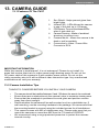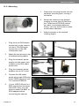
1
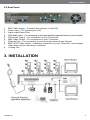
SVAT ELECTRONICS
now you can see
Web Ready 16CH DVR System
w/ 16 Outdoor Night Vision CCD Color Cameras
COMPLETE SYSTEM
INSTRUCTION MANUAL
Version 1.0
Model#
CLEARVU4
www.svat.com
SVAT ELECTRONICS
now you can see
!IMPORTANT! PLEASE READ!
NEED
HELP?
DO NOT RETURN THIS
PRODUCT TO THE STORE
Please contact a SVAT customer support representative first regarding any
additional information on product features, specifications or help with set-up.
Please contact us via one of the methods below:
Email:
[email protected]
Online live web chat:
Visit www.svat.com
Toll free telephone:
1.866.946.7828
Toll free fax:
1.888.771.1701
For more product information visit www.svat.com
Note: This is manual version 1.0 for this product, you may find updated versions by visiting our
website.
CLEARVU3
SPARTAN4
www.svat.com
2
SVAT ELECTRONICS
now you can see
PRODUCT WARRANTY & REGISTRATION
Please keep a copy of your Receipt/Order
Confirmation to verify your 1-Year Warranty
We take quality very seriously. This is why all of our products come with a one year
warranty from the original purchase date against defects in workmanship and materials.
If you have warranty or support issues please contact us using any of the following methods:
SVAT Electronics USA
2315 Whirlpool St., Unit 333
Niagara Falls, New York
USA 14305
SVAT Electronics Canada
4080 Montrose Road
Niagara Falls, ON
Canada L2H 1J9
Phone: 866.946.7828
Fax: 888.771.1701
Email: [email protected]
Website: www.svat.com
Warranty Terms
1. SVAT products are guaranteed for a period of one year from the date of purchase against defects in
workmanship and materials. This warranty is limited to the repair, replacement or refund of the purchase price
at SVAT’s option.
2. This warranty becomes void if the product shows evidence of having been misused, mishandled or tampered
with contrary to the applicable instruction manual.
3. Routine cleaning, normal cosmetic and mechanical wear and tear are not covered under the terms of
this warranty.
4. The warranty expressly provided for herein is the sole warranty provided in connection with the product itself
and no other warranty, expressed or implied is provided. SVAT assumes no responsibilities for any other
claims not specifically mentioned in this warranty.
5. This warranty does not cover the shipping cost, insurance or any other incidental charges.
6. You MUST call SVAT before sending any product back for repair. You will be given a Return Authorization
number. When returning the product for warranty service, please pack it carefully in the original box with all
supplied accessories, and enclose your original receipt or copy, and a brief explanation of the problem
(include RA #).
7. This warranty is valid only in Canada and the continental U.S.A.
8. This warranty cannot be re-issued.
CAUTION
RISK OF ELECTRIC SHOCK, DO NOT OPEN
TO REDUCE THE RISK OF ELECTRIC SHOCK, DO NOT REMOVE THE COVER (BACK).
NO USER SERVICEABLE PARTS INSIDE. REFER SERVICING TO QUALIFIED SERVICE PERSONNEL.
Graphic Symbol Explanation
The lightning flash with arrowhead symbol, within an equilateral triangle, is intended to alert the
user to the presence of insinuated “dangerous voltage” within the product’s enclosure that may be
of sufficient magnitude to constitute a risk of electric shock to persons.
The exclamation point within an equilateral triangle is intended to alert the user to the presence
of important operating maintenance (servicing) instructions in the literature accompanying the
appliance.
CLEARVU3
www.svat.com
SVAT ELECTRONICS
now you can see
TABLE OF CONTENTS
1. WHAT IS INCLUDED...................................................................................... 1
2. BUTTON FUNCTIONS AND CONNECTIONS.................................................................1
2.1 Front Panel . .......................................................................................... 1
2.2 Rear Panel............................................................................................. 2
3. INSTALLATION............................................................................................... 2
3.1 Camera Installation................................................................................ 3
3.2 Monitor Installation................................................................................. 3
3.2 Audio Installation.................................................................................... 3
4. POWER TO DVR............................................................................................ 4
5. DVR OPERATION........................................................................................... 5
5.1 Live Mode............................................................................................... 5
5.2 Record Mode.......................................................................................... 7
5.3 Playback Mode....................................................................................... 8
5.4 Search.................................................................................................... 9
6. MENU SETUP DESCRIPTION..................................................................... 10
6.1 Eight/ Sixteen Camera Mode Rescan...................................................11
6.2 DATE/ TIME SETUP.............................................................................11
6.3 Camera Setup...................................................................................... 12
6.3.1 Edit Camera Title 1-8.................................................................. 12
6.3.2 Edit Camera Title 9-16................................................................ 13
6.3.3 Video Adjust................................................................................ 13
6.3.4 Motion Detection......................................................................... 14
6.4 Record Setup....................................................................................... 15
6.5 Schedule Setup.................................................................................... 16
6.6 Hard Disk Setup................................................................................... 17
6.7 CF Card Setup..................................................................................... 17
6.8 OTHERS.............................................................................................. 19
6.8.1 Password.................................................................................... 20
6.8.2 Buzzer......................................................................................... 20
6.8.3 Relay Output (Advanced users).................................................. 21
6.8.4 Alarm Input (Advanced users)..................................................... 22
6.8.5 Sequence Dwell Time................................................................. 23
6.9 Factory Default..................................................................................... 23
7.DVR NETWORKING GUIDE.......................................................................... 24
7.1 Introduction.......................................................................................... 24
7.2 Prepare Your Computer....................................................................... 25
7.3 Prepare Your DVR................................................................................ 26
7.4 Connect To The Internet....................................................................... 27
7.5 Find Your External IP............................................................................ 29
7.6 Forwarding Outside Your Network....................................................... 30
7.7 Finalizing The Set-Up........................................................................... 33
7.8 Additional Troubleshooting................................................................... 34
CLEARVU4
SVAT ELECTRONICS
now you can see
8. FUNCTION SETUP....................................................................................... 35
8.1 Main Display......................................................................................... 35
8.1.1 View............................................................................................. 36
8.1.2 Image Recording......................................................................... 36
8.1.2.1 Save As JPEG:................................................................ 37
8.1.2.2 Save As AVI:.................................................................... 37
8.1.2.3 DVR Control.................................................................... 37
8.2 Advanced Network Setup............................................................... 39
8.2.1 Advanced Network Setting ................................................ 39
8.2.2 User Setup......................................................................... 40
9. DVR TROUBLESHOOTING......................................................................... 41
10. NETWORK INSTALLATION ...................................................................... 42
11. HARD DISK INFORMATION....................................................................... 42
12. APPENDIX.................................................................................................. 42
13. CAMERA GUIDE........................................................................................ 43
13.1 Features Of The CV67....................................................................... 43
13.2 Camera Installation Tips..................................................................... 43
13.2.1 Mounting................................................................................... 44
13.2.2 Troubleshooting......................................................................... 45
14. SPECIFICATIONS....................................................................................... 45
CLEARVU4
SVAT ELECTRONICS
now you can see
1. WHAT IS INCLUDED
1 10ft RCA to RCA
(male) A/V Wire
16 Indoor/Outdoor Night 16 Camera Mounts w/
Hardware
Vision CCD Cameras
1 DVR (320GB HDD)
18 RCA to BNC
Connectors
Software CD
16 x 60ft 4 PIN DIN
to RCA (male)Video/
Power Wires
10ft RJ45
Ethernet Cable
1 RCA Female to
3.5mm (male)
A/V Wire
•1 Power Adapter for DVR
•Online/ Toll Free Support
•Instruction Manual
•Quick Start Guide
•1 Year Warranty
•16 Power Adapters
for Cameras
2. BUTTON FUNCTIONS AND CONNECTIONS
2.1 Front Panel
1
2
3
4
17
5
6
7
8
9 10 11 12 13 15
14
1.
2.
3.
4.
5.
6.
7.
8.
9.
10.
11.
12.
13.
14.
15.
16.
17.
18.
16
18
LED Indicators (Alarm/Play/HDD/Record)
Removable/Lockable HDD Casing: 3.5” IDE HDD
Camera
Channel Select (1-16)
1
Record Button
6
8
Stop Button
9
5
4
7
Play2 Button
3
Pause Button
Split Button – Switch between Full Screen/ Quad Screen/ 9-Split Screen
Auto Sequencing Button – Automatically cycle through all the camera channels
Search Button – Quickly search your recorded footage by date and event.
Menu Button
Exit/Info Button – Return to the previous menu/view system information
Enter/Display Button – Confirm selection/show or hide onscreen display
CF Card Slot
Left Button – Change values in the menu screen/rewind
Right Button – Changes values in the menu screen/fast forward
Up Button – Navigate the onscreen menu/change camera channels
Down Button – Navigate the onscreen menu/change camera channels
CLEARVU4
1
2
1
4
5
6
8
7
9 10 11 12 13
14
18
SVAT ELECTRONICS
now you can see
2.2 Rear Panel
1
2
3
4
5
6
8
7
9
1.
2.
3.
4.
5.
6.
7.
8.
BNC Video Inputs – Connects the cameras to the DVR
Power Input – DC power input (12V)
Alarm Input/Output Port
RCA Audio Input – For connecting a microphone/audio supported camera (not included)
RCA Audio Output – For connection to your TV/monitor
BNC Video Output – For connection to your TV/monitor
Ethernet Port – For connection to your local area network and Internet
BNC SPOT Video Output – Additional connection to your TV/monitor, only displays
video when motion recording is activated
9. Cooling Fan
3. INSTALLATION
CLEARVU4
2
SVAT ELECTRONICS
now you can see
3.1 Camera Installation
1. Plug the 4 pin DIN female connection on the camera into the 4 PIN DIN
male connection on the 60ft video/power wire.
2. Match the two arrows on top of both connecting cables.
3. Plug the camera’s power supply into the power jack located on the 60ft
video/power wire.
4. Plug the camera’s power adapter into an AC outlet.
5. Connect the 60ft video/power wire’s male RCA plug to the VIDEO IN port
of your TV/monitor/VCR/DVR.
6. If your VIDEO IN port is a BNC connection (common with DVR units), you
will need to attach the BNC to RCA adapter before connecting the camera.
3.2 Monitor Installation
1. Connect an RCA male wire (not included) to the VIDEO OUT Monitor port on the DVR.
Plug the other end of the RCA wire to the RCA VIDEO IN port on the TV/monitor.
2. For motion activated viewing (SPOT), connect an RCA male wire (not included)
to the VIDEO OUT SPOT port on the DVR. Plug the other end of the RCA wire
to the RCAVIDEO IN port on the TV/monitor. Note that the video will only be
displayed when MOTION or ALARM recording is triggered.
3.2 Audio Installation
1. If you have an audio supported camera or microphone with an RCA Audio
Out connection, you may connect it to the Audio In port on the DVR.
2. Connect an RCA audio wire (not included) to one of the Audio Out ports on
the DVR.
3. Connect the other end to the Audio In port of your TV/monitor/speaker.
CLEARVU4
3
SVAT ELECTRONICS
now you can see
4. POWER TO DVR
1. Insert the power supply wire into the rear DC 12V Port on the DVR.
2. Insert the power cord into the power supply.
3. Plug the power cord into a power outlet. We recommend using a surge protected
power bar and/or Uninterrupted Power Supply (UPS) backup. To turn the DVR
on and off, use the power switch on your UPS or power bar. This DVR does not
have a power switch. This is for your security and helps to prevent users from
accidentally turning the DVR off.
The DVR will power on and you will see a boot screen. After the DVR initializes your
cameras should be displayed and recording will begin immediately.
Important notes before operation
1. To power off the DVR, make sure the DVR is not recording to prevent file
corruption. If on manual record, press STOP to stop recording and wait for the
REC light to turn off before you power off the DVR. If in schedule record, press
MENU and enter the password to enter the menu screen. When the record light
turns off, you can power off the DVR.
2. The default password is 12345678.
3. This DVR does not support HDD hot swap. To prevent damage, please enter
the main menu to stop all HDD activities, then power-off the device before
replacing the hard disk.
4. After power-on, the DVR auto detects the video system (NTSC/PAL) of the first
camera connected. When no camera has been connected, the video system
will be the same as the previous setup.
5. After power-on the system auto enters 9-split screen mode, and continues with
the previously setup recording schedule (auto resume recording)
CLEARVU4
4
SVAT ELECTRONICS
now you can see
5. DVR OPERATION
5.1 Live Mode
1. Press the “DISP” button to turn the onscreen display ON or OFF. The onscreen
display shows the channel, date, and time.
2. Press the “INFO” button to display system information and configuration.
3. When the hard disk information icon turns to red, this indicates that the hard drive
is full. To avoid this situation, set the DVR recording mode to OVERWRITE.
4. Press the channel buttons to switch between full screen camera views.
(CH1 – CH16).
5. Press the “SPLIT” button to switch between “Full Screen/Quad Screen/
9-Split Screen”.
6. Press the “SEQ” button to turn Sequence Mode on or off. Full screen channel
auto sequence will skip the channels that show video loss (i.e. the cameras that
are unplugged or not powered on).
7. When video loss occurs, a video loss message will be shown on the screen.
8. During an alarm triggered event the corresponding channel name will be
changed to the color red.
9. During a motion triggered event the corresponding channel name will be
changed to the color red and display “M”.
10. When an alarm event occurs, the SPOT monitor (when plugged into the SPOT
Out port) will immediately switch to the full screen view of the channel that has
been triggered by an alarm event, and will then return to previous channel
switching status.
11. Live monitoring operations have no effect on recording functions.
CLEARVU4
5
SVAT ELECTRONICS
now you can see
System Information: Screen shot
CLEARVU4
6
SVAT ELECTRONICS
now you can see
5.2 Record Mode
Quick Glossary of Recording Terms:
Manual Record: This is the simplest of recording modes. Just press record to record video
from your cameras. The system will continue recording until you press stop.
Continuous Record: This is a schedule record mode that allows you to specify what hours
of the day you would like to record. The system will continue to record for those specified
hours. During this time, you cannot press stop to halt recording. You must press menu.
Motion Record: This is a schedule record mode that allows you to specify which hours of
the day you would like to record when movement is detected. After motion is detected, the
system will record for a duration that you specify. During this time, you cannot press stop to
halt recording. You must press menu.
Alarm Record: This is a special recording method that requires you to have alarm sensors
wired in to the DVR. You must buy these alarm sensors separately from a 3rd party, and
SVAT does not offer support on motion sensors. This feature is for advanced users only. If
you have alarm sensors wired correctly, the alarm record function will allow you to specify
which hours of the day you want to record when your alarm sensor is triggered. After your
alarm is triggered, the system will record for a duration that you specify. (During this time, you
cannot press stop to halt recording. You must press menu.)
1.
Manual Record: Under monitoring mode, press the “REC” button to enable all (CH1
– CH 16) camera recordings, and the “STOP” button to stop manual recording.
2. When schedule recording (ALARM/ MOTION DETECTION/ CONTINUOUS
RECORD) has been activated, recording can not be stopped by pressing the
“STOP” button. You must enter the menu screen to disable recording.
3. After entering playback mode or menu setup, when the correct password has
been entered, all recording activities will stop. When exiting playback mode or
menu setup, and schedule recording has been switched on, schedule recording
will auto resume.
4. At power on after a power loss, the system auto returns to the recording mode
scheduled before power-loss.
CLEARVU4
7
SVAT ELECTRONICS
now you can see
5.3 Playback Mode
1. When pressing the PLAY button and when the playback password is set to “ON”,
the system will request to enter a password. When the correct password has
been entered, all recording activities will stop and playback mode will begin.
2. Press the “PLAY” button to play back starting from the previous playback end
time (continues from where you left off).
3. Press the “DISP” button to switch on/off the channel, date, and time message display.
4.
5.
6.
7.
8.
9.
Press the “INFO” button to switch on/off the system information display.
Press the channel buttons to play back a camera channel in full screen (CH1 – CH16).
Press the “SPLIT” button to switch to “Full Screen/ Quad Screen/ 9-Split Screen”.
The SEQ button does not function during playback.
Press the “PAUSE” button under normal playback to pause.
During pause status, hold the “LEFT” button to step rewind playback, and the
“RIGHT” button to step forward playback.
10. During normal playback, press the “LEFT” button to adjust the rewind playback
speed (x1/ x2/ x4/ x8/ x16/ x32/ x64 ), and the “RIGHT” button to adjust the
forward playback speed (x1/ x2/ x4/ x8/ x16/ x32/ x64). Press the “PLAY” button
to return to normal speed and the “PAUSE” button to pause.
11. Connect the audio output to your TV/monitor/speaker input (using an RCA wire)
to enable audio playback.
12. Press the “STOP” button to stop playback and return to live monitoring mode or
schedule record mode.
CLEARVU4
8
SVAT ELECTRONICS
now you can see
5.4 Search
1. When you press the SEARCH button and the playback password is set to “ON”,
the system will request password entry. When the correct password has been
entered, all recording activities will stop.
2. Press the SEARCH button for quick search by date and time. Press the ENTER
or PLAY button to enter 9-split screen display.
3. YEAR/ MONTH/ DAY/ HOUR:
•White Index Bar: No recorded data available under this date period.
•Green Index Bar: Recorded data available under this date period.
4. MINUTE:
•White Color Bar: No recorded available under this time period.
•Red Color Bar: Manual recorded data, motion detection recorded data, andalarm recorded data is available under this time period.
•Blue Color Bar: Schedule recorded data is available under this time period.
5. Use the “UP/ DOWN” buttons to move the cursor to the desired item (YEAR/
MONTH/DAY/HOUR/MINUTE), use the “LEFT/ RIGHT” buttons or drag the index
bar to make changes to the setup.
6. After setup has been completed, press the “ENTER” button to enter play mode,
or the “EXIT” button to return to live monitoring mode.
CLEARVU4
9
SVAT ELECTRONICS
now you can see
6. MENU SETUP DESCRIPTION
The password is requested after the “MENU” button is pressed.
1. In order to enter the main menu, the password entered must be correct. After
entering the main menu all recording activities will stop.
2. Default Password: 12345678 (CH1~CH16 represents number 1~16).
CLEARVU4
10
SVAT ELECTRONICS
now you can see
6.1 Eight/ Sixteen Camera Mode Rescan
1. When only 8 cameras has been connected (whether it is the first 8 or last 8
cameras), the system will enter 8-ch monitoring display mode. For all cameras
to be displayed you will have to reboot the DVR or enter the menu to re-detect
16-ch monitoring display mode.
2. When more than 8 cameras are connected, the system will enter 16-ch
monitoring display mode, and when disconnecting the cameras leaving only 8
cameras connected, the system will have to reboot or enter menu to re-detect
8-ch monitoring display mode.
3. Under 16-ch display mode, please avoid mix application on corresponding
channels (corresponding channels: 1-9, 2-10, 3-11,…, 8-16) of b/w and
color cameras; otherwise color cameras may be auto changed to b/w mode.
Therefore, connecting or disconnecting the cameras, the system will have to
reboot or enter menu to re-detect the monitoring display mode.
6.2 DATE/ TIME SETUP
DATE FORMAT (Three Types of Date Format Setup) :
1. Y/M/D: Year/ Month/ Day
2. M/D/Y: Month/ Day/ Year
3. D/M/Y: Day/ Month/ Year
CLEARVU4
11
SVAT ELECTRONICS
now you can see
6.3 Camera Setup
6.3.1 Edit Camera Title 1-8
1.
2.
3.
CLEARVU4
Maximum 8 character titles.
Move the cursor to the desired camera number by using the
“UP/DOWN” buttons.
Move between the characters of the camera title by using the “LEFT/ RIGHT”
buttons and use “UP/ DOWN” buttons to edit the camera title (letters A-Z, numbers
0-9 or blank spaces).
12
SVAT ELECTRONICS
now you can see
6.3.2 Edit Camera Title 9-16
6.4.2 VIDEO ADJUST
Adjustable brightness, contrast, saturation, and hue for 1 –16 CH videos.
6.3.3 Video Adjust
Adjustable brightness, contrast, saturation, and hue for 1 – 16 CH videos.
CLEARVU4
13
SVAT ELECTRONICS
now you can see
6.3.4 Motion Detection
You can use these settings to adjust the area and sensitivity of motion detection on
each camera channel. These settings are important if you are using motion activated
recording, because if adjusted correctly, they can help prevent false triggering of
motion recording.
1.
Channel – Select the camera channel in which you would like to make changes
2. Set Detection Area – Select this setting to enter a grid screen for the selected
camera channel. In this screen you can set the areas in the camera’s view
that you want to enable or block motion detection in. For example, if there
are cars constantly driving by in an area on your camera, you can block
that area from detecting motion. Use the directions below to set up motion
detection areas:
Area Block Color:
• Grey: Detection Block. These areas will be detected
• Transparent: Non-Detection Block.
• Green: Flashes when motion on the camera is being detected.
Use the green flashes to determine where motion is consistently being detected, and
then make sure to set the motion detection area to exclude these areas from motion
detection. Follow the directions below:
•
•
•
•
•
CLEARVU4
Press “SEARCH” button to enable whole detection area.
Press “MENU” button to disable whole detection area.
You can set up a maximum of 3 separate detection areas (Detection areas may overlap):
Press the” UP/ DOWN/ LEFT/ RIGHT” buttons to setup the starting point of
the detection area.
Press the “ENTER” button to confirm the starting point of the detection area.
14
SVAT ELECTRONICS
now you can see
•
•
Press the “UP/ DOWN/ LEFT/ RIGHT” buttons to drag the window and set
the ending point of the detection area.
Press the “ENTER” button to confirm the ending point of the detection area.
3. Sensitivity: The blue bar shown on the Motion Detection screen indicates
the motion variation of the detection window. When the amount of motion
detected exceeds the preset sensitivity threshold, it triggers motion
detection recording. For example, if there is slight movement in your
camera’s view (e.g. curtains blowing, shadows) you can decrease the
sensitivity of that camera channel to avoid false triggering of motion record.
6.4 Record Setup
1.
2.
3.
QUALITY: LOW/ MEDIUM/ HIGH
AUDIO:
•ON: Audio recording enabled.
•OFF: Audio recording disabled.
DISK FULL:
•Overwrite: When the hard disk is full the system overwrites your oldest recorded footage (recommended).
•Stop: When the hard disk is full the system stops recording (message will
be displayed).
4. POST ALARM: Recording time after an event (Alarm/ Motion Detection) has
been triggered.
5. MANUAL: Set frames per second (FPS) for manual recording.
6. CONTINUOUS: Set FPS for schedule continuous recording.
7. MOTION DETECT: Set FPS for schedule motion detection recording.
8. ALARM: Set FPS for schedule alarm recording (if you have alarm sensors
wired into the DVR).
9. DEFAULT: Reload the factory default setting.
CLEARVU4
15
SVAT ELECTRONICS
now you can see
6.5 Schedule Setup
Use this menu to set up a 24 hour recording schedule. Specify which hours to record
when motion is detected, and when to record continuously or not at all.
The recording schedule is based on a 24 hour clock that goes from 0~24. Using the
directional arrows, move the cursor to the hour of the day you would like to change,
and adjust the letter to the one that represents the type of recording you would like. For
example, if you want to record only when motion is detected at 12:00 PM, move the
cursor to the 12, and use the arrows to change the letter to “M”. All types of recording
are listed below along with their corresponding letter:
1.
2.
3.
4.
5.
CLEARVU4
C: Continuous Recording
M: Motion Detect Record
A: Alarm Recording (advanced users only)
- : None (no recording will occur)
* : All (all types of recording are activated)
Record Mode Priority:
Manual Record>Alarm Record>Motion Detection Record>Continuous Record
16
SVAT ELECTRONICS
now you can see
6.6 Hard Disk Setup
1. Displays the hard disk total capacity and the remaining capacity.
2. Displays the start and end date of the recorded material and when no recorded
materials are available, current date is displayed.
3. FORMAT: Format the HDD. Warning: This will erase all your recorded footage.
6.7 CF Card Setup
1.
2.
3.
4.
CLEARVU4
CF TOTAL CAPACITY: Total Capacity
CF REMAIN CAPACITY: Remaining Capacity
CF CARD COPY: Copy the selected file to the CF card.
FORMAT: Delete all data stored in the CF card.
17
SVAT ELECTRONICS
now you can see
6.7.1 CF Card Copy
Use this feature to backup your footage onto CF card (CF card reader required to view on
a computer). Note that only one camera channel can be recorded at a time.
1.
2.
3.
4.
CH: Selectable 1 -16 camera option.
AUDIO: Specify whether to record audio or not.
BEGIN/END: Specify the start and end time of the desired video clip.
COPY: Select “COPY” to start copying to your CF card.
*When the data size selected exceeds the storage capacity of the CF card, it will start
copying from the beginning and stop when the CF card is full. Each channel and event
generates a different AVI file. Windows Media Player supports AVI file playback (File size
is 720X240. When using a computer to playback, the video aspect ratio is not 1:1, please
use a player with adjustable video aspect ratio).
CLEARVU4
18
SVAT ELECTRONICS
now you can see
6.8 OTHERS
1. PASSWORD:
ON: Enable password protection, password is required before entering the
main menu.
OFF: Disable password protection, password will not be required before entering
the main menu.
2. KEY STOP BUZZER/ RELAY: Use this option if you have an external relay
device attached (advanced users). When the buzzer or relay device is triggered
by an event, enabling this setting will allow you to press any key to deactivate.
3. COLOR BAR: By using the color bar, the user may adjust the color of the monitor.
4. LANGUAGE: Select the desired language.
CLEARVU4
19
SVAT ELECTRONICS
now you can see
6.8.1 Password
1. Search/ Playback Password: Specify whether the search or playback mode is
password protected. When password is stored on the CF card, after inserting
the CF card the password will not be requested by the system.
2. Default Password: 12345678 (CH1~CH16 represents number 1~16).
3. Press the “ENTER” button to enter new password, confirm settings, and press
“EXIT” button to exit.
6.8.2 Buzzer
BUZZER:
ON: Buzzer is enabled.
OFF: Buzzer is disabled.
CLEARVU4
20
SVAT ELECTRONICS
now you can see
Period: Duration time of the buzzer output.
Buzzer event includes the following:
1.
2.
3.
4.
5.
KEY PRESSED: Disable/Enable beeping when keys are pressed.
MOTION DETECTION: Disable/Enable motion detect alarm
ALARM: Disable/enable motion sensor alarm.
VIDEO LOSS: Disable/enable video loss alarm
DISK FULL: Disable/enable disk full alarm.
6.8.3 Relay Output (Advanced users)
The installation of any relay output alarm is optional and SVAT cannot offer technical
support on such alarms. Contact the alarm sensor manufacturer for more information.
RELAY OUTPUT: A relay output can be connected to an external sounding device or
warning device.
Two Types (NO/ NC) of Relay Output Setup:
ON: Relay output enabled.
OFF: Relay output disabled.
PERIOD: Duration time of the relay output.
Relay output event includes the following:
1. VIDEO LOSS: Triggered by video loss.
2. MOTION DETECTION: Triggered by motion detection.
3. ALARM: Triggered by external alarm.
CLEARVU4
21
SVAT ELECTRONICS
now you can see
6.8.4 Alarm Input (Advanced users)
The installation of any external alarm sensor is optional and SVAT does not offer technical
support on such alarms. Contact the alarm sensor manufacturer for more information.
Sensor Type
NC → Normal Close (NC) Alarm
Setup NC (Normal Close), the alarm will be triggered during NC status.
NO → Normal Open (NO) Alarm
Setup NO (Normal Open), the alarm will be triggered during NO status.
All
+ (EACH): Alarm input can be individually setup to NC or NO.
- (DISABLE): Disable alarm input can be individually setup.
C: All alarm input is setup to NC.
O: All alarm input is setup to NO.
CLEARVU4
22
SVAT ELECTRONICS
now you can see
6.8.5 Sequence Dwell Time
1. SEQUENCE: Specify how long each camera will be displayed when in
sequence mode.
2. SPOT MONITOR: Specify how long video will be displayed on the SPOT
monitor when motion is detected.
3. SPOT MONITOR ALARM: Specify the dwell time for the spot monitor alarm.
6.9 Factory Default
To return to factory default settings, select the “YES” option and then press “ENTER” to
load the factory defaults. Press “EXIT” to exit.
CLEARVU4
23
SVAT ELECTRONICS
now you can see
7.DVR NETWORKING GUIDE
7.1 Introduction
Congratulations on taking a step forward in protecting your valued possessions. Now that
you have your video security system in place, connecting it to the internet will allow you to
view what’s important to you with ease. You will learn about your product and will see that
you can do this on your own. The following is a step by step instruction manual on how to
connect your system to the internet. You will be able to view your DVR and even watch
previously recorded footage with the touch of a button.
NOTE: This guide was created using a cable modem and some procedures will be slightly
different depending on your hardware. If you are using a DSL modem, you may need to
enter your PPPoE settings into the DVR (User name and password provided by your ISP.)
For more information refer to section 9.2 of the user manual.
Before you start lets make sure that you have everything you need to do this properly. You
should have these ready and connected before beginning:
•
•
•
•
•
DVR connected to a router
Router connected to the internet. In order for this DVR system to connect to
the internet, it must be connected to a router. If you are using a DSL internet
connection the setup process is much easier if you use modem with a router
integrated in it as this will help avoid any problems connecting your DVR. Please
write down the model # of your router in the important information section.
A PC laptop or computer that is connected to the router so you can make the
necessary changes. This system is not Mac compatible. Your computer should
have the following specifications:
Internet Explorer Version 5 or higher. If you do not have this program,
please go to www.download.com and get an updated version. You can check
your version of Internet Explorer by opening the program. Go to the top menu
selection and in the Help menu options, choose About Internet Explorer. The
version will be displayed.
A valid and fully updated version of Windows XP (minimum).
Important Information
Please fill in the information you receive during this installation in the areas below:
Your router manufacturer:
Your router model #:
Example: D-Link
Example: DI-524
Router IP:
Example: 192.168.1.1
DVR IP:
Example: 192.168.1.101
Port #: ______
Example: 80
External IP:
Example: 14.14.243.113
DynDNS Username:
Example: myname1234
DynDNS Password:
Example: 123ABC
DynDNS Domain Chosen:
Example: dyndns.org
Sign-In URL:
Example:myname1234.
CLEARVU4
dyndns.org
24
SVAT ELECTRONICS
now you can see
7.2 Prepare Your Computer
Following these steps will allow your computer to view the video.
Before starting to set-up your network connection, you have to be sure that your computer is able to
view the footage from the DVR. If you are running Windows XP, you will most likely have
this pre-installed.
NOTE: You will need to do this to any computer that you want to view the footage from.
1. Open Internet Explorer. Go to the
drop down menu in the TOOLS area
and select INTERNET OPTIONS. A
screen will open.
2. Select the SECURITY tab, then click on
the CUSTOM LEVEL button in this tab.
3. Change the ActiveX settings to the
ones seen in the images.
• Download signed ActiveX
controls: PROMPT
• Download unsigned ActiveX
controls: PROMPT
• Initialize and script ActiveX controls
not marked as safe: PROMPT
• Run ActiveX controls and
plug-ins: ENABLE
• Script ActiveX controls marked safe
for scripting: ENABLE
If it is an option:
•
Allow automatic prompting for file and
code downloads: ENABLE
NOTE: If you do not have ActiveX installed
and the previous step did not download
it, go to www.download.com and
search for ActiveX. Download the
ActiveX Download Control.
Your computer is now able to view the feed from the DVR.
CLEARVU4
25
SVAT ELECTRONICS
now you can see
7.3 Prepare Your DVR
Next we will set up the DVR to connect to the internet and allow you to view online.
1. Place the CD-ROM that was included with the DVR system into your computer’s
CD-ROM drive. If your computer does not automatically open the CD folder, go
to Start/My Computer and double-click on the CD-ROM icon.
2.
Drag and drop the IPEDIT.EXE program onto your desktop. This program will
give you the information needed to find your DVR’s IP address (unique location
on your network).
3. Open IPEDIT.EXE from your desktop. Depending on your firewall settings,
a warning message may appear asking if you want to block or unblock this
program. Click Unblock.
4. Click on the UPDATE button. In the top left area of the program window you
should see a set of numbers. This is the IP address of your DVR. Write it down
in the information area of this manual listed as ROUTER IP.
5. Open up Internet Explorer. In the Address bar, enter your DVR’s IP address found
in Step 4 followed by a space, a colon and the port number. This DVR’s default port
number is 80. Your IP address should look something like this: 192.168.0.1 :80
Some versions of Internet Explorer will not work with a space in the address bar.
If this is the case, try it without the space. eg: 192.168.0.100:80
6. If entered successfully a window will open
up with a login screen. The default USER
NAME is admin. The default PASSWORD
will be 1234.
CLEARVU4
26
SVAT ELECTRONICS
now you can see
7. The first time you logon to the DVR, an ActiveX Installation window will appear.
Install the ActiveX control.
7.4 Connect To The Internet
If your Internet connection is DSL (a broadband connection that comes through your
phone line) you may need to configure PPPoE settings in your DVR. If you do not
know what type of broadband connection you have, contact your internet service
provider. Ask your ISP if your internet connection is cable or DSL.
If you have cable: Skip the DSL section below and continue with the Port Forwarding Section.
If you have DSL:
You need your DSL user name and password. You may be able to find it in the documentation that came with your DSL modem. If not, please call your Internet Service Provider to acquire it.
1.
2.
3. 4. 5. 6. Click on the CONFIGURATION button in the DVR browser.
Under Remote IP Assignment, enter your DSL user name in the User Name box.
Enter your DSL password in the Password box.
Scroll to the bottom
Click the “Reboot” button.
Power off the DVR and power it back on to confirm the changes. The changes
will not take effect until you restart the DVR.
7. Follow the steps listed in the Port Forwarding section
PORT FORWARDING
Port forwarding is a necessary step that opens a path on your home/business network to
allow you to view your DVR video feed from outside your network (over the internet).
There are hundreds of makes and brands of routers on the market and these instructions
have been made using a D-Link router (Model DI-524). If you have a router that is different
than shown, please visit www.portforward.com and go to the link marked GUIDES. Once on
this page, go to the link marked Port Forwarding Guides by Router. Find your router make
and model in the list of links and click on it. You will see a list of various applications. Find
a link for any DVR or IP camera and click on it. Follow the instructions but make sure you
forward the correct port number (the port number assigned to your DVR. The default port
number is 80. )
The steps for your router will be similar to the following.
These instructions have also been created without a firewall in place. If you have a firewall,
please consult a computer technician.
CLEARVU4
27
SVAT ELECTRONICS
now you can see
NOTE: Your router may require a user name and password. If you do not know it, ask
the person who configured your network. Portforward.com will provide you with each
router’s default user name and password.
D-LINK ROUTER
You will need to enable the ports by locating the port range forwarding screen. With some
D-LINK routers the port forwarding screen is located within the Applications & Games or
Filters tab; in others it is located in the Advanced Tools tab.
1. Open your web browser. Enter the ROUTER IP address in the address bar as shown below and
press ENTER.
2. Enter the user name admin. Leave the password blank followed by pressing the OK
button (unless you have set up a user name and password for your router)
3. Select the Advanced tab.
CLEARVU4
28
SVAT ELECTRONICS
now you can see
4.
•
•
•
•
•
Select the Virtual Server tab.
Enable the Virtual server
In the Name field type in “DVR”
In the Private IP field enter the DVR’s IP address.
In the Protocol field, select Both (This will enable both TCP and UDP).
In the Private port enter the port number you need to forward. By default this DVR is set
to port 80. Use port 80 unless you have a reason to change the DVR to another port (not
recommended).
• In the Public port re-enter the port number you entered in the private port field (e.g. 80).
• Select the Schedule to Always.
• Ensure that the Virtual Server (or forwarding that is being set-up) is set to ENABLED.
When complete, select the Apply button located at the bottom of the page to save your
changes. Port forwarding is now complete!
7.5 Find Your External IP
Now you will need to find your external IP address. This will be the address you will be
entering in order to access the DVR from outside your network (over the internet).
There are many ways to find your external IP address. The simplest way is to go to http://
www.whatsmyip.org. This site will display your external IP address in the top portion of the
screen.If you go to http://www.portforward.com, it will also display this IP address. Write it
down on the second page marked EXTERNAL IP.
Test Your External IP
Now that you know your external IP address, you can perform a test to ensure your DVR is
accessible from outside your network (over the internet).
1. Open Internet Explorer, and in the address bar type in the EXTERNAL IP address,
followed by a colon and your port number (default is port 80). It should similar to the
following 2 examples:14.14.243.113 :80 OR 14.14.243.113:80
CLEARVU4
29
SVAT ELECTRONICS
now you can see
2. Press ENTER, and your DVR’s login window should pop up. If it does not pop up, your
router is not properly forwarding the necessary port. This could be due to a number of
problems including incorrect settings, presence of a firewall, or a DSL modem that has
its own IP address.
If your DSL modem has its own internal IP address, it will not properly forward the
necessary port. You may have to configure PPPoE settings in the DVR to match the
settings provided to you by your Internet Service Provider (ISP). Consult your ISP for
more information. SVAT technical support cannot troubleshoot modems, since changing
these settings can potentially render your modem inoperable.
See section 9.2 Advanced Network Setup for PPPoE configuration instructions.
You should also check all your network connections and go through the above steps
again to make sure a configuration error was not made.
7.6 Forwarding Outside Your Network.
Port Dynamic DNS
This section will explain how to associate your IP address with an easy-to-remember URL (domain name)
1. Open Internet Explorer and type in www.dyndns.com
2. The instructions on creating a dynamic DNS may have changed since the writing of this
guide. Create a new account by clicking the link “Create Account”
3. Enter your preferred user name, email address, and password.
4. Do not worry about the optional information. Agree to the Terms of Service by checking
the boxes. Click Create Account.
CLEARVU4
30
SVAT ELECTRONICS
now you can see
5. Now check your email for the confirmation message. You will need to click the link in the
body of this message to activate your account. The message may take up to 24 hours
to arrive in your inbox. If you cannot find the message in your inbox, please check your
junk/spam mail folder.
6. When you click the link, a window will appear that displays “Account Confirmed.” Click
on the login link and enter the user name and password you created.
7. Click on the Services button located on the top menu
8. Click on the Dynamic DNS link
CLEARVU4
31
SVAT ELECTRONICS
now you can see
9. Click on the Get Started link located on the right menu
10.Type in a host name (subdomain name). We recommend you use your first name or
company name.
11. Choose a domain name from the dropdown menu. We recommend using the dvrdns.org suffix.
12. In the IP address field, type in your external IP address (it may also be shown below the field).
13.Leave all the rest of the options as-is, and click Create New Host.
14.Your dynamic DNS settings have been created.
CLEARVU4
32
SVAT ELECTRONICS
now you can see
7.7 Finalizing The Set-Up
Now you must associate your DVR with the DynDNS account you just created. This will
ensure that when your external IP address changes, your domain name (address in the
Internet Explorer Address Bar) will remain associated with your new IP address. This will
ensure that you will only need to type in your domain name in order to access your DVR,
whether you are inside or outside of your network:
1. Log-on to your DVR through your computer by using either the internal or
external IP address.
2. Click the CONFIGURATION button.
3. Under the “Network DVR Setup” window, scroll down to “DDNS Account Setting.”
4. Make sure the ENABLE button is selected.
CLEARVU4
33
SVAT ELECTRONICS
now you can see
5. Enter the username, password, and full domain name you configured at www.
dyndns.com.
Example:
UserName: myname
Password: mypassword
DomainName: myname.dvrdns.org
6. Click the OK button located in this section to save your configuration. Reboot
the DVR by powering it off and then on again to confirm the changes. You must
reboot the DVR any time a change is made in the configuration menu.
7. You should now be able to access your DVR simply by typing in your domain
name (i.e. myname.dvrdns.org)
Note:
If your router is set to automatically assign an IP address to your DVR (Dynamic/DHCP),
your DVR’s internal IP address may change if your DVR or router is rebooted. To resolve
this problem, you need to configure your router to forward to this new address (simply
replace the old private IP address with the new one). To avoid this problem all together, you
can set your router to Static LAN IP, which will assign the same IP address to the DVR every
time, even when the DVR or router is rebooted.
7.8 Additional Troubleshooting
I press play and nothing happens
You need to press STOP on the DVR first. This DVR can either record or view video
footage. It will not do both at the same time. Please make sure that you press STOP
before proceeding.
My browser keeps freezing
First make sure you have an up to date browser and that the proper ActiveX options are
selected. If they are, you may need to re-install your browser.
I can’t remember my DVR’s password
Call technical support to obtain the DVR’s master password
I can’t see at night with my IR night vision camera
These cameras are spec’d at 10-15ft in the dark. If you placed these cameras outdoors in
the open, the night vision will be reduced as there is nothing to reflect the IR emitted from
the camera. To help increase the viewing capabilities add additional lighting to the area.
The color is off on the camera
These cameras have been designed with a high resolution lens which allows you to see
crisp clean images. The best lighting for this system is by using incandescent lighting.
Other lighting effects will alter the color. You can adjust the color of the cameras in your
menu settings. (see 7.2.2)
CLEARVU4
34
SVAT ELECTRONICS
now you can see
NOTE:
When entering an external or internal IP address, the port number is required and should be in the
following format:
192.168.0.100 :80 OR 192.168.0.100:80 (some browser versions require a space, some do not)
8. FUNCTION SETUP
8.1 Main Display
Optimal browsing resolution is 1024 x 768.
Live Display
Move the cursor inside the image range and right mouse click to display the following menu:
CLEARVU4
35
SVAT ELECTRONICS
now you can see
8.1.1 View
Two types of display methods:
1. Re-sizable: Adjustable image size.
2. Actual size: The actual image size.
3. Status Bar: Reveals current status.
8.1.2 Image Recording
This mode allows you to save picture or video files from the DVR to your computer.
Image Recording Setup Display:
1. Save as JPEG: Save as picture file
2. Save as AVI: Save as AVI animation file
Note: To prevent asynchronous AVI recording both functions should not be
simultaneously selected.
CLEARVU4
36
SVAT ELECTRONICS
now you can see
8.1.2.1 Save As JPEG:
The following options allow you to customize how the jpeg image files are saved:
• No Limit: Unrestricted image storage (continuous jpeg saving)
• Number: Image storage according to number of frames. For example, if set to 50,
50 frames will be stored in 50 separate jpeg files.
• Save interval: Image storage according to one tenth of a second. For example,
if you enter 10, then one frame is stored per second. If you enter 50, then one
frame is stored every 5 seconds.
• Size: Image storage according to file size.
• Time: Image storage according to time. For example, if set to 60 seconds, the
system will capture jpeg files for 1 minute.
• Save Path: Specify the file path on your computer to save the jpeg files.
• Pre Name: Specify the prefix for the jpeg files, and they will be numbered in the
order in which they are captured. For example, setting the Pre Name to “DVR_”
will generate files starting with “DVR_1”, DVR_2” and so on.
8.1.2.2 Save As AVI:
•
•
•
•
•
•
•
•
•
No Limit: Unrestricted video storage (continuous avi recording).
Number: Video storage according to number of frames. For example, if set to 50,
50 frames will be stored per avi file.
Save interval: Video storage according to one tenth of a second. For example, if
you enter 10, then one file is stored per second. If you enter 50, then one file is
stored every 5 seconds.
Size: Video storage according to file size.
Frame Rate: Specify the frame rate of each avi file.
Time: Video storage according to time. For example, if set to 60 seconds, the
system will capture video for 1 minute.
Maximum Number of Frame in Each File: Specify the maximum number of frames
in each AVi file.
Save Path: Specify the file path on your computer to save the avi files.
Pre Name: Specify the prefix for the avi files, and they will be numbered in the
order in which they are captured. For example, setting the Pre Name to “DVR_”
will generate files starting with “DVR_1”, DVR_2” and so on.
8.1.2.3 DVR Control
1. CHANNEL
SELECT
Camera Select Button: CH1~8
2. REC
Manual Record Button
3. STOP
Stops manual recording and playback.
CLEARVU4
37
SVAT ELECTRONICS
now you can see
4.PLAY
Play Button
5.PAUSE
Pause Button
6. SPLIT
Full Screen/ Quad Screen/ 9-Split Screen
7.SEQ
Automatically cycle between cameras
8.SEARCH
Quick search of recorded videos
9.MENU
Change DVR settings
10.EXIT/INFO
Returns to Previous Menu/ System
Information Display Toggle/Confirm Button/
Message Display Toggle
12.ENTER/
DISP
Return to Previous Menu/ System Information
Display Toggle/ Confirm Button/ Message
Display Toggle
11.UP/DOWN/
REW/FF
Up Directional Button/ Channel Up Button/
Down Directional Button/ Channel Down
Button/Left Directional Button/ Right
Directional Button
Resolution Setting
• 120x160
• 320x240 (Pre-set Value)
• 640x480
Quality Setting
• High
• Middle
• Low (Pre-set Value)
Brightness/Contrast/ Saturation/
Sharpness
- : Min. Value
STD: Pre-set Value
+: Max. Value
The higher values are shown to the
right and descend in value as you go
to the left.
CLEARVU4
Configuration
Advanced Setup - this function can only
be adjusted by the administrator (i.e. the
user name must be admin).
Live Video
Back to live video display
Record
Please refer to 9.1.2 Image Recording
Snapshot
Press this button to capture one live image
and press “RIGHT” button to store the
image.
Audio
Live audio control “On/ Off” (Default: OFF).
38
SVAT ELECTRONICS
now you can see
8.2 Advanced Network Setup
Only “Admin” can select “configuration” (advanced setup).
8.2.1 Advanced Network Setting
1. LAN Setting: LAN IP address setting is the same as IPEdit.
2. DHCP: Select item “Automatically by DHCP” to get an IP address.
3. DNS Configuration (Advanced)
CLEARVU4
39
SVAT ELECTRONICS
now you can see
4. PPPoE: If you have an ADSL modem, you may need to set up PPPoE in order to
view your DVR from outside your network. You will need your login information. If you do not have it, please contact your Internet Service provider to provide you with the
login information.
5. Optional:
Send mail (about new IP) after connected should be selected if you want to receive
an email when your external IP address changes from your ISP. You will receive
an email at the receiver’s email address when the external IP address changes. If
you are unaware of the mail server or username settings contact your ISP for this
information.
6. HTTP Port: Select the port number (default is port:80)
8.2.2 User Setup
1. 2.
3. 4. 5. 6. 7.
Authentication: Choose whether or not a user name and password are required
Enter your user name in the User Name box.
Enter your password in the Password box.
Re-enter your password in the Confirm box.
Click the “Set Change” button.
Click the “Reboot” button.
Power off the DVR and power it back on to confirm the changes. The changes
will not take effect until you restart the DVR.
This section allows you (the administrator) to set up multiple user accounts so other
authorized users can access the DVR. These users will be able to view live display, record,
and capture images. However, they will not be able to change configuration settings. When
you have set up user accounts, be sure to write down the user name and password for each
account so you can provide the users with the appropriate login credentials.
Authorization: Specify whether authentication is needed to access the DVR. If you select
“No Need,” there is a possibility that unauthorized users may access your DVR.
New User/Change Password: Add user or change password (Max. users = 30).
Note: For best results, a maximum of 20 simultaneous users is suggested.
CLEARVU4
40
SVAT ELECTRONICS
now you can see
Delete User: Delete user account.
Current Users: Currently registered users.
Reboot: Restart the Network DVR.
Firmware update: Updates the firmware, if a new firmware version becomes available. Firmware
updates may be available at www.SVAT.com (advanced users only).
Restore factory default configuration: Click “Restore factory default configuration” to return to
factory default settings (Please restart the Network DVR after setup has been completed)
9. DVR TROUBLESHOOTING
Before calling technical support 1.866.946.7828, try the following troubleshooting tips:
Problem
No picture
No sound
Solution
-
Make sure the TV/monitor is on the correct input channel
Check all connections and make sure cameras/DVR
are powered on
-
Make sure that audio is enabled in the DVR menu
If using a microphone, ensure that it is connected and
turned on
If using an audio supported camera, ensure that sound
is enabled
Check all RCA audio connections
-
No images is shown on the
web page
-
Please follow “8.4.1 Install ActiveX”, setup the IE settings, and install ActiveX.
IPEdit is unable to detect
the DVR’s IP Address
CLEARVU4
Please check your firewall or antivirus software.
Some software may block IP edit from accessing the
network. In Windows Firewall, you may have to add
IPedit.exe to the “exceptions” list.
- Reconnect the Ethernet cable
- See the network guide for more troubleshooting tips.
41
SVAT ELECTRONICS
now you can see
10. NETWORK INSTALLATION
11. HARD DISK INFORMATION
1. Supports 3.5” ATA 2/ 3/ 4/ 5/ 6 format hard disk.
2. Supports high-capacity hard disk storage (up to 500 GB capacity).
3. This HDD is not hot swappable. To prevent damage, please enter the main menu to
stop all HDD activities, then power-off the device before replacing the hard disk.
12. APPENDIX
Pin
Definition
Pin
Definition
Pin
Definition
Pin
Definition
1
ALARM 1
2
ALARM 2
3
ALARM 3
4
ALARM 4
5
GND
6
ALARM 5
7
ALARM 6
8
ALARM 7
9
ALARM 8
10
GND
11
12
13
14
15
16
17
18
19
20
21
RELAY
OUT-COM
CLEARVU4
22
RELAY
OUT-N.C.
23
RELAY OUTN.O.
42
SVAT ELECTRONICS
now you can see
13. CAMERA GUIDE
13.1 Features Of The CV67
1. Sun Shield - Helps prevent glare from
bright lights.
2. Infrared (IR) - LEDs Allows the camera
to see in the dark up to 15ft away.
3. CDS Sensor- Turns on the infrared LEDs
when it gets dark out.
4. Camera Housing - Made of anodized
aluminum to prevent rust.
5. Camera Mount - Allows the camera to be desk or wall mountable.
6. Connection to Video / Power Wire
Converts to RCA.
IMPORTANT INFORMATION
While this camera is weatherproof, it is not waterproof. Please do not install it in
areas that receive direct rain or under eaves trough draining spots. Do not cut the
DC power cable of this camera to fit with another power source. Do not cut the
video connection wire to fit with a different video connection type. Any unauthorized
modifications will void your warranty.
13.2 Camera Installation Tips
THINGS TO CONSIDER BEFORE YOU INSTALL YOUR CAMERA
•
•
•
•
•
•
CLEARVU4
The camera should be installed between 8 and 13ft above the area to be monitored.
Ensure there are no obstructions in the camera’s view, to maximize viewing area.
Ensure that the sunshade is positioned to avoid glare and position camera
away from direct sunlight.
Decide whether the camera will be wall-mounted or sit on a desk/table top. If
wall mounting, use the mounting hardware in the package. We recommend that
the mounting bracket is secured using the included screws for all installations.
This camera comes with 60ft of video/power wire. Please make sure that you
mount the cameras no more than 60ft from the TV/monitor/VCR/DVR.
We recommend using a surge protected power bar to protect the cameras
internal circuitry.
43
SVAT ELECTRONICS
now you can see
13.2.1 Mounting
1. Screw the mounting bracket into the camera’s mounting hole, turning it clockwise.
2.
Mount the camera in the desired location no more than 60 feet from the TV/Monitor/VCR/DVR unless you have purchased additional wiring. You may wall mount or desk mount these cameras.
3. Adjust cameras to the desired viewing angles.
1. Plug the 4 pin DIN female
connection on the camera
into the 4 PIN DIN male
connection on the 60ft
video/power wire.
1
2
3
4
5
6
2. Match the two arrows on top
of bothconnecting cables.
3. Plug the camera’s power
supply into the power jack
located on the 60ft video/
power wire.
4. Plug the camera’s power
adapter into an AC outlet.
5. Connect the 60ft video/
power wire’s male RCA plug
to the VIDEO IN port of your
TV/monitor/VCR/DVR.
6.
If your VIDEO IN port is a
BNC connection (common
with DVR units), you will
need to attach the BNC to
RCA adapter before connecting the camera.
CLEARVU4
44
SVAT ELECTRONICS
now you can see
13.2.2 Troubleshooting
-
No picture/signal
-
-
-
-
-
Picture is too bright
-
-
-
-
Picture is too dark
-
-
-
Make sure your TV/monitor is on the correct video input
channel. This is NOT channel 3. Common terms for this channel
is INPUT, AV CHANNEL, LINE 1, LINE 2 and AUX. Please use
your TV or VCR manual to correctly identify this channel.
If your camera is connected to a VCR/DVR, make sure that
it is properly connected to your TV/monitor.
Check all connections to make sure they are secure and
properly connected.
Check your power supply to ensure that the camera is
powered up.
Make sure your camera is not aimed at direct sunlight.
Adjust the sunshade by sliding it forwards to block out
excess light.
Make sure nothing is obstructing the CDS sensor on the
camera. If the CDS sensor is blocked, night vision mode will be
active and may produce extra light in your camera’s picture.
Move your camera to another location.
If using at night, make sure your camera’s subject is
no more than 15ft away (may vary based on amount of
ambient light available).
If using during the day, your camera may not be getting
enough light. Adjust the sunshade by sliding it backwards to
let in more light.
Check the brightness and contrast settings on your TV/monitor
If your camera is connected to a VCR/DVR, check the
brightness and contrast settings on the VCR/DVR
Move your camera to another location.
14. SPECIFICATIONS
16 CHANNEL DVR
Functionality................................................................................................Simplex
Video Compression..................................................................................... MJPEG
File Format........................................................................................................ AJP
Live Resolution................................................NTSC : 704 X 480 / PAL: 704 X 576
Recording Frame Rate..................................................................................30FPS
Recording Time............................................... 750 Days (0.5 Frames Per Second)
Recording Resolution......................................NTSC : 704 X 240 / PAL: 704 X 288
Recording Method............................................................................................Each
Recording Qualities.....................................................................Low/Medium/High
Recording Modes............................... Manual/Alarm/Motion Detection/Continuous
Recording Media................................................. Type 1 CF Card in AVI file format
Autostart Recording............................................................................................Yes
Auto Resume Recording....................................................................................Yes
Removable HDD............................................................................... Yes, Lockable
CLEARVU4
45
SVAT ELECTRONICS
now you can see
Storage Capacity............................................Max 500GB (HDD), 320GB included
Video Format...........................................................................................NTSC/PAL
Video Loss Alarm................................................................................................Yes
Audio Codec................................................................................................... G.711
Audio Output........................................................................................... 2 CH RCA
Audio Bitrate................................................................................................ 64 kbps
Live Frame Rate..........................................................................................120FPS
Live Display............................................................ Single/ Quad / 9-Split / 16-Split
Network Protocol .......... TCP/ IP / HTTP / PPPoE / DNS / DDNS / DHCP / SMTP
Network LAN IP.............................................................................. Dynamic, Static
Network Connection...............................................10/100 BaseT Ethernet (RJ-45)
Back-up..................................................................................... CF Card, Max 4GB
Play Search Mode................................................................. Time/Date, Event List
Play Speed..........................................Fast Forward (x1, x2, x4, x8, x16, x32, x64)
Play Mode................................................................... Single/Quad/9-Split/16-Split
OSD and System Menu Display.........................................................................Yes
OSD Language Display...................................................................Multi-Language
Time and Date Stamp Display............................................................................Yes
Password Protection.............................................................. Yes, Menu Password
Adjustable Screen Settings...........................................Color, Brightness, Contrast
File Transfer.............................................................................. CF Card, Max 4GB
Operating System................................................................................... Proprietary
Processor............................................................................................... Proprietary
Disk Full Warning...............................................................................................Yes
Automatic Overwrite Option...............................................................................Yes
Playback Navigation.................................Rewind, Play, Pause, Stop, Slow Motion
LED Indicators................................................................ Alarm, Play, HDD, Record
Housing Material......................................................................................Aluminum
Housing Color................................................................................... Midnight Black
Cooling................................................................................................... Fan Based
Power Input............................................................................................... 12V/4.2A
Power Adapter Input...........................................AC 100~240V (switching adapter)
Power Consumption...................................................................................... 12.8W
Operating Temperature....................................................................... 41°F ~ 104°F
Operating Humidity......................................................................................... <80%
Alarm Sensor Inputs.....................................................................................Yes, 16
Alarm Sensor Connection................................................................ D-SUB (DB25)
Dimensions...........................................................................16.94” x 11.63” x 2.63”
Weight.......................................................................................................... 8.75lbs
OUTDOOR CAMERA (CV67)
Camera Type...................................................................................................Bullet
Image Sensor................................................................................ 1/4” Color CCD
Resolution...........................................................................................420 TV Lines
Outdoor Use.......................................................................................................Yes
IP Rating........................................................................................................... IP65
Focal Length..................................................................................................3.6mm
CLEARVU4
46
SVAT ELECTRONICS
now you can see
Focus Type......................................................................................................Fixed
Night Vision........................................................................................................Yes
Number of IR LEDs and Range...........................................................12, up to 15ft
IR LED Control................................................................. Automatic (CDS Sensor)
Min. Illumination............................................................................................... 0 lux
IR Wavelength...............................................................................................850nm
Video Output......................................................................... 60ft 4 PIN DIN to RCA
(male) Video/Power Wires
TV System......................................................................................................NTSC
Microphone.......................................................................................................... No
Motion Detection................................................................................................. No
Viewing Angle........................................................................................ 60 Degrees
Electronic Shutter.................................................................... 1/60 ~ 1/100000 sec
BLCNo
AGC..........................................................................................................Automatic
ELCAutomatic
Line Lock............................................................................................................. No
Iris Control........................................................................................................... No
White Balance..........................................................................................Automatic
Sun Shield..........................................................................................................Yes
IR Cut Filter......................................................................................................... No
Housing Material......................................................................Anodized Aluminum
Housing Color................................................................................... Midnight Black
Signal/Noise Ratio......................................................................................... >48dB
Camera Bracket.................................................................................................Yes
Operating Temperature...................................................................... -14°F ~ 122°F
Operating Humidity............................................................................................98%
Camera Power Input.......................................................................DC 12V 300mA
Power Adapter Input...............................................................................120V 60Hz
LED Power Indicator........................................................................................... No
Dimensions....................................................................................4” x 2.25” x 2.25”
Weight............................................................................................................ 0.6lbs
CLEARVU4
47
SVAT ELECTRONICS
now you can see
NOTES
CLEARVU4
www.svat.com
SVAT ELECTRONICS
now you can see
SVAT SUPPORTS CRIME STOPPERS
Crime Stoppers programs are operated as non-profit charities and are managed by a volunteer board
of directors who raise funds and pay rewards to individuals who anonymously call with information that
helps solve crime.
Rewards are paid for tips that lead to the arrest and indictment of people charged with felony offenses,
and to date Crime Stoppers statistics show a conviction rate of approximately 95%.
CLEARVU4
P.O. Box 614
Arlington, Texas
U.S.A. 76004-0614
CRIME STOPPERS INTERNATIONAL
PLACE
POSTAGE
HERE
To receive more information about Crime Stoppers or to make a charitable donation please fill in the
fields on the back of this page, cut on the dotted line and mail in.
www.svat.com
SVAT ELECTRONICS
now you can see
SVAT SUPPORTS CRIME STOPPERS
To receive more information about Crime Stoppers or to make a charitable donation
please fill in the fields below, cut on the dotted line an mail in.
CRIME STOPPERS INTERNATIONAL
Crime Stoppers International is an organization of community based civilian Crime Stoppers
programs, which assist police in solving crime. You can find more information about Crime Stoppers
at www.c-s-i.org.
Local Crime Stoppers programs are partnerships between the public, media and local policing
organizations. Each program is run by a citizen board, whose purpose is to advertise a local telephone
number, which anonymous persons can call with information regarding a crime. Callers (tipsters)
may be eligible for a cash reward for their information.
If your community does not have a Crime Stoppers program and would like information about starting
one, return this card with the following information.
NAME:______________________________________PHONE:_ ____________________________
ADDRESS:_ _________________________________CITY:________________________________
PROV/STATE:______________ COUNTRY:_ _____________ POSTAL/ZIP CODE:_____________
E-MAIL ADDRESS:________________________________________________________________
Charitable donations can be made to “CSI” by returning this card in an envelope with your check or
money order to the address on the other side.
Amount $_____________
THANK YOU
www.svat.com
CLEARVU4
SVAT ELECTRONICS
now you can see
www.svat.com
Disclaimer
SVAT does not endorse any of SVAT products for any illegal activities.
SVAT is not responsible or liable in any way shape or form for any
damage, vandalism, theft or any other action that may occur while a
SVAT product is in use by the purchaser.
Model#
CLEARVU4
www.svat.com