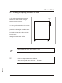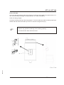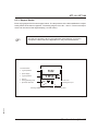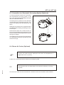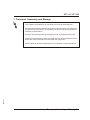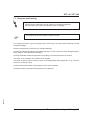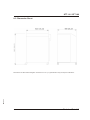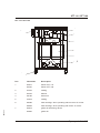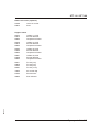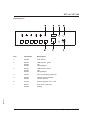
1
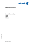
Operating Instructions
SM2-605
Dehumidified air dryer
STT 110
STT 160
Sterling Material Processing
STT 110 / STT 160
Sterling Material Processing
5200 West Clinton Ave.
Milwaukee, WI 53223
Telephone: (414) 354-0970
Fax: (414) 354-6421
www.sterlco.com
Technical service:
Service department
Telephone: (800) 423-3183
Edition: 04/02
These operating instructions are for*:
(* Please fill in personally)
Serial number:
Year of manufacture:
Date of delivery:
Number of delivery:
Date of commissioning:
SM2-605
Location:
Group of machines:
2
STT 110 / STT 160
Sterling Material Processing retains all rights to change the information in these
operating instructions at any time without notice.
SM2-605
We assume no liability for any errors or direct or indirect damage resulting in context with these operating instructions.
Copying, translation or publication in any form except for personal use of purchaser requires approval from Sterling Material Processing.
All rights reserved.
3
STT 110 / STT 160
Table of contents
1. General Information . . . . . . . . . . . . . . . . . . . . . . . . . . . . . . . . . . . . . . . . . . . . . . . . . . . . . . . 1-1
1.1.
1.2.
1.3.
1.4.
1.5.
Warnings and symbols . . . . . . . . . . . . . . . . . . . . . . . . . . . . . . . . . . . . . . . . . . . . . 1-2
Explanations and information . . . . . . . . . . . . . . . . . . . . . . . . . . . . . . . . . . . . . . . 1-4
Legal basis . . . . . . . . . . . . . . . . . . . . . . . . . . . . . . . . . . . . . . . . . . . . . . . . . . . . . . 1-4
Fields of applications . . . . . . . . . . . . . . . . . . . . . . . . . . . . . . . . . . . . . . . . . . . . . . 1-4
Notes on Usage . . . . . . . . . . . . . . . . . . . . . . . . . . . . . . . . . . . . . . . . . . . . . . . . . . 1-4
2. Safety instructions . . . . . . . . . . . . . . . . . . . . . . . . . . . . . . . . . . . . . . . . . . . . . . . . . . . . . . . . 2-1
2.1. For your safety . . . . . . . . . . . . . . . . . . . . . . . . . . . . . . . . . . . . . . . . . . . . . . . . . . . 2-2
2.2. For the safety of the devices . . . . . . . . . . . . . . . . . . . . . . . . . . . . . . . . . . . . . . . . 2-5
3. Start up . . . . . . . . . . . . . . . . . . . . . . . . . . . . . . . . . . . . . . . . . . . . . . . . . . . . . . . . . . . . . . . . . . 3-1
3.1. Initial Operation . . . . . . . . . . . . . . . . . . . . . . . . . . . . . . . . . . . . . . . . . . . . . . . . . . 3-2
3.1.1. Switching on the Dryer . . . . . . . . . . . . . . . . . . . . . . . . . . . . . . . . . . . . . . 3-2
3.2. Continuous Operation . . . . . . . . . . . . . . . . . . . . . . . . . . . . . . . . . . . . . . . . . . . . . 3-4
3.2.1. Switching the Dryer on . . . . . . . . . . . . . . . . . . . . . . . . . . . . . . . . . . . . . . 3-4
3.2.2. Setting the Drying Temperature . . . . . . . . . . . . . . . . . . . . . . . . . . . . . . . 3-5
3.3. Switching the Dryer off . . . . . . . . . . . . . . . . . . . . . . . . . . . . . . . . . . . . . . . . . . . . . 3-7
4. Error and error correction . . . . . . . . . . . . . . . . . . . . . . . . . . . . . . . . . . . . . . . . . . . . . . . . . . 4-1
SM2-605
5. Maintenance . . . . . . . . . . . . . . . . . . . . . . . . . . . . . . . . . . . . . . . . . . . . . . . . . . . . . . . . . . . . . . 5-1
5.1. Maintenance schedule . . . . . . . . . . . . . . . . . . . . . . . . . . . . . . . . . . . . . . . . . . . . . 5-3
5.2. Cleaning or Replacing the Air Filter . . . . . . . . . . . . . . . . . . . . . . . . . . . . . . . . . . 5-4
5.2.1. Cleaning or Replacing the Return Air Filter . . . . . . . . . . . . . . . . . . . . . 5-5
5.3. Disposing of Drying Agents . . . . . . . . . . . . . . . . . . . . . . . . . . . . . . . . . . . . . . . . . 5-6
5.3.1. . . . . . . . . . . . . . . . . . . . . . . . . . . . . . . . . . . . . . . . . . . . . . . . . . . . . . . . . . 5-6
5.3.2. . . . . . . . . . . . . . . . . . . . . . . . . . . . . . . . . . . . . . . . . . . . . . . . . . . . . . . . . . 5-6
5.3.3. . . . . . . . . . . . . . . . . . . . . . . . . . . . . . . . . . . . . . . . . . . . . . . . . . . . . . . . . . 5-6
5.3.4. . . . . . . . . . . . . . . . . . . . . . . . . . . . . . . . . . . . . . . . . . . . . . . . . . . . . . . . . . 5-6
5.3.5. . . . . . . . . . . . . . . . . . . . . . . . . . . . . . . . . . . . . . . . . . . . . . . . . . . . . . . . . . 5-6
5.3.6. . . . . . . . . . . . . . . . . . . . . . . . . . . . . . . . . . . . . . . . . . . . . . . . . . . . . . . . . . 5-6
5.3.7. . . . . . . . . . . . . . . . . . . . . . . . . . . . . . . . . . . . . . . . . . . . . . . . . . . . . . . . . . 5-6
5.3.8. . . . . . . . . . . . . . . . . . . . . . . . . . . . . . . . . . . . . . . . . . . . . . . . . . . . . . . . . . 5-6
5.3.9. . . . . . . . . . . . . . . . . . . . . . . . . . . . . . . . . . . . . . . . . . . . . . . . . . . . . . . . . . 5-6
5.4. Cleaning the Drying Hopper . . . . . . . . . . . . . . . . . . . . . . . . . . . . . . . . . . . . . . . . 5-7
6. Functional description . . . . . . . . . . . . . . . . . . . . . . . . . . . . . . . . . . . . . . . . . . . . . . . . . . . . . 6-1
4
STT 110 / STT 160
6.1. General Information . . . . . . . . . . . . . . . . . . . . . . . . . . . . . . . . . . . . . . . . . . . . . . . 6-2
6.2. Drying Hopper (Optional) . . . . . . . . . . . . . . . . . . . . . . . . . . . . . . . . . . . . . . . . . . . 6-5
6.2.1. Hopper Heater . . . . . . . . . . . . . . . . . . . . . . . . . . . . . . . . . . . . . . . . . . . . . 6-6
6.3. Connection to a Pneumatic Conveying System (Optional) . . . . . . . . . . . . . . . . 6-7
6.4. Return Air Cooler (Optional) . . . . . . . . . . . . . . . . . . . . . . . . . . . . . . . . . . . . . . . . 6-7
7. Transport, Assembly and Storage . . . . . . . . . . . . . . . . . . . . . . . . . . . . . . . . . . . . . . . . . . . 7-1
7.1. Tansport and Packing . . . . . . . . . . . . . . . . . . . . . . . . . . . . . . . . . . . . . . . . . . . . . 7-2
7.2. Assembly . . . . . . . . . . . . . . . . . . . . . . . . . . . . . . . . . . . . . . . . . . . . . . . . . . . . . . . . 7-3
7.3. Storage . . . . . . . . . . . . . . . . . . . . . . . . . . . . . . . . . . . . . . . . . . . . . . . . . . . . . . . . . 7-3
8. Assembly instructions . . . . . . . . . . . . . . . . . . . . . . . . . . . . . . . . . . . . . . . . . . . . . . . . . . . . . 8-1
8.1.
8.2.
8.3.
8.4.
Installation of the exhauster fan for regeneration of exhaust air. . . . . . . . . . . . 8-2
Grounding the equipment against electrostatic charging . . . . . . . . . . . . . . . . . 8-2
Electrical Connection . . . . . . . . . . . . . . . . . . . . . . . . . . . . . . . . . . . . . . . . . . . . . . 8-3
Connection of Return Air Cooler (Optional) . . . . . . . . . . . . . . . . . . . . . . . . . . . . 8-4
9. Technical Data . . . . . . . . . . . . . . . . . . . . . . . . . . . . . . . . . . . . . . . . . . . . . . . . . . . . . . . . . . . . 9-1
9.1. STT 110. . . . . . . . . . . . . . . . . . . . . . . . . . . . . . . . . . . . . . . . . . . . . . . . . . . . . . . . . 9-1
9.2. STT 160. . . . . . . . . . . . . . . . . . . . . . . . . . . . . . . . . . . . . . . . . . . . . . . . . . . . . . . . . 9-2
9.3. Dimension Sheet . . . . . . . . . . . . . . . . . . . . . . . . . . . . . . . . . . . . . . . . . . . . . . . . . 9-3
10. Spare parts list . . . . . . . . . . . . . . . . . . . . . . . . . . . . . . . . . . . . . . . . . . . . . . . . . . . . . . . . . 10-1
11. Electrical manual. . . . . . . . . . . . . . . . . . . . . . . . . . . . . . . . . . . . . . . . . . . . . . . . . . . . . . . . 11-1
o Connection diagram no.: _ _ _ _ _ _ _ _ _ _ _ _ _ _ _ _ _ _ _ _ _ _ _
o Currently not available; will be delivered at a later date !
12. Accessories . . . . . . . . . . . . . . . . . . . . . . . . . . . . . . . . . . . . . . . . . . . . . . . . . . . . . . . . . . . . 12-1
o Basic setting thermo regulator
o Digital timer
o ___________________________
o ___________________________
SM2-605
o ___________________________
5
STT 110 / STT 160
1. General Information
These operating instructions must be used by every person charged with
work on the unit.
SM2-605
»
These operating instructions are addressed to all users of the device.
General Information 1-1
STT 110 / STT 160
1.1. Warnings and symbols
The following warnings and symbols are used in these operating instructions:
L
This symbol indicates that serious injury is possible if the corresponding
instructions, regulations or warnings are not observed.
F
This symbol indicates that extensive damage to equipment is possible if
the corresponding instructions, regulations or warnings are not observed.
&
This symbol indicates information important for becoming familiar with
the equipment, i.e. technical correlations.
$
This symbol indicates that a technical term is explained at this point.
SM2-605
»
This symbol indicates danger to life! Fatal or serious injury is possible if the
corresponding instructions, regulations or warnings are not observed.
General Information 1-2
STT 110 / STT 160
When disposing of drying agents / batteries / oil, observe all official rules.
Caution: High noise pollution !
For all work on the equipment, hearing protection should be worn.
Avoids impairment of hearing!
Caution: Danger of crushing !
Disconnect the equipment from mains supply before starting
mainenance procedures. All compressed air pipes on the equipment
should be depressurised before starting maintenance work.
Caution: Danger of hot surface !
Before starting any work wait until all parts have been cooled down sufficiently. Avoid touching any of these parts!
Caution: Danger of skidding !
Remove any granules remaining on the ground.
SM2-605
Caution: Danger to life through electrical shock !
Observe that the control system is still under voltage even when the main
switch is switched off.
General Information 1-3
CTT 110 / CTT 160
1.2. Explanations and information
Various terms and designations are used in these operating instructions to ensure clarity. Therefore please note that the terms used in the text stand for the corresponding explanations listed below.
•
Equipment
”Equipment” can mean an individual unit, a machine or an installation.
•
Operating personnel
The ”operating personnel” are persons operating the equipment on their own responsibility or according to instructions.
•
Operator
The ”operator” of the equipment (production manager, foreman, etc.) is the person responsible for
all production sequences. The operator instructs the operating personnel of what is to be done.
•
Operating instructions
The ”operating instructions” describe the interaction of the equipment, production sequences or
methods. The operating instructions must be compiled by the operator of the equipment.
•
Equipment foreman
When several operating personnel work on one machine, the ”equipment foreman” coordinates
the sequences. The equipment foreman must be appointed by the operator.
•
Trained personnel
”Trained personnel” are persons who, due to their training, are authorized to carry out the required
work.
1.3. Legal basis
See “Manufacturer’s Certificate” resp. “Certificate of Conformity”.
1.4. Fields of applications
For the drying of thermoplastic granules and regrind before processing in order to remove all remaining moisture from the granules both inside and out, independent of climate or ambient air
conditions.
SM2-605
1.5. Notes on Usage
•
Experienced operators can begin directly with the chapter on “Start-up” if the unit has been properly installed.
•
If the unit has not been installed yet, observe the instructions in the chapter on “Assembly Instructions” and “Transport, Assembly and Storage”.
General Information 1-4
STT 110 / STT 160
2. Safety instructions
»
These safety instructions apply to all persons within the range of action of the
equipment.
Please inform all persons within the range of action of the equipment of the
direct and indirect hazards connected with the equipment.
These operating instructions are to be used by all persons assigned activities connected with the equipment.
Knowledge of the English language is prerequisite.
SM2-605
Ensure in each case that the operating personnel are familiar with the operating instructions and the function of the equipment.
Safety instructions 2-1
STT 110 / STT 160
2.1. For your safety
General
The operating personnel of this equipment must be at least 16 years old.
Please read these operating instructions carefully before taking into operation for the first time.
Contact us should questions arise. This avoids injury and damage to equipment!
These operating instructions must be kept available at all times at the place of operation of the
equipment. Improper operation results in danger of accidents!
Please note that, for reasons of clarity, not all conceivable cases regarding operation or maintenance of the equipment can be covered in these operating instructions.
Please observe all safety instructions and warnings on the equipment. This avoids injury and damage to equipment!
All work on the equipment is to be carried out by persons whose qualifications are specified in the
pertaining chapters of the operating instructions. Improper operation results in danger of accidents!
The proper working clothes are to be worn during any work on the equipment. This avoids injury!
The local regulations and requirements pertaining to this equipment must be observed.
Disconnect electrical components from the mains supply before work is car ried out on these components Caution: Danger to life through electrical shock!
Compile detailed operating instructions based on these Operating instructions for the sequence
of procedures to be carried out on this equipment. Improper operation results in danger of accidents!
SM2-605
Observe that the control system is still under voltage even when the main switch is switched off.
Caution: Danger to life through electrical shock!
Safety instructions 2-2
STT 110 / STT 160
Assembly
Compare the connected loads with those of the mains supply. Danger of injury through electrical
shock!
When using lifting gear, please observe the pertaining regulations. Caution: Danger of accidents!
Do not modify, add other equipment or change the design of the equipment without the approval
of the manufacturer. Caution: Danger of accidents!
Attachments not supplied by Sterling must be manufactured in accordance with safety regulation
EN 294. Danger of accidents!
The equipment may only be operated when all the associated components are properly connected up and in accordance with the relevant regulations. This avoids injury and damage to equipment!
Operate the device only if all its components are grounded. Danger: accident through electrical
shock!
Please note for installation that the equipment is top-heavy. Danger exists that it may topple over!
Take care that the device is not standing on the mains cable. This will prevent danger to people
and material!
Operation
Appoint an equipment foreman to be responsible for the equipment.
Ensure that the operating personnel are provided detailed instruction in the operation of the
equipment. Improper operation results in danger of accidents!
When the main switch is switched off for reasons pertaining to safety, it must be secured against
unauthorized activation. Caution: Danger of accidents!
Repair work may be carried out by trained personnel only. Caution: Danger of accidents!
Never operate the equipment when partially dismantled! Danger! Limbs may be caught in machinery! Electric shock!
In case of malfunction, shut down the equipment immediately. Have malfunctions corrected immediately. Danger of accidents!
The machine is intended only for the drying of granulated plastics. Any other or additional use is
contrary to specifications.
This equipment is not suitable for food processing.
The safety instructions of the connected machines must be followed.
Please note that sound levels exceeding 85 db(A) may in the long term damage your health. Use
the appropriate ear muffs. This avoids impairment of hearing!
SM2-605
Please note that the drying cells, drying hoppers and air pipings grow hot during use. Avoid touching any of these parts! Danger: Injury through burns!
Never operate the dryer without side panels. Danger: Limbs may be caught in machinery! Injury
through burns!
Safety instructions 2-3
STT 110 / STT 160
Operate the dryer only if there is at least one drying hopper operating. This will prevent damage of
material!
When drying plastics which emit gases dangerous for human health, take care that the regeneration exhaust air is disposed of without polluting the environment. This will prevent danger to people and material!
Maintenance
Before starting maintenance work, appoint a supervisor.
Inform the responsible personnel before maintenance work on the system is started. Caution:
Danger of accidents!
Disconnect the equipment from mains supply before starting maintenance procedures to ensure
that it cannot be switched on unintentionally. Caution: Danger of accidents!
All pipes, hoses and scre wed connections should be checked regularly for leaks and damage.
Any faults which arise should be corrected immediately. Danger of accidents!
Depressurize all compressed air piping before starting maintenance work. Danger of accidents!
The air filters should only be cleaned/replaced when the the main switch is off and the blower has
stopped. This avoids injury and damage to equipment!
Any maintenance work on the equipment should only be started when the the main switch is off
and the blower has stopped. This avoids injury and damage to equipment!
Check the v-belts of the blower only when the main switch is switched off and the blowers have
stopped. Caution: Danger of accidents!
Open drying hoppers only if they are completely empty. Danger of accidents!
Never open drying hoppers while the device is in operation. Danger: Injury through burns!
Open drying hoppers only if they have been cooled down sufficiently. Danger: Injury through
burns!
Before starting maintenance work wait until the drying cells, drying hoppers and air pipings have
been cooled down sufficiently. Avoid touching any of these parts! Danger: Injury through burns!
Remove any granules remaining on the ground. Danger of accidents!
SM2-605
Arrest the wheels after installation if the dryer is mounted on a movable frame. This will prevent
danger to people and material!
Safety instructions 2-4
STT 110 / STT 160
2.2. For the safety of the devices
Never change settings without carefully assessing the consequences.
Use only original Sterling spare parts.
Observe the maintenance instructions.
Keep a record of all maintenance works and repairs.
Please note that electronic components can be damaged by static discharge.
Before initial operation and in regular intervals, make sure that no electrical connections are loose.
Never readjust sensors without exactly knowing their functions.
Please ensure that the permitted storage temperature lies between 0 and +55 °C
(32 to +131 °F).
Please ensure that the permitted operation temperature lies between 0 and +45 °C
(32 to +113 °F).
Check the direction of rotation of the blowers after the electrical connections have been made
(see rotational direction arrow).
Clean the drying hoppers before the first filling.
Note the instructions of the material manufacturer for the maximum drying temperature.
Note the drying instructions of the material manufacturer.
Take care that the drying hoppers are always completely filled and that the retention period is respected if continual removal is taking place.
Note that too large amounts taken from the drying hopper lead to insufficient drying of the material.
Close the air stop valves of drying hoppers which are empty or have not been used.
Note down all data which you have entered into the control system.
The password is to be entrusted to authorised personnel only.
Please note that the temperature of the dryer heating system must always be set lower than that of
the supplementary heaters.
When you dispose of drying agents, observe all official rules.
Note that drying cells are replaced or refilled by Sterling only if they are empty.
The material level may not fall below 40 % in the drying hopper, when material is continuously removed from the drying hopper, but no material is continuously fed into the drying hopper (batch
drying). Close the throttle valves.
SM2-605
Read the operating manuals of the connected devices.
Safety instructions 2-5
STT 110 / STT 160
3. Start up
»
This chapter is addressed to the operators of the machine.
This chapter assumes general skills with drying equipment.
This chapter assumes that the functional description has been read and understood.
It must be ensured that the operators have the required experience.
F
Make sure that the main switch is at “0" position.
Check the drying hopper for cleanliness.
Check to see whether the adhesive film on the drying hopper has be removed.
If there is a return air cooler, switch on its coolant circuit.
If there is a timer clock (optional), adjust it. Read the operating manual of
the timer clock.
Check whether the release switch “Timer” and the release switches
“Hopper” (ST1 - ST6) are at ”0" position.
The signal lamp “trouble” may flash shortly while the valve block is changed.
SM2-605
&
Start up 3-1
STT 110 / STT 160
3.1. Initial Operation
Check whether the inlet of the drying hopper is closed by a blind lid, or whether a conveyor unit
(optional) is installed.
If not, manufacture a suitable blind lid and install it on the inlet of the drying hopper or install the
conveyor unit (optional).
F
Attachments which are not supplied by Sterling must be manufactured
according to the safety regulation European Standard 294.
Check whether the coolant circuit of the return air cooler is turned on (if a return air cooler is installed).
3.1.1. Switching on the Dryer
Switch on the main switch of the dryer.
&
The signal lamp “power” goes on.
For operation with timer clock (optional):
Turn the release switch “Timer” at position:
SM2-605
For operation without timer clock:
Turn the release switch “Timer” at position:
&
The blower is running.
F
If the dryer has not been in use for several months it must be operated for
about 2 hours without material.
Start up 3-2
STT 110 / STT 160
Turn the release switches “Hopper” (ST1 - ST6) at “I” position.
Turn the thermo regulator to +80 °C (176°F) for the drying temperature.
Press the “PGM” key.
Set by means of the arrow keys the drying temperature to “80".
After 2 seconds the display flashes and the value is stored.
Press the “EXIT” key (the setpoint value and the actual value
of the drying temperature are displayed).
EXIT
After 2 hours turn the release switches “Hopper” (ST1 - ST6) at “0” position.
Turn the release switch “Timer” at position:
L
Wait until the blower has stopped.
The run on time of the blower is 10 minutes.
If there is a return air cooler installed, switch off its coolant circuit.
Switch off the main switch of the dryer.
The signal lamp “power” goes off.
SM2-605
&
Start up 3-3
STT 110 / STT 160
3.2. Continuous Operation
F
Fill at least half of the drying hopper with material.
3.2.1. Switching the Dryer on
Switch on the main switch of the dryer.
&
The signal lamp “power” goes on.
For operation with timer clock (optional):
Turn the release switch “Timer” at position:
For operation without timer clock:
Turn the release switch “Timer” at position:
The blower is running.
SM2-605
&
Start up 3-4
STT 110 / STT 160
3.2.2. Setting the Drying Temperature
Turn the release switches “Hopper” (ST1, ST2) at “I” position.
For each drying hopper, set the required drying temperature (= desired value) by means of the respective thermo regulator.
Check whether the set drying temperature is appropriate for the materials which have been filled
in.
Observe the instructions of the material manufacturer.
After the first filling, process the material only after the retention period is over.
Observe the instructions of the material manufacturer.
Press the “PGM” key.
By means of the arrow keys select the desired value for
the drying temperature.
After 2 seconds the display flashes and the value is stored.
Press the “EXIT” key (the setpoint value and the actual value
of the drying temperature are displayed).
After a change of materials, immediately check and correct the set drying
temperature.
SM2-605
F
EXIT
Start up 3-5
STT 110 / STT 160
Optimizing the thermo regulator
Press the “EXIT” key for at least 2 seconds.
“tunE” flashes. The optimization can take several minutes.
EXIT
60
tunE
PGM
If “tunE” stops flashing, the optimization is finished.
K1 K2
K3
EXIT
60
tunE
PGM
EXIT
Press the “EXIT” key.
SM2-605
EXIT
Start up 3-6
STT 110 / STT 160
3.3. Switching the Dryer off
Set the release switch “Timer” at position:
L
Wait until the blower has stopped.
The run on time of the blower is 10 minutes.
If there is a return air cooler installed, switch off its coolant circuit.
Switch off the main switch of the dryer.
The signal lamp “power” goes off.
SM2-605
&
Start up 3-7
STT 110 / STT 160
4. Error and error correction
»
This chapter is directed at the operators of the equipment.
This chapter assumes general skills in dealing with drying systems.
This chapter assumes that the “start-up” description has been read and understood.
It should be ensured in each and every case that the operators have the relevant skills.
F
Faults must be eliminated before the control system can again start operating.
&
An alarm is indicated by steady light of the signal lamp “trouble”.
SM2-605
When the fault has been eliminated, the signal lamp “trouble” goes off.
Error and error correction 4-1
STT 110 / STT 160
The follow ing errors can lead to an alarm:
Blower
The pressure of the blower is too low.
Check the blower.
Vacuum sensor defective.
Regeneration heater 1
The safety temperature limiter of the regeneration heater 1 has been activated.
Check the safety temperature limiter.
Sterling Service.
Regeneration heater 2
The safety temperature limiter of the regeneration heater 2 has been activated.
Check the safety temperature limiter.
Sterling Service.
SM2-605
Hopper heater
The safety temperature limiter of the hopper heater has been activated.
Check the safety temperature limiter.
Sterling Service.
Error and error correction 4-2
STT 110 / STT 160
5. Maintenance
»
This chapter is intended for persons with skills in electrical and mechanical
areas due to their training, experience and received instructions.
Personnel using the instructions in this chapter must be instructed of the regulations for the prevention of accidents, the operating conditions and safety
regulations and their implementation.
Ensure in each case that the personnel are informed.
For maintenance work taking place at theights of over approx. 1829 mm (6
ft.), use only ladders or similar equipment and working platforms intended for
this purpose. At greater heights, the proper equipment for protection against
falling must be worn.
Use only suitable lifting gear which is in proper work ing order and load suspension devices with sufficient carrying capacity. Do not stand or work under
suspended loads!
Ensure that the electric motors/switch cabinets are sufficiently protected
against moisture.
Use suitable workshop equipment.
Before starting maintenance work, appoint a supervisor.
Inform the responsible personnel before maintenance work on the system is
started.
Never operate the equipment when partially dismantled.
Any maintenance and repair work NOT described here may only be carried
out by Sterling service personnel or by specialised staff authorised by
Colortronic.
L
Disconnect the equipment from mains supply before starting
mainenance procedures to ensure that it cannot be switched on unintentionally.
SM2-605
All compressed air pipes on the equipment should be depressurised before starting maintenance work.
Maintenance 5-1
STT 110 / STT 160
F
Please observe the maintenance schedule.
Before starting maintenance work, clean the equipment of oil, fuel or lubricant.
Ensure that materials and incidentals required for operation as well as
spare parts are disposed of properly and in an environmentally sound
manner.
Use only original Sterling spare parts.
SM2-605
Keep record of all maintenance and repair procedures.
Maintenance 5-2
STT 110 / STT 160
5.1. Maintenance schedule
Daily:
Check warning signs on equipment for good
legibility and completeness
Clean return air filters and casing (depending
on dust build-up)
Weekly:
Check main switch for proper function
Check the signal lamps for proper functioning
Every six months:
Change return air filters (depending on dust build-up)
Clean air filter of the suction box
All electrical and mechanical connections
should be checked to see if they fit securely
Annually:
Dewpoint should be checked (only by
Sterling service personnel)
Whenever the
material is changed:
The drying hopper and suction box must be cleaned
&
The service intervals refer to a 3-shift operation.
F
The given maintenance intervals are average values.
SM2-605
Check whether in your individual case the maintenance intervals must be
shortened.
Maintenance 5-3
STT 110 / STT 160
5.2. Cleaning or Replacing the Air Filter
Set the release switch “Timer” at position:
L
Wait until the blower has stopped.
The run on time of the blower is 10 minutes.
If there is a return air cooler installed, switch off its coolant circuit.
L
Switch off the main switch of the dryer (the signal lamp “power” goes off).
Interrupt the mains supply so that the device cannot be switched on unintentionally.
Clogged filters substantially reduce the amount of circulating air and lead
to a production lag of your dryer. Clogged filters may also damage the
heating elements.
SM2-605
&
Maintenance 5-4
STT 110 / STT 160
5.2.1. Cleaning or Replacing the Return Air Filter
STT 110 / STT 160
Detach the nut on the housing of the return
air filter and remove the housing cover.
Air filter
Remove the nut of the filter cartridge.
Remove the filter cartridge.
Clean the inside of the return air filter housing. Use non-fibrous cleaning cloths or an
industrial type vacuum cleaner.
Blow compressed air from the inside out
through the clogged filter cartridge or replace the filter cartridge.
Re-install the cleaned/new filter cartridge.
Mount the nut.
Install the lid of the return air filter
housing.
Fix the nut.
STT 110 / STT 160
&
Purchase order numbers return air filter
when operating without return air cooler: ID 88366
when operating with return air cooler:
ID 88628
SM2-605
F
Never operate the dryer without return air filter.
Maintenance 5-5
STT 110 / STT 160
5.3. Disposing of Drying Agents
Please note that drying cells are replaced or refilled by Sterling only if they are empty.
When disposing of drying agents, observe all official rules.
Since used drying agents may contain impurities from the dried materials, treat them as special waste.
&
It is not possible for Sterling to take back the used drying agent or drying
cells with used drying agents.
5.3.1.
5.3.2.
5.3.3.
5.3.4.
5.3.5.
5.3.6.
5.3.7.
SM2-605
5.3.8.
5.3.9.
Maintenance 5-6
STT 110 / STT 160
5.4. Cleaning the Drying Hopper
Set the release switch “Timer” at position:
L
Wait until the blower has stopped.
The run on time of the blower is 10 minutes.
If there is a return air cooler installed, switch off its coolant circuit.
L
Switch off the main switch of the dryer (the signal lamp “power” goes off).
Interrupt the mains supply so that the device cannot be switched on unintentionally.
F
Clean the drying hopper each time you are changing the materials.
Make sure that the drying hopper has cooled down sufficiently.
Make sure that the drying hopper is completely empty.
SM2-605
Remove any granules remaining on the ground.
Maintenance 5-7
STT 110 / STT 160
ST 25
Open the toggle-type fasteners (A) at the hopper lid
and fold the hopper lid upwards (if in use: remove before the single conveyor).
A
Clean the drying hopper.
Close the hopper lid and close the toggle-type fasteners (A) (if in use: re-mount the single conveyor).
TT 25
SM2-605
F
Remove any granules remaining in the cleaning opening.
Maintenance 5-8
STT 110 / STT 160
ST 60 - ST 1600
Open the cleaning opening of the drying hopper: Lift and turn the handle (A) to open the lock, if in
use: remove before the single conveyor (ST 400 - ST 1600: 2 handles).
Clean the drying hopper.
Close the cleaning opening of the drying hopper: Turn the handle (A) until the cleaning opening is
locked and then close the handle (if in use: re-mount the single conveyor).
ST 1200 and ST 1600: Clean the bead.
SM2-605
F
Remove any granules remaining in the cleaning opening.
Maintenance 5-9
STT 110 / STT 160
6. Functional description
»
This functional description is addressed to the operators of the equipment.
This functional description assumes general familiarity with drying equipment.
SM2-605
It should be verified that the operators do indeed have the appropriate skills.
Functional description 6-1
STT 110 / STT 160
6.1. General Information
The dehumidified air dryers were developed for drying plastic granules. Due to their compact construction, they can be employed next to the processing machine (drying hopper on the processing
machine) or with one or more drying hoppers as a movable facility (compact facility).
The dryers work ac cording to the dehumidified air principle, i.e., the air is not only heated but also
dehumidified before it flows through the drying hopper.
In this manner, plastic granules can be dried down to a very small residual moisture content.
The drying temperature can be adjusted, if necessary, up to a maximum of +180 °C (356°F) (upper limit). Due to the heat that is released during water absorption in the drying cells, the lower
limit of the dehumidified air temperature is approx. +60 °C (140°F).
The drying takes place continuously, i.e., there are no rest periods due to regeneration of the drying agent.
The dryer may only be put into operation if the drying hopper is filled.
SM2-605
F
The dryer is rated for continuous operation.
Functional description 6-2
STT 110 / STT 160
All function sequences are fully automatic.
The dryer is equipped with two drying cells. One drying cell is part of the drying cycle; the other
drying cell is regenerated simultaneously.
Part of the dehumidified air is used for regenerating the moist drying cell. At the beginning of regeneration, it is heated by the regeneration heater. After the end of the heating period, the drying cell
is cooled off by means of dehumidified air. After the switch-over time is reached, the regenerated
drying cell is included in the drying cycle, and the cycle starts again.
SM2-605
1
2
3
4
5
6
7
8
9
Drying cell
Regenerating heater
Drying hopper
Diaphragm
Return air filter
Blower
Valve
Drying heater
Suction box
Functional diagram
Functional description 6-3
STT 110 / STT 160
A digital display of the current dew point temperature can be supplied as additional equipment.
As an option, a timer clock can be supplied which switches the dryer on or off at preselected times.
Read the operating manual of the timer clock.
F
1
2
8
1
2
3
4
5
6
7
8
=
=
=
=
=
=
=
=
7
3
4
6
5
release switch “hopper” ST1-ST6
dew point display (optional)
signal lamp “power”
signal lamp “trouble”
main switch
release switch “Timer”
timer clock (optional)
thermo regulator “drying hopper” ST1-ST6
SM2-605
Operating unit
Functional description 6-4
STT 110 / STT 160
6.2. Drying Hopper (Optional)
The material is dried in the drying hopper.
The dehumidified air is conducted through
the material in the drying hopper and takes
up moisture. Drying hoppers must have the
appropriate dimensions for their specific use
so that the desired final moisture content is
reached. When refilling a drying hopper, the
material must first be dried completely before
material can be taken out for the first time.
If material is taken out continuously, there
must also be a continual addition of material
into the drying hopper (continuous drying
process). New (moist) material is conducted
into the upper opening of the drying hopper
and slowly reaches the material outlet at the
lower end. On its way from the upper to the
lower end, the material is dried down to the final moisture content.
In order to guarantee a continuous drying
process, we recommend that you always
keep the drying hopper filled completely.
SM2-605
Drying Hopper
Functional description 6-5
STT 110 / STT 160
6.2.1. Hopper Heater
Each drying hopper has its own hopper heater. The temperature of the dehumidified air is adjusted by means of the thermo regulator. The setting range is from +60 - +180 °C. The current temperature can be read off the digital display (= actual value).
F
The thermo regulator is factory-programmed. Nevertheless, you have to
set specific values which are dependent on the processed material.
Process display
drying temperature
Setpoint display
drying temperature
“PGM” key,
Selecting operating level
or parameter selecti on
60
180
PGM
reducing setpoint value
K1 K2
K3
EXIT
“EXIT” key,
Aborting the input
increasing setpoint value
SM2-605
Thermo regulator
Functional description 6-6
STT 110 / STT 160
6.3. Connection to a Pneumatic Conveying System (Optional)
Your drying facility works best in combination
with a pneumatic conveying system. In this
way, your drying hopper will always be supplied with sufficient material.
The facility will only take as much material as
is required by the processing machines. Therefore, the drying result will always be the
same.
Sterling drying hoppers are equipped with a
suitable flange for adding a Sterling pneumatic conveyor.
Suction boxes with one or three suction tubes can be supplied as well (optional). These
suction boxes are developped specifically for
this type of hopper.
A
The loading of the conveying line with material is adjusted by closing or by opening of the
control cover (A).
Suction box
6.4. Return Air Cooler (Optional)
F
A return air cooler must be employed if the return air temperature is
higher than +65 °C (149°F).
A return air cooler improves the efficiency of the drying cells.
SM2-605
&
The lower the return air temperature, the better the efficiency of the drying cells.
The return air cooler can be connected to a coolant circuit or to the water mains network.
Functional description 6-7
STT 110 / STT 160
7. Transport, Assembly and Storage
»
This chapter is intended for all operating personnel of the equipment.
Personnel using these instructions must be instructed in the regulations for
the prevention of accidents, the operating conditions and safety regulations
and their implementation.
Ensure in each case that the operating personnel are sufficiently informed.
Please inform all persons within the range of action of the equipment of the
direct and indirect hazards connected with the equipment.
SM2-605
Please observe all safety regulations for the operation of lifting equipment.
Transport, Assembly and Storage 7-1
STT 110 / STT 160
7.1. Tansport and Packing
»
F
Please ensure adequate carrying capacity of the lifting equipment.
Note that the dryer system is top-heavy. Risc of toppling!
The machine must not be tilted or laid on its side.
The equipment pass a rigorous operating test in the factory and are packed carefully to avoid
transport damage.
Please check packing on delivery for transport damage.
The inlet and discharge flanges are sealed with plugs, so that no dirt can enter during transport.
Plugs must be removed before assembly.
Packing materials should be disposed of according to environmental laws or reused.
The dryer or the compact unit is delivered on a pallet.
The dryer should only be moved by means of the appropriate lifting equipment (e. g. a fork lift
truck or a workshop crane).
Fasten the transport cables to the eyelets of the control cabinets.
SM2-605
Transport must be shock-proofed and free from vibrations.
Transport, Assembly and Storage 7-2
STT 110 / STT 160
7.2. Assembly
»
Please ensure adequate carrying capacity of the lifting equipment.
Check the carrying capacity of the point of installation, particularly if installed
on a platform.
The place selected for installation should be as free of vibrations as possible.
The main switch must be freely accessible.
Ground the equipment against electrostatic charging.
F
The machine must not be tilted or laid on its side.
Because of its compact construction the dryer can be installed directly beside the processing machine (drying hopper on the processing machine) or with one or more drying hoppers as a movable facility (compact facility).
Special foundations are not necessary for installation.
The dryer must be installed on a level surface and must not be exposed to excessive humidity.
The maximum permissible ambient temperature is 45 °C (113°F).
To facilitate servicing, the dryer should be installed in such a way that that it is accessible from
3 sides. Make sure that the air filters can be changed without problems.
To conserve energy, keep the distance between dryer, hopper and processing machine as small
as possible.
The wheels of the compact unit should be locked to ensure stable installation.
The foil should be removed from the drying hopper.
7.3. Storage
The control system may only be stored at temperatures from 0 to +55°C (32 to +131 °F).
SM2-605
Between delivery and machine commissioning the equipment should be stored in a dry, dust-free
and vibration-free room.
Transport, Assembly and Storage 7-3
STT 110 / STT 160
8. Assembly instructions
»
These installation instructions are intended for persons with skills in electrical and mechanical areas due to their training, experience and received instructions.
Personnel using these installation instructions must be instructed in the regulations for the prevention of accidents, the operating conditions and safety
regulations and their implementation.
Ensure in each case that the personnel are informed.
The installation instructions provided in the corresponding operating instructions apply for all connected equipment.
Observe safety regulations with regard to lifting gear handling.
All installation work must be carried out with the equipment disconnected
from electrical power and compressed air supply.
L
For installation work taking place at heights of over approx. 6 feet (1829
mm), use only ladders or similar equipment and working platforms intended for this purpose. At greater heights, the proper equipment for protection against falling must be worn.
Use only suitable lifting gear which is in proper work ing order and load
suspension devices with sufficient carrying capacity. Do not stand or
work under suspended loads!
Use suitable workshop equipment.
SM2-605
F
Install the equipment such that all parts are easily accessible; this facilitates maintenance and repair work
Assembly instructions 8-1
STT 110 / STT 160
8.1. Installation of the exhauster fan for regeneration of exhaust air
When plastics are being dried that release harmful gases during the drying process, care must be
taken that the regeneration exhaust air is disposed of in an environmentally sound way. At the
same time the throughput of the regeneration blower must not be altered. It should be noted when
assembling a disposal system (e.g. an exhauster system) that the regeneration exhaust air is very
humid. Thus condensation may form, which must not under any circumstances return to the dryer.
8.2. Grounding the equipment against electrostatic charging
Considerable electrostatic charging may occur in the equipment during processing of the various
materials. For this reason, all components must be sufficiently grounded, see grounding bolt
dryer (A) and drying hopper (B).
Ensure that the regulations of the local electric supply company are observed.
A
B
SM2-605
Grounding the equipment
Assembly instructions 8-2
STT 110 / STT 160
8.3. Electrical Connection
»
The electrical connection of the dryer and of the hopper heaters may only be
carried through or assigned by Sterling service staff or by qualified staff authorized by Sterling.
Other persons are not permitted to carry through the electrical connection.
Observe the rules of the local electricity board.
The main switch must be freely accessible.
Ground the equipment against electrostatic charging.
F
Regularly make sure that none of the electrical or screw connections are
loose.
Make sure that the main switch is at “0" position before the electrical connection is carried out.
The operating voltage is 480/3/60
Special voltages can be supplied on request.
The connected loads* are
STT 110 . . . . . . . . . . . . . . . . . . . . . . . . . . . . . . . . . . . . . . . . . . . . . . . . . . . . . . . . approx. 3.2 kW;
STT 160 . . . . . . . . . . . . . . . . . . . . . . . . . . . . . . . . . . . . . . . . . . . . . . . . . . . . . . . . approx. 3.6 kW.
*If hopper heaters are installed, the value of each hopper heater must be added to these connected loads (max. 9.0 kW).
SM2-605
The fuse protection must have 32 A.
Assembly instructions 8-3
STT 110 / STT 160
8.4. Connection of Return Air Cooler (Optional)
F
A return air cooler must be employed if the return air temperature is
higher than +65 °C (149°F).
You can connect the return air cooler to a coolant circuit or to the water mains network.
The water flow rate in the water mains network* is for:
STT 110. . . . . . . . . . . . . . . . . . . . . . . . . . . . . . . . . . . . . . . . . . . . approx. 0.35 m3/h (12.46 cf/h)
STT 160 . . . . . . . . . . . . . . . . . . . . . . . . . . . . . . . . . . . . . . . . . . . . approx. 0.48 m3/h (17.05 cf/h)
(*water temperature: +6 °C) (42.8°F)
Rate your coolant circuit accordingly.
Connect the coolant in- and outlets to the return air cooler.
Observe the flowing direction of the coolant.
Check the tightness of the connections.
SM2-605
Connection of the return air cooler
STT 110 / STT 160
Assembly instructions 8-4
STT 110 / STT 160
9. Technical Data
9.1. STT 110
amount of dehumidified air:. . . . . . . . . . . . . . . . . . . . . . . . . . . . . max. 110 m3/h (3,8846.1 cf/h)
operating voltage:. . . . . . . . . . . . . . . . . . . . . . . . . . . . . . . . . . . . . . . . . . . . . . . 400 V/3 AC/50 Hz
special voltages can be supplied on request
connected load: . . . . . . . . . . . . . . . . . . . . . . . . . . . . . . . . . . . . . . . . . . . . . . . . . . . . . . . . . 3.2 kW
calorific output (drying)*: . . . . . . . . . . . . . . . . . . . . . . . . . . . . . . . . . . . . . . . . . . . . . . max. 9.0 kW
*depending on the equipment with hopper heaters
calorific output (regenerating):. . . . . . . . . . . . . . . . . . . . . . . . . . . . . . . . . . . . . . . . . . . . . . 2.4 kW
driving power (drying, regenerating): . . . . . . . . . . . . . . . . . . . . . . . . . . . . . . . . . . . . . . . 0.75 kW
drying temperature: . . . . . . . . . . . . . . . . . . . . . . . . . . . . . . . . . . . . . . . . . . max. +180 °C(356°F)
width: . . . . . . . . . . . . . . . . . . . . . . . . . . . . . . . . . . . . . . . . . . . . . . . . . . . . . . . . . 900 mm (35.5 in.)
depth:. . . . . . . . . . . . . . . . . . . . . . . . . . . . . . . . . . . . . . . . . . . . . . . . . . . . . . . . . 666 mm (26.2 in.)
height: . . . . . . . . . . . . . . . . . . . . . . . . . . . . . . . . . . . . . . . . . . . . . . . . . . . . . . . 1320 mm (52.0 in.)
weight: . . . . . . . . . . . . . . . . . . . . . . . . . . . . . . . . . . . . . . . . . . . . . . . approx. 180 kg (396.83 lbs.)
noise: . . . . . . . . . . . . . . . . . . . . . . . . . . . . . . . . . . . . . . . . . . . . . . . . . . . . . . . . . approx. 66 dB (A)
options: . . . . . . . . . . . . . . . . . . . . . . . . . . . . . . . . . . . . . . . . . . . . . . . . . . . . . . . . . . . . . timer clock
. . . . . . . . . . . . . . . . . . . . . . . . . . . . . . . . . . . . . . . . . . . . . . . . . . . . . . . . . . . . . . dew point display
. . . . . . . . . . . . . . . . . . . . . . . . . . . . . . . . . . . . . . . . . . . . . . . . . . . . . . . . . . . . . . . return air cooler
Return Air Cooler
water flow rate in the water mains network*:. . . . . . . . . . . . . . . approx. 0.35 m3/h (12.46cf/h)
(*water temperature: +6 °C) (42.8°F)
SM2-605
Ø pipe connection:. . . . . . . . . . . . . . . . . . . . . . . . . . . . . . . . . . . . . . . . . . . . . . . . . . . 1/2” (0.5 in.)
Technical Data 9-1
STT 110 / STT 160
9.2. STT 160
amount of dehumidified air:. . . . . . . . . . . . . . . . . . . . . . . . . . . . . max. 160 m3/h (5,650.35 cf/h)
operating voltage:. . . . . . . . . . . . . . . . . . . . . . . . . . . . . . . . . . . . . . . . . . . . . . . 400 V/3 AC/50 Hz
special voltages can be supplied on request
connected load: . . . . . . . . . . . . . . . . . . . . . . . . . . . . . . . . . . . . . . . . . . . . . . . . . . . . . . . . . 3.6 kW
calorific value (drying)*:. . . . . . . . . . . . . . . . . . . . . . . . . . . . . . . . . . . . . . . . . . . . . . . max. 9.0 kW
*
depending on the equipment with hopper heaters
calorific value (regenerating): . . . . . . . . . . . . . . . . . . . . . . . . . . . . . . . . . . . . . . . . . . max. 2.4 kW
driving power (drying, regenerating): . . . . . . . . . . . . . . . . . . . . . . . . . . . . . . . . . . . . . . . . 1.1 kW
drying temperature: . . . . . . . . . . . . . . . . . . . . . . . . . . . . . . . . . . . . . . . . . . max. +180 °C (356°F)
width: . . . . . . . . . . . . . . . . . . . . . . . . . . . . . . . . . . . . . . . . . . . . . . . . . . . . . . . . 900 mm (35.46 in.)
depth:. . . . . . . . . . . . . . . . . . . . . . . . . . . . . . . . . . . . . . . . . . . . . . . . . . . . . . . . . 666 mm (26.2 in.)
height: . . . . . . . . . . . . . . . . . . . . . . . . . . . . . . . . . . . . . . . . . . . . . . . . . . . . . . . 1320 mm (52.0 in.)
weight: . . . . . . . . . . . . . . . . . . . . . . . . . . . . . . . . . . . . . . . . . . . . . . approx. 195 kg (432.10 lbs.)s
noise: . . . . . . . . . . . . . . . . . . . . . . . . . . . . . . . . . . . . . . . . . . . . . . . . . . . . . . . . . approx. 72 dB (A)
options: . . . . . . . . . . . . . . . . . . . . . . . . . . . . . . . . . . . . . . . . . . . . . . . . . . . . . . . . . . . . . timer clock
. . . . . . . . . . . . . . . . . . . . . . . . . . . . . . . . . . . . . . . . . . . . . . . . . . . . . . . . . . . . . . dew point display
. . . . . . . . . . . . . . . . . . . . . . . . . . . . . . . . . . . . . . . . . . . . . . . . . . . . . . . . . . . . . . . return air cooler
Return Air Cooler
water flow rate in the water mains network*: . . . . . . . . . . . . . . . approx. 0.48 m3/h(17.05 cf/h)
(*water temperature: +6 °C) (42.8°F)
SM2-605
Ø pipe connection:. . . . . . . . . . . . . . . . . . . . . . . . . . . . . . . . . . . . . . . . . . . . . . . . . . . 1/2” (0.5 in.)
Technical Data 9-2
STT 110 / STT 160
9.3. Dimension Sheet
SM2-605
Dimensions and data without obligation. Dimensions in mm. (in.) Specifications may be subject to alterations.
Technical Data 9-3
STT 110 / STT 160
10. Spare parts list
Other persons are not permitted to modify or repair the equipment.
SM2-605
»
This spare parts list is intended to be used only by trained personnel.
Spare parts list 10-1
STT 110 / STT 160
STT 110 / STT 160
1
6
2
2
4
5
2, 3
7
Pos.
ID-number
Description
1
85677
blower STT 110
85367
blower STT 160
2
94233
sealing
3
85323
diffusor
4
96196
desiccant
5
23918
sealing
6
88366
filter cartridge, when operating without return air cooler
88628
filter cartridge, when operating with return air cooler
85819
guide roll with fixing device
85820
guide roll
SM2-605
7
Spare parts list 10-2
STT 110 / STT 160
Return air cooler (optional)
29786
return air cooler
83972
hose
Hopper heater
85343
84512
85652
radiator 1,5 kW
thermal breaker
temperature limiter
85338
84510
85652
radiator 3,0 kW
thermal breaker
temperature limiter
85363
84509
85652
radiator 6,0 kW
thermal breaker
temperature limiter
85651
84508
85652
radiator 9,0 kW
thermal breaker
temperature limiter
86371
89846
93303
86387
Pt
Pt
Pt
Pt
18232
air control flap
84492
thermometer
06925
flow indicator
(3 m)
(6 m)
(9 m)
(12 m)
SM2-605
100
100
100
100
Spare parts list 10-3
STT 110 / STT 160
Operating unit
5
4
6
7
ID-number
Description
1
82368
main switch
2
82394
82393
82495
LED element, green
cap
fixing adapter
3
82494
82392
82495
LED element, white
cap
fixing adapter
4
26207
dew point display (optional)
5
82395
82490
selector switch actuator
contact element
6
87454
thermo regulator TT1 - TT6
7
85241
83646
timer clock (optional)
sealing
2
1
SM2-605
Pos.
3
Spare parts list 10-4
STT 110 / STT 160
Control unit
motor
85675
radiator 2.4 kW
95819
pull-button
87440
contact element
83975
controller
85275
temperature limiter
88914
contactor
87933
power supply
83647
cut-out
88907
terminal
99815
fuse
84982
relay holder
84983
relay
83624
terminal
84512
thermal breaker STT 110
84511
thermal breaker STT 160
84159
auxiliary switch
SM2-605
86376
Spare parts list 10-5
STT 110 / STT 160
11. Electrical manual
»
This electrical manual is intended to be used only by Sterling service personnel and trained personnel authorized by Sterling.
Other persons are not permitted to modify or repair the equipment.
o Connection diagram no.: _ _ _ _ _ _ _ _ _ _ _ _ _ _ _ _ _ _ _ _ _ _ _
SM2-605
o Currently not available; will be delivered at a later date !
Electrical manual 11-1
STT 110 / STT 160
12. Accessories
o Basic setting thermo regulator
o Digital timer
o Spare parts list Drying Hoppers ST 25 - ST 6400
o ___________________________
SM2-605
o ___________________________
Accessories 12-1
STT 110 / STT 160
Basic setting thermo regulator
»
This information is intended to be used only by Sterling service personnel
and trained personnel authorized by Sterling.
Other persons are not permitted to modify or repair the equipment.
Settings, if temperature is displayed in C°
Code
Settings, if temperature is displayed in F°
Code
C111
0
0
0
0
C111
0
0
0
0
C112
2
0
0
0
C112
2
0
3
0
C113
0
5
3
4
C113
0
5
3
4
C114
1
0
0
1
C114
1
0
0
1
SPL
0
0
4
0
SPL
0
1
0
4
SPH*
0
1
4
0
SPH*
0
2
8
4
* with return air cooler in use: 0 1 8 0
* with return air cooler in use: 0 3 5 6
Parameter set 1
Parameter
Parameter set 1
AL1
20.0
AL1
68.0
HYS1
1
HYS1
1
rASd
5.0
rASd
19.0
SM2-605
Parameter
Accessories 12-2