1
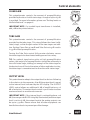
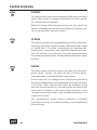
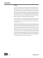
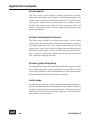
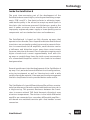
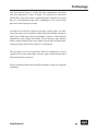
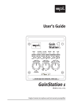
User’s Guide
EAN GAI
CL 22 2426N
19 21
18
16
15
14
13
12
11
10
Gain
Station
24.5
2.5
2.5
dB
Off
LIMITER
Fet Off Peak
2
26
OUTPUT
dB
2.5
PHANTOM
48V
Off
LIMITER
b
tO e+
ff
Fet Off Peak
3
26
OUTPUT
PHANTOM
-9
-12-10 -8 -6
-5
-14
-2.5
-16
0
-18
-20
2
3.5
-22
5
-24
5.5
-25
-26
6
dB
24.5
48V
Off
LIMITER
Fet Off Peak
4
Rev.
2.5
26
OUTPUT
dB
24.5
PHANTOM
48V
Off
LIMITER
2.5
25.5
25.8
b
tO e+
ff
Fet Off Peak
5
dB
24.5
PHANTOM
48V
Off
LIMITER
2.5
Fet Off Peak
6
dB
6
4
24.5
PHANTOM
48V
Off
LIMITER
Fet Off Peak
7
Made in Germany
Class
lass A
60-Volt Amplifiers
Rev.
IMPED. Ω
25 dB 200 1.2k 10k
2.5
25.5
25.8
1
26
OUTPUT
PHASE
Nor.
0
21
22
23
-30
24
12
9
7.5
25.5
25.8
b
tO e+
ff
-9
-12-10 -8 -6
-5
-14
-2.5
-16
0
-18
-20
2
3.5
-22
5
-24
5.5
-25
-26
6
SOURCE
Hi Z
Mic
29
32
35 Clip
HI PASS
38
50
Off
41
Hz
46 18
54
63
9
BE GA
TU 16 18 20 IN
Rev.
IMPED. Ω
25 dB 200 1.2k 10k
1
26
OUTPUT
-9
-12-10 -8 -6
-5
-14
-2.5
-16
0
-18
-20
2
3.5
-22
5
-24
5.5
-25
-26
6
19 21
18
16
15
14
13
12
11
10
PHASE
Nor.
0
21
22
23
-30
24
12
9
7.5
6
4
EAN GAI
CL 22 2426N
SOURCE
Hi Z
Mic
29
32
35 Clip
HI PASS
38
50
Off
41
Hz
46 18
54
63
9
BE GA
TU 16 18 20 IN
Rev.
IMPED. Ω
25 dB 200 1.2k 10k
1
25.5
25.8
b
tO e+
ff
-9
-12-10 -8 -6
-5
-14
-2.5
-16
0
-18
-20
2
3.5
-22
5
-24
5.5
-25
-26
6
6
4
19 21
18
16
15
14
13
12
11
10
PHASE
Nor.
0
21
22
23
-30
24
12
9
7.5
IMPED. Ω
25 dB 200 1.2k 10k
1
25.5
25.8
1
25.5
25.8
b
tO e+
ff
-9
-12-10 -8 -6
-5
-14
-2.5
-16
0
-18
-20
2
3.5
-22
5
-24
5.5
-25
-26
6
BE GA
TU 16 18 20 IN
PHASE
Nor.
0
21
22
23
-30
24
12
9
7.5
6
4
EAN GAI
CL 22 2426N
SOURCE
Hi Z
Mic
29
32
35 Clip
HI PASS
38
50
Off
41
Hz
46 18
54
63
9
b
tO e+
ff
Tu e
F
1
PHANTOM
48V
Rev.
IMPED. Ω
25 dB 200 1.2k 10k
19 21
18
16
15
14
13
12
11
10
Tu e
F
Fet Off Peak
2.5
1
26
OUTPUT
24.5
EAN GAI
CL 22 2426N
SOURCE
Hi Z
Mic
29
32
35 Clip
HI PASS
38
50
Off
41
Hz
46 18
54
63
9
BE GA
TU 16 18 20 IN
PHASE
Nor.
0
21
22
23
-30
24
12
9
7.5
6
4
19 21
18
16
15
14
13
12
11
10
Tu e
F
25.5
25.8
b
tO e+
ff
-9
-12-10 -8 -6
-5
-14
-2.5
-16
0
-18
-20
2
3.5
-22
5
-24
5.5
-25
-26
6
BE GA
TU 16 18 20 IN
Rev.
IMPED. Ω
25 dB 200 1.2k 10k
EAN GAI
CL 22 2426N
SOURCE
Hi Z
Mic
29
32
35 Clip
HI PASS
38
50
Off
41
Hz
46 18
54
63
9
Tu e
F
dB
Off
LIMITER
24.5
Tu e
F
PHANTOM
48V
19 21
18
16
15
14
13
12
11
10
PHASE
Nor.
0
21
22
23
-30
24
12
9
7.5
6
4
EAN GAI
CL 22 2426N
SOURCE
Hi Z
Mic
29
32
35 Clip
HI PASS
38
50
Off
41
Hz
46 18
54
63
9
BE GA
TU 16 18 20 IN
Rev.
IMPED. Ω
25 dB 200 1.2k 10k
1
26
OUTPUT
24.5
Tu e
F
b
tO e+
ff
-9
-12-10 -8 -6
-5
-14
-2.5
-16
0
-18
-20
2
3.5
-22
5
-24
5.5
-25
-26
6
6
4
19 21
18
16
15
14
13
12
11
10
PHASE
Nor.
0
21
22
23
-30
24
12
9
7.5
25.5
25.8
1
Tu e
F
Ultra fast wideband
Input Amplifiers
Rev.
IMPED. Ω
25 dB 200 1.2k 10k
EAN GAI
CL 22 2426N
SOURCE
Hi Z
Mic
29
32
35 Clip
HI PASS
38
50
Off
41
Hz
46 18
54
63
9
BE GA
TU 16 18 20 IN
PHASE
Nor.
0
21
22
23
-30
24
12
19 21
18
16
15
14
13
12
11
10
Tu e
F
Discrete High-Gain Preamplifier
BE GA
TU 16 18 20 IN
9
7.5
6
4
EAN GAI
CL 22 2426N
SOURCE
Hi Z
Mic
29
32
35 Clip
HI PASS
38
50
Off
41
Hz
46 18
54
63
9
POWER
26
OUTPUT
PHANTOM
-9
-12-10 -8 -6
-5
-14
-2.5
-16
0
-18
-20
2
3.5
-22
5
-24
5.5
-25
-26
6
dB
48V
Off
LIMITER
Fet Off Peak
8
Model
2388
GainStation 8
Model 2383
Eight channel microphone and instrument preamplifier
User’s Guide GainStation 8
Model 2383
Version 1.0 – 6/2003
Designer: Ruben Tilgner
This user's guide contains a description of the product. It in
no way represents a guarantee of particular characteristics
or results of use. The information in this document has been
carefully compiled and verified and, unless otherwise stated
or agreed upon, correctly describes the product at the time of
packaging with this document.
Sound Performance Lab (SPL) continuously strives to improve
its products and reserves the right to modify the product
described in this manual at any time without prior notice. This
document is the property of SPL and may not be copied or reproduced in any manner, in part or fully, without prior authorization
by SPL.
SPL electronics GmbH
Sohlweg 55
41372 Niederkruechten
Germany
Tel. +49 (0)2163 983 40
Fax +49 (0)2163 983 420
Email: [email protected]
www.soundperformancelab.com
© 2003 SPL electronics GmbH. All rights reserved. Names of other companies
and their products are trademarks of their respective owners.
2
GainStation 8
Contents
Introduction ..................................................................
4
Before you begin
7
..........................................................
Rear panel/connections ................................................ 8
Wiring ....................................................................... 8
General advices ......................................................... 9
Connectors and switches ........................................... 10
Control elements ..........................................................
Clean Gain, Tube Gain, Output Level ..........................
Source, Hi Pass, Phase ..............................................
Imped. Ω, Phantom ....................................................
Limiter .......................................................................
Power LED, LED Level Display ......................................
11
11
12
13
14
15
Operation ..................................................................... 16
Setting levels on the GainStation 8 ............................. 16
Limiter ....................................................................... 18
Application examples ...................................................
Vocals/speech
.........................................................
Acoustic instruments/orchestra ................................
Acoustic guitar with pickup .......................................
Guitar amps
.............................................................
Electric Bass
............................................................
Keyboards/samplers/drum machines ........................
Tube distortions with GainStation 8 ...........................
Drums/Snare-Drum ..................................................
Kick-Drum ................................................................
Toms ........................................................................
Overhead .................................................................
Technology
19
20
20
20
20
21
21
21
22
22
22
22
................................................................... 23
External power supply ................................................... 26
Technical Specifications
Dimensions/weight
................................................ 27
....................................................... 28
Options/Information on Lundahl input transformers ........ 28
Warranty
...................................................................... 29
GainStation 8
3
Introduction
Input makes all the difference.
Modern audio production relies increasingly on digital systems
for recording and mixing processes (DAW‘s, digital consoles
etc.). The advantages of digital audio are manifold and include
affordable storage, comfortable editing, recall capabilities and
automation. On the downside, digital systems still do not
offer the same audio qualities and sound characteristics of
high-end analog equipment. Especially digital equalizers and
other aspects of the mixing domain cannot compete with the
open, transparent sound of the best analog gear. So today
more than ever, your input signal has to sound as good as
possible—the quality of your original tracks will largely define
the end result. Lifeless or dynamically lacking signals are often
over-processed with EQ, compression and other effects in an
attempt to compensate—often an extremely tedious process
in the digital domain that doesn‘t always produce the desired
results.
Attacking this problem on the preamplification front, with the
goal of noticeably improving a signal and sending it along its
path with a healthy foundation, requires a great deal of thought
and engineering effort. To this end, the GainStation 8 employs
technologies that not only satisfy test equipment, but also—and
most importantly—the user. Components and circuits were carefully chosen and designed on the basis of extensive measurements and listening tests. In short, developing the GainStation 8
was a major undertaking that required immense amounts of
time and experience.
4
GainStation 8
Introduction
Main technical features of the GainStation 8
• Custom-designed and built, fully discrete, class A op-amps (no
off-the-shelf stuff here). The GainStation‘s op-amps feature
60-Volt operating voltage—twice as high as most common
op-amps—for an incredible dynamic range.
• An extremely high amplifier slew rate of 200 V/microsecond,
ensuring clean transmission of high-frequency signal portions
and rapid transients with virtually no cut-off.
• An almost entirely DC-coupled signal path, making signaldegenerating condensers unnecessary.
• An optimized layout guarantees the shortest possible signal
paths, while generously proportioned grounding surfaces
ensure low impedance and maximum shielding.
• All switching functions are handled by encapsulated relays
with gold-plated contacts.
• All resistors are within 0.1% tolerance and were selected after
extensive listening tests.
• A no-compromise power supply with extensive additional
shielding and seven separately wound and regulated voltages. The power supply is of primary importance to audio
quality; its importance should not be underestimated.
• A tube stage utilizing premium MKP foil condensers and a
select 12 AX7 LPS tube for clear, dynamic audio.
GainStation 8
5
Introduction
This cutting-edge technology ensures that signals recorded
with the GainStation 8 have more presence and substance and
will easily cut through a mix even at lower levels. Extremely
low-frequency signals are tight and transparent with clear intonation. Percussive transients are interpreted more precisely,
which leads to a clearer rhythmic content and in turn a more
solid rhythmic performance and perception.
If the GainStation 8 is used as a preamp, musicians will immediately notice that they hear and feel what they are playing
much better, which leads to improved playing and a better
recording. The track will have more punch and dynamics, greatly
improved presence and almost palpable detail. In short, the
instrument sounds incredibly authentic and alive. Beta-tests
with the GainStation 8 showed that all instrumentalists enjoyed
playing more and in many cases were truly amazed at what their
trusty instrument was capable of.
Given this improvement in the input signal, one is much less
inclined to equalize and compress—in many cases you will probably find that you can do without additional processing, which
not only saves an enormous amount of time and processor
power, but also has an extremely positive effect on the final
result.
The GainStation 8 itself offers effective sound-shaping capabilities at recording, most notably via the tube stage, which can
be completely bypassed or continuously added to the preamp
circuit, allowing everything from extremely subtle “warmth“ to
a very noticeable tube saturation effect. The integrated limiter
can be used to protect an internal or external AD converter
from clipping, or for example to add punch to drum tracks,
which in turn reduces or in many cases even eliminates the
need for subsequent compression. Put simply, the more tracks
are recorded with the GainStation 8, the more solid and transparent—and easier to mix—the entire recording will be.
6
GainStation 8
Before you begin
It makes good sense to think about where you place your
GainStation 8 before connecting it. It should be positioned so
that you can easily reach it, but there are other considerations.
Try not to place it near heat sources or in direct sunlight,
and avoid exposure to excessive vibrations, dust, heat, cold
or moisture. It should also be kept away from transformers,
motors, power amplifiers and digital processors.
IMPORTANT NOTE: When installing the GainStation 8 in a rack,
please be sure to leave about a unit (1.5 to 2 inches) of space
above it to ensure sufficient circulation. If possible, install the
unit in a rack with other analog units to avoid interference
from digital units, such as clock frequencies. We recommend
covering the empty rack space above the GainStation 8 with a
blind panel to reduce the amount of dust and debris sucked into
the unit by its fan. The fan side of the housing must always be
kept free.
IMPORTANT NOTE: Never disconnect the GainStation 8 from its
external power supply while the unit is switched on. Always turn
it off first and wait at least one minute, so that all current can
dissipate, before disconnecting the multipin connector. Failure
to do so can cause severe damage to components.
In addition, please:
• Do not open the case. You may risk electric shock and damage
to your equipment.
• Leave repairs and maintenance to a qualified service technician. Should foreign objects fall inside the case, contact your
authorized dealer or support person.
• To avoid electric shock or fire hazards, do not expose your
unit to rain or moisture.
• In case of lightning, unplug the unit.
• Always unplug the cable by pulling on the plug only; never
pull on the cable.
• Never force a switch or knob.
• Use a soft, lint-free cloth to clean the case. Avoid cleaning
agents as they may damage the unit.
GainStation 8
7
Made in Germany
VOLTAGE/FUSE
2
1
110 V – 120 V/ 60 Hz
3
3.2 A slow blow
110 V – 120 V/ 60 Hz:
1.6 A slow blow
220 V – 240 V/ 50 Hz:
FUSE RATING
AC MAINS INPUT
1 23 03 21
Gain Station 8
POWER SUPPLY
DC INPUT
220 V – 240 V/ 50 Hz
PUSH
PUSH
INSTR. IN
(UNBAL.)
GND LIFT
DC OUTPUT
OUT 2
(BAL. )
PUSH
7
OUT 2
(BAL. )
PUSH
2383-PSU
3830123-P
SERIAL NUMBER
1
2
MADE IN GERMANY
Sound Performance Lab
Niederkrüchten
Germany
Model 2383-PSU
Power Supply Unit
for GainStation 8
OUT 1
(BAL. )
MIC
INPUT
INSTR. IN
(UNBAL.)
Pin wiring
XLR-Mic Input
1=GND 2=hot (+) 3=cold (-)
DISCONNECT MAINS BEFORE REMOVING COVER.
NO USER SERVICEABLE PARTS INSIDE.
THIS EQUIPMENT MUST BE EARTHED.
TO REDUCE RISK OF FIRE OR ELECTRIC SHOCK DO
NOT EXPOSE THIS UNIT TO RAIN OR MOISTURE.
WARNING
AVIS: RISQUE DE CHOC ÉLECTRIQUE - NE PAS OUVRIR
RISK OF ELECTRIC SHOCK
DO NOT OPEN
CAUTION
OUT 2
(BAL. )
OUT 1
(BAL. )
MIC
INPUT
8
3
INSTR. IN
(UNBAL.)
OUT 2
(BAL. )
INSTR. IN
(UNBAL.)
OUT 1
(BAL. )
MIC
INPUT
5
INSTR. IN
(UNBAL.)
OUT 2
(BAL. )
PUSH
INSTR. IN
(UNBAL.)
OUT 1
(BAL. )
MIC
INPUT
3
OUT 2
(BAL. )
1
INSTR. IN
(UNBAL.)
OUT 1
(BAL. )
MIC
INPUT
Tip=hot(+) Ring=cold(-) Sleeve=GND
Pin wiring TRS connectors
Instruments,
line level signals
(unbalanced)
INSTR. IN
(UNBAL.)
OUT 1
(BAL. )
MIC
INPUT
2
JACK Wiring (Unbalanced): Tip = High (+)/ Sleeve = GND
OUT 2
(BAL. )
Converters, recorders,
mixing console (balanced)
OUT 2
(BAL. )
OUT 1
(BAL. )
MIC
INPUT
4
JACK Wiring (Balanced): Tip = High (+)/Ring = Low (–)/ Sleeve = GND
PUSH
Pin wiring
XLR Output
1=GND 2=hot(+) 3=cold(-)
OUT 1
(BAL. )
MIC
INPUT
6
PUSH
XLR Wiring: Pin 1 = GND/ Pin 2 = High (+)/ Pin 3 = Low (–)
PUSH
8
PUSH
Microphone (alternatively also balanced line level signals)
Rear panel/connections
Wiring
GainStation 8
Rear panel/connections
General advices
Again, while the GainStation 8‘s housing is EMV-proof and
protects against HF-interference, placement of the unit is
very important since it amplifies microphone signals as well
as other unwanted signals. Thus, it is extremely important
that the external power supply not be positioned near the
GainStation 8.
IMPORTANT: Adjust the voltage setting on the back of the
external power supply so that it corresponds with the power
conditions. Before connecting the GainStation 8 or any other
equipment turn off all power.
VOLTAGE/FUSE
220 V – 240 V/ 50 Hz:
1.6 A slow blow
110 V – 120 V/ 60 Hz:
110 V – 120 V/ 60 Hz
The following graph shows the correct wiring for connecting
unbalanced signals to the balanced XLR connectors:
Output
balanced
unbalanced
2
1
2
1
3
3
1=GND
2=hot (+)
3=cold (-)
The Line Input connector is designed for unbalanced signals
only.
The TRS output connector (see „Analog Outputs“, page 10) can
be operated both with balanced and unbalanced wiring. Simply
use a mono 1/4" plug for unbalanced operation.
GainStation 8
FUSE RATING
220 V – 240 V/ 50 Hz
9
3.2 A slow blow
Rear panel/connections
PUSH
MIC INPUT
MIC
INPUT
Dynamic, condenser or tube microphones can be connected to
the Mic Input. The 48 V switch provides the phantom power
necessary for some microphones (see also „Control elements/
Phantom“ on page 13).
The MIc Input can also be used as a balanced connection for
professional audio equipment with a maximum output level of
+20 dBu. The Clean Gain already delivers 10 dB of minimum
preamplification, this leaves you with 4 dB of headroom.
IMPORTANT NOTE: Always switch the phantom power (48 V)
off before connecting anything other than phantom-powered
condenser microphones.
INSTRUMENT/LINE INPUT
INSTR. IN
(UNBAL.)
The Instr. In is for electric guitars and basses or other high-impedance, line-level signals such as keyboards, samplers, drum
machines etc. with unbalanced outputs. If a balanced connector
(TRS) is inserted, the ring of the plug is automatically connected
to the ground to ensure proper unbalanced operation.
ANALOG OUTPUTS 1/2
OUT 1
(BAL. )
OUT 2
(BAL. )
The preamplified output signal is fed to the balanced Analog
Outputs. Since the XLR and 1/4" TRS connectors are wired in
parallel, an unbalanced connection at one connector will cause
the other connector to operate unbalanced, e.g. if a mono 1/4"
plug is inserted into the 1/4" jack, the corresponding XLR socket
will also operate unbalanced.
IMPORTANT NOTE: The output connectors can deliver an output
level of up to +34 dBu. Please ensure that all other equipment
can handle these levels to prevent possible damage.
10
GainStation 8
Control elements
CLEAN GAIN
This potentiometer controls the amount of preamplification
provided by the class A solid-state stage. A range of up to +63 dB
is provided. For more information, please see “Setting levels on
the GainStation 8“ on page 16.
NG
LEA 22 24AIN
C 19 21
18
16
15
14
13
12
11
10
26
29
32
35
38
41
46
54
63
dB
Mic: +7dB
w/transformer
IMPORTANT NOTE: If a Lundahl input transformer is installed,
add 7 dB to the printed values.
TUBE GAIN
9
22
23
24
7.5
6
4
24.5
25
2.5
25.5
25.8
1
b
tO e+
ff
Tu e
F
This potentiometer controls the amount of preamplification
provided by the tube stage. This stage follows the clean (solidstate) stage, so that the gain values of the two stages are additive. Setting Clean Gain at 20 dB and Tube Gain at 15 dB results
in 35 dB of total preamplification.
BE18GAIN
TU
12 16 20 21
dB
26
Turning the Tube Gain control fully counter-clockwise causes
the tube stage to be deactivated and bypassed via a relay.
TIP: For optimal signal-noise ratios at high preamplification
values, the majority of preamplification should be achieved via
the solid-state stage, adding just enough of the tube stage for
the desired sound. Due to the nature of tubes and tube circuitry,
the tube stage is somewhat noisier than the solid-state stage.
TPUT LEV
U-12-10 -9 -8 -6 E
-5
-14
-2.5
-16
0
-18
-20
2
3.5
-22
5
-24
5.5
-25
-26
6
This potentiometer adapts the output level to devices following
in the chain or to the converter. At 0 dB the output level is equal
to the internal level indicated by the LED display. The OUTPUT
LEVEL control allows an additional 6 dB of amplification or 26
dB of reduction. The output level control is post-limiter to allow
maximum levels to an external converter.
dB
IMPORTANT NOTE: If the internal level is noticeably above +18
dB (the orange +18 dB LED is brightly illuminated) and the output
level is set to +6 dB, the output level at the analog outputs can
be up to +34 dBu. Please ensure that all other equipment can
handle these levels to prevent possible damage.
GainStation 8
L
O
OUTPUT LEVEL
11
Control elements
SOURCE
SOURCE
Hi Z
Mic
This switch allows you to select between the Mic and Instrument
inputs. Both inputs can remain connected at all times, regardless of which input is selected.
When first thrown after powering up the unit, this switch can
cause a noticeable pop due to the discharge of residual current.
This is normal and no cause for concern.
HI PASS
HI PASS
Off
50
Hz
This switch activates the integrated high-pass filter, which operates at a 50-Hz center frequency and 12 dB/octave (often called
a “rumble filter“). The filter is entirely passive, avoiding additional active circuitry that could potentially degrade the signal,
and cuts 6 dB pre- and 6 dB post-solid-state preamplification
to prevent the amplification of unwanted low-frequency signal
portions.
PHASE
PHASE
Nor.
Rev.
The phase reverse function reverses the polarity of the microphone signal, “turning“ the phase by 180° to correct phaseinverted signals caused by multiple signal sources.
A voice-over artist, for example, hears himself during recording
through the headphones and simultaneously through the bones
in his head. Phase inversion will cause an unnatural sound
and even minimal variations in distance to the microphone will
cause drastic variations in the sound. Phase inversion is also
commonly encountered when using multiple microphones on a
single sound source.
The GainStation 8‘s phase reverse switching is achieved
passively via a relay, pre-preamplification, to avoid additional
active circuitry.
12
GainStation 8
Control elements
IMPED. Ω
IMPED. Ω
200 1.2k 10k
This 3-way switch allows you to select between three input
impedances for the Mic Input. In general, higher impedances
increase levels and emphasize high frequencies, while mids and
bass frequenices are dampened. Conversely, a lower impedance
causes lower levels and emphasizes bass and mid frequencies.
The Imped. Ω-Wert does not have to be equivalent to the output
impedance of the microphone. We recommend the highest
impedance setting as starting position (10.000 Ohm). Now it
must be evaluated acoustically, if lower settings are delivering
better results.
PHANTOM
48V
PHANTOM
The GainStation 8 provides 48 Volt phantom power for microphones requiring external current (generally condenser microphones). Such microphones are dependent upon a clean, consistent and noise-free power supply for optimal operation and
audio quality. The GainStation 8 continuously delivers precisely
48 V and a maximum of 14 mA, which will power all microphones.
IMPORTANT NOTE: All microphones with balanced, ground-free
outputs, including tube microphones, can be used with the
phantom power activated. First connect the microphone to the
GainStation 8, then activate the phantom power. When finished,
first deactivate the phantom power and wait at least 30 seconds
before disconnecting the microphone to allow residual current
to discharge.
Phantom power should only be activated when using microphones that require it. Please be sure to deactivate phantom
power with all other microphones. Unbalanced microphones
may only be used with phantom power deactivated.
The 48V LED illuminates to indicate activated phantom power.
When deactivating phantom power, it can take several seconds
for the LED to go out, since the 48 V current dissipates rather
slowly. When changing microphones, you should wait until the
LED is completely dark before re-patching.
GainStation 8
13
Off
Control elements
LIMITER
LIMITER
Fet Off Peak
The GainStation 8 offers two types of output level limiting:
Peak and FET. The limiter is pre-output level control, so that
the limited signal can be optimally adapted to an external
converter.
The peak limiter operates with special diodes that convert signal
peaks into a type of saturation. Depending on the signal, this
allows levels to be effectively and subtly limited. This type of
limiting works very quickly, reliably limiting even microsecondlong transients, and is very effective for drums and percussion.
The peak limiter also enables maximum loudness. Operation is
displayed via the Limit LED.
The FET limiter is additionally available when the tube stage is
activated. The FET circuit operates with a Field Effect Transistor
(FET), which is connected to the tube and enables—always in
conjunction with the peak limiter—a reduction of signal amplitude. Thus this limiter works in a similar fashion to a compressor,
which makes it very effective for signals that undergo unforeseeable level changes (i.e. vocals, speech, guitar, bass, piano
etc.) and where minimum loss in signal quality is desired. The
peak limiter is always active post-FET limiter to ensure reliable
protection. The Limit LED also displays the operation of the FET
limiter (always somewhat more calmly than with peak limiting).
IMPORTANT NOTE: If the tube stage is deactivated while FET
limiting is active, the LED will continue to display in FET limiting
mode.
For more information on using the limiters please see page 18,
”Limiter”.
14
GainStation 8
Control elements
POWER
POWER
Switches the unit on or off. The switch illuminates with delay,
because it is fed by the 250 V anode power – don’t panic.
If the tube stage is active when the unit is switched on, it can
take several seconds before a signal can be heard—this time is
necessary for the tube to reach operating temperature.
IMPORTANT NOTE: Never disconnect the GainStation 8 from its
external power supply while the unit is switched on. Always turn
it off first and wait at least one minute, so that all current can
dissipate, before disconnecting the multipin connector. Failure
to do so can cause severe damage to components.
LED LEVEL DISPLAY
Clip
18
The level display shows the peak level before output level
control. A special circuit allows the LED‘s to vary in brightness
to display in-between values. The -30 LED illuminates weakly at
-30 dB and reaches full brightness at 0 dB. The 0 dB LED illuminates weakly at 0 dB and reaches full brightness at +9 dB and so
on.
9
0
-30
dB
The CLIP LED operates post-CLEAN GAIN stage and displays
clipping at this point in the signal path. It will not react to tube
saturation in the tube stage, since this can be a desired effect.
GainStation 8
15
Operation
In spite of its quality and flexibility, the GainStation 8‘s transparent user interface allows quick, intuitive operation. The
unit is suited for a wide variety of applications. The following
sections will provide an overview of the most important operational concepts and several application examples.
Setting levels on the GainStation 8
Start with the limiter switched off. With a representative signal
present at either the MIC or HI-Z input, set the desired combination of Clean and Tube Gain so that the 9 dB LED illuminates
brightly. When this LED illuminates weakly, you have 9 dB of
gain. When brightly lit, you have 15-17 dB, which still leaves
you with a good 9 dB of headroom (in the range displayed by
the orange 18 dB LED) before clipping. The orange LED illuminates dimly at 18 dB and brightly at around 26 dB. The red Clip
LED should never illuminate—this indicates clipping in the clean
stage, which generally should be avoided, as it will lead to
distortion of the solid-state circuitry. (You may find this desirable in some rare cases—we had lots of fun creating heavily
distorted guitar sounds…)
The Clip LED does not display high amplification levels in the
tube stage that could lead to distortion. The GainStation 8 intentionally allows tube saturation, since tube distortion—contrary
to transistor distortion—is often a desirable effect.
Once you have adjusted the gain levels as described above,
use the Output Level control to set the optimal output level for
subsequent devices in the chain.
IMPORTANT NOTE: The Output Level control should not be set
above 0 dB when working with high internal levels of more than
18 dBu. Otherwise, extremely high output voltages of up to
34 dBu (approximately 38 Veff) can occur, which can damage
other equipment. Please refer to the documentation of your
other equipment regarding maximum input levels.
16
GainStation 8
Operation
Combining different amounts of clean and tube gain will create
various effects. The GainStation 8 operates virtually distortionfree with the tube stage bypassed. The sound is clean and transparent with extreme detail and very low noise. The clean stage
is ideal for most acoustic instruments, as well as jazz or classical recordings. If you activate the tube stage and increase
the gain setting slowly, you will notice that once you reach a
certain level, harmonic distortion enters the signal. The sound
becomes punchier and “fatter“, and attains more loudness. At
this setting the tube stage is still relatively noise-free, and ideal
for adding a bit of presence and liveliness to signals that may
otherwise sound dull or lifeless. This setting works very well
with stringed instruments like acoustic guitars, electric and
acoustic basses and violins, since it highlights the harmonics of
the strings.
Naturally, these effects become more pronounced as the amount
of Tube Gain is increased. The tube can be driven to full saturation to produce pronounced distortion, which can be very
effective with synthesizers, samplers and drum machines that
lack punch. Signals recorded in this fashion will generally cut
through a mix with no trouble at all.
GainStation 8
17
Operation
Limiter
To achieve the desired results with the integrated limiter, it is
important to understand its operation. The threshold value is
fixed at 20 dBu. The clean and/or tube gain settings determine
the amount of limiting, so that these settings more or less work
like a threshold control. When the limiter is activated, it levels
everything above 20 dBu. The orange 18 dB LED, which displays
this level range, varies in brightness depending on limiting. The
actual amount of limiting is displayed by the Limit LED, which
becomes brighter as more level reduction is applied.
The peak limiter sounds different with the tube stage activated,
since leveling occurs somewhat asymmetrically with the tube in
the signal path, so that the negative half-wave is leveled with a
much flatter curve.
To determine the ideal limiter setting for the internal converter,
activate the peak limiting mode and adjust the Clean and/or
Tube Gain to a setting well above your working level, so that
the Limit LED illuminates brightly. Then reduce the Output Level
until the AD OVL LED goes out. Now your gain levels can be
returned to their normal settings and the limiter can be switched
into FET mode if desired. The same method should be used with
an external converter, except that in this case the external unit‘s
clip LED is used for calibration. If you are only using the FET
limiter and your program material contains few fast transients,
the output level can be set somewhat higher.
18
GainStation 8
Application examples
The advent of digital recording and the fact that more and more
material remains in the digital domain from start to finish have
raised demands on preamplifiers. The GainStation 8 is predestined to act as a premium recording front end, ensuring that
signals of all kinds are preamplified with the highest quality,
whether as an alternative to existing console preamps or as a
stand-alone solution between source and A/D converter.
The quality of your recordings has a major influence on the
subsequent mixing process – good recordings require less
processing in later stages. Improved transparence and intelligibility can be achieved with less equalization and compression
if the signals are recorded optimally, often allowing individual
signals to be mixed at lower levels without compromising their
presence.
The GainStation 8 can also effectively improve live recordings
and mixes. Particularly in live situations, microphone signals
must often travel extremely long distances to reach the FOH or
mobile console, resulting in high cable capacities, which can
degrade and color the sound. In this application, we recommend
placing the GainStation 8 on stage. This allows for short cable
runs to the preamps, whereas the GainStation‘s gain structure
and fast output stages can easily drive the longer runs that
ensue.
The following section, while not attempting to represent a
complete guide or answer all questions, provides several operational tips for various instruments.
GainStation 8
19
Application examples
Vocals/speech
The tube stage is well suited for adding presence to vocals.
Exercise caution when setting levels, particularly with the clean
stage, since vocals can be extremely dynamic. The FET limiter
can be very helpful here to level peaks in a subtle, musical
fashion and ensure safe levels for AD conversion. Once the
limiter is properly set (see ”Limiter”, page 20), tube gain can be
added as required.
Acoustic instruments/orchestra
The tube stage should be used very sparingly, if at all, when
miking/recording orchestras or acoustic instruments, to ensure
the highest possible S/N ratio. Levels should be set with the
utmost care, since distortion and clipping are easily heard and
absolutely undesirable in classical and most acoustic recordings. In general, the limiter should only be used to protect the
A/D converter or digital recorder.
Acoustic guitar with pickup
A combination of clean and tube stages will deliver good results
here. Lower tube gain settings between 1 and 9 dB will result
in a very acceptable S/N ratio. Moderate use of the peak limiter
will provide the best protection against clipping.
Guitar amps
As with acoustic guitars, combining the clean and tube stages is
especially effective when miking guitar amps. Higher Tube Gain
settings result in more punch and loudness. The more distorted
the guitar sound, the less limiting is required, since the distortion process levels dynamics.
20
GainStation 8
Application examples
Electric Bass
If an electric bass is directly connected to the instrument input, a
combination of clean and tube stages is usually best. In the case
of extreme dynamics, the FET limiter will deliver excellent results
and a tight, punchy bass sound that usually needs no additional
compression.
Keyboards/samplers/drum machines
Electronic sound sources allow you to fully utilize the
GainStation 8‘s potential. The clean stage is excellent for clear,
glassy sounds and pads, and a combination of clean and tube
stages for most other sounds. The more dynamic the material,
the more effectively you can utilize the limiter.
Tube distortions with GainStation 8
The GainStation can be a great creative tool for creating distortion effects for suitable instruments and loops. Try using very
high tube gain settings, so that the 18 dB LED is constantly illuminated. Increasing the clean gain will feed more level to the
tube stage, intensifying the tube saturation effect.
Activating the peak limiter will add a different type of distortion
with more overtones. The FET limiter will not add distortion,
but will create “hard limited” sounds with an extreme loudness
effect.
GainStation 8
21
Application examples
Drums/snare drum
Exercise caution when setting levels to avoid clipping. Drums
are notorious for fast, powerful transients that can easily add
10 dB to the average level. In addition, few drummers (or any
musicians, for that matter) are so disciplined that they don‘t
play louder during a take or concert than they do during sound
check. Experiment to see whether or not you like the sound of
the tube stage and in what proportion. It‘s definitely a good idea
to use peak limiting to protect converters and/or other equipment and prevent unwanted distortion (see “Limiter”, page 20).
In FET mode, the limiter may be more audible than you‘d like it
to be when used on drums.
Bass drum
Here pretty much the same applies as for snare drum. The peak
limiter may tend to accentuate the attack or “click” of the bass
drum, which can lead to undesirable sound variations with less
disciplined drummers.
Toms
Level setting is not quite as critical with toms. Moderate use of
the FET limiter will provide pleasant yet effective leveling.
Overheads
Using the tube stage on overheads can give the entire drum set
extra punch and presence—don‘t worry if the 18 dB LED illuminates brightly in this case. Higher tube gain levels will increase
the punch and loudness effect. The FET limiter is an additional
creative tool on overheads.
22
GainStation 8
Technology
Inside the GainStation 8
The most time-consuming part of the development of the
GainStation 8 was searching for, selecting and matching components, PCB‘s and IC‘s. One decisive factor in achieving impeccable audio quality is the refusal to accept any weak spots in
the chain—the insistence upon each link being as good as the
next. It makes no sense to use a world-class op-amp with an
improperly engineered power supply or lower-quality passive
components such as standard resistors and condensers.
The GainStation 8 is based on fully discrete op-amps that
operate in class A mode. Class A operation dictates that both end
transistors are constantly conducting current to prevent distortion. In conventional class B amplifiers, each transistor carries
a half-wave, and distortion occurs every time current moves
from one transistor to the next. Class A operation requires much
higher closed-circuit current—approximately 6 mA with this
op-amps or roughly three times the total current consumption
of a conventional amplifier—which in turn leads to increased
heat generation.
Several months went into the development of the GainStation 8
op-amp. First, we tested several different circuit configurations,
using test equipment as well as listening tests with a wide
variety of program material. It became more and more apparent
that less complicated circuits provided better audio results.
The GainStation 8‘s input differential amplifier utilizes an extremely low-tolerance, thermal-coupled matched transistor pair in
a single casing. This prevents deviances between the transistors to ensure minimal THD (total harmonic distortion) even
at various temperatures. The resistors in the initial differential
amplifier are connected to a secondary differential amplifier—
also based on a matched transistor pair—that handles current
conversion.
GainStation 8
23
Technology
An output stage, which also operates in class A mode with over
6 mA of closed-circuit current, functions as a current amplifier.
The transistors and resistors utilized also had an enormous
effect on the audio quality. To facilitate selection, we assembled several models and subjected them to extensive listening
tests. All this trouble more than paid off: the final GainStation 8
op-amp has a slew rate of over 100V/µs—several times faster
than industrial op-amps. This is an absolute prerequisite for
clean, transparent and dynamic audio. Transients are depicted
with unparalleled accuracy, resulting in an open, airy and realistic sound.
The clean stage is based on a fully discrete, balanced instrument amplifier and also operates in class A mode. The special
circuit configuration ensures consistent frequency response at
virtually every gain setting. With its slew rate of over 200 V/µs, it
is able to amplify fast transients and extremely high frequencies
with almost no distortion. An op-amp subsequently converts
the instrument amplifier‘s output signal into an unbalanced
signal, which is fed to the tube.
The tube type—a Sovtek® 12 AX7 LPS—was also selected after
extensive measurements and listening tests. This tube type
delivers an open, transparent sound, excellent noise values
and is especially reliable. A generously proportioned 2.2 µF
WIMA-MKP decoupling capacitor is utilized to ensure clean,
punchy low frequency response. An impedance converter adapts
the tube‘s high-impedance signal to the output stage, which
also utilizes fully discrete op-amps and can easily drive extreme
cable lengths. Coupling condensers were used as sparingly as
possible to avoid their inherent disadvantages such as diffuse
sound, slurring and loss of dynamics. Instead, servo circuits
were utilized to eliminate DC artifacts.
24
GainStation 8
Technology
The Instrument Input is a fully discrete impedance converter
that also operates in class A mode. It is based on a low-noise
field effect transistor that is especially well suited to this task
due to its extremely high input impedance. The signal then
passes to the clean gain stage.
In order to ensure the shortest possible signal paths, all switching functions are handled by optimally positioned, encapsulated, gas-filled relays with gold-plated contacts—the switches
themselves only trigger the relays. Since resistors also greatly
affect audio quality, the entire audio signal path utilizes painstakingly selected resistors with 0.1 % tolerance.
The op-amp circuits use premium FKP foil condensers, which
sound much more open than ceramic types and provide more
natural dynamic response.
All circuit boards have oversized grounding surfaces for optimal
shielding.
GainStation 8
25
External power supply
In the case of the power supply, no expense was spared. After
all, the power supply is one of the primary factors in the audio
quality and overall sound of any device. Just like the best coffee
beans in the world will not produce a good cup of coffee with
poor water, the best circuits can‘t produce a great sound with
unreliable, inconsistent current.
In order to provide optimal current, the GainStation 8 was
outfitted with an external power supply. Properly installed,
transformer hum and interference should never be an issue and
the unit should deliver clean, clear audio.
The 185 VA transformer is generously proportioned to ensure
plenty of power in any situation and proper current for the
various circuits. Further interference rejection is provided by a
power-on relay, which requires only minimal current. The power
supply design keeps the GainStation‘s internal circuitry free
from AC power, which could negatively influence the sensitive
preamps.
Entirely new circuit designs were developed to process the
various direct currents. The +/- 30 V current, for example, utilizes
a discrete voltage regulator with barely measurable noise. Highspeed rectifier diodes and total capacities of 53,600 mF ensure
sufficient current to process even the most powerful impulses.
In addition, most currents are stabilized using 400 V/100 nF MKP
foil condensers to ensure plenty of current for fast transients.
48 V phantom power is also processed using discrete, low-noise
voltage regulators and fed directly to the microphone conductors through two resistors.
Last but not least, the +250 V anode current is regulated by a
voltage regulator to compensate for AC influences.
26
GainStation 8
Technical specifications
Frequency response (Clean Gain 30 dB, Tube Gain off, output
level 0 dB, +/- 0.5 dB):
‹1 Hz-125 kHz
Frequency response (Clean Gain 30 dB, Tube Gain off, output
level 0 dB, +/- 3 dB):
‹1 Hz-310 kHz
Frequency response (Clean Gain 30 dB, Tube Gain 1 dB, output
level 0 dB, +/- 0.5 dB):
‹1Hz-125 kHz
THD+N (Clean Gain 24 dB, Tube Gain off, output level +6 dB,
20-22 kHz, +25 dBu out):
0.00038 %
THD+N (Clean Gain 23 dB, Tube Gain 1 dB, output level +6 dB,
20-22 kHz, +25 dBu out):
0.032 %
Noise (Clean Gain 10 dB, Tube Gain off, output level 0 dB,
20-22 kHz, A-weighted):
-99.6 dBu
Noise (Clean Gain 30 dB, Tube Gain off, output level 0 dB,
20-22 kHz, A-weighted):
-94.6 dBu
Noise (Clean Gain 60 dB, Tube Gain off, output level 0 dB,
20-22 kHz, A-weighted):
-68.4 dBu
Noise (Clean Gain 20 dB, Tube Gain 10 dB, output level 0 dB,
20-22kHz, A-weighted):
-86.5 dBu
EIN (Clean Gain 60 dB, Tube Gain off, output level 0 dB, 20-22kHz,
A-weighted, 40 Ω):
128.4 dB
Dynamic response (20-22kHz, A-weighted):
›130 dB
Common Mode Rejection (Clean Gain 30 dB, Tube Gain off, 1 kHz,
Input -30 dBu, output level 0, w/o transformer):
›80 dB
Maximum Output Level:
+34 dBu
Max. Input Level (Mic Input, Hi-Z Input):
+17 dBu
Input Impedance (Instrument input):
›1 MΩ
Output impedance:
›75 Ω
Slew Rate (Clean Gain 30 dB, Tube Gain off, Output Level
+6 dB):
›40 V/µs
Phantom power:
Power consumption (w/0 AD-Converter):
GainStation 8
48 V +/-2 V
140 W
27
Dimensions/weight
Dimensions (W x H x D):
482 x 88 x 237 mm
Weight (w/o Lundahl transformer):
External power supply – dimensions:
6,3 kg
219 x 85 x 257 mm
Weight:
6,8 kg
Options
The following accessory is optionally available:
• Lundahl input transformer (upgrades after sale by authorized
service personnel or SPL only)
Information on Lundahl input transformers
Transformers have the characteristics usually associated with
other analog components like tubes or coils–they sound
“warmer”, fatter, punchier, more direct, improved presence
without boosting the top end.
One main reason for this is that transformers cancel out a large
amount of odd harmonics (those portions of an audio signal
that sound harsh to human ears).
The GainStation 8's input transformer delivers 7 dB of additional
passive gain, which must be added to the printed values.
Technical specifications are subject to change without notice.
28
GainStation 8
Warranty
SPL products are manufactured using carefully selected components and materials and state-of-the-art production technology. Every SPL product is thorough inspected and tested before
leaving the factory, including acoustic and electronic testing.
SPL warrantees the SPL 24/96 AD Converter Model 2376 to be
free of defects in materials or workmanship for a period of 24
months after the date of purchase. Should any trouble caused
by defects in materials or workmanship develop during this
period, SPL will repair or, at our option, replace the product
at no charge. Should SPL choose to replace the product, we
reserve the right to replace it with a newer model.
In order to validate your warranty, you must either return
the enclosed warranty registration card, completely filled
out, to SPL, or register your product online within 14 days
of purchase. You may register your product online at
www.soundperformancelab.com or, in the USA or Canada at
www.spl-usa.com.
The warranty period begins on the date of purchase. The
warranty is non-transferable. Repairs or replacements do not
extend the warranty period.
This warranty does not apply if:
• the product was not purchased from an authorized SPL
dealer
• repairs are required due to normal wear and tear
• the product has been abused, misused or improperly
maintained, or if repairs or alterations have been made
or attempted by any other than authorized SPL service
personnel
• the serial number has been removed or defaced
In no event shall SPL be liable for any indirect, incidental or
consequential damages from the sale or use of this product,
either during or after the warranty period.
SPL disclaims liability for any implied warranties, including
implied warranties of merchantability and/or fitness for a
specific purpose, after the warranty period.
This warranty gives you specific legal rights. You may have
other rights, which vary from country to country and state to
state. Some of the above limitations may not apply to you.
SPL electronics GmbH, 41372 Niederkruechten, Germany
GainStation 8
29
< Manual GainStation 8, Model 2383
All you need is imagination, good ears and three letters: