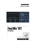
1
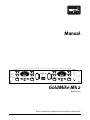
Manual
PAD
PHANTOM
VU CAL
dB
Dual Channel
Microphone,
Line &
Instrument
Preamplifier
48V
-20
Off
Off
PHASE
So
HI PASS
und
20
Hz
Rev.
50
%0
3 1 0
10 7 5
30
-10
Limit
Performance
AD OVL
FLAIR
3 5
Nor.
High
Off
Med
Off
1
Gain
dB
SOURCE
INSTR.
18
6
12
Output
24 27 29
32
35
38
41
44
49
54
60
66
TUBE AMP
dB
50 70 100
INSERT
Instr.
Line
On
Mic
Off
PAD
PHANTOM
dB
18
Off
12
0
Lab
VU
22
21
20
19
18
17
16
15
14
LIMITER
dB
Clip
48 V
-10 -9 -8
-6
-12
-5
-14
-2.5
-16
0
-18
2
-20
3.5
-22
-24
5
5.5
-25
-26
6
dB
VU CAL
dB
GoldMike
Mark 2
48V
-20
Off
Off
PHASE
So
HI PASS
und
20
Hz
Rev.
50
%0
3 1 0
10 7 5
30
-10
Limit
Performance
AD OVL
Nor.
3 5
2
dB
SOURCE
INSTR.
FLAIR
TUBE AMP
High
Off
Med
18
6
12
Discrete
Class A
Preamplifier
Stage
Output
24 27 29
32
35
38
41
44
49
54
60
66
18
Off
12
dB
50 70 100
Off
Gain
dB
0
Lab
VU
22
21
20
19
18
17
16
15
14
LIMITER
dB
Clip
48 V
INSERT
Instr.
Line
On
Mic
Off
-10 -9 -8
-6
-12
-5
-14
-2.5
-16
0
-18
2
-20
3.5
-22
-24
5
5.5
-25
-26
6
dB
Power
Model
2485
GoldMike Mk 2
Model 2485
Dual-channel microphone and instrument preamplifier
Manual GoldMike MK2
Model 2485
Version 1.2 – 12/2005
Designer: Ruben Tilgner
This user's guide contains a description of the product. It in
no way represents a guarantee of particular characteristics
or results of use. The information in this document has been
carefully compiled and verified and, unless otherwise stated
or agreed upon, correctly describes the product at the time of
packaging with this document.
Sound Performance Lab (SPL) continuously strives to improve
its products and reserves the right to modify the product
described in this manual at any time without prior notice. This
document is the property of SPL and may not be copied or reproduced in any manner, in part or fully, without prior authorization
by SPL.
SPL electronics GmbH
Sohlweg 55, 41372 Niederkruechten
Germany
Tel. +49 (0)2163 983 40
Fax +49 (0)2163 983 420
Email: [email protected]
Website: www.soundperformancelab.com
SPL USA
EMail: www.spl-usa.com
Website: [email protected]
© 2005 SPL electronics GmbH. All rights reserved. Names of other companies
and their products are trademarks of their respective owners.
2
GoldMike MK2
Contents
Introduction ...................................................................
4
Before You Begin ............................................................
5
Rear Panel/Connections .................................................
Wiring .........................................................................
General advices ...........................................................
Mic Input 1/2, Line In 1/2, Inserts 1/2 ...........................
Outputs 1/2, GND Lift ..................................................
6
6
7
8
9
Front Panel/Connections ...............................................
Instr. Input 1/2 .............................................................
9
9
Control Elements ............................................................
Power, Gain, About Gain Adjustments ..........................
Output, Phantom ........................................................
Phase, Pad, Hi Pass ....................................................
Flair, Tube Amp, About Tube Amping ............................
Limiter ........................................................................
VU-Cal, Source, Display, VU-Meter ...............................
48 V LED, Clip LED, Limit LED, AD OVL LED ....................
10
10
11
12
13
15
16
17
Technology .................................................................... 18
Solid State and Tube Stages, Output Stages ................ 18
Instrument Input, Relays, Foil Condensers ................... 19
Power Supply ................................................................. 20
Options (A/D Converter and Lundahl Transformers) ........ 21
Specifications/Dimensions & Weight ............................ 23
Guarantee ...................................................................... 24
Notes ............................................................................. 25
GoldMike MK2
3
Introduction
The GoldMike MK2 is the result of all our experience and
knowledge from its successful predecessor and represents an
improved, more flexible and, more modern version.
We have added technologies that have already proven to
provide superior tonal results in other SPL products. For
example, the instrument input is designed around a class A
impedance converter which premiered in the SPL GainStation
preamp.
A significant contribution to the success of the predecessor was
the hybrid preamplifier concept. It combines transistor and tube
preamplifier stages and specifically utilizes their technological
and sonic advantages: The efficiency and low noise of a discrete
transistor stage is enriched with musical coloration of a tube
stage.
The transistor stage is composed of single transistors in a class
A design. The circuitry is fully discrete, and each transistor is
completely optimized for its specific task. You will not find any
IC’s in this preamplifier stage because they cannot be optimized
for this specific application to the degree we aimed for. This all
new discrete class A transistor stage is a genuine innovation in
the entire preamplifier market at this price level.
The degree of tube pre-amplification is no longer the fixed +6
dB value of its predecessor. The GoldMike MK2 sports the selection of three different tube pre-amplifications: +6 dB remains
the standard complemented by +12 dB and +18 dB. This allows
creative variety with the tube saturation and limiting effects.
We have also added an extra setting to the popular Flair circuitry
to give more flexibility to the presence improvement.
Because the GoldMike MK2 is a dual channel preamplifier,
its channel separation is of fundamental importance for the
stereo image. Therefore the print-board layout is symmetrically mirrored around the power supply in the center from
channel 1 to channel 2. This results in an identical signal flow to
supporting a naturally balanced stereo image. Additionally the
print-board provides extra-large ground areas maximizing the
shielding against crosstalk and interference.
4
GoldMike MK2
Before You Begin
IMPORTANT: Before you operate your GoldMike MK2, first
check carefully whether the local voltage setting corresponds
to the switch setting on the rear panel!
If not, and the voltage is in one way or another, incorrect, you
will either experience an immediate fuse burn through (if the
setting is lower than the supplied power) or, if the power is
110-120 V at a 220-240 V input switch setting, the GoldMike MK2
will simply not function correctly.
VOLTAGE
220 – 240 V~50 Hz
110 – 120 V~60 Hz
VOLTAGE
Moreover, make sure you remove the power plug from your
GoldMike MK2 before changing this switch setting!
Always turn volume down or mute your speakers when
connecting or repatching audio cables to avoid damage to your
speakers and ears.
It makes good sense to think about where you place your MTC
before connecting it. It should be positioned so that you can
easily reach it, but there are other considerations. Try not to
place it near heat sources or in direct sunlight, and avoid exposure to excessive vibrations, dust, heat, cold or moisture. It
should also be kept away from transformers, motors, power
amplifiers and digital processors. In addition, please:
• Do not open the case. You may risk very dangerous electric
shock and damage to your equipment.
• Leave repairs and maintenance to a qualified service technician. Should foreign objects fall inside the case, contact your
authorized dealer or support person.
• To avoid electric shock or fire hazards, do not expose your unit
to rain or moisture.
• In case of lightning, unplug the unit. Always unplug the cable
by pulling on the plug only; never pull on the cable.
• Never force a switch or knob.
• Use a soft, lint-free cloth to clean the case, if necessary
together with an acid-free cleaning oil. Avoid any cleaning
agents as they may damage the surfaces of the unit.
GoldMike MK2
5
3
1
INSERT 2
1=Ground, 2=hot(+), 3=cold(-)
Pin wiring of
XLR mic inputs
Effects (EQs etc.)
LINE IN 2
VOLTAGE
220 – 240 V~50 Hz
110 – 120 V~60 Hz
WARNING
AVIS: RISQUE DE CHOC ÉLECTRIQUE - NE PAS OUVRIR
RISK OF ELECTRIC SHOCK
DO NOT OPEN
C AU T I O N
TO REDUCE RISK OF FIRE OR ELECTRIC SHOCK DO
NOT EXPOSE THIS UNIT TO RAIN OR MOISTURE.
DISCONNECT MAINS BEFORE REMOVING COVER.
THIS EQUIPMENT MUST BE EARTHED.
1
3
2
GND LIFT
1=Ground, 2=hot(+), 3=cold(-)
Pin wiring of
XLR outputs
Converter, recorder, console
OUTPUTS 2
Use Mono Jacks for Unbal. Operation
FUSE RATING
110 – 120 V~60 Hz: 630 mA slow
220 – 240 V~50 Hz: 315 mA slow
Model
2376
44,1
48
x2
SPDIF
INPUT
OUTPUTS 1
OPTICAL
OUTPUT
Made in
Taiwan
TRS Jacks: Balanced +4 dB
INSERT 1
RETURN
SEND
Use Mono Jacks for Unbal. Operation
LINE IN 1
Tip = (+), Sleeve = GND
Mono Jack Wiring:
Tip = (+), Ring = (–), Sleeve = GND
Mono Jack:
Unbal. 0 dB
Microphone
MIC INPUT 1
Pin wiring
of TRS connectors
Line signals*
SPDIF
OUTPUT
XLR Wiring:
TRS Jack Wiring:
Pin 1 = GND, Pin 2 = (+), Pin3 = (–)
Tip=hot(+), Ring=cold(-), Sleeve=Ground
Unbal. Operation
XLR &TRS Jack: Balanced +4 dB
Use Mono Jacks for
SYNC
LOCK
SYNC INPUT DIGITAL OUTPUTS
* For signals with impedances lower than 1kOhms, i. e. D/A converters, synths, samplers.
Instruments with impedances above 1kOhms are to be connected to the instrument input on the front (see input descriptions on pages 8 and 9).
2
PUSH
MIC INPUT 2
MIC INPUT 2
XLR &TRS Jack: Balanced +4 dB
RETURN
TRS Jacks: Balanced +4 dB
SEND
Use Mono Jacks for Unbal. Operation
Mono Jack:
Unbal. 0 dB
SERIAL NUMBER
LINE IN 2
Sound Performance Lab
INSERT 2
OUTPUTS 2
MADE IN GERMANY
VOLTAGE
www.soundperformancelab.com
GND LIFT
24/96 AD SAMPLE RATE
Converter
OUTPUTS 1
GoldMike 2
4860000
INSERT 1
SPL electronics GmbH
Niederkrüchten, Germany
S/P-DIF signal to DAW,
HD recorder etc.
LINE IN 1
6
MIC INPUT 1
S/P-DIF signal
for external synchronization
Optional A/D converter, model 2376
Rear Panel/Connections
Wiring
GoldMike MK2
Rear Panel/Connections
General Advices
Again, while the GoldMike MK2’s housing is EMV-proof and
protects against HF-interference, placement of the unit is very
important since it amplifies microphone signals as well as other
unwanted signals. Before connecting the GoldMike MK2 or any
other equipment turn off all power.
IMPORTANT: Adjust the voltage setting on the back so that it
corresponds with your local power conditions.
VOLTAGE
220 – 240 V~50 Hz
110 – 120 V~60 Hz
The following graph shows the correct wiring for connecting
unbalanced signals to the balanced XLR connectors:
VOLTAGE
Output
balanced
unbalanced
2
1
2
1
3
3
1=GND
2=cold (+)
3=hot (-)
The Line Input connector is designed for unbalanced signals
only.
The TRS output connectors (see “Outputs“ on page 9) can be
operated both with balanced and unbalanced wiring. Simply
use a mono 1/4" plug for unbalanced operation.
GoldMike MK2
7
Rear Panel/Connections
Mic Input 1/2
MIC INPUT 1
Dynamic, condenser or tube microphones can be connected to
the Mic inputs. The 48 V switch provides the phantom power
necessary for some microphones (see also „Control Elements/
Phantom“ on page 11).
MIC INPUT 1
Alternatively the GoldMike MK2 can be equipped with optionally available transformer inputs from Lundahl (see “Lundahl
Transformers“ on page 22).
Line In 1/2
LINE IN 1
Mono Jack:
Unbal. 0dB
The unbalanced Line Inputs are dedicated to high-impedance, high-level signals such as A/D converters, synthesizers
or samplers with an impedance of less than 1 kOhm. Signals
with an impedance of above 1 kOhm, e. g. instruments like
E bass, acoustic guitars with pickups or Fender Rhodes must be
connected to the Instrument Input on the front panel.
LINE IN 1
The max. input level of the Line Inputs is +23 dB.
IMPORTANT: The Line Input is deactivated as long as an instrument is plugged into Instrument Input jack on the front. We
recommend connecting the Line Input to a patchbay if sources
need to be changed regularly.
INSERT 1
TRS Jacks: Balanced +4dB
Inserts 1/2
Use Mono Jacks for Unbal. Operation
RETURN
SEND
The balanced TRS Insert connectors (Send and Return) are
used to integrate further units (EQs, Compressors, Limiters,
Effects ...) into the signal path of the GoldMike MK2. The Send
connector is placed behind the tube stage and can also be
used as direct out (without output level control). The Return
connector is located in front of Limiter and Output control which
allows to control the output level, e. g. for precise drive level of
following A/D converters.
8
GoldMike MK2
INSERT 1
Rear Panel/Connections
OUTPUTS 1
Outputs 1/2
XLR &TRS Jack: Balanced +4dB
Use Mono Jacks for
The preamplifier signals are fed to these electronically balanced
outputs. Alternatively the GoldMike MK2 can be equipped with
optionally available transformer outputs from Lundahl (see
“Lundahl Transformers” on page 22).
Unbal. Operation
OUTPUTS 1
Since the XLR and 1/4 inch TRS connectors are wired in parallel,
an unbalanced connection at one connector will cause unbalanced operation in its parallel connector, e.g. if a mono 1/4 inch
plug is inserted into the 1/4 inch jack, the corresponding XLR
socket will also operate unbalanced.
GND LIFT
GND Lift
The GND Lift switch separates internal ground from chassis
ground. The switch can be activated to eliminate ground loop
humming which may occur if the GoldMike MK2 is connected to
units with a different ground potential.
GND LIFT
The switch should normally be in the GND position to maintain the shielding effect of the metal housing for internal
GoldMike MK2 electronics.
Front Panel/Connections
Instr. Input 1/2
INSTR.
The Instrument input jack is placed on the front panel for easy
access. It should be used to connect instruments like E-bass,
electric guitars, acoustic guitars with pick-ups etc.
The Instrument input features a 1 MOhm (one Mega Ohm) input
impedance.
IMPORTANT: As long as an instrument is plugged into front
Instrument input, the rear panel Line Input is deactivated.
GoldMike MK2
9
Control Elements
Power
Power
You guessed that: with the Power switch the GoldMike MK2
is activated, verified by the illuminating switch. Please read
“Before You Begin” on page 5 before throwing in for the first
time.
Gain
Gain
24 27 29
22
21
20
19
18
17
16
15
14
32
35
38
41
44
49
54
60
66
dB
The Gain control determines the pre-amplification of the microphone signal. The pre-amplification values cover a range from
+14dB up to + 67dB.
IMPORTANT: If Lundahl input transformers are fitted the scale
values are to be increased by up to +14dB (depending upon
microphone in use).
About Gain Adjustments
Amplifying a signal to line level should principally be done solely
with the Gain control. The Output level control is used to adjust
the proper drive level for subsequent equipment.
The VU Cal switch should be set to 0dB (Note: The VU displays
the pre-amplification, not the output level).
Now turn up the Gain control until the VU shows values between
0 dB and +3 dB. There is still enough headroom to prevent clipping at varying input levels. Note that the VUs show average
levels instead of peak levels (which can be up to 10 dB higher).
Thus, in recording high-level signals such as snare and kick etc.
it may be necessary to engage the Pad switch.
You can drive the Gain harder if you know that unexpected input
level changes are unlikely to occur. Watch if the Clip-LED indicates clipping in the preamplifier stages and set the VU Cal to
-10dB to adjust the VU meter range accordingly.
IMPORTANT: The Clip-LED should never illuminate during a
recording session to avoid distorted results.
10
GoldMike MK2
Control Elements
Output
This potentiometer adjusts the output level for devices
following in the chain or to the converter. The Output Level
control allows an additional +6 dB of amplification or -26 dB of
reduction. Output level values set with the output level control
are not indicated by the VU meters, which indicate pre-amplification levels before this final stage.
Output
-10 -9 -8
-6
-12
-5
-14
-2.5
-16
0
-18
2
-20
3.5
-22
-24
5
5.5
-25
-26
6
dB
Phantom
PHANTOM
48V
The GoldMike MK2 provides 48 Volt phantom power for microphones requiring external current (generally condenser microphones). Such microphones are dependent upon a clean, consistent and noise-free power supply for optimal operation and
audio quality. The GoldMike MK2 continuously delivers precisely
48 V and a maximum of 14 mA, which will power all microphones.
Off
VERY IMPORTANT: All microphones with balanced, groundfree outputs, including tube microphones, can be used with
the phantom power activated. Phantom power should only be
activated when using microphones that require it. Please be
sure to deactivate phantom power with all other microphones.
Unbalanced microphones may only be used with phantom
power deactivated.
PLEASE ALWAYS FOLLOW THESE INSTRUCTIONS TO ACTIVATE
AND DEACTIVATE PHANTOM POWER: First connect the microphone to the GoldMike MK2, then activate phantom power. When
finished, first deactivate phantom power and wait at least until
the 48V LED has gone out completely before disconnecting the
microphone! This ensures residual current will be discharged.
Furthermore, when changing microphones, you should wait
until the 48V LED is completely dark before re-patching. THE
GOLDMIKE MK2’S INPUT STAGES CAN BE DAMAGED IF YOU
IGNORE THESE PROCEDURES!
GoldMike MK2
11
Control Elements
Phase
PHASE
Rev.
The phase reverse function reverses the polarity of the microphone signal, inverting the phase (by 180°) to correct phaseinverted signals caused by multiple signal sources. A voiceover artist, for example, hears himself during recording through
the headphones and simultaneously through the bones in his
head. Phase inversion will cause an unnatural sound, and
even minimal variations in distance to the microphone will
cause drastic variations in the sound. Phase inversion is also
commonly encountered when using multiple microphones on
a single sound source. We recommend checking for correct
polarity before each recording.
Nor.
Pad
PAD
dB
-20
The Pad switch attenuates the input by -20dB. High-level input
signals can be attenuated in order to prevent overdriving the
preamplifier. The GoldMike MK2 has a minimum pre-amplification of +14 dB. But with miked signals such as drums and brass
or high level line input signals, this may already be too much.
Engaging Pad attenuates the minimum pre-amplification (Gain
control fully counter clockwise) to -6 dB, thus providing a useful
Gain control range for loud input signals.
Off
HI PASS
Hz
50
Off
Hi Pass
This switch activates the integrated high-pass filter, which
operates at a 50 Hz center frequency and 12 dB/octave (often
called a „rumble filter“). The filter is entirely passive, avoiding
additional active circuitry that could potentially degrade the
signal, and cuts 6 dB pre- and 6 dB post-solid-state stage preamplification to prevent the amplification of unwanted lowfrequency signal components.
12
GoldMike MK2
Control Elements
Flair
FLAIR
High
Off
Med
As with its predecessor, the model 9844 GoldMike, the
GoldMike MK2 features our sound-optimizing Flair circuitry. This
circuitry takes advantage of a combined coil and tube filtering
to enhance signal presence. In comparison to simple EQ manipulation, this intensified presence sounds very natural and unobtrusive, and is particularly suited for optimizing the overtones
in voice and acoustic instruments.
Through Flair, a recorded signal gains richness in detail, presence, intelligibility (for voice) and in an increased ability to cut
through in a mix. In such mixes, a Flair-processed signal stands
out without resort to conventional processing often unsuited to
the task, saving both time and a need for artificial processing.
Flair works through an emphasis in the 1.5-20 kHz range centered
around 6 kHz.
The GoldMike MK2 provides for two different settings, with a
“High” setting of +2.5 dB and a “Med.” with +1.5 dB emphasis.
An Off setting allows you to deactivate the Flair circuit entirely.
Tube Amp
TUBE AMP
dB
18
6
12
The Tube Amp switch varies the degree of tube pre-amplification added to the discrete class A pre-amplification, which
itself is set with the Gain control. The switch allows for three
settings: +6 dB (standard) +12 dB and +18 dB. In each setting,
the output of the tube is automatically reduced in proportion
to the increased input, thus eliminating affects to the overall
output level - there is no need to recalibrate. This allows for
instant comparison between varying Tube Amp values and their
sonic effects (see „About Gain Adjustments” on page 10).
GoldMike MK2
13
Control Elements
Using the Tube Amp switch
Engaging the Tube Amp switch tends to have a significant impact
on the overall sound, as it directly changes the sonic character
of the tube. The higher the Tube Amp value, the more you will
have tube saturation and harmonic distortion, in addition to
limiting effects. These effects can be used creatively to shape a
sound.
Subtle overdrive of the tube creates moderate saturation effects
and relatively little harmonic distortion—the limiting effects are
already present. If this behavior is desired, try a +12 dB setting
with the Gain control also set to moderate pre-amplification.
For a more dramatic tube sound the Tube Amp switch should
be set to +18 dB. This results in a very audible saturation and
harmonic distortion. The intensity can then be fine-tuned with
the Gain control: The more gain, the more phatt ...
Tube limiting controls peaks in a musically advantageous
fashion and can be used to complement the Limiter. The tube
limiting is not as accurate and sonically neutral as the PeakLimiter because harmonic tube distortion is added to the
signal.
To fully protect connected converters you should keep the PeakLimiter active and monitor the action of the VU meter, the Clipand Limiter-LED.
14
GoldMike MK2
Control Elements
Limiter
LIMITER
dB
18
Off
12
The GoldMike MK2 offers a peak limiter that operates before
the output level control. This ensures that the limited signal can
be controlled as perfectly as possible for the internal—or an
external—converter.
The peak limiter operates with special diodes that convert signal
peaks into a pleasant-sounding saturation. Depending on the
signal, this allows for an effective and subtle level limiting.
Diode-based limiting works very quickly (much faster than
common VCA- or FET-based limiters), reliably limits even microsecond-long transients, and is very effective for drums and
percussion. The peak limiter also enables maximum loudness.
Its degree of activity is displayed via the Limit LED.
The peak limiter is ideally suited to limit signals with a high
degree of transients such as snare, kick, brass and other percussion instruments. Sine-wave like signals such as vocals, flute
and layer sounds can also be protected, but the degree of
increased loudness is limited.
Overdriving the peak limiter will be audible as distortion, an
effect quite similar to overdriving the preamplifier. In order to
avoid irritations please monitor the Clip-LED. If the Clip-LED is
not illuminating, the distortion is coming from the peak limiter.
In that case reduce the Threshold value. There are two threshold
values to choose from: +12 dB and +18 dB. Limiting is less when
selecting the +18dB threshold and intensified when choosing
+12 dB. If the Limit LED illuminates constantly, you should select
the +18 dB setting or reduce the Gain control setting (also see
“Limit-LED“ on page 17).
After setting the Limiter you can adjust the output level signal
for equipment coming next in your chain. If you have opted for
the internal A/D converter, you should keep an eye on the A/D
Ovl LED. When this LED illuminates, the internal A/D converter
is clipping. Reduce the output level until the A/D Ovl LED goes
out. If external converters are used, check their clipping LEDs
when setting the output level.
This placement of the limiter before the output level control
helps exploit the headroom of A/D converters to the maximum
while at the same time offering a signal peak safety margin.
GoldMike MK2
15
Control Elements
VU-Cal
VU CAL
dB
-10
The display range of the VU meter can be shifted using the -10dB
VU Cal switch position.
0
If the VU Cal switch is set to its 0 dB position and the output
level control is also set to 0dB with the limiter switched off,
the output level will effectively be 0 dBu. With the VU Cal set to
-10 dB the 0 dB mark on the VU meter will represent a +10 dBu
output level. This way you can display audio level higher than
+6 dB (up to +16 dB) on the VU meter.
Source
SOURCE
Instr.
Line
This switch allows you to select between the Mic and Line/
Instrument inputs. All inputs can remain connected at all times,
regardless of which input is selected. You can choose the Line
input as source as long as the Instrument Input is not being
used.
Mic
If you engage this switch first after powering up the unit, there
can be a noticeable pop due to the discharge of residual current.
This is normal and no cause for concern.
Clip
48 V
So
und
20
%0
Limit
Performance
3 1 0
10 7 5
30
AD OVL
Central Display
Lab
3 5
The display consists of all status LEDs and the VU meter so that
all important information can be viewed without distraction.
50 70 100
VU
1
Display/VU Meter
The VU meter shows the internal gain level (not the output
level). Its scale ranges from -20 dB to +6 dB. If needed, the sensitivity can be reduced by 10 dB, which extends the scale to +16 dB
(see “VU Cal“ above). Please refer as well to the information
“About Gain Adjustments” on page 10.
16
GoldMike MK2
Control Elements
Display/48 V LED
The 48V-LED indicates that the phantom power supply is activated. The 48V-LED will slowly dim before going out to indicate
that it takes some time for residual current to discharge.
VERY IMPORTANT: The connection between microphone
and GoldMikeMK2 should not be disengaged before the LED
is completely dark! To avoid damages, please note also the
phantom power supply usage information on page 11.
Display/Clip LED
The Clip LED shows internal clipping of the GoldMike MK2. To
avoid distorted results the Clip-LED should never illuminate during a recording session (also refer to “About Gain
Adjustments“ on page 10).
Display/Limit LED
The Limit LED shows the activity of the Peak Limiters. The Limiter
threshold can be set to 12 or 18 dBu, and for optimal operation,
should only illuminate in very short intervals. If the LED is illuminating too often even at the 18 dB position, you must reduce the
Gain value (and possibly afterwards, further adjust the output
level) to achieve unobtrusive results—unless, of course, you
really want this effect (also see the chapter „Limiter“ on page
15).
Display/AD OVL LED
This LED is only active when the optional AD converter module
is installed. It displays clipping in the internal AD converter
and illuminates at approximately 0.5 dB before 0 dBfs. This LED
should never illuminate when using the internal or an external
converter. If it does, the output level must be reduced accordingly. For further information on the converter module see page
22, “Optional Digital Output: 24/96 AD converter, model 2376“.
With external converters in use, please always check their
internal clipping displays.
GoldMike MK2
17
Technology
Solid state and tube stages
The solid stage preamp section is based on a fully discrete,
balanced instrument amplifier and operates 12 single transistors in class A mode. A sophisticated circuitry ensures a nearly
constant frequency response at any gain level. With an impressive slew rate of more than 200V/µs the solid stage is capable to
amplify highest frequencies and fastest transients with almost
no distortion, which is crucially important to achieve a realistic
sound experience. Coupling condensers were used as sparingly as possible to avoid their inherent disadvantages such as
diffuse sound, slurring and loss of dynamics. To eliminate DC
artifacts, these are replaced by servo circuits operating outside
of the audio signal paths.
An op-amp subsequently converts the instrument amplifier’s
output signal into an unbalanced one, which is then fed to the
tube. Here an additional +6 dB tube amplification is added,
switchable to +12 and +18 dB with the Tube Amp function.
The tube type—a Sovtek® 12 AX7 LPS—was also selected after
extensive measurements and listening tests. This tube type
outclasses the standard 12 AX 7 by far and delivers an open,
transparent sound, excellent noise values and is especially reliable. An impedance converter adapts the tube’s high-impedance signal to the following stages.
Output Stage
The output stage can drive very long connections (depending on
cable capacities, up to several hundred yards). The max. output
level is at +26 dBu, allowing plenty of headroom to drive subsequent converters.
18
GoldMike MK2
Technology
Class A Instrument Input
The Instrument Input is a fully discrete impedance converter
that also operates in class A mode. It is based on a low-noise
field effect transistor that, due to its extremely high input impedance, is especially well suited to this task.
Relay switching
In order to ensure the shortest possible signal paths, nearly all
switching functions are handled by optimally positioned, encapsulated relays with gold-plated contacts (the switches themselves only trigger the relays). Since resistors also greatly affect
audio quality, the entire audio signal path utilizes painstakingly
selected resistors with 0.1 % tolerance.
Foil condensers
The op-amp circuits use premium FKP foil condensers, which
sound much more open than ceramic types and provide more
natural dynamic response.
GoldMike MK2
19
Power Supply
In the case of the power supply, no expense was spared. After
all, the power supply is one of the primary factors in the audio
quality and overall sound of any device. Just like the best coffee
beans in the world will not produce a good cup of coffee with
poor water, the best circuits can’t produce a great sound with
unreliable, inconsistent current. The transformer delivers three
different voltages, each of which is separately screened and
regulated: 250-V anode current for the tube, 48V for phantom
power and 2 x 15V for the audio signal path.
Critical currents are stabilized via a 100-nF MKP foil condenser,
to ensure sufficient current for even the shortest impulses.
The transformer is encompassed by double shielding to keep
magnetic stray fields to an absolute minimum.
An AC power cord is included for connection to the standard
3-prong IEC connector. The transformer, power cord and IEC
connector are VDE, UL and CSA approved. The AC fuse is rated
at 315 mA for 220/240 V and 630 mA for 110/120 V.
20
GoldMike MK2
Options
• 24-Bit/96kHz A/D converter (upgrades after sale can be done
by clients).
• Lundahl input and output transformers (upgrades after sale
by authorized service personnel or SPL only).
24/96 A/D Converter
24/96 AD SAMPLE RATE
Converter
SYNC INPUT DIGITAL OUTPUTS
SYNC
LOCK
Model
2376
44,1
48
x2
SPDIF
INPUT
SPDIF
OUTPUT
OPTICAL
OUTPUT
Made in
Taiwan
The optional 24/96 Converter module (model 2376) provides a
digital output for the GoldMike MK2 in the form of an S/P-DIF
output with RCA and optical connectors (in parallel). The
converter transmits 24-bit signals.
The module is based on a 24-bit converter by AKM® with a
variable sample rate of up to 96 kHz. All common sample rates
can be selected (see below). Highly accurate quartz oscillators
ensure a clean, low-jitter master clock.
Sample Rate
The 24/96 AD converter module allows you to select among the
four most common sample rates of 44.1, 48, 88.2 and 96 kHz.
Using the 44.1/48 button, select one of the two basic sample
rates (out: 44.1 kHz; in: 48 kHz). The x2 button doubles these
sample rates to select 88.2 or 96 kHz respectively.
Dig. Out
The converted S/P-DIF signal is routed in parallel to the RCA
and optical outputs. The signal is in professional format with no
sample rate data in the status block.
GoldMike MK2
21
Options
Sync Input
The SYNC input allows you to feed an external signal into
the converter to control the sample rate (since this is an AD
converter, the SYNC Input is no audio signal input). Connect an
S/P-DIF output from your master source (e.g. sound card) to the
SYNC input. The AD converter will automatically switch to the
same sample rate that is received. The 2376 is not equipped to
accept Word Clock synchronization.
The yellow Sync Lock LED illuminates when a valid sync signal
is present at the Sync input and the converter is automatically
synchronized to the external sample rate.
To prevent interference, the internal oscillators are automatically disabled when an external clock signal is present. If the
sync signal is no longer present (e.g. in the case of a dropout),
the converter automatically reverts to the sample rate selected
via the converter’s control switches.
Lundahl-Transformers
Transformers have characteristics usually associated with other
analog components like tubes or coils—they sound “warmer”,
and punchier especially in the bass and mid area and deliver
improved presence without boosting the top end. One reason
for this is that transformers cancel out a large amount of odd
harmonics (those portions of an audio signal that sound harsh
to human ears).
Equipping the GoldMike MK2 with transformer-based inputs
and outputs means you benefit from their unique characteristics.
IMPORTANT: The GoldMike MK2’s input transformer delivers up
to +14 dB of additional passive gain, which must be added to
the printed values.
22
GoldMike MK2
Specifications
Frequency response
‹10 Hz to 90 KHz (-3 dB)
Input impedances
Microphone, XLR
Line In, TRS
Instr. In TRS
2,8 KOhm
10 KOhm
1 MOhm
Output impedances XLR and TRS connectors
50 Ohm
THD+N
Input level
-30 dBu
-40 dBu
-50 dBu
-60 dBu
0,016 %
0,017 %
0,022 %
0,048 %
Gain
30 dBu
40 dBu
50 dBu
60 dBu
Noise, A weighted, R=40Ohm
Gain
30 dB
40 dB
50 dB
60 dB
Dynamic range, 30 dB Gain
-91,2 dBu
-86,6 dBu
-78,7 dBu
-69,3 dBu
110 dB
E.I.N
128 dBu
Max. Input level
Mikrophone, XLR
Mikrophone, XLR +PAD
Line In, TRS connector
Instr. In TRS connector
Instr. In TRS connector +PAD
+7 dBu
+28 dBu
+23 dBu
+7 dBu
+14 dBu
Max. output level
Balanced, XLR+TRS
Unbalanced, XLR+TRS
+26,8 dBu
+21,5 dBu
CMRR
1 KHz, Gain 30 dB
10 KHz, Gain 30 dB
Power consumption
Dimensions B x H x T
Weight
›75 dB
›75 dB
25 W
482 x 88 x 210 mm/19.28 x 3.52 x 8.4 in
4,1 Kg/9.02 lbs
Specifications subject to change without notice.
GoldMike MK2
23
Guarantee
SPL products are guaranteed for a period of one year against
faults in materials or workmanship. Refer to your local supplier
for full sales and guarantee terms.
24
GoldMike MK2
Notes
...............................................................
...............................................................
...............................................................
...............................................................
...............................................................
...............................................................
...............................................................
...............................................................
...............................................................
...............................................................
...............................................................
...............................................................
...............................................................
...............................................................
...............................................................
...............................................................
...............................................................
...............................................................
...............................................................
...............................................................
GoldMike MK2
25
Manual GoldMike MK2
Model 2485
Rediscover Analog at soundperformancelab.com