1
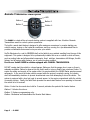
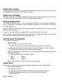
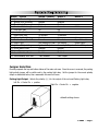
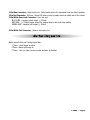
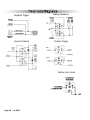
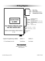
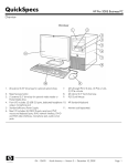
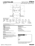
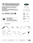
GALAXY G40RS
AUTOMATIC TRANSMISSION ONLY
WITH SEPERATE LOCK/UNLOCK BUTTONS
REMOTE START SYSTEM
PRODUCT MANUAL
Limited Lifetime Warranty
This vehicle remote start system is warranted to the original purchaser, to be free from defects in
material and workmanship. The manufacturer will repair or replace at its option, and free of
charge for the first twelve (12) months, any part that proves defective in material or workmanship
under normal installation, use, and service, provided the product is returned to the manufacturer
freight prepaid. After the first 12 month warranty period there will be a maximum service charge
of $25.00 per calendar year (if required) for repair and/or replacement of any defective parts.
A copy of the original purchase and installation receipt must accompany any products
returned for warranty service. Warranty is limited to defective parts and/or replacement parts
only and excludes any incidental, and consequential damages connected therewith.
WARRANTY OF INSTALLATION LABOR, REMOVAL AND RE-INSTALLATION CHARGES ARE
NOT THE RESPONSIBILITY OF THE MANUFACTURER.
Note: This Warranty is voided if the product was not installed by an
Authorized ScyTek Dealer..
FCC ID: OARRXAM2000
This device complies with Part 15 of FCC Rules.
Operation is subject to the following two conditions:
1) This device may not cause harmful interference.
2) This device must accept any interference received, including interference that may cause
undesired operation
PLEASE NOTE:
Some of the features described in this manual may require additional parts and/or labor, and may not be included
as part of the standard installation of this unit. Additionally, many features of this security system have
selectable options that must be activated or programmed during the system’s installation. These items will be
identified in the following sections. Please discuss these features and any questions you may have regarding the
installation of this product with Your Authorized Dealer.
G 40RS - Page 1
Remote Transmitters
Remote Transmitter Description
LED
Button 1
Button 3
Button 2
Button 4
The G40RS is a state-of-the-art remote starting system is supplied with two 4-button Remote
Transmitters used to control system operations.
The built-in remote start feature is designed to offer maximum convenience by remote starting your
vehicle’s engine, turning on the heater/air conditioner, and then running for a pre-determined time to
provide a comfortable environment once you enter your vehicle.
ScyTek Electronics Inc. and its VENDORS shall not be liable for any accident resulting from the use of this
equipment. This system is designed to be professionally installed into a car or vehicle in which all items,
such as parking brake and all associated components, Hood switches, transmission shift linkage, throttle
linkage, and all engine safety features, are in perfect working condition.
Do not ever Install G40RS in vehicles equipped with MANUAL TRANSMISSION.
DO NOT remote start the vehicle in a closed garage. Make sure that the garage door is open or there is
adequate ventilation. Failure to observe this rule could result in injury or death from poisonous Carbon. To
ensure the safety and security of the system while it is remote started, the G40RS Starter employs several
safeguards. In the event the brake pedal is pressed while the engine is remotely running, the remote
start will immediately shutdown to prevent unauthorized users from attempting to drive the vehicle. The
system is equipped with a hood pin input to prevent access to the engine compartment while the vehicle
is remotely running. Finally, the Valet Mode prevents the remote start feature from operating in the event
the vehicle is to be serviced.
Button 1 Locks the doors and when held for 5 seconds, activates the system’s Car locator feature.
Button 2 Unlocks the doors.
Button 3 Feature programming only.
Button 4 Activates and deactivates the Remote Start feature.
Page 2 - G 40RS
Adding/Replacing Transmitters
To replace lost or stolen transmitters or to add additional transmitters into the system, have all desired
transmitters ready and follow the steps below.
Note: Up to four transmitters can be programmed to operate the system. To erase any previously stored
transmitter codes, be sure to program all 4 transmitter memory locations.
To program transmitter(s):
1. Turn the ignition key On, Off, On, Off, and back On.
· The parking lights will flash 3 times.
2. Press and hold the Override switch for 5 seconds.
· The parking lights will flash 5 times.
· The LED will illuminate.
3. Press Button 1 on the first transmitter.
· The parking lights will flash once.
4. Repeat steps 3 and for each transmitter (up to 4).
5. Turn off the ignition key.
· The parking lights will flash 3 times.
G 40RS - Page 3
System Operation
Remote Locking
To Lock the doors:
1. Turn off the ignition.
2. Press Button 1.
· The doors will lock.
· The parking lights will flash once.
· The LED will turn on, to indicate the doors are locked.
3. 10 seconds after Locking:
· The LED will start blinking.
Remote Unlocking
To Unlock the doors:
Press Button 2.
· The doors will unlock.
· The parking lights will flash twice.
· The LED will turn off .
Remote Starting Automatic Transmission Mode
To Remote Start the System:
1. Be sure the system is not in Valet Mode.
2. Press and hold Button 4
· The parking lights will flash twice.
· The doors will lock (programmable)
· The engine will start and run for the duration of its programmed Run Time.
· The heater or air conditioner will turn on (if turned on prior to exiting the vehicle).
To resume control of the vehicle:
1. Unlock the doors manually or with the Transmitter.
2. Turn on the ignition.
3. Press the Brake Pedal to disengage the remote start.
Visual Car Locator Mode
Use this feature to locate your vehicle in a crowded parking lot. Look for the flashing parking lights
which should be your vehicle!
To activate the Visual Car Locator Mode:
1. Press and hold Button 1 for 3 seconds.
· The parking lights will flash.
· The doors will unlock allowing access to the vehicle.
2. Press Button 2 to turn off Car Finder.
Page 4 - G 40RS
Valet Mode
The Valet Mode temporarily disables the remote start system so the vehicle may be serviced by a mechanic.
The remote transmitters will continue to lock/unlock the doors.
To activate or deactivate the Valet Mode:
1. Turn on the ignition.
2. Press and hold the override switch for 5 seconds.
· The parking lights will flash once and LED will be On to confirm the Valet Mode is on or twice
and LED will turn off to confirm Valet Mode is off.
3. Turn off the ignition.
Shut Down
When the the Remote Start feature is active, any of the following actions will shutdown the engine:
1. Pressing Button 4
· After the engine shuts down the doors will lock (programmable)
2. Pressing the Brake Pedal.
3. Opening the Hood.
4. Remote Start Time-Out (completion of the timed run cycle).
Quick Stop (Automatic Transmission Only)
The Quick Stop Feature allows you to exit the vehicle while keeping the engine running for quick stops.
To leave the vehicle running:
1. Press Button 4 .
2. The parking lights will turn on. Now turn the ignition key off and the vehicle will continue to run.
3. You may now exit the vehicle and lock the doors manually or by using the Remote Transmitter.
To resume control of the vehicle:
1. Unlock the doors manually or with the Transmitter.
2. Turn on the ignition.
3. Press the Brake Pedal to disengage the remote start.
Automatic Start Mode
The Automatic Start Mode allows the vehicle to automatically start the vehicle every one or two hours and
run for the preset Run Time. ( automatic start mode must be selected, feature # 8)
To turn on Auto Starting:
1. Turn Ignition switch Off and wait for 3 seconds.
2. Turn Ignition switch On and Off three times ending with Ignition in Off position
3. Press and release the Valet switch immediatly.
Parking lights will flash indicating that the Auto Start mode has been activated.
To turn off Auto Starting do one of the following:
· Turn ignition On.
· Arm and then Disarm the system
· Alarm or Panic the system
* Automatic Start Mode will stay active for 24 hours only.
G 40RS - Page 5
Ignition Door Locking
For added safety, the Ignition Door Locking feature allows vehicles equipped with power door lock systems
to automatically lock the doors when the ignition is turned on.
Ignition Door Unlocking
For added convenience, this feature automatically unlocks the doors after the ignition key is turned off.
The Ignition Door Unlocking feature may also be completely disabled if desired.
Battery Replacement
Your Remote Transmitter uses (2) 3 volt batteries (type CR2016 ), which will require replacement
in time. Depending on the amount of use, the battery may last up to six months or more before
it needs replacement.
When the battery needs replacing, the system’s operating range will decrease or the transmitter
LED may not be as bright.
In order to change the battery, separate the top and bottom halves of the case.
While replacing the battery make sure that the positive and negative terminals are positioned
correctly, then carefully reassemble the transmitter case.
Entering System Programming
To enter System Programming:
1. Turn on ignition.
2. Within 5 seconds, press the valet switch 5 times.
· The parking lights will flash three (3) times indicating you have entered Programming.
3. Press the valet switch the number times equal to the System Parameter you want to change.
· The parking lights will flash each time the valet switch is pressed.
4. Within 5 seconds, press the transmitter button corresponding to the desired operating mode for
that System Parameter.
· The parking lights will flash to indicate the setting.
1 flash
=
Button 1
2 flashes
=
Button 2
3 flashes
=
Button 3
5. When you are finished, turn off the ignition to save the changes.
Default Reset
Following this procedure will set all System Programming Parameters to factory default settings.
1. Enter System Programming.
2. Press Transmitter Button 3.
· The parking lights will flash 6 times indicating that the reset signal was received.
· All System Programming parameters are now set to factory default settings.
· The Valet Mode is off.
Page 6 -G 40RS
System Programming
Branch Feature
1. Ignition Door Locking
2. Ignition Door Unlocking
3. Door Unlock Pulse
4. Door Lock Pulse Length
5. Lock after Start
6. Lock after Shutdown
7. Engine Run Time
8. Automatic Start Mode
9. Tachless Sense Crank Time
10. Engine Type
11. Ignition 2 Output Program
12. Unlock Before Start
13. Horn Chirp
14. Smart Start Run Monitor
15. Trunk Release/ Horn Out
Button 1 (default)
Enabled
Enabled
Single
1 second
On
On
15 minutes
Disabled
Normal
RPM Mode/RPM Learn
Ignition 2 Output
Disabled
Enabled
Enabled
Trunk Release
Button 2
Disabled
Disabled
Double
3 seconds
Off
Off
25 minutes
2 hours
Extended
Gas Engine
Accessory 2 Output
Enabled
Disabled
Disabled
Horn Output
Button 3
0.1 Sec
1 hour
Super Extended
Diesel Engine
Starter 2 Output
Jumper Selection
Carefully separate the top and bottom halves of the main unit case. Once the cover is removed, the parking
light polarity jumper will be visible next to the parking light relay. Set the jumper for the correct polarity
output as described below, then reassemble the main unit case.
Parking Light Output. Selects the polarity (+/-) for the output of the on-board Parking Light relay.
Left Pin + Center Pin = positive
Right Pin + Center Pin = negative
default setting shown
G 40RS - Page 7
System Installation
8-Pin Main Harness
Pin 1 RED WIRE: Module Power Input (+). Connect to a constant source of +12V
Pin 2 GREEN/WHITE WIRE: Brake Input (+). Connect to the wire that shows +12V when pressing the
brake. The Green/white wire is a safety shutdown wire that must be connected.
Pin 3 BROWN/WHITE: Horn Output (-) 500 mA. Connect to a relay to activate the vehicle’s horn when the
alarm is triggered. This wire may instead be programmed as an ignition 3 relay trigger
Pin 4 WHITE WIRE: Parking Light Output (+/-) relay. Connect the White wire to the circuit that shows
+12V or ground only when the parking lights are on and set the internal parking light relay jumper to
Pin 5
Pin 6
Pin 7
Pin 8
the proper polarity. For parking light circuits exceeding 10 amps, a relay is required. For vehicle’s with
independent left and right parking light circuits, diodes must be installed to keep the circuits separate.
NOTE: Do not connect the WHITE wire to the vehicle’s headlight circuit.
WHITE/BLACK WIRE: Hood Pin Input (-). Connect the to the hood pin switch. The switch must
provide a ground output when switch is opened.
BLUE/ORANGE WIRE: Ground When Running Output (-) 500 mA. Connect to an optional factory
security bypass module if required.
BLACK WIRE: Ground Input (-). The Black wire must connect to a solid chassis ground. Clean away
any paint or dirt to insure the best possible ground.
BLACK/GRAY WIRE: Tach Input. Connect to the vehicle’s tach wire or a fuel injector wire if the
tachless mode does not provide satisfactory operation.
Page 8 - G 40RS
2-Pin Blue Connector: Valet switch port. Mount switch where it is accessible from the driver’s position.
2-Pin Red Connector: LED port. Mount LED where it may be easily seen from either side of the vehicle.
3-Pin White Door Lock Connector: Door lock port.
· BLUE WIRE - negative unlock output (-) 500mA.
· RED WIRE - (+) 100mA trigger output for optional plug-in door lock relay module,
· GREEN WIRE - negative lock output (-) 500mA.
5-Pin White Flat Connector: Antenna connector port.
Starter Diagnostics
Starter doesn’t start and Parking Lights flash:
3 Times - Hood Trigger is active
4 Times - Brake Lights stay On
5 Times - Unit is in Valet (service) mode, and start is disabled.
G 40RS - Page 9
Door Lock Diagrams
Negative Trigger
Adding Actuators
Reverse Polarity
Positive Trigger
blue
green
Positive Horn Honk
Page 10 - G 40RS
Wiring Diagram
Violet
Yellow
Orange
Brown
Red
Red
Red
+12V Battery Input #3
Green/White Brake Input(+)
Brown/White Horn Output (-)500mA
White
Parking Light Output (+/- built-in relay)
White/Black Hood/Trunk Input (-)
Blue/Orange Remote Start output (-) When running
Black
Ground
Black/Gray
Tachometer Input
Control Unit
G-40RS
For Factory Disarm pulse
use the unlock wire
Enable unlock Before Start location
# 12
Starter Output
Ignition 1 Output
Accessory Output
Ignition 2 Output/ACC/Starter2
+12V Battery Input #1 25 Amp.
+12V Battery Input #2 25 Amp.
Green Lock output (-) 500mA.
Empty
Blue
Unlock output (-) 500mA.
OVERIDE SW IN
LED OUT
Antenna
System Programming: Added
15. Trunk Release/ Horn Out
Button 1
button 2
Trunk Release
Horn Output
ScyTek Electronics
11627 Cantara Street
North Hollywood, CA 91605
www.scytek.net
© ScyTek Electronics 2009
G 40RS 7-29-09