1
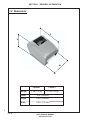
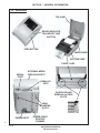
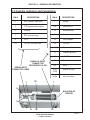
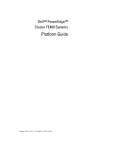
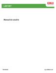
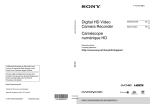
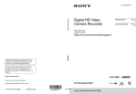
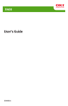
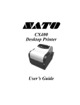
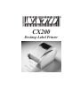
® CX200 Desktop Label Printer Section General Information 1 1-1 Overview The SATO CX Series Printers are compact desktop printers designed especially for bar code labeling and tagging. The CX uses SATO Command Language, making it simple to integrate with any other SATO printer models. Designed for convenience the CX has many advanced features like larger media capacity, user replaceable print head and platen, and a high lift print head carriage that makes it easy to clean and load supplies. This manual covers in detail: CX200DT and CX200TT Direct Thermal and Thermal Transfer Units Features include: • • • • • • • • • 4.1 inch Wide Print Area Label Width From 2 inches to 4.65 inches Up To 3 inches Per Second Print Speed 203 DPI Resolution 512K Flash and 512K RAM Memory 2Mb or 4Mb Expanded Memory 12 Proportional and Mono-spaced Fonts 14 Bar Code Symbologies, Including 2D Parallel and Serial Interfaces Step-by-step maintenance instructions are described in this manual. It is recommended that you become familiar with each section before installing and maintaining your printer. 1 SATO SERVICE MANUAL CX Series Printers Rev B SECTION 1 - GENERAL INFORMATION 1-2 Dimensions D H W Weight CX200DT CX200TT 3.1lb./1.41 kg 3.6 lb./1.63 kg Depth 10 in. (254 mm) Heigth 6.6 in (168 mm) Width 6.9 in. (175 mm) 2 Rev B SATO SERVICE MANUAL CX Series Printers SECTION 1 - GENERAL INFORMATION 1-3 Specifications Model Print Method Resolution Max. Media Width Min Media Width Max. Print Width Max. Print Length Max. Print Speed Installed RAM Installed ROM Communications Max. Media Roll OD Ribbon Label Sensing method Minimum Form Length Text Fonts Graphics Bar Codes CX200DT/CX200TT Direct Thermal/Thermal Transfer 203 dpi 8 dpmm 4.65 inches 118 mm 2.0 inches 51 mm 4.1 inches 104 mm 14 inches 356 mm 3 ips 76 mm/s 512 KB, non-volatile 512 KB, Flash RS232C Serial and Centronics Parallel 5.0 inches 127 mm 460 feet (140m) Wax, Wax/Resin 418 feet (127m) Resin 0.5 inch core, Coated Side Out Eye-Mark, Gap or Notch, Fixed Position 0.375 inches 9.5 mm 12 proportional and monospaced fonts up to 12X expansion PCX and SATO Hex/Binary UPC-A/E, EAN-8/13, UCC/EAN-128, Bookland, Code 39, I 2 of 5, Code 128, Codabar, Plessey, MSI, Code 93, Postnet, PDF417, Maxicode Rotation Text and bar codes can be rotated in four 90o increments Power 20-26 VAC 50/60 Hz or 18-26 VDC 120 VAC 50/60 Hz 230 VAC 50/60 Hz 40 W power supply provided with printer Environmental Operating: Storage: RH: 41o to 104o F (5o to 40o C) - 4o to 122o F (-20o to 50o C) 25 to 85% non-condensing 3 SATO SERVICE MANUAL CX Series Printers Rev B SECTION 1 - GENERAL INFORMATION 1-4 Attributes TOP CASE READY INDICATOR ON-LINE/OFF LINE BUTTON FEED BUTTON PAPER GUIDE BOTTOM CASE FRONT CASE SERIAL PORT EXTERNAL MEDIA FEED KNOCKOUT PARALLEL PORT PLATEN ROLLER REMOVAL ACCESS SLOTS WALL MOUNTING SLOTS POWER INPUT 4 POWER CABLE ROUTING CHANNEL Rev B SATO SERVICE MANUAL CX Series Printers SECTION 1 - GENERAL INFORMATION 1-4 Attributes PAPER GUIDE (SHOWN WITH LABELS) PAPER GUIDE (SHOWN WITHOUT LABELS) RELEASE LEVERS FOR PRINT HEAD/RIBBON MECHANISM 5 SATO SERVICE MANUAL CX Series Printers Rev B SECTION 1 - GENERAL INFORMATION 1-5 Controls, Indicators and Connections The following table summarizes the functions of the various printer controls, indicators, and connections. DEVICE NAME FEED button PRIMARY FUNCTION Advances print media READY indicator Shows print status USE PRESS - to advance media PRESS while pressing READY indicator-to print test label PRESS to pause printing during batch mode operation GREEN - Printer ready for data OFF - Printer busy, or Off-Line RED - Printer needs attention ON-OFF line Places printer in OnLine or Off-Line mode PRESS to switch to/from Off-Line or to reset the printer Power input Connects to power supply Connect to power supply provided with printer Serial port Data input DB9 female connector for connection to host controller, RS232 interface Parallel port Data input Centronics compatible connector for connection to host controller Print head release Unlocks print head Push both releases toward rear of printer to release print head Media cover Protects print media mechanism Lift to open Push outward at hinge to remove 6 Rev B SATO SERVICE MANUAL CX Series Printers SECTION 1 - GENERAL INFORMATION 1-5 Controls, Indicators and Connections PIN # DESCRIPTION PIN # 2 RXD (printer data input) 1 Strobe 3 TXD (printer data output) 2-9 Data bits 0-7 5 Ground 10 Acknowledge 7 RTS (printer busy) 11 Busy 8 CTS 12 Out of paper +5 VDC, 200 mA max 13 +5 VDC 14-15 No connection 17 Chassis ground 18 +5 VDC 31 Reset 32 Error 1,9 PARALLEL INPUT CONNECTOR CENTRONICS 36 PIN SERIAL INPUT CONNECTOR DB9S 18 1 DESCRIPTION 16,33 19-30 Signal Ground 34-36 No connection 1 5 BACK END OF PRINTER 9 6 36 19 SATO SERVICE MANUAL CX Series Printers 7 Rev B SECTION 1 - GENERAL INFORMATION 1-5 Controls, Indicators and Connections Printer Power Connection 1. Plug the output of the AC power supply provided with the printer into the connector on the underside of the printer. 2. Plug the supply into an AC outlet having the correct voltage. Important! The required AC voltage is marked on the power supply. Confirm that your AC voltage matches the power supply requirements. Do not use any power supply other then the one provided with the printer. Note: CX200 printers consume very little power when idle so are not equipped with a power switch. Press the READY indicator/ON-OFF (a combined control) to reset the printer and switch from OFF-Line to On-Line mode. POWER SUPPLY UNDERSIDE OF PRINTER POWER INPUT READY INDICATOR ON-LINE/OFF LINE BUTTON AC OUTLET FEED BUTTON 8 Rev B SATO SERVICE MANUAL CX Series Printers SECTION 1 - GENERAL INFORMATION 1-5 Controls, Indicators and Connections Connecting the Interface Cable AVAILABLE DB9S SERIAL PORT PARALLEL PORT CONNECT THIS END OF THE CENTRONICS 36 PIN CABLE TO THE PARALLEL PORT ON THE PRINTER CONNECT THIS END OF THE PARALLEL CABLE TO THE PORT ON THE COMPUTER 9 SATO SERVICE MANUAL CX Series Printers Rev B SECTION 1 - GENERAL INFORMATION 1-6 Printer Setup Loading Labels or Tags ALSO REFER TO THE ACCOMPANYING ILLUSTRATIONS (NEXT PAGE) 1. Lift open the top case. 2. Press the two print head releases toward the rear of the printer to unlock the print head. The print head will pop up slightly. Lift it up until it is fully raised. 3. Remove print media (if any) or empty core from the printer. 4. Unwrap the new media and unwind a few labels from the roll. Labels must be wound face-in for best results. 5. Slide the paper guide all the way to the right. 6. Place media roll in the tray so that the media unwinds from the bottom of the roll toward the front of the printer. The label imaging surface must face up as it passes under the print head. 7. Lift the print head and slip the free end of the media under the print head. 8. Adjust the paper guide until the media is snug between the paper guide and the left side of the paper tray. 9. Lower the print head and press it down firmly until it locks closed on both sides. 10. Close the top case. 11. Wait until the Ready Indicator glows green, then press the FEED button to feed a label or to resume printing. 12. If the printer feeds out 7 inches of label and stops and the indicator glows red, recalibrate for the media installed. See calibration. 10 Rev B SATO SERVICE MANUAL CX Series Printers SECTION 1 - GENERAL INFORMATION 1-6 Printer Setup Loading Labels or Tags PRESS BACK THE RELEASES TO UNLOCK PAPER GUIDE MEDIA ROLL LIFT PRINT HEAD AND SLIDE UNDER MEDIA READY INDICATOR FEED BUTTON 11 SATO SERVICE MANUAL CX Series Printers Rev B SECTION 1 - GENERAL INFORMATION 1-6 Printer Setup Loading Ribbon The CX200TT Thermal Transfer Printer transfers ink from a ribbon to the label to produce an image. Ribbon is N/A for CX200DT ALSO REFER TO THE ACCOMPANYING ILLUSTRATIONS 1. Lift open the top cover. 2. Press the two print head releases toward the rear of the printer to unlock the printhead. The print head will pop up slightly. Lift it up until it is fully raised. 3. Unwrap the new ribbon and unwind about 4" from the roll. The end of the ribbon is attached to a take-up core. 4. Observe the notches on both ends of the supply core and the take-up core. These notches must fit on the corresponding nibs on both the supply and take-up spindles. 5. Roll several turns of ribbon on the take-up core, winding to the underside as shown. The dull (coated) side of the ribbon must be on the outside of the take-up roll. 6. Place the take-up core (ribbon unrolling from the top side) into the left take-up spindle, lining up the notches with the spindle nibs. The take-up spindles are the take-up spindles. 7. Pull out the spring loaded knob on the right take-up spindle and place the right end of the take-up core into the right spindle, lining up the notches with the spindle nibs. 8. Pull the ribbon down and over the print head and insert the supply core onto the left supply spindle, making sure the notches in the core fit over the nibs. 9. Pull out the spring loaded knob on the right supply spindle and place the right end of the supply core into the right spindle, lining up the notches with the spindle nibs. Note: Make sure the (coated) dull side of the ribbon is to the outside where it will be in contact with the label media. 12 Rev B SATO SERVICE MANUAL CX Series Printers SECTION 1 - GENERAL INFORMATION 1-6 Printer Setup Loading Ribbon (Continued) 10. Turn the take-up knob to pull the ribbon over the print head without any slack. Check to make sure there are no ribbon wrinkles. 11. Lower the print head and press it down firmly until it locks closed on both sides. 12. Close the top case. 13. Wait until the Ready Indicator glows green and press the FEED button to feed a label or to resume printing. 14. If the printer feeds out 7 inches of label and stops, and the indicator glows red, recalibrate for the media installed. See calibration. PRESS BACK THE RELEASES TO UNLOCK DIRECT THERMAL UNIT SHOWN (NO RIBBON) SPINDLE NOTCHES BOTH ENDS UNWIND ABOUT 4" SPINDLE NOTCHES BOTH ENDS ROLL SEVERAL TURNS ON THE TAKE-UP CORE 13 SATO SERVICE MANUAL CX Series Printers Rev B SECTION 1 - GENERAL INFORMATION 1-6 Printer Setup Loading Ribbon (Continued) PLACE TAKE-UP CORE INTO LEFT TAKE-UP SPINDLE SUPPLY KNOB SPRING LOADED RIBBON TAKE-UP KNOB TAKE-UP CORE PRINT HEAD SUPPLY ROLL PULL THE RIBBON OVER THE PRINT HEAD TAKE-UP KNOB 14 Rev B SATO SERVICE MANUAL CX Series Printers SECTION 1 - GENERAL INFORMATION 1-6 Printer Setup Loading Ribbon (Continued) TURN RIBBON TAKE-UP KNOB CLOCKWISE TO ELIMINATE RIBBON SLACK LOWER THE PRINT HEAD AND PRESS DOWN FIRMLY ON BOTH HEAD LATCHES TO LOCK THE PRINT HEAD IN POSITION Selecting the Label Sensor Type CX200 printers support Eye-Mark, gap, or notch label sensing. The printer must be set for the proper sensing method. If you are using label printing software, it should provide a means to set up these parameters. See your software documentation for details. If you are writing your own software or controlling the printer using direct commands, you must use printer commands to set up the print mode and sensing method. Refer to the programming manual. 15 SATO SERVICE MANUAL CX Series Printers Rev B 1-7 Printer Test and Calibration Preparation for Test These procedures run a complete set of performance tests. If the printer fails a test, troubleshoot as required, then rerun all tests. Inspect the printer for physical damage before testing or calibrating it. Inspect for: Cuts or gouges in the rubber drive roller Dust buildup or other obstructions of the label sensor or sensor LED Adhesive buildup or scratches on the print head Adhesive buildup or other obstructions in the paper path Any other physical damage that might affect printer alignment Correct any problems found before beginning the printer calibration using the calibration software. NOTE: The calibration software is DOS-based and can be run directly from the diskette or installed on your hard drive. You must run the software from the DOS prompt. If using Windows 95, reboot your computer in MS-DOS mode. Do not try to run the software in a window. Installing the software to your hard drive: 1. At the DOS prompt, insert the calibration disk in your computer's 3-1/2 disk drive and access the drive. 2. At the prompt, type dir and press the Enter key. 3. Copy the file CX200.exe to your hard drive. 4. Type CX200.exe to view the opening screen. Refer to the following pages to continue with the program. 16 Rev B SATO SERVICE MANUAL CX Series Printers 1-7 Printer Test and Calibration Preparation for Test Running the software from your 3-1/2 drive 1. At the DOS prompt, insert the calibration disk in your computer's 3-1/2 disk drive and access the drive. 2. At the prompt, type CX200.exe and press the Enter key. The opening screen will appear. Review the menu and make your selection. At the prompt, type 1, 2, 3, 4, or to exit the program type 0. Description of Test Menu 1. Print Head / Status Print - Prints head pattern status. Refer to illustration on page 26 2. Change RS232 Settings - Sets the RS232 settings through the LPT1 port 3. Set Top of Form - Positions the label towards or away from the sensor. 4. Calibrate Printer - Calibrates printer to current label and/or ribbon installed in the machine. 17 SATO SERVICE MANUAL CX Series Printers Rev B 1-7 Printer Test and Calibration Print Head / Status Print Access the software 1. Enter 1 at the prompt. 1 2. As the sequential screens appear, respond to the prompts. Refer to page 26 for an example of a test label. 18 Rev B SATO SERVICE MANUAL CX Series Printers 1-7 Printer Test and Calibration Change RS232 Settings Access the software 1. Enter 2 at the prompt. 2 2. As the sequential screens appear, respond to the prompts. 19 SATO SERVICE MANUAL CX Series Printers Rev B 1-7 Printer Test and Calibration Change RS232 Settings (Continued) Continue to respond to the prompts or enter a choice on the sequential screens. Run a test label to verify that the new RS232 parameters were entered correctly. Select 1. Print Head / Status Print from the main menu. 20 Rev B SATO SERVICE MANUAL CX Series Printers 1-7 Printer Test and Calibration Set Top of Form (Pitch Offset) Access the software 1. Enter 3 at the prompt. 3 2. As the sequential screens appear, respond to the prompts. 21 SATO SERVICE MANUAL CX Series Printers Rev B 1-7 Printer Test and Calibration Set Top of Form (Pitch Offset), Continued Continue to respond to the prompts or enter a choice on the sequential screens. After the Offset command is sent to the printer, two labels are printed with a single horizontal line at a V=000 print position. The first line will be printed at the old offset position and the second at the new position. Compare them to make sure the desired change was effected. The new setting will be printed on the last line of the first label. 22 Rev B SATO SERVICE MANUAL CX Series Printers 1-7 Printer Test and Calibration Calibrate Printer Access the software 1. Enter 4 at the prompt. 4 2. As the sequential screens appear, respond to the prompts. 23 SATO SERVICE MANUAL CX Series Printers Rev B 1-7 Printer Test and Calibration Calibrate Printer (Continued) Continue to respond to the prompts or enter a choice on the sequential screens. Sequence of events when the Calibration Program is run: 1. The Indicator goes out. 2. The motor slowly feeds a label until a gap or mark is found. 3. The indicator glows green and prints one label with the message "calibration successful". 4. If the label does not print and the indicator glows red, repeat the calibration procedure. 24 Rev B SATO SERVICE MANUAL CX Series Printers 1-8 Basic Operations Printing and Reading a Self-test Label Printing a self-test label checks the printer's overall operability. To run a selftest, confirm that the printer is loaded and connected to AC power and no print jobs are in process then: 1. Press and hold in the READY indicator. 2. Press and release the FEED button. 3. The printer should begin printing a self-test label. Release the READY indicator after printing starts. 4. After the self-test label finishes printing, press the READY indicator to reset the printer and restore normal operation. Important! The printer will be in hex dump mode after printing the self-test label. It cannot print normal labels in hex dump mode, instead it prints the hex value for each character received. The printer will return to normal operation after you reset it as described in step 4 above. READY INDICATOR ON-LINE/OFF LINE BUTTON FEED BUTTON 25 SATO SERVICE MANUAL CX Series Printers Rev B 1-8 Basic Operations Printing and Reading a Self-test Label Firmware Revision Serial Number RS232 Setting Current Printer Heat Setting Total Number of Inches Printed Print Speed Current Calibration Setting Print Mode (DT= Direct Thermal ) (TT= Thermal Transfer) Label Forward/Backfeed Protocol Codes (Factory Use Only) Expanded Memory Installed Pitch Offset Hex Dump Mode Hex Dump Code EXAMPLE: SELF TEST LABEL When sending data in normal operation and nothing prints, put the printer in the Hex mode and try resending the data. The printer should print out the hex characters corresponding to the data received. If nothing prints, check cabling and media. If you get a hex dump, compare it to the command stream you are sending. If it is the same, the command sent could be wrong. Refer to the Programming Guide for information on programming the printer and the correct use of the printer commands. 26 Rev B SATO SERVICE MANUAL CX Series Printers 1-8 Basic Operations Feeding Blank Labels To feed a label, press and release the FEED button with the printer off-line. Press and hold in the FEED button to feed multiple labels. Note: The printer has a last label repeat feature. If this feature is enabled, pressing the Feed key with the printer on-line (READY indicator green), will repeat print any label in the buffer. If the printer is placed in the off-line mode, it automatically clears any label that is in the buffer. Label Reprint The printer has a last label repeat feature. If this feature is enabled and the last label printed has not been cleared from the print buffer by pressing the READY indicator to take the printer Off-Line, then pressing the FEED button will cause the last printed label to be reprinted. Sending Data to the Printer To print labels using data sent from a host computer or terminal: 1. Connect the host and printer serial or parallel ports together using a correctly wired interface cable, (the parallel cable supplied with the printer, or a null modem RS232 cable.) 2. If you are using the serial port, confirm that the host and printer are using the same communications parameters. The current parameters are printed out on the "comm:" line on the test label. 3. Confirm that the READY indicator is glowing green. 4. Send your data to the printer. Printer Ready/Standby/Reset Control CX200 printers do not have a power switch, but you can effectively "turn off" the printer by pressing the READY indicator. This resets the printer's microprocessor and places the printer in standby. Resetting the microprocessor will: Stop any printing. Delete the label format in process from memory. Reset the printer communication ports. Return all printer parameters to their default (first power-on) state. 27 SATO SERVICE MANUAL CX Series Printers Rev B 1-8 Basic Operations Printer Ready/Standby/Reset Control Pressing the READY indicator a second time will return the printer to On-Line mode (its default condition). Resetting the printer in this manner does not harm it in any way, nor does it affect the contents of nonvolatile RAM or remove any stored objects. The effect is the same as if you had unplugged and reconnected the printer power supply. Printing Labels To print labels, the host computer sends commands to the printer via the serial or parallel communications port. If you are using the Label Wizard CX label printing software supplied on the CD-ROM (included with the printer), the computer and software control the entire printing process. You only need to set up the SATO generic printer, start your label printing program, and follow its instructions. If you are using another vendor's software package, contact the software supplier or manufacturer if you encounter difficulties. A complete Reference Manual for the Label Wizard CX label design and printing software is included on the CD-ROM. If you want to print labels from another Windows application, the CX200 Windows Printer Driver must be installed. It is found on the CD-ROM and must be loaded using the standard Windows printer installation instructions. Controlling the Printer Using Direct Commands You can also produce labels by sending commands directly to the printer. Simple ASCII commands control the printer. You can write command files using any text editor program that can output ASCII text (including the control codes). Since printer programming is potentially complex, programming information is not provided here. A printer command reference and basic programming procedures are provided on the CD-ROM packed with the printer. The file CXManual.pdf on the disk is in Adobe Acrobat format, readable using the Adobe Acrobat Reader provided in the AcroRead directory on the CD-ROM or can be downloaded free of charge from http://www.adobe.com. This program will allow you to search the contents of the manual and /or print a hard copy. If you need programming information and are not using Windows (or cannot read the CXManual.pdf file for any other reason), contact our Technical Support Services Organization for assistance. 28 Rev B SATO SERVICE MANUAL CX Series Printers Section 2 Maintenance 2-1 Cleaning SATO America printers need very little maintenance other than occasional cleaning. Clean the printer body as required, using a soft cloth moistened with a mild detergent cleaner. Caution! Do not use abrasives on the printer body. The finish may be ruined. Clean the print head if it appears dirty or if print quality is poor. To clean the print head: ALSO REFER TO THE ACCOMPANYING ILLUSTRATIONS 1. Lift open the top case. 2. Press the two print head releases toward the rear of the printer to unlock the print head. The print head will pop up slightly. Lift it up until it is fully raised and latched in the up position. 3. Using a SATO Direct Thermal Print Head Cleaning Sheet or a soft coth moistened with 99% pure isopropyl or denatured alcohol, clean all dirt and label residue from the print head, paying particular attention to the "burn line" (the thin black line near the front edge of the print head). Caution! Do not clean the print head or platen roller using abrasive or metallic objects or ammonia-based cleaners or other harsh chemicals. These practices can cause serious damage and will void the warranty. 4. Wipe the platen roller with a cleaning cloth. To reach all portions of the platen roller, press the FEED button. The roller will rotate 1/4 turn each time you press the FEED button. Caution! Keep all objects clear of the platen roller when you press the FEED button. SATO SERVICE MANUAL CX Series Printers 29 Rev B 2-1 Cleaning 5. Confirm that the label sensor is unobstructed. Clean away any obstruction with a soft brush if necessary. 6. Resume the media loading procedure, or if there is already media in the printer, lower and lock the print head. 7. Resume normal operation. PRESS BACK THE RELEASES TO UNLOCK RAISE THE PRINT HEAD CLEAN THE PRINTHEAD NOTE THE "BURN LINE" 30 Rev B SATO SERVICE MANUAL CX Series Printers 2-1 Cleaning CLEAN THE PLATEN ROLLER LABEL FEED DIRECTION PLATEN ROLLER LABEL SENSOR MUST REMAIN UNOBSTRUCTED 31 SATO SERVICE MANUAL CX Series Printers Rev B 32 Rev SATO SERVICE MANUAL CX Series Printers Section Parts Replacement 3 3-1 Preparing the Printer for Service Caution! Some of the components in the printer are extremely sensitive to static discharge damage. When servicing the printer, observe good static prevention practices. Place the printer on a grounded, conductive work surface. Ground yourself to the work surface through a 1 megohm series resistor, using a conductive wrist strap or other suitable device. Ground any tools that will contact the equipment (holding the conductive portion of the tools can provide a suitable ground). Keep replacement components in their protective packing until they are needed, and do not handle unnecessrily. After repairs are completed: After making the necessary repairs, reconnect the printer power supply and reinstall the print media. Confirm that the printer status LED glows green, and that the printer will feed a label when you press the FEED button. 33 SATO SERVICE MANUAL CX Series Printers Rev B 3-2 Replaceable Parts The following is a list of replaceable parts covered in these instructions. SECTION DESCRIPTION KIT PART NUMBER 3-3 TOP CASE 14SC00116 3-4 BOTTOM CASE 14SC00114 3-4 FRONT CASE 14SC00117 3-5 PLATEN 14SC00111 3-6 PRINT HEAD 14S C 00101 3-7 PCBA MODULE 512K 14SC00110 3-8 PCA BASE BOARD 14S C 00120 3-9 MOTOR 14S C 00105 3-10 SWITCH 14S C 00104 3-11 GEAR CLUSTER 14S C 00109 Refer to the Section Number for method of replacement 34 Rev B SATO SERVICE MANUAL CX Series Printers 3-2 Replaceable Parts TOP CASE BOTTOM CASE PRINT HEAD FRONT CASE PLATEN PLATEN GEAR CLUSTER PCBA MODULE MOTOR SWITCH PCA BASE BOARD 35 SATO SERVICE MANUAL CX Series Printers Rev B 3-2 Replaceable Parts Location PRINT HEAD SWITCH GEAR CLUSTER PLATEN TOP CASE PRINT HEAD BOTTOM CASE PCBA MODULE MOTOR FRONT CASE 36 Rev B SATO SERVICE MANUAL CX Series Printers PCA BASE BOARD 3-3 Top Case Removal/Replacement REFER TO THE ILLUSTRATION 1. Lift open the top case 2. Press the two sides of the top case outward to unlatch from the bottom case, and remove. PRESS OUTWARD PRESS OUTWARD 37 SATO SERVICE MANUAL CX Series Printers Rev B 3-4 Chassis, Including the Front Case Removal/Replacement The chassis must be removed to access and remove other components that are fastened to the chassis body. The front case is set in slots in the bottom case and both are removed from the chassis as a unit. The chassis is held in the printer case by two tabs, which can reached through two access slots in the bottom of the printer. To simplify the process of removing the chassis from the printer, follow these instructions closely. REFER TO THE ACCOMPANYING ILLUSTRATIONS To remove the chassis: Insert a flat-bladed screwdriver into each of the two chassis release slots between the tabs and case and push the screwdriver in the direction shown. For the right side slot, insert the screwdriver and push toward the front of the printer. For the left side slot, insert the screwdriver and push toward the rear of the printer while pulling the chassis away from the printer case. The front case will come out with the chassis. Lift the front case from the chassis. INSERT SCREWDRIVER INTO EACH SLOT, PUSH UP ON THE RIGHT SIDE, PUSH DOWN ON THE LEFT SIDE PUSH UP TO THE FRONT CASE TAB INSERT SCREWDRIVER BETWEEN TAB AND CASE RIGHT SIDE TAB PUSH DOWN TO THE REAR LEFT SIDE TAB 38 Rev B SATO SERVICE MANUAL CX Series Printers 3-4 Chassis, Including Front Case Removal/Replacement (Continued) FRONT CASE CHASSIS FRONT CASE (BOTH SIDES) LEDGE SLOT BOTTOM CASE CHASSIS WIRE TABS ON THE CENTRONICS CONNECTOR MUST BE IN A FORWARD POSITION WHEN INSERTED THROUGH THE OPENING IN THE CASE SLIDE THE EDGES ON THE FRONT CASE INTO THE RECESSES ON THE BOTTOM CASE To replace the chassis and front case: 1. While lowering the chassis into the bottom case, guide the communication port connectors through the slot in the bottom rear of the bottom case. Do not press the chassis all the way down yet; just lower it gently into position. 2. Position the front case on the front of the printer chassis. The small ledges at the sides of the front case serrated edges fit into slots at the left and right sides of the chassis. 3. Carefully guide the Centronics connector on the chassis into the opening on the case so that the wire tabs are in a forward position when inserted through the case. Gently press the printer chassis all the way down into the bottom case while guiding the side edges on the front case into the recesses of the bottom case. SATO SERVICE MANUAL CX Series Printers Rev B 39 3-5 Platen Removal/Replacement REFER TO THE ACCOMPANYING ILLUSTRATIONS Platen removal: 1. Raise the top case. 2. Press the two print head release latches back to release the print head, then lift the print head until it is fully raised and latched in the open position. 3. Insert a flat-bladed screwdriver into the right slot on the front case. Press down on the screwdriver to force the platen up on the right side. This will release the right end of the platen. 4. Repeat steps 2 and 3 using the slot on the left side of the front case. This will release the left end of the platen. 5. Lift the platen clear of the chassis. INSERT FLAT BLADED SCREWDRIVER INTO SLOTS PRESS BACK THE RELEASES TO UNLOCK Platen installation: Lower the platen into the printer chassis and press down until it snaps into place. 40 Rev B SATO SERVICE MANUAL CX Series Printers 3-6 Print Head Removal/Replacement REFER TO THE ACCOMPANYING ILLUSTRATIONS Print head removal: 1. Raise the top case. 2. Press the two print head release latches back to release the print head, then lift the print head until it is fully raised and latched in the open position. 3. Press the print head down with your thumbs (towards the printer chassis) and slide the front edges away from the slots on the printer frame. 4. Pull the print head away from the printer frame and rotate towards you so that the springs are facing your direction. 5. Unplug the print head ground lead from its push-on connector on the print head. Unplug the sensor LED connector. NOTE: The sensor LED is polarity-sensitive; observe the orientation of the LED connector when disconnecting and reconnecting it. The red lead should be closest to the print head. 6. Unplug the print head connector. PRESS PRINT HEAD DOWN AND SLIDE FRONT EDGES AWAY FROM THE SLOTS PRINT HEAD PRESS BACK THE RELEASES TO UNLOCK 41 SATO SERVICE MANUAL CX Series Printers Rev B 3-6 Print head Removal/Replacement SLIDE FRONT EDGES AWAY FROM SLOTS PULL PRINT HEAD AWAY FROM FRAME UNPLUG PRINT HEAD CONNECTOR UNPLUG LED CONNECTOR Print head installation: Reverse the above steps to install the print head. 42 Rev B SATO SERVICE MANUAL CX Series Printers UNPLUG GROUND LEAD FROM PUSH-ON CONNECTOR 3-7 PCBA Module Removal/Replacement REFER TO THE ACCOMPANYING ILLUSTRATIONS Module removal: 1. Remove the printer chassis according to the instructions in Section 3-4. 2. Remove the module from the PCBA base board by pressing outward on the two spring clips at the left and right ends of the module . 3. Lift the module up and out to remove. PRESS THE TWO SPRING CLIPS OUTWARD PRESS THE TWO SPRING CLIPS OUTWARD PCBA MODULE PCBA BASE BOARD Module replacement: 1. Press the module firmly into its connector on the PCBA base board. 2. Press the top edge of the module in toward the printer body until the connector spring clips engage. 3. Reinstall the chassis in the case according to the directions in Section 3-4. 43 SATO SERVICE MANUAL CX Series Printers Rev B 3-8 PCA Base Board Removal/Replacement REFER TO THE ACCOMPANYING ILLUSTRATIONS PCA board removal: 1. Remove the printer chassis according to the instructions in Section 3-4. 2. Remove the module from the main PCA board according to the instructions in Section 3-7. 3. Remove the two Phillips-head screws holding the main PCA board in place. 4. Lift the PCA board gently, then unplug the feed switch connector at J13. 5. Turn the PCA board over and unplug all other connectors. BACK OF THE PCA BOARD REMOVE (2) SCREWS UNPLUG CONNECTOR AT J13 UNPLUG ALL CONNECTORS PCA board installation: 44 Reverse the above steps to install the main PCA board. Rev B SATO SERVICE MANUAL CX Series Printers 3-9 Motor Removal/Replacement REFER TO THE ACCOMPANYING ILLUSTRATIONS Motor removal: 1. Remove the printer chassis according to the instructions in Section 3-4. 2. Remove the two Phillips-head screws holding the PCA base board in place. 3. Lift the PCA base board gently, then unplug the feed switch connector at J13 4. Unplug the motor wiring at connector J10 5. Remove the Phillips-head screw holding the motor in place. 6. Turn the motor body until the motor flanges clear the printer chassis, then remove the motor. UNPLUG THE CONNECTOR AT J10 REMOVE PHILLIPSHEAD SCREW AND LIFT THE MOTOR Motor installation: Reverse the above steps to install the motor. 45 SATO SERVICE MANUAL CX Series Printers Rev B 3-10 Head Open Switch Removal/Replacement REFER TO THE ACCOMPANYING ILLUSTRATIONS Switch removal: 1. Remove the printer chassis according to the instructions in Section 3-4. 2. Insert a flat-bladed screwdriver under the switch body and gently pry it up to detach from the chassis protrusions. 3. Unplug the two connectors. UNPLUG CONNECTORS GENTLY PRY THE SWITCH BODY WITH A FLAT-BLADED SCREWDRIVER Switch installation: Reverse the above steps to install the switch. 46 Rev B SATO SERVICE MANUAL CX Series Printers SCREWDRIVER BLADE 3-11 Cluster Gear Removal/Replacement (Continued) REFER TO THE ACCOMPANYING ILLUSTRATIONS Cluster gear removal: 1. Remove the chassis according to the instructions in Section 3-4. 2. Remove the platen according to the instructions in Section 3-5. 3. Turn the chassis so that its right side rests on the work surface. The drive gears should be facing you. If you are servicing a direct thermal printer, there will be only two gears, the motor drive gear (brass) and the cluster gear (black plastic). NOTE: The motor drive gear is permanently attached to the drive motor; do not attempt to remove it. 4. Pull the damaged gear or gears off of the printer chassis. CLUSTER GEAR MOTOR DRIVE GEAR (DO NOT REMOVE) Cluster gear installation: Reverse the above steps to install the gear(s). 47 SATO SERVICE MANUAL CX Series Printers Rev B 48 Rev B SATO SERVICE MANUAL CX Series Printers Section 4 Troubleshooting 4-1 Preliminary Tests SATO printers are very reliable, so printing problems are unlikely. If you do think you have a printer problem, proceed as follows: REFER TO THE ILLUSTRATIONS ELSEWHERE IN THIS MANUAL 1. Confirm that the printer has the right media installed, and that it is loaded correctly as described in this manual. 2. Confirm that the printer is connected to its power supply and the supply is plugged into an AC outlet having the proper voltage. Measure the voltage at the output of the power supply. It should be 24V +/- 10%. 3. Open the print head and inspect the media path. Remove any obstructions, and clean the print head and drive roller according to the instructions in this manual. 4. Press down firmly on both print head latches to confirm that they are closed. 5. Confirm that the printer READY indicator glows green. 6. Print a self-test label as described in this manual. (Page 26) 7. Press FEED to confirm that the printer will feed a label. 8. Review the common problems described in this section. Note: The information here assumes you are using label printing software. If you are programming the printer, please review the information in the CXProg.pdf file located on the CD-ROM. 49 SATO SERVICE MANUAL CX Series Printers Rev B 4-2 Common Problems and Their Solutions READY light is not lit 1. Press the READY light. 2. Double-check the AC source and the power supply connections. 3. Disconnect the cable between the printer and the host, then reset the printer as described in this manual. 4. If the READY light glows green with the host disconnected, suspect a host computer or cabling problem. READY light glows red 1. Press the FEED switch to assure that the printer is not paused in batch mode printing. 2. Confirm that the print media is not exhausted. 3. Confirm that the print head is securely latched down on both sides. 4. If you have printed many labels, the printer may have overheated. Normal operation will resume after the printer has cooled sufficiently. Self-test label will not print 1. Confirm that you have loaded direct thermal media if the unit is a CX200DT. 2. Disconnect the cable between the printer and the host computer. Reset the printer as described in this manual, then try to print a self-test label again. 3. Confirm that the coated (dull) side of the ribbon (CX200TT) is on the outside where it will be in contact with the label media. Labels will not feed 50 1. Confirm that the print media is loaded correctly. 2. Reset the printer as described in this manual. Confirm that the printer LED indicator glows green. Press the FEED button. 3. If the printer still does not feed, disconnect the communications cable and repeat step 2. If the printer feeds with the cable disconnected, suspect a problem with the host computer or cable. Rev B SATO SERVICE MANUAL CX Series Printers 4-2 Common Problems and Their Solutions (Continued) Host stops responding or displays "printer not ready" message 1. Review your software setup, following the instructions provided with the software. 2. Confirm that the host-to-printer communication cable is connected and undamaged. If using the serial port, confirm that you are using a null modem cable or adapter. 3. If using the serial port, confirm that the host and printer are both using the same serial port parameters. The self-test label shows the current printer serial port parameters. 4. If using a communications switch between the host and printer, remove the switch and connect the printer directly to the host. 5. Reset the printer as described in this manual, reset the host computer and software, and try printing again. Host stops responding or displays "printer not ready" message 1. Review your software setup, following the instructions provided with the software. 2. Confirm that the host-to-printer communication cable is connected and undamaged. If using the serial port, confirm that you are using a null modem cable or adapter. Poor print quality 1. Confirm that the print media is properly loaded, and there is no side-toside motion of the paper as it feeds through the printer. 2. Check your software's print darkness and print speed settings. These settings may need adjustment for optimum results. 3. Try different print media. Old or inferior quality media will degrade print quality. 51 SATO SERVICE MANUAL CX Series Printers Rev B 4-2 Common Problems and Their Solutions (Continued) Printer feeds too many labels 1. Verify correct label loading (Eye-Mark bars, if any facing down). 2. Print a test label to confirm that the printer is set for the proper sensor type. If the sensor type does not match the currently loaded print media, either change the media or change the sensor setting using the SELECT SENSOR command. 3. If using Eye-Mark indexing, confirm that the label stock has good black bars at least 1/8" wide and that the bars are positioned to pass over the reflective optical detector. The reflectance of the black bars should not exceed 12% maximum at a wave length of 850 nanometers. 4. If using gap indexing, confirm that the label stock has a minimum 1/8" gap between each label. 5. Confirm that the sensor and LED light source are both unobstructed. 6. Recalibrate the printer according to the instructions in this manual. If none of the above steps correct the problem, the label sensor may be defective. Printed bar codes won't scan 52 1. Confirm that the commands you are sending to the printer will print a bar code that conforms to a standard bar code symbology. Confirm that the characters you are attempting to encode are legitimate characters for the selected bar code type. 2. Confirm that the scanner is set up to scan the bar code type you are printing. 3. Confirm that the print head is clean. Clean it if required. Check the overall print quality. If the print quality is poor, proceed as for "Poor print quality." 4. If you are using direct thermal printing and an infrared scanner, confirm that your direct thermal paper is infrared scannable as follows: A. Print a bar code. B. Photocopy the printed bar code on a plain-paper copier. C. Scan the photocopy. If the copy scans properly and the original does not, your direct thermal label stock is not infrared scannable. D. Inspect and confirm that the print head is not damaged. E. Run a Self Test label and examine the head pattern. Rev B SATO SERVICE MANUAL CX Series Printers 4-2 Common Problems and Their Solutions (Continued) Ribbon wrinkles Occasional ribbon wrinkling may not indicate a printer problem, but if wrinkling occurs often, check the following: 1. Raise the print head. 2. Confirm that the ribbon cores are correctly seated on the ribbon spindles. 3. Turn the ribbon take-up knob clockwise and confirm that the ribbon runs smoothly. If the ribbon binds, remove the ribbon cores and examine the ribbon spools, spool springs, and gears for possible damage. Remove any label debris or other obstructions. 4. Close the print head. Confirm that the ribbon take-up gears engage properly. 5. Resume normal operation If the problem persists, try replacing the ribbon. A damaged or inferior quality ribbon may wrinkle easily, especially with high heat settings. Printer skips labels while printing 1. Confirm that the printer will feed one label at a time using the FEED switch. If the printer feeds more than one label when you press the feed switch, see "Printer feeds too many labels" for troubleshooting information. 2. If using eye-mark indexing, confirm that there are black bars printed on the back of every label and that the index bars are positioned such that they pass over the sensor. If using gap sensing, confirm that there is a uniform gap (at least 1/8" wide) between each label. 3. Print a test label to confirm that you have selected the proper sensing method for your label media. 4. Calibrate the label sensor according to the procedure in this manual. 5. Confirm that the label sensor is not obstructed. Clean if required. 6. Confirm that the label as defined by the label format is smaller than the physical label size. If none of the above steps correct the problem, the label sensor may be defective. 53 SATO SERVICE MANUAL CX Series Printers Rev B 4-2 Common Problems and Their Solutions (Continued) Host stops responding or displays "printer not ready" message 1. Review your software setup, following the instructions provided with the software. 2. Confirm that the host-to-printer communication cable is connected and undamaged. If using the serial port, confirm that you are using a null modem cable or adapter. 3. If using the serial port, confirm that the host and printer are both using the same serial port parameters. The self-test label shows the current printer serial port parameters. 4. If using a communications switch between the host and printer, remove the switch and connect the printer directly to the host. 5. Reset the printer as described in this manual, reset the host computer and software, and try printing again. Printed labels are cut off at the bottom 1. If every label printed by a given format is cut off at the bottom, the label may be too large for the available printer memory. 2. If just the first printed label is cut off at the bottom, the label stock may not have been properly positioned in the printer. The printer may print a partial label before it corrects the index position if the label stock was not manually indexed after installation. You can avoid this occurrence by pressing the FEED switch once to feed one label after you close the printer. Note: Pressing the FEED switch while the Ready light glows green, will reprint any label not cleared from memory. If none of the above solves your problem ... If the printer still does not work after following the above procedures, you should suspect trouble with the installed firmware, nonvolatile RAM settings, or the main printed circuit board. In that event, we suggest performing a full printer calibration and test. Refer to this manual for instructions. If this still does not resolve the problem, assume the main printed circuit board and label sensor module are defective. Replace both components and recalibrate. 54 Rev B SATO SERVICE MANUAL CX Series Printers