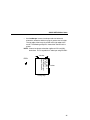
1
Quick Setup Guide
SL5000r and T5000r
RFID Smart Label and Thermal Printers
™
™
NOTICE
This Quick Setup Guide contains a
CD-ROM with the following materials:
• The User’s Manual
• Programmer’s Reference Manuals
• Useful utility programs
The CD-ROM is in a plastic pocket in
the back cover.
Save this guide. If you move or pack
the printer in the future, you will need to
follow the instructions in this guide.
Software License Agreement
CAREFULLY READ THE FOLLOWING TERMS AND CONDITIONS BEFORE USING THIS PRINTER.
USING THIS PRINTER INDICATES YOUR ACCEPTANCE OF THESE TERMS AND CONDITIONS. IF YOU
DO NOT AGREE TO THESE TERMS AND CONDITIONS, PROMPTLY RETURN THE PRINTER AND ALL
ACCOMPANYING HARDWARE AND WRITTEN MATERIALS TO THE PLACE YOU OBTAINED THEM, AND
YOUR MONEY WILL BE REFUNDED.
Definitions.
“Software” shall mean the digitally encoded, machine-readable data and program. The term “Software
Product” includes the Software resident in the printer and its documentation. The Software Product is licensed
(not sold) to you, and Printronix, Inc. either owns or licenses from other vendors who own, all copyright, trade
secret, patent and other proprietary rights in the Software Product.
License.
1.
2.
3.
Authorized Use. You agree to accept a non-exclusive license to use the Software resident in the printer
solely for your own customary business or personal purposes.
Restrictions.
a.
To protect the proprietary rights of Printronix, Inc., you agree to maintain the Software Product and
other proprietary information concerning the typefaces in strict confidence.
b.
You agree not to duplicate or copy the Software Product.
c.
You shall not sublicense, sell, lease, or otherwise transfer all or any portion of the Software Product
separate from the printer, without the prior written consent of Printronix, Inc.
d.
You may not modify or prepare derivative works of the Software Product.
e.
You may not transmit the Software Product over a network, by telephone, or electronically using any
means; or reverse engineer, decompile or disassemble the Software.
f.
You agree to keep confidential and use your best efforts to prevent and protect the contents of the
Software Product from unauthorized disclosure or use.
Transfer. You may transfer the Software Product with the printer, but only if the recipient agrees to accept
the terms and conditions of this Agreement. Your license is automatically terminated if you transfer the
Software Product and printer.
Limited Software Product Warranty
Printronix, Inc. warrants that for ninety (90) days after delivery, the Software will perform in accordance with
specifications published by Printronix, Inc. Printronix, Inc. does not warrant that the Software is free from all
bugs, errors and omissions.
Remedy
Your exclusive remedy and the sole liability of Printronix, Inc. in connection with the Software is replacement
of defective software with a copy of the same version and revision level.
Disclaimer of Warranties and Limitation of Remedies
1.
THE PARTIES AGREE THAT ALL OTHER WARRANTIES, EXPRESS OR IMPLIED, INCLUDING
WARRANTIES OF FITNESS FOR A PARTICULAR PURPOSE AND MERCHANTABILITY ARE
EXCLUDED.
Printronix, Inc. does not warrant that the functions contained in the Software will meet your requirements
or that the operation of the Software will be uninterrupted or error free.
Printronix, Inc. reserves the right to make changes and/or improvements in the Software without notice at
any time.
2.
IN NO EVENT WILL PRINTRONIX, INC. BE LIABLE FOR LOST PROFITS, LOST DATA, BUSINESS
INTERRUPTIONS, OR ANY OTHER DIRECT, INDIRECT, INCIDENTAL OR CONSEQUENTIAL
DAMAGES ARISING OUT OF THE USE OF OR INABILITY TO USE THIS PRODUCT, EVEN IF
PRINTRONIX, INC. HAS BEEN ADVISED OF THE POSSIBILITY OF SUCH DAMAGES, OR ANY
DAMAGES CAUSED BY THE ABUSE OR MANIPULATION OF THE SOFTWARE. SOME STATES DO
NOT ALLOW THE EXCLUSION OR LIMITATION OF LIABILITY FOR CONSEQUENTIAL OR
INCIDENTAL DAMAGES, SO THE ABOVE LIMITATION MAY NOT APPLY TO YOU.
3.
Printronix, Inc. will not be liable for any loss or damage caused by delay in furnishing a Software Product
or any other performance under this Agreement.
4.
Our entire liability and your exclusive remedies for our liability of any kind (including liability for
negligence except liability for personal injury caused solely by our negligence) for the Software Product
covered by this Agreement and all other performance or nonperformance by us under or related to this
Agreement are limited to the remedies specified by this Agreement.
5.
California law governs this Agreement.
Termination of License Agreement
This License shall continue until terminated. This license may be terminated by agreement between you and
Printronix, Inc. or by Printronix, Inc. if you fail to comply with the terms of this License and such failure is not
corrected within thirty (30) days after notice. When this License is terminated, you shall return to the place you
obtained them, the printer and all copies of the Software and documentation.
U.S. Government Restricted Rights
Use, duplication or disclosure by the Government is subject to restrictions as set forth in the Rights in
Technical Data and Computer Software clause at FAR 242.227-7013, subdivision (b) (3) (ii) or subparagraph
(c) (1) (ii), as appropriate. Further use, duplication or disclosure is subject to restrictions applicable to
restricted rights software as set forth in FAR 52.227-19 (c) (2).
Acknowledgement of Terms and Conditions
YOU ACKNOWLEDGE THAT YOU HAVE READ THIS AGREEMENT, UNDERSTAND IT, AND AGREE TO
BE BOUND BY ITS TERMS AND CONDITIONS. NEITHER PARTY SHALL BE BOUND BY ANY
STATEMENT OR REPRESENTATION NOT CONTAINED IN THIS AGREEMENT. NO CHANGE IN THIS
AGREEMENT IS EFFECTIVE UNLESS WRITTEN AND SIGNED BY PROPERLY AUTHORIZED
REPRESENTATIVES OF EACH PARTY. BY USING THIS PRINTER, YOU AGREE TO ACCEPT THE
TERMS AND CONDITIONS OF THIS AGREEMENT.
Communication Notices
This equipment has been tested and found to comply with the limits for a Class B digital device, pursuant to
Part 15 of the FCC Rules. These limits are designed to provide reasonable protection against harmful
interference in a residential installation. This equipment generates, uses, and can radiate radio frequency
energy and, if not installed and used in accordance with the instructions, may cause harmful interference to
radio communications. However, there is no guarantee that interference will not occur in a particular
installation. If this equipment does cause harmful interference to radio or television reception, which can be
determined by turning the equipment off and on, the user is encouraged to try to correct the interference by
one or more of the following measures:
•
•
•
•
Reorient or relocate the receiving antenna.
Increase the separation between the equipment and receiver.
Connect the equipment into an outlet on a circuit different from that to which the receiver is connected.
Consult the dealer or an experienced radio/TV technician for help.
Unauthorized changes or modifications could void the user’s authority to operate the equipment.
This device complies with part 15 of the FCC Rules. Operation is subject to the following two conditions: (1)
this device may not cause harmful interference, and (2) this device must accept any interference received,
including interference that may cause undesired operation.
Any change or modification to this product voids the user’s authority to operate it per FCC Part 15 Subpart A
Section 15.21 regulations.
This product contains an intentional radiator with the following parameters:
Operating Frequency: 902 to 928 MHz
Typical RF Power: 25 to 100 milliwatts (SL5x04 MP) or 25 to 205 milliwatts (SL5x04 C1)
Maximum RF Power: 1 Watt under abnormal conditions
Printronix SL5000r and T5000r
Tested To Comply
With FCC Standards
FOR HOME OR OFFICE USE
Canada
This Class B digital apparatus complies with Canadian ICES-003 and RSS 210.
Cet appareil numérique de la classe B est conforme à la norme NMB-003 du Canada.
Operation is subject to the following two conditions: (1) this device may not cause interference, and (2) this
device must accept any interference, including interference that may cause undesired operation of the device.
This device has been designed to operate with the antennas listed below, and having a maximum gain of
–18 dBi. Antennas not included in this list or having a gain greater than –18 dBi dB are strictly prohibited for
use with this device. The required antenna impedance is 50 ohms.
To reduce potential radio interference to other users, the antenna type and its gain should be so chosen that
the equivalent isotropically radiated power (e.i.r.p.) is not more than that permitted for successful
communication.
CE Notice (European Union)
Marking by the CE symbol indicates compliance of this Printronix system to the EMC Directive and the Low
Voltage Directive of the European Union. Such marking is indicative that this Printronix system meets the
following technical standards:
•
EN 300 220-1 (2000), Electromagnetic Compatibility and Radio Spectrum Matters; Short Range Devices;
Radio equipment to be used in the 25 MHz to 1000 MHz frequency range with power levels ranging up to
500 mW.
•
EN 55022 — “Limits and Methods of Measurement of Radio Interference Characteristics of Information
Technology Equipment.”
•
EN 50082-1: 1992 — “Electromagnetic compatibility—Generic immunity standard Part 1: Residential,
commercial, and light industry.”
•
EN 60950 — “Safety of Information Technology Equipment.”
This printer is a Class B product for use in a typical Class B domestic environment.
CE Symbol
Declaration Of Conformity
Manufacturer:
Printronix, Inc.
14600 Myford Rd.
Irvine, CA 92623 U.S.A.
declares that the product:
Product Type:
Information Technology Equipment, Printer
Equipment Class:
Commercial and Light Industrial
Model Numbers:
T5204r, T5304r, SL5204r, SL5304r, 5504-R40 with optional suffixes
Configuration:
serial, parallel, coax, twinax, external LAN, Ethernet, Wireless Ethernet, RFID
conforms to the following standards:
Safety:
EN 60950-1: 2001, First Edition
EMC:
ETSI EN 301 489-1
ETSI EN 301 489-3
ETSI EN300 220 V1.3.1 Sec. 8.1, 8.2, 8.6, 8.7, 8.9
EN 55022: 1998 +A1 Class B
EN 55024: 1998
EN 61000-4-2
EN 61000-4-3
EN 61000-4-4
EN 61000-4-5
EN 61000-4-6
EN 61000-4-8
EN 61000-4-11
EN 61000-3-2: 2000
EN 61000-3-3: 1995 +A1
and complies with:
The Low Voltage Directive 73/23/EEC and the EMC Directive 89/336/EEC.
Taiwan
Lithium Battery Warning
The controller board contains a lithium battery sealed inside the real-time clock chip. Do not disassemble the
chip to replace the battery. Do not dispose of the chip by incineration. Failure to comply may cause the battery
to explode. Contact your local waste agency for the correct disposal procedure.
Printronix makes no representations or warranties of any kind regarding this material, including, but not limited
to, implied warranties of merchantability and fitness for a particular purpose. Printronix shall not be held
responsible for errors contained herein or any omissions from this material or for any damages, whether
direct, indirect, incidental or consequential, in connection with the furnishing, distribution, performance or use
of this material. The information in this manual is subject to change without notice.
This document contains proprietary information protected by copyright. No part of this document may be
reproduced, copied, translated or incorporated in any other material in any form or by any means, whether
manual, graphic, electronic, mechanical or otherwise, without the prior written consent of Printronix.
COPYRIGHT © 2005 PRINTRONIX, INC. All rights reserved.
Trademark Acknowledgements
Printronix and PGL are registered trademarks of Printronix, Inc.
SL5000r and T5000r are trademarks of Printronix, Inc.
Table of Contents
Unpacking And Installing The Printer ................................. 11
Unpacking The Printer ................................................. 11
Removing The Internal Packing Material ..................... 12
Installation .................................................................... 13
Controls And Indicators ...................................................... 14
Power Switch ............................................................... 14
Control Panel ............................................................... 14
Loading Media And Ribbon ................................................ 18
Loading Roll Media ...................................................... 19
Loading Ribbon ............................................................ 24
Printing Adjustments........................................................... 27
Printhead Pressure Adjustment ................................... 27
Printhead Pressure Block Adjustments ........................ 27
Positioning The Media Sensors ................................... 28
Calibrating The Printer........................................................ 30
Running Auto Calibrate ................................................ 30
Making A Media Profile Printout ................................... 32
Changing The Active IGP Emulation .................................. 37
Configuring The Printer....................................................... 37
QUICK SETUP Menu ......................................................... 38
QUICK SETUP Menu Items ......................................... 40
Saving The Configuration ................................................... 50
Auto Save Configuration..................................................... 50
Selecting The Power-Up Configuration .............................. 51
Loading A Saved Configuration .......................................... 51
Printing A Configuration...................................................... 52
Run A Barcode Demo Test................................................. 53
9
Table of Contents
Cleaning ..............................................................................54
Exterior..........................................................................54
Interior ...........................................................................54
General Cleaning ..........................................................54
Cleaning The Printhead, Platen Roller,
And Media Sensors.......................................................54
Repacking The Printer.........................................................58
Contact Information .............................................................60
Printronix Customer Support Center .............................60
Printronix Supplies Department ....................................60
Corporate Offices ..........................................................61
For More Information ...........................................................61
10
Unpacking And Installing The Printer
NOTE: This Quick Setup Guide covers both the SL5000r and
T5000r printers.
The SL5000r is a smart label printer: it is equipped with an
RFID encoder and has the “RFID Smart” logo near the
control panel.
The 4 and 6 inch T5000r printers do not come equipped
with RFID encoders, but are field upgradable to SL5000r
printers.
The 8 inch T5000r printer is currently not RFID compatible.
Unpacking The Printer
The printer is shipped in a carton and protective bag. Keep all
packing material in case shipping is required.
CAUTION
Avoid touching the electrical connectors to prevent
electrostatic discharge damage while setting up the printer.
The discharge of accumulated electrostatic energy can
damage or destroy the printhead or electronic components
used in this device.
CAUTION
Do not place the printer on its backside during unpacking or
handling, because damage to the printer interface connector
may occur.
11
Unpacking And Installing The Printer
Removing The Internal Packing Material
Remove the tape strips and foam pads from the printer as indicated
below. (The top lid of the shipping carton also displays these
instructions.)
NOTE: Save the foam pads for repacking the printer.
a
Tape Strip (2)
b
Foam Pad (2)
Foam Pad
c
Open
Foam Pad
12
Installation
Installation
AC Power
Receptacle
Power Switch
1. Place the printer on a flat level surface that allows easy access
to all sides of the printer.
CAUTION
Never operate the printer on its side or upside down.
2. Make sure the printer power switch is in the Off (O) position.
WARNING
Failure to properly ground the printer may result in electric
shock to the operator.
In compliance with international safety standards, this printer
has been equipped with a three-pronged power cord. Do not
use adapter plugs or remove the grounding prong from the
cable plug. If an extension cord is required, ensure that a
three-wire cable with a properly grounded plug is used.
3. Attach the AC power cord to the AC power receptacle in the
back of the printer.
CAUTION
Verify the required voltage on the printer’s model number label
on the back of the printer.
4. Attach the AC power cord to a grounded (three prong) electrical
outlet of the proper voltage.
13
Controls And Indicators
Controls And Indicators
Power Switch
The power switch is located on the bottom back panel of the printer.
To apply power, place the switch in the | (On) position. When you
first power on the printer, a series of initialization messages
appears on the Liquid Crystal Display (LCD) on the control panel.
To remove power, place the power switch in the O (Off) position.
Control Panel
The control panel is located on the front of the printer and includes
an LCD, indicators, and control keys (buttons). These are described
in the following tables.
Online Status
Indicator
Liquid Crystal
Display (LCD)
Job In Process
Indicator
14
Description
Indicates when the
printer is online,
offline, or when
there is a fault
condition.
A backlighted
liquid crystal
display with two
rows of 16
characters each.
Indicates when the
printer is receiving
or processing
data.
Indicator
Online Status
Liquid Crystal
Display (LCD)
Job In
Process
During a fault condition,
displays the specific
fault message and the
corrective action.
None
Displays “OFFLINE.”
During a fault condition,
displays the specific
fault message and the
corrective action.
Flashes when receiving
data.
Stays lit when data has
been processed and is
waiting to be printed.
Off when no data is
being received or when
no data remains in the
buffer.
Displays “ONLINE,” the
interface type, and
emulation in use.
During a fault condition,
displays the specific
fault message and the
corrective action.
Flashes when receiving
data.
Stays lit when data has
been processed and is
waiting to be printed.
Off when no data is
being received or when
no data remains in the
buffer.
Displays “OFFLINE”
and a main menu,
submenu, or option.
Flashes during a fault
condition.
Flashes during a fault
condition.
Flashes during a fault
condition.
Off.
Function in
Menu Mode
Off when the printer is
offline.
Function in
Offline Mode
Stays lit when the
printer is online, ready
to print, and accept
data from the host.
Function in
Online Mode
Control Panel
Status And Display Indicators
15
16
+
–
Button
INCREMENT Key in
Menu mode
TEST PRINT Key
Pressing the ↵
(ENTER) key with a
Diagnostic Test
displayed initiates the
test. Pressing ↵ again
terminates the test.
UP Key in Menu mode
FEED Key
None
Advances the
media one label
length.
None
JOB SELECT Key
DECREMENT Key in
Menu mode
Sets printer to
Offline mode.
Function in
Online Mode
PAUSE Key
Toggles the printer
between Online and
Offline modes.
Description
Scrolls through the Test
Print patterns.
Advances the media one
label length.
Displays the name and
number of the last loaded
configuration and allows
you to load the factory and/
or pre-stored printer
configurations.
Sets printer to Online mode.
Function in
Offline Mode
Scrolls right through main
menus.
Increments option values
within submenus.
Scrolls the current menu
selection one level up.
Scrolls left through main
menus.
Decrements option values
within submenus.
Sets printer to Offline mode.
Function in
Menu Mode
Controls And Indicators
Control Panel Keys
Button
Selects the
Menu mode.
None
None
ENTER Key
Pressing the ↵ (ENTER) key in
Menu mode selects the
displayed option or value. An
asterisk then appears next to
the option or value indicating it
has been selected.
Note: If the ENTER key is
locked, “ENTER SWITCH
LOCKED” displays on the LCD
for one second. Press the ↓
(DOWN) and ↵ (ENTER) keys
at the same time to unlock the
ENTER key.
Clears all data
in the printer
data buffer
when enabled.
Function in
Offline Mode
Takes the printer Offline and
selects the Menu mode.
None
Function in
Online Mode
MENU Key
DOWN Key in Menu mode
CANCEL Key
When the CANCEL key is
enabled, pressing it will clear all
data in the printer buffer and
prevent printing of that data.
Note: The default = Disable.
However, when the Coax/
Twinax Interface option is
installed, the default = Enable.
Description
Selects the current
menu value and
displays an asterisk
(*) next to the value.
Scrolls between main
menu selections.
Scrolls the current
menu selection one
level down.
Function in
Menu Mode
Control Panel
Control Panel Keys (cont.)
17
Loading Media And Ribbon
Loading Media And Ribbon
IMPORTANT
18
Printronix recommends using the supplied roll of 100 labels to
set up and verify printer operation. If you have an SL5000r, this
will avoid expending the more expensive smart labels for this
task.
CAUTION
DO NOT TOUCH the printhead or the electronic components
under the printhead assembly.
CAUTION
Do not close the pivoting deck without label stock installed
between the printhead and the platen, because debris on the
platen may damage the printhead.
Loading Roll Media
Loading Roll Media
Media Hanger
Media Hanger
Guide
Pivoting
Deck
Deck Lock
Lever
IMPORTANT
If you are using direct thermal mode, clean the printhead,
platen roller, and upper and lower media sensors every time
you change the media. See “Cleaning” on page 54.
1. Slide the media hanger guide outward to the end of the media
hanger, and flip it up into the horizontal position (as shown).
2. Open the pivoting deck by rotating the deck lock lever fully
clockwise.
19
Loading Media And Ribbon
Media Roll
Media Hanger
Media Hanger
Guide
Media Width
Guide
Media Damper
3. Slide the media width guide close to the outside end of the
media damper.
4. Slide the supplied media roll onto and towards the back of the
media hanger.
5. Place the media hanger guide under the media hanger and
against the lower part of the label core at a 45 degree angle
(as shown). This position provides the required tension for a
new label roll and the desired drag for a partial label roll.
20
Loading Roll Media
Media and
Ribbon Loading
Instructions
Media
Printhead
Media Damper
Platen
6. Thread the media under the media damper and then between
the platen (rubber drive roller) and the printhead.
You can also refer to the arrows on the printer frame or to the
label inside the media cover for media loading instructions.
21
Loading Media And Ribbon
Lower
Media Sensor
Fixed
Guide
Media Width
Guide
Media
Guard
Media
Damper
7. Verify that the left edge of the media is against the fixed guide
on the bottom of the media damper.
8. Push the media width guide in until it is flush with the outer
edge of the media.
9. Check the horizontal position of the lower media sensor
(located under the media guard) and the upper media sensor
(shown on page 27). (See “Positioning The Media Sensors” on
page 28.)
22
Loading Roll Media
Notch
Media (left edge)
10. Align the left (inside) edge of the media with the notch located
in the left front edge of the tear bar.
Pivoting
Deck
Deck Lock
Lever
11. Close the printhead by pressing down on the pivoting deck and
rotating the deck lock lever fully counterclockwise.
12. Power on the printer (place the power switch in the | position).
23
Loading Media And Ribbon
Loading Ribbon
Ribbon
Take-Up Core
Spindle
Flange
Ribbon
Take-Up Spindle
Ribbon
Roll
Pivoting
Deck
Ribbon
Supply Spindle
Deck Lock Lever
IMPORTANT
Clean the printhead, platen roller, and upper and lower media
sensors every time you change the ribbon. See “Cleaning” on
page 54.
1. Install the ribbon take-up core on the ribbon take-up spindle.
NOTE: The first ribbon take-up core comes with the printer.
Thereafter, use the core from the old (used up) ribbon.
2. Slide the ribbon roll onto the ribbon supply spindle until it stops
against the spindle flange.
3. Open the pivoting deck by rotating the deck lock lever fully
clockwise until the deck swings upward.
24
Loading Ribbon
Ribbon
Printhead
Media
Rear Ribbon Guide Roller
4. Thread the end of the ribbon under the rear ribbon guide roller,
then between the platen and the printhead.
You can also refer to the arrows on the printer frame or to the
upper-right corner of the label inside the media cover for ribbon
loading instructions.
25
Loading Media And Ribbon
Media and
Ribbon Loading
Instructions
Ribbon
Take-up Core
Ribbon
Take-up Spindle
Deck Lock Lever
IMPORTANT
Do not attach the ribbon to the ribbon take-up spindle without
a ribbon take-up core installed.
5. Attach the ribbon to the ribbon take-up core on the ribbon
take-up spindle using the adhesive on the ribbon leader.
6. Manually rotate the spindle clockwise until the clear leader has
passed the printhead.
7. Close the pivoting deck and rotate the deck lock lever fully
counterclockwise.
26
Printhead Pressure Adjustment
Printing Adjustments
Right Pressure
Block
Left
Pressure
Block
Right Pressure
Block Pointer
Right
Pressure
Block
Adjustment
Wheel
Left
Pressure
Block
Handle
Bold Mark
Printhead Pressure
Adjustment Dial
Printhead Cover/
Upper Media
Sensor
Pressure Block
Adjustment Scale
Printhead Pressure Adjustment
Adjust the printhead pressure to the setting of 4.
Printhead Pressure Block Adjustments
Left Pressure Block
Manually adjust the left pressure block so its handle is aligned with
the bold mark on the pressure block adjustment scale.
Right Pressure Block
Use the right pressure block adjustment wheel to position the right
pressure block with its pointer near the right edge of the media in
use.
27
Printing Adjustments
Positioning The Media Sensors
Lower
Media Sensor
(left edge)
Adhesive Label
(left edge)
Lower
Media Sensor
Handle (2)
Your printer is equipped with upper and lower media sensors that
detect the top-of-form position on media with label length indicators
(black marks, gaps, notches, or holes). The media sensors also
detect Paper Out conditions.
Use the handles on the lower media sensor to horizontally position
it so that the left edge of the sensor’s visible red LED is aligned
under the left edge of the adhesive label of the installed media.
The upper media sensor, located in the slot under the printhead
cover (see figure on page 27), should be located directly over the
lower media sensor.
28
Positioning The Media Sensors
If you are using smart labels, the lower media sensor should not be
placed in the path of media features that could cause false gap
detection or paper out faults. Such features are dark pre-printing,
rounded die cut label corners, and extraneous cut-outs.
FEED
Position the lower
media sensor in the
grey shaded area.
Avoid Pre-Printing
Avoid Rounded
Die Cut Label
Corner
29
Calibrating The Printer
Calibrating The Printer
NOTE: If you make any changes to the default configuration menu
items, you will be prompted to save the configuration.
See “Auto Save Configuration” on page 50.
For printers not using smart labels, an Auto Calibrate should be
sufficient to properly calibrate the printer (see next section).
To calibrate printers that are using smart labels:
1. Run an Auto Calibrate to set up initial values (page 30).
2. Make a Media Profile printout (page 32).
3. Make any necessary adjustments to Threshold Range in the
CALIBRATE CTRL menu.
4. Run an Auto Calibrate again (page 30).
5. Make a Media Profile printout again (page 32) to verify the
Threshold Range you selected in step 3 is correct.
6. Save the configuration (page 50).
7. Set the saved configuration as the Power-Up configuration
(page 51).
Running Auto Calibrate
IMPORTANT
Since manufacturing differences in media and ribbon can
decrease the printer’s TOF (top-of-form) sensing reliability,
you must run an Auto Calibrate to provide optimum sensor
threshold values for the installed media and ribbon.
1. Set the printer power switch to | (On). (For the location of the
power switch and various panel keys, refer to “Controls And
Indicators” on page 14.)
2. Press the
..
.
key to enter the QUICK SETUP menu.
NOTE: For a complete description of the QUICK SETUP menu,
see page 38.
3. Press ↓ and ↵ together until ENTER SWITCH / UNLOCKED
displays.
30
Running Auto Calibrate
4. Press ↑ or ↓ until Label Length / 6 inch* displays (default).
5. Press + or – until the value that matches the physical length of
the installed media displays. See “Label Length” on page 42.
NOTE: Selecting the correct Label Length forces Auto Calibrate to
increase media advancement for long labels (to detect
actual gaps, notches, or marks) and decrease media
advancement for short labels.
6. Press ↑ or ↓ until Gap/Mark Sensor / Disable* displays.
7. Press + or – until Gap displays.
NOTE: If you are using smart labels, see “Gap Sensing for Smart
Labels” on page 46.
8. Press ↵. An asterisk (*) displays next to the selected item.
9. Press ↓ until Auto Calibrate / Run Calibrate displays.
10. Press ↵. Media advances until it can accurately detect the label
length indicators and then stops at the top-of-form position. The
Sensed Distance value then displays for one second.
11. Auto Calibrate is successful when the Sensed Distance value
correctly matches that of the installed media. For Gap sensing,
the Sensed Distance value is the physical length of one label
plus the length of one gap.
12. If GAP NOT DETECTED or PAPER OUT displays:
a. Check the horizontal position of the media sensors
(page 28).
b. Make a Media Profile printout to verify that the sensors are
performing properly (page 32).
c.
Press PAUSE and run Auto Calibrate again.
13. Press the PAUSE key to take the printer offline.
14. Press the FEED key several times. Each time you press FEED,
the media should advance one label length and stop.
15. Once the Sensed Distance value and performance is
confirmed, save it to the desired configuration menu as
described on page 50 before powering off the printer.
31
Calibrating The Printer
Making A Media Profile Printout
The Media Profile printout shows the relationship of the Paper Out
Threshold and the Gap/Mark Threshold values, illustrates if and
when each label length indicator is detected, and shows the
difference between the label length indicators and the label. The
profile printout (see figure on page 33) helps you set the thresholds
for difficult media. This includes pre-printed labels, labels with poor
gap/media dynamic range, and smart labels that have embedded
RFID tags.
NOTE: Verify the CALIBRATE CTRL menu Gap/Mark Sensor
option (Disable, Mark, Gap, Advanced Gap, or Advanced
Notch) matches the installed media.
You will need a minimum installed label width of two inches
to support the Media Profile printout.
Ensure the lower media sensor is horizontally positioned to
permit sensing of the label length indicators. See
“Positioning The Media Sensors” on page 28.
Ensure the Print Mode option selected in the QUICK
SETUP menu matches the media installed. Select Direct
for heat sensitive media (no ribbon required) or Transfer for
thermal transfer media (ribbon required).
IMPORTANT
Once Media Profile is initiated, the printer will continue to
advance media and print the profile in landscape orientation
until you press ↵ to stop printing.
1. Press the
mode.
..
.
key to take the printer offline and into Menu
2. Press ↓ and ↵ together until ENTER SWITCH / UNLOCKED
displays.
3. Press
..
.
until CALIBRATE CTRL displays.
4. Press ↓ until Media Profile / Profile Print displays and then
press ↵.
The printer will advance media and continue to print a dynamic
profile image depicting the relationship of the label and any
label length indicators detected.
5. Press ↵ to stop printing.
32
Making A Media Profile Printout
6. Press the PAUSE key until OFFLINE displays.
NOTE: The Gap/Mark and Paper Out Threshold values shown on
the Media Profile printout represent the last values
determined from a successful Auto Calibrate or the factory
default values if no Auto Calibrate was performed.
Gap Sensing
This figure shows a Media Profile printout of a smart label where
Gap/Mark Sensor is set to Gap in the CALIBRATE CTRL menu.
In this example, the gap threshold value the printer selected
(represented by the Gap/Mark dotted line) is too close to the
amplitude of the antenna pulse. This may cause the printer to
falsely use the antenna as the gap (top-of-form).
255
191
127
Paper Out(110)
063
Gap/Mark(052)
000
Detected Amplitude
of the Antenna
Detected Amplitude
of the Gap
33
Calibrating The Printer
To avoid this problem, increase the Threshold Range value to 60%
or 70% in the CALIBRATE CTRL menu (the default is 50%), then
run an Auto Calibrate again (page 30).
NOTE: Any changes to Threshold Range will not take effect until
you run an Auto Calibrate again.
This will raise the Gap/Mark threshold high enough so that the
printer will not falsely use the antenna as the gap (top-of-form).
255
191
127
Paper Out(110)
Gap/Mark(072)
063
000
Detected Amplitude
of the Antenna
34
Detected Amplitude
of the Gap
Making A Media Profile Printout
Advanced Gap Sensing
This figure shows a Media Profile printout of a smart label where
Gap/Mark Sensor is set to Advanced Gap in the CALIBRATE CTRL
menu.
In this example, the gap threshold value the printer selected
(represented by the Gap/Mark dotted line) is too close to the
amplitude of the antenna pulse. If there is an increase in noise or
the opacity of the liner or ribbon, the printer may falsely use the
antenna or noise as the gap (top-of-form).
255
191
127
Paper Out(075)
063
Gap/Mark(030)
000
Detected Amplitude
of the Antenna
Detected Amplitude
of the Gap
35
Calibrating The Printer
To avoid this problem, increase the Threshold Range value to 60%
in the CALIBRATE CTRL menu (the default is 50%), then run an
Auto Calibrate again (page 30).
NOTE: Any changes to Threshold Range will not take effect until
you run an Auto Calibrate again.
This will raise the Gap/Mark threshold high enough so that the
printer will not falsely use the antenna or noise as the gap (top-ofform).
255
191
127
Paper Out(075)
063
Gap/Mark(040)
000
Detected Amplitude
of the Antenna
36
Detected Amplitude
of the Gap
Making A Media Profile Printout
Changing The Active IGP Emulation
The following example shows how to change the active IGP
emulation from IGP/PGL (default) to IGP/VGL using the QUICK
SETUP menu.
1. Set the printer power switch to | (On).
2. Press the
..
.
key to enter the QUICK SETUP menu.
3. Press ↓ and ↵ at the same time until ENTER SWITCH /
UNLOCKED displays.
4. Press ↑ or ↓ until Active IGP Emul / IGP/PGL* displays.
5. Press → until IGP/VGL displays.
NOTE: You can also select PPI/ZGL, PPI/TGL, PPI/IGL,
PPI/STGL, or PPI/DGL.
6. Press ↵. An asterisk (*) displays next to the selected emulation.
7. Press PAUSE. OFFLINE displays.
8. Save the configuration (see “Saving The Configuration” on
page 50).
Configuring The Printer
The printer menu structure consists of main menus and menu
items, and the options available for each menu item. Modifications
to the menu items can be selected and saved using the control
panel. See “Control Panel” on page 14 for information about control
panel keys and navigating the menus.
When you press the ... (Menu) key, the QUICK SETUP menu
displays first. This menu lists the most frequently accessed menu
options.
37
QUICK SETUP Menu
QUICK SETUP Menu
QUICK SETUP
Print Intensity
–3*
–15 to 15
Print Speed
6 ips*
1 to 10 ips 1
Print Mode 2
Transfer*
Direct
Media Handling
Tear-Off Strip*
Tear-Off
Peel-Off
Cut
Paper Feed Shift
0.00 inches* 3
–0.50 to X inches 4
Label Length
4 or 6 inches* 3, 5
00.1 to 99.0 inches 6
Label Width
4.1, 6.6, or 8.5 inches* 3, 5
00.1 to 8.5 inches 5
Ver Image Shift
0.00 inches* 3
–1.00 to X inches 4
Hor Image Shift
0.00 inches* 3
–1.00 to 1.00 inches
Orientation
Gap/Mark Sensor
Auto Calibrate
(cont. on next page)
Portrait*
Disable*
Run Calibrate
Continuous
Landscape
Mark
Inv. Portrait
Gap
Inv. Landscape
Advanced Gap
Advanced Notch
Notes:
* = Default
1
Maximum value depends on the width of the
printer model and printhead.
2
Does not appear for direct thermal only printers.
3
You can change the unit value from inches to
millimeters under Units (in MEDIA CONTROL)
See the User’s Manual for information.
4
Based on the current value setting for the Label
Length menu, up to a maximum of 12.80 inches.
5 Maximum
value depends on the width of the
printer model.
6
38
Maximum value depends on model width and size
of DRAM installed.
Making A Media Profile Printout
QUICK SETUP
(cont. from previous page)
Validator Funct. 1
Enable*
Active IGP Emul
IGP/PGL*
Disable
PPI/ZGL
PPI/TGL
PPI/IGL
Save Config.
1*
1 to 8
Power-Up Config.
Factory*
1 to 8
SMT: Status 2
Disabled*
Enabled
SMT: Sel Toolset 2
Toolset [1]*
Toolset [1] to Toolset [4]
SMT: Select Tool 2, 3
EPC 4
zEPC 5
GTIN 4
zGTIN 5
UPCA 4
zUPCA 5
PPI/STGL
EAN8 4
zEAN8 5
PPI/DGL
EAN13 4
zEAN13 5
IGP/VGL
UCC128 4
zUCC128 5
Notes:
* = Default.
1
Appears only if an online data validator (validator)
is installed.
2
Appears only if an RFID encoder is installed.
3
Undocumented options are reserved for internal
use and future design.
4
Appears only if Toolset [1] is selected under
SMT: Sel Toolset.
5
Appears only if Toolset [2] is selected under
SMT: Sel Toolset.
NOTE: Many QUICK SETUP menu items are available in other
main menus. (Refer to the User’s Manual.)
Changes made in the QUICK SETUP menu are updated in
the other main menus, and vice versa.
39
QUICK SETUP Menu
QUICK SETUP Menu Items
Print Intensity
This menu item specifies the level of thermal energy from the
printhead to be used for the type of media and ribbon installed.
Large numbers imply more heat (thermal energy) to be applied for
each dot. This has a significant effect on print quality. The print
intensity and speed must match the media and ribbon type to obtain
the best possible print quality and bar code grades.
The range is –15 through +15. The default is –3.
Print Speed
This menu item specifies the speed in inches per second (ips) at
which the media passes through the printer while printing.
The range is 2 through 10 ips (in increments of 1 ips).
The default is 6 ips.
NOTE: The maximum print speed varies based on maximum
printer width and dot per inch (dpi) resolution of the
printhead installed (203 or 300 dpi).
Print Mode
This menu item specifies the type of printing to be done.
•
•
Transfer. Indicates thermal transfer printing (ribbon installed).
Direct. Indicates direct thermal printing (no ribbon) and
requires special heat sensitive media.
The default is Transfer, unless your printer is shipped as direct
thermal only (no ribbon motors installed).
NOTE: The Print Mode menu item does not appear for direct
thermal only printers.
40
QUICK SETUP Menu Items
Media Handling
This menu item specifies how the printer will handle the media
(labels or tag stock).
•
Tear-Off Strip. Printer prints on the media and sends it out the
front until the print buffer is empty, then positions the last label
over the tear bar for removal.
•
Tear-Off. After each label is printed, the printer positions the
label over the tear bar and waits for you to tear off the label
before printing the next one (on-demand printing). A “Remove
Label” message displays to remind you to remove the label
before the next one can be printed.
•
Peel-Off. When the optional rewinder is installed, prints and
peels die cut labels from the liner without assistance. The
printer waits for you to remove the label before printing the next
one (on-demand printing). The label liner is rewound on the
internal rewinder. A “Remove Label” message displays to
remind you to remove the label before the next one can be
printed.
•
Cut. When the optional media cutter is installed, it
automatically cuts media after each label is printed or can cut
after a specified number of labels have been printed using a
software cut command. It cuts continuous roll paper, labels, or
tag stock.
NOTE: The Cut option is hidden when RFID Reader is set to
Enable in the RFID CONTROL menu.
•
Continuous. Printer prints on the media and sends it out the
front.
The default is Tear-Off Strip.
41
QUICK SETUP Menu
Paper Feed Shift
This menu item represents the distance to advance a label (+ shift)
or pull back (– shift) when the Tear-Off Strip, Tear-Off, Peel-Off, or
Cut Media Handling option is enabled. The allowable range is –0.50
inches to the current Label Length value setting up to a maximum
of 12.80 inches in 0.01 inch increments.
The default is 0.00 inches.
Label Length
In most applications, the user-selected Label Length will match the
physical label length. Physical label length is the actual label length
of the media installed. Following is a list of different media types:
•
Die cut labels: measurable length of the removable label
(leading edge to trailing edge). This does not include the
liner material or gap.
•
Tag stock with notches or holes: measurable length from
the trailing edge of one notch or hole to the trailing edge of
the next notch or hole.
•
Tag stock with black marks on the underside: measurable
length from the leading edge of one black mark to the
leading edge of the next black mark.
•
Continuous media (no label length indicators): measurable
length should be within + 1 to 2% of the Label Length value
entered.
Label Width
This menu item specifies the label width. The allowable range in
inches is 00.1 to the maximum print width of the printer. The
allowable range in millimeters is 2.5 to the maximum width of the
printer.
Ver Image Shift
This menu item specifies the amount to shift an image up (–) or
down (+) for precise positioning on the label. The actual height of
42
QUICK SETUP Menu Items
the image is not affected by this parameter. The allowable range is
–1.00 inches to the current Label Length value setting, up to a
maximum of 12.80 inches, in 0.01 inch increments.
The default value is 0.00 inches.
Hor Image Shift
This menu item specifies the amount to shift an image left (–) or
right (+) for precise positioning on the label. The actual width of the
image is not affected by this parameter. The allowable range is
–1.00 to +1.00 inches in 0.01 inch increments.
The default value is 0.00 inches.
Orientation
Specifies the image orientation to be used when printing the label.
•
Portrait. The default. Portrait refers to vertical page orientation,
where the height of a page is greater than its width. The top
edge of the image is parallel to the leading edge of the media.
The following example is viewed from the front of the printer.
NOTE: Portrait orientation applies to PGL® and VGL emulations.
This is regarded as Inverse Portrait using PPI/ZGL.
4 inches
FEED
6 inches
The top edge of
the image is
parallel to the
leading edge of
the media.
Leading Edge
43
QUICK SETUP Menu
•
Landscape. Landscape refers to horizontal orientation, where
the width of a page is greater than its height. The top edge of
the image is parallel to the left edge of the media. The following
example is viewed from the front of the printer.
NOTE: Landscape orientation applies to PGL and VGL emulations.
This is regarded as Inverse Landscape using PPI/ZGL.
4 inches
The top edge of
the image is
parallel to the left
edge of the media.
FEED
6 inches
Leading Edge
•
Inv. Portrait. Inverse Portrait refers to vertical page orientation,
where the height of a page is greater than its width. The top
edge of the image is parallel to the trailing edge of the media.
The following example is viewed from the front of the printer.
NOTE: Inverse Portrait orientation applies to PGL and VGL
emulations. This is regarded as Portrait using PPI/ZGL.
Trailing Edge
4 inches
FEED
The top edge of
the image is
parallel to the
trailing edge of the
media.
Leading Edge
44
6 inches
QUICK SETUP Menu Items
•
Inv. Landscape. Inverse Landscape refers to horizontal
orientation, where the width of a page is greater than its height.
The top edge of the image is parallel to the right edge of the
media. The following example is viewed from the front of the
printer.
NOTE: Inverse Landscape orientation applies to PGL and VGL
emulations. This is regarded as Landscape using PPI/ZGL.
4 inches
The top edge of
the image is
parallel to the right
edge of the media.
FEED
6 inches
Leading Edge
45
QUICK SETUP Menu
Gap/Mark Sensor
Specifies the sensor type needed for detecting the top-of-form
position on media with label length indicators (gaps, notches, holes,
or black marks).
•
Disable. Select when using media with no label length
indicators (no gaps, notches, holes, or black marks), or when
you want the printer to ignore all existing label length indicators
on the installed media.
NOTE: When you select Disable, the length of each label is based
on the Label Length value entered.
•
Mark. Select when using media that has horizontal black marks
located on the underside of the label liner or tag stock. The
top-of-form position is the leading edge of the black mark.
•
Gap. Select when using media with a liner space between
die cut labels or when using tag stock with notches or holes as
label length indicators on white background media. The
top-of-form position is the leading edge of the die cut label
(trailing edge of the gap, notch, or hole).
•
Advanced Gap. Select when using media that has liner gaps
between die cut labels with black background. The top-of-form
position is the leading edge of the die cut label (trailing edge of
the gap, notch, or hole).
•
Advanced Notch. Select when using media with notches or
holes that interrupt a black vertical line on the underside of the
media. The top-of-form position is the leading edge of the die
cut label (trailing edge of the gap, notch, or hole).
The default is Disable.
Gap Sensing for Smart Labels
If your smart labels have a horizontal black bar located within each
liner gap, set Gap/Mark Sensor to Gap. When you examine a
Media Profile printout (page 32), you will see that the black bar
provides a much higher amplitude pulse than that of any antenna,
which will provide excellent top-of-form reliability.
46
QUICK SETUP Menu Items
If your smart labels have no horizontal black bar located within each
liner gap, you must choose between Gap and Advanced Gap
sensing. Run an Auto Calibrate (page 30), then make a Media
Profile printout (page 32). Choose the sensing type that provides
the highest liner gap amplitude compared to the amplitude of the
antenna line. If you select Gap sensing, and then see that the
Media Profile printout shows very little amplitude difference for the
liner gap compared to the amplitude of the antenna line, select
Advanced Gap sensing instead.
Advanced Gap sensing (often called transmissive) uses an LED
array for the upper sensor and a receiver in the lower sensor to
detect infrared light through the liner gap. This sensing has the
advantage of detecting the liner gap as a positive amplitude pulse
and the antenna line as a smaller, negative pulse.
Auto Calibrate
This feature is used to improve the sensitivity and reliability of the
media sensor in detecting gaps, notches, holes, or black marks on
the installed media, as well as a Paper Out condition.
NOTE: You must set the correct Label Length to force Auto
Calibrate to increase media advancement for long labels
(to detect actual gaps, notches, or marks) and decrease
media advancement for short labels.
To initiate Auto Calibrate, scroll to the Auto Calibrate menu and
press the ↵ key. The printer will advance media the distance
needed to accurately detect the label length indicators, then stop at
the top-of-form position and momentarily display the Sensed
Distance. This process takes a few seconds and results in an
update of the printer values.
Auto Calibrate is completed successfully when the Sensed
Distance displayed correctly matches that of the installed media.
With Gap or Advanced Gap selected, the Sensed Distance should
match the length from the trailing edge of one gap to the trailing
edge of the next gap (one label + one gap). With Mark selected, the
Sensed Distance should match the length from the leading edge of
one black mark to the leading edge of the next black mark.
Auto Calibrate supports label lengths up to 24 inches.
47
QUICK SETUP Menu
Validator Funct.
This menu appears only if an online data validator (validator) option
is installed.
•
Enabled. The printer commands the validator to begin
scanning bar codes and to report errors. The counters
increment while the validator is enabled.
•
Disabled.The printer will not command the validator to begin
scanning bar codes and no errors will be reported. The
counters will not increment while the validator is disabled.
NOTE: If you save a configuration with the validator enabled,
power down and power up, and the validator is not
connected or not functioning, the error message “Validator
not communicating” displays briefly. The Validator menu
will not display.
If the validator is installed, the default is Enable.
Active IGP Emul
This function allows you to activate any resident IGP emulation
listed in the menu. The default is IGP/PGL.
There are two methods for selecting the desired emulation: directly
from the printer menu or by sending a host command which will
switch the emulation automatically (see the appropriate
Programmer’s Reference Manual for details).
Save Config.
Allows you to save up to eight unique configurations to meet
different print job requirements. This eliminates the need to change
the parameter settings for each new job. The configurations are
stored in memory and will not be lost if you turn off the printer.
The default is 1.
48
QUICK SETUP Menu Items
Power-Up Config.
You can specify the Factory configuration or any one of the eight
possible saved configurations as the power-up configuration.
The default is Factory.
SMT: Status
This menu appears only if an RFID encoder is installed. Refer to
“Software Migration Tools (SMT)” in the RFID Labeling Reference
Manual.
•
Disabled.The printer disables the use of the Software
Migration Tools.
•
Enabled. The printer enables the use of the Software Migration
Tools.
SMT: Sel Toolset
This menu appears only if an RFID encoder is installed. Refer to
“Software Migration Tools (SMT)” in the RFID Labeling Reference
Manual.
•
•
•
Toolset [1]. SMTs for PGL emulation.
Toolset [2]. SMTs for PPI/ZGL emulation.
Toolset [3] and Toolset [4]. Reserved for internal use and
future design.
SMT: Select Tool
This menu appears only if an RFID encoder is installed. Refer to
“Software Migration Tools (SMT)” in the RFID Labeling Reference
Manual.
•
EPC, GTIN, UPCA, EAN8, EAN13, and UCC128. SMTs
displayed if Toolset [1] is selected under SMT: Sel Toolset.
•
zEPC, zGTIN, zUPCA, zEAN8, zEAN13, and zUCC128. SMTs
displayed if Toolset [2] is selected under SMT: Sel Toolset.
NOTE: Undocumented options are reserved for internal use and
future design.
49
Saving The Configuration
Saving The Configuration
After customizing your settings, save them as a configuration:
1. Press the
..
.
key to enter the QUICK SETUP menu.
2. Press ↑ or ↓ until Save Config. / 1* displays.
3. If necessary, press + or – until the desired configuration
displays.
4. Press ↵. Saving Configuration displays briefly.
NOTE: You can specify a 15-character name for your
configuration. See “Name Config (1-8)” in the User’s
Manual.
5. If necessary, set your newly saved configuration as the
Power-Up configuration. See “Selecting The Power-Up
Configuration” below.
Auto Save Configuration
If you make any changes to the default configuration menu items,
you will be prompted to save the changes to “Config #” when you
place the printer online. “#” equals the next available unassigned
configuration number. When prompted, press one of the following
keys:
•
Enter. Saves to Config 1 or the next available Config, and
becomes the power-up config.
NOTE: If all eight Configs are assigned, you will be prompted to
select which Config to overwrite.
•
50
Pause. Changes will be implemented but saved only
temporarily until deliberately saved as a new configuration or
until you power off the printer. All changes will be lost when you
power off the printer.
QUICK SETUP Menu Items
Selecting The Power-Up Configuration
To have a saved configuration automatically loaded when you
power up the printer, set the saved configuration as the Power-Up
configuration:
1. Press the
..
.
key to enter the QUICK SETUP menu.
2. Press ↑ or ↓ until Power-Up Config. / Factory* displays.
3. Press + or – until the desired configuration displays.
4. Press ↵. An asterisk (*) displays next to the selected
configuration.
Loading A Saved Configuration
To use a different configuration, load a saved configuration:
1. Press the PAUSE key until OFFLINE displays.
2. Press the JOB SELECT key until the desired configuration
displays.
3. Press ↵. Loading Saved / Configuration displays.
51
Printing A Configuration
Printing A Configuration
We recommend that you print and store your configurations for
future reference. The printout provides a list of the parameters that
were set when you configured the printer.
To print a configuration:
..
.
1. Press the
key until PRINTER CONTROL displays.
2. Press ↓ and ↵ together until ENTER SWITCH / UNLOCKED
displays.
3. Press ↑ until Admin User displays.
4. Press → until Enable displays.
5. Press ↵ to select it. An asterisk (*) appears next to Enable.
6. Press
..
.
until CONFIG. CONTROL displays.
7. Press ↓ until Print Config. displays.
8. Press + or
– to cycle through the following printout options:
Current*
Factory
Power-Up
All
1 to 8 (customized configurations)
9. When the desired option displays, press ↵. The printer prints
the specified configuration.
NOTE: If the configuration you want to print has not been saved,
CONFIG. DOES NOT EXIST/Save First displays
momentarily.
This message indicates that no configuration menu has
been saved under the configuration value you have
selected and therefore cannot be printed. You must either
select another configuration to print or save a configuration
to that configuration value first (see “Saving The
Configuration” on page 50).
52
QUICK SETUP Menu Items
Run A Barcode Demo Test
IMPORTANT
Printronix recommends using the supplied roll of 100 labels to
set up and verify printer operation. If you have an SL5000r, this
will avoid expending the more expensive smart labels for this
task.
Before you send an actual print job, run a bar code demo test:
1. Press the PAUSE key until OFFLINE displays.
2. Press TEST PRINT until Printer Tests / Barcode Demo
displays.
3. Press ↵. The Barcode Demo test pattern will start and print two
bar codes.
4. Check the test pattern. If necessary, reposition the pressure
blocks to obtain a uniform print quality. In most cases, you will
need to adjust only the right pressure block.
5. If desired, you can run additional printer tests, such as Grey,
Grid, and Checkerboard. See step 1 above to start other tests.
NOTE: These tests run continuously by default. Press ↵ to end the
test.
53
Cleaning
Cleaning
Depending on the media used, the printer may accumulate
residues (media dust, adhesives, etc.) as a by-product of normal
printing. To maintain top printing quality, you should remove these
residues by cleaning the printer periodically.
Exterior
Clean the exterior surfaces with a clean, lint-free cloth. If
necessary, use a mild detergent or desktop cleaning solution.
NOTE: Do not use abrasive cleaning agents or solvents.
Interior
Clean the interior of the printer by removing any dirt and lint with a
soft-bristled, non-metallic brush. Use a vacuum cleaner to remove
the residue.
General Cleaning
Periodically clean all rollers, guides, and assemblies. Use low
pressure air to remove dust in the printer. Use isopropyl alcohol and
a cotton swab to clean any areas where media dust, adhesives, etc.
have accumulated.
Cleaning The Printhead, Platen Roller, And
Media Sensors
NOTE: You do not need to turn off the printer before cleaning the
printhead, platen roller, or media sensors.
Printhead Cleaning
As you use your printer, the printhead may become dirty which can
result in poor print quality. Clean the printhead each time you install
new ribbon (thermal transfer print mode) or install new media
54
Cleaning The Printhead, Platen Roller, And Media Sensors
(direct thermal print mode). Clean the printhead with the cleaning
pen supplied with the printer.
By keeping your printhead clean, you will help maintain its life.
Platen Roller Cleaning
Media dust and adhesive residue on the platen roller can degrade
print quality and cause voids in your label image. Clean the platen
roller at the same time as the printhead.
Use a small amount of isopropyl alcohol on a cloth to clean the
platen roller. With the pivoting deck up the platen roller can be
rotated forward by hand to access and clean its entire surface area.
Media Sensor Cleaning
The upper and lower media sensors should be cleaned to ensure
reliable TOF and Paper Out sensing. Clean the media sensors at
the same time as the printhead.
The upper media sensor (located in the horizontal slot of the
printhead cover) can be wiped clean using a soft cloth. The lower
media sensor, easily seen by its visible red light, is located in the
horizontal slot of the media guard. Remove media dust by
vacuuming or blowing air across the lens cover.
Media Damper Cleaning
The media damper and media width guide (see figure on page 20)
can begin to collect adhesive and paper dust residue that can
prevent proper guiding of labels.
Use a small amount of isopropyl alcohol on a cloth to remove label
adhesive and dust from the underside of the media damper and its
fixed (inbound) guide and from the adjustable (outbound) width
guide.
55
Cleaning
Pivoting
Deck
Printhead
Heating
Elements
A
See page 57.
Peel/Tear Door
Lower Media
Sensor
(with visible
red LED)
Printhead Cover/
Upper Media Sensor
Platen Roller
56
Deck Lock
Lever
Cleaning The Printhead, Platen Roller, And Media Sensors
A
From page 56.
Printhead
Heating
Elements
Upper
Media
Sensor
1. Rotate the deck lock lever clockwise to open the pivoting deck
and remove any media and ribbon (if loaded) to gain access to
the printhead assembly heating element area.
2. Gently rub the felt tip of the cleaning pen or a cotton swab with
isopropyl alcohol across the printhead heating elements (light
brown area).
3. Allow the printhead to dry for one minute before reloading the
media and ribbon.
4. Clean the platen roller.
5. Clean the upper and lower media sensors.
57
Repacking The Printer
Repacking The Printer
CAUTION
Follow all of the repacking instructions carefully, otherwise
the printer could be damaged during shipping.
1. Remove all media and ribbon.
2. Install the foam pads and tape the media cover to the base pan
as shown on page 12.
3. Rotate the printhead pressure adjustment dial fully
counterclockwise to the MIN setting.
4. Close the pivoting deck until the latches catch.
CAUTION
Do not rotate the deck lock lever counterclockwise.
Pivoting Deck
Foam Pad
Printhead Pressure
Adjustment Dial
MIN Setting
Deck Lock
Lever
58
Cleaning The Printhead, Platen Roller, And Media Sensors
5. Pack the printer (taped in its bag) as shown (a).
CAUTION
Pack the printer with the media cover (window side) up.
6. Pack the remaining items as shown (b), and tape the box flaps
closed.
7. Strap the box securely (straps not supplied) before shipping (c).
a
b
Media Cover
(window side)
Up
c
Straps (not
supplied)
59
Contact Information
Contact Information
Printronix Customer Support Center
IMPORTANT
Please have the following information available prior to calling
the Printronix Customer Support Center:
•
•
•
Model number
•
Configuration printout (see “Printing A Configuration” on
page 52)
•
•
•
Is the problem with a new install or an existing printer?
Serial number (located on the back of the printer)
Installed options (i.e., interface and host type if applicable to the
problem)
Description of the problem (be specific)
Good and bad samples that clearly show the problem (faxing of
these samples may be required)
Americas
(714) 368-2686
Europe, Middle East, and Africa
(31) 24 6489 410
Asia Pacific
(65) 6548 4114
http://www.printronix.com/public/servicessupport/default.aspx
Printronix Supplies Department
Contact the Printronix Supplies Department for genuine Printronix
supplies.
Americas
(800) 733-1900
Europe, Middle East, and Africa
(33) 1 46 25 1900
Asia Pacific
(65) 6548 4116
or (65) 6548 4182
http://www.printronix.com/public/supplies/default.aspx
60
Corporate Offices
Corporate Offices
Printronix, Inc.
14600 Myford Road
P.O. Box 19559
Irvine, CA 92623-9559
Phone: (714) 368-2300
Fax: (714) 368-2600
Printronix, Inc.
Nederland BV
P.O. Box 163, Nieuweweg 283
NL-6600 Ad Wijchen
The Netherlands
Phone: (31) 24 6489489
Fax: (31) 24 6489499
Printronix Schweiz GmbH
42 Changi South Street 1
Changi South Industrial Estate
Singapore 486763
Phone: (65) 6542 0110
Fax: (65) 6546 1588
Visit the Printronix web site at www.printronix.com
For More Information
This Quick Setup Guide provides general information for use of
your printer. Refer to the User’s Manual (located on the CD-ROM
included with this book) for more detailed information including:
•
•
•
•
•
•
Other Configuration Menus
Interfaces
Diagnostics and Troubleshooting
Printer Options
Specifications
Glossary of Terms
61
For More Information
62
*178423-001*
178423-001C