1
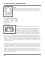
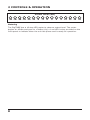
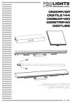
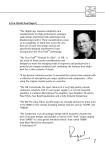
DigiTUBE
Single-Channel Tube Mic-Preamplifier
with S/PDIF Output
USER’S MANUAL 1.1
Copyright © 2001, PreSonus Audio Electronics, Inc.
ALL RIGHTS RESERVED
TABLE OF CONTENTS
1
1.1
1.2
Overview.................................................................................. 1
Introduction ............................................................................... 1
Features .................................................................................... 2
2
2.1
2.1.1
2.1.2
2.2
2.2.1
2.2.2
2.3
2.3.1
2.4
Controls & Operation................................................................ 4
Front Panel................................................................................. 4
Tube Preamp Section ................................................................... 4
Equalizer Section ........................................................................ 6
Back Panel ................................................................................. 9
Digital Section ............................................................................ 9
Analog Section............................................................................ 9
Vacuum Tubes .......................................................................... 12
Replacing the Vacuum Tube ........................................................ 10
Power Supply ........................................................................... 12
3
Technical Specifications ......................................................... 12
4
PreSonus Limited Warranties ................................................. 14
i
OVERVIEW 1
1.1 INTRODUCTION
Thank you for purchasing the PreSonus DigiTUBE Single-Channel Tube MicPreamplifier with S/PDIF Output. This preamp was designed using state of the
art components to deliver crystal clear audio for an indefinate period of time.
We believe the DigiTUBE to be an exceptional sounding unit and an exceptional
value.
Please contact us at 1-800-750-0323 with your questions or comments regarding this product. PreSonus Audio Electronics, Inc. is committed to constant
product improvement and believes the best way to accomplish this task is by
listening to the experts on our gear, our valued customers. We appreciate the
support you have shown us through the purchase of this product.
Please pay close attention to how you connect your DigiTUBE to your system.
Improper grounding is the most common cause of noise problems found in
studio or live sound systems. We urge you to scan this manual before hooking
up your DigiTUBE to familiarize yourself with its features and applications.
Good luck and enjoy your DigiTUBE!
1
1 OVERVIEW
1.2 FEATURES
The following is a summary of your DigiTUBE’s features:
Dual Servo Gain Stage
Your DigiTUBE contains a dual servo gain stage (no capacitors). This design
provides ultra low noise performance and wide dynamic control. The DigiTUBE
can boost the desirable signal without increasing unwanted background noise.
Mic/Instrument/Line Input
The DigiTUBE has a Neutrik™ combo (XLR & 1⁄4”) connector. The XLR input can
be used for microphone signals and phantom power is available for condenser
mics when the 48V switch is engaged. The XLR will also accept line level signals
when the PAD/LINE switch is engaged. The 1⁄4” input will accept instrument level
signals, only. The PAD/LINE switch has no effect on the 1⁄4” input and it should
be understood that the 1⁄4” input is not designed to accept line level signals.
Pad/Line
A switch on the front panel may be used to engage a -20dB pad for mic level
signals or change the XLR input operating level from mic to line. Using the 20dB pad provides a more manageable signal from high output devices giving
the operator greater control over the incoming signal and a much reduced
chance of over-driving the input, thereby avoiding distortion.
48V
The DigiTUBE has 48V phantom power available. Phantom power assures
optimum performance from your condenser microphone without the need of
an external power supply. A 80Hz switch is provided on the front panel of the
DigiTUBE that enables the user to insert an 80Hz filter. Often referred to as a
rumble filter, this feature is useful for eliminating bothersome low-end sounds
such as air conditioning noise without greatly altering the desired audio.
Parametric Equalizer
The equalizer section is equipped with three dual concentric potentiometers
The outer control selects the frequency and the inner control boosts/cuts the
selected frequency. The EQ controls are LOW, MID, HI from left to right. The
bandwidths are broad enough and have enough overlap to allow a very effective
contour of the incoming audio signal.
2
OVERVIEW 1
Drive
The DigiTUBE is provided with a DRIVE potentiometer for controlling the amount
of signal routed through the 12AX7 vacuum tube. This feature lets you control
how much saturation of the signal occurs. Greater levels of tube saturation give
the signal greater warmth and a richer sound. This feature works equally well
on mics and instruments and is just what is needed to tame that ‘brittle’ sound
encountered with different types of digital media.
Internal Clock
An internal clock is provided for 44.1 kHz or 48 kHz operation selectable by way
of the switch on the back panel. An INTERNAL/EXTRERNAL selector and a BNC
connector for external clock input can be found on the back panel as well as the
S/PDIF connector for the DigiTUBE’s digital output.
3
2 CONTROLS & OPERATION
2.1 FRONT PANEL
The front panel of the DigiTUBE contains:
POWER
OUTPUT LEVEL (dBu)
-42 -36 -30 -24 -18 -12
-6
-3
0
3
TUBE PREAMP
5
PAD/
LINE
0
10
DRIVE
MIC/INSTRUMENT
LINE
6
9
12
18
24
EQUALIZER
0
2k
48V
3
15
0
120
24
48
GAIN (dB)
EQ
IN
80Hz
-12 30
LOW
1k+12
0
5k
-12 900
LEVEL
MID
5k+12
-12 3k
15k+12
HIGH
FREQ
The front panel of the DigiTUBE is divided into two sections: the tube preamp
controls are located on the left hand side of the unit’s front panel and the
equalizer section is on the right.
2.1.1 TUBE PREAMP SECTION
Neutrik™ Combo Microphone (XLR) / Instrument (1⁄4”) Input
Drive Control
Pad/Line Switch
Gain Control (3dB - 48dB)
+48V Phantom Power Switch
Mic/Line/Instrument Input
The DigiTUBE has a Neutrik™ combo connector which provides both an XLR and
a 1⁄4” TS input. The XLR connector can accept microphones or by engaging the
PAD/LINE switch, line level signals. The 1⁄4” input is for instrument level signals
only. If you wish to adapt a line level device with a 1⁄4” connector, An XLR
connector with pins 1 and 3 tied together for ground and the hot connected to
pin 2 must be made. This adapts the unbalanced line level cable to input signal
via the XLR input and the PAD/LINE switch to convert the input to accept a line
level signal.
Drive
The DRIVE potentiometer controls how much signal
is routed through the 12AX7 vacuum tube. The effect
M ORE
5
0
4
10
achieved by this procedure can be subtle to extreme,
depending on the setting being used. A ‘warming up’
of the sound can be noticed at lower settings. This
effect can be used to compensate for the harshness commonly encountered in digital signals with
CONTROLS & OPERATION 2
the resulting sound possessing a ‘richer’ and ‘sweeter’ tone. If an overdriven
signal is desired, this can be achieved by significantly raising the level of the
DRIVE control. Overdriving the tube is especially useful for direct electric guitar
sounds. Setting the DRIVE control is a matter of taste; the amount of saturation
needed to achieve a desired result depends upon the resulting sound you want
to hear. Experiment!
Gain
This control is used to determine the amount that a
24
signal being processed by the pre-amplifier is increased
in level at output. Dynamic mics and instruments
without pre-amps may require more gain than condenser mics and instruments that have a built-in
3
48
pre-amp (care should be taken with instruments having
their own built-in pre-amp not to overdrive the 1⁄4”
input of the DigiTUBE). Line level signals can only be processed through the
XLR input connector with the PAD/LINE switch in the LINE position. Attempting to use the 1⁄4” input for line level signals exceeds the design parameters of
the DigiTUBE. The 1⁄4” input of the Neutrik™ connector is designed to accept
instrument level signals and attempting to use the 1⁄4” input for line level will
likely yield an unsatisfactory result. Activating the PAD/LINE switch reduces the
incoming signal by 30dB. This is a very useful feature for rapidly reducing the
level coming into the DigiTUBE to prevent the input signal from over-modulating (distorting). This may occur due to a high output level from a microphone.
Padding the mic input serves to provide increased ‘headroom’ for the operator
and allow greater variance in adjusting the GAIN control. Placing the switch
to the PAD/LINE position allows the XLR connector to accept line level signals.
Line level signals can be used in the XLR input without overdriving the input.
Keyboards and other line level devices can be inserted into the DigiTUBE XLR
input by selecting the LINE position.
M ORE
Note: the PAD/LINE switch does not affect the 1⁄4” input of the Neutrik™
connector. The 1⁄4” input is designed to accept instrument level signals ONLY!
5
2 CONTROLS & OPERATION
1
2
Input
Phantom power is available through the XLR input of the
DigiTUBE. This 48V of phantom power is for condensor mics
and/or any other devices that may require it via XLR inputs.
3
PIN 1 = GND
PIN 2 = + (+48V)
PIN 3 = - (+48V)
2.1.2 EQUALIZER SECTION
Low (30Hz - 1kHz) +/- 12dB
Mid (900Hz - 5kHz) +/-12dB
High (3kHz - 15kHz) +/-12dB
80Hz Switch
EQ IN Switch
LE
SS
E
OR
M
Low
The LOW control is a dual concentric potentiometer
with the outer ring allowing the selected frequency to
be boost or cut by as much as twelve decibels. The
straight up, twelve o’clock, position is labeled zero
30
1k
(0). When the outer control knob is in this position,
-12
+12
no effect is exerted on the signal, regardless of what
frequency is selected with the inner controller. Rotating the outer control knob
to the left or counter-clockwise reduces the selected frequency. Rotating the
outer controller to the right or clockwise increases the selected frequency. The
inner control knob selects the frequency. The LOW EQ control goes from 30Hz
to 1kHz. The control frequency is narrower to the fully counter-clockwise or left
side. As the inner control is rotated clockwise, the frequency bandwidth is much
more broadly defined.
0
120
For example, from the fully counter-clockwise position of 30Hz to the first mark
represents a difference of 10Hz - 15Hz whereas from fully clockwise or 1kHz to
the first marked position back represents as much as a 100Hz difference. The
significance of this to the operator is that a movement of the frequency selector
from a fully counter-clockwise position to approximately the twelve o’clock
position represents smaller incremental frequency changes compared to the frequency changes that occur when the selector travels clockwise past the twelve
o’clock position and beyond.
6
CONTROLS & OPERATION 2
LE
SS
LE
SS
-12 3k
E
OR
M
0
5k
E
OR
M
Mid
The dual concentric potentiometer labeled MID controls
the frequencies from 900Hz to 5kHz. The outer ring
provides boost or cut at the frequency selected by the
inner knob by plus or minus twelve decibels with the
5k+12
straight-up noon position equal to zero or no boost or
-12 900
cut. The inner control knob begins at 900Hz in the left
or fully counter-clockwise position and continues to 5kHz in the right or fully
clockwise position. This control behaves in the same manner as the LOW control
with the frequency widths delineated by the knob’s markings becoming wider as
the knob travels to the right or the clockwise direction.
0
2k
15k+12
High
The Equalizer dual concentric control labeled HIGH
operates in the same manner as the LOW and MID
controller. The inner HIGH control knob is used to
boost or cut frequencies ranging from 3kHz to 15kHz
by as much as 12dB by adjusting the outer ring of the
controller.
80Hz Switch
The DigiTUBE equalizer section contains a switch labeled 80Hz. Engaging this
switch activates an 80Hz filter (often referred to as a rumble filter). This filter is
useful for eliminating extraneous low-end sounds from the signal being amplified. Frequencies from 80Hz and below are cut from the incoming signal. This
will eliminate low-frequency noises such as air-conditioning hum or the sounds
of nearby traffic or other vibrations that may be transmitted through the microphone stand into the microphone. It can also be useful for reducing the effect of
electrical hum that may be the result of grounding problems.
EQ In
The EQ IN switch provides the ability to audition the effect that the equalizer is
having on the signal being processed. Pushing the switch to the latched position
inserts the equalizer into the signal path. Releasing the switch takes the EQ out
of the signal path. You can quickly judge the effect your efforts at adjusting the
equalization of the incoming signal are achieving and rapidly compare it to the
un-equalized signal.
7
2 CONTROLS & OPERATION
OUTPUT LEVEL (dBu)
-42 -36 -30 -24 -18 -12
-6
-3
0
3
6
9
12
15
18
24
Metering
The DigiTUBE has a 16 step LED meter to observe output level. The meter
begins at -42dbu and goes to +24dbu (clip). A red LED is also provided on the
front panel to indicate when the unit has power and is ready for operation.
8
CONTROLS & OPERATION 2
2.2 BACK PANEL
The back panel of the DigiTUBE contains:
Ext. Clock Input
Sleeve = GND
Ring = Input
Tip = Output
POWER
18 VAC
Clock
Sync
DIGITUBE
Created, Designed and
Manufactured In The USA
by PreSonus Audio Electronics, Inc.
S/PDIF
48
44.1
ext.
int.
Insert
Balanced Output
The back panel of the DigiTUBE is divided into a digital and an analog section.
2.2.1 DIGITAL SECTION
S/PDIF Digital Output (RCA)
External Clock Input (BNC)
Clock switch (44.1k and 48k)
Sync switch (Internal and External)
2.2.2 ANALOG SECTION
TRS Insert
The 1⁄4” TRS Insert connector operates at line level.
Tip
Sleeve
Ring
Tip
Sleeve
Ring
TIP = Output
RING = Input
SLEEVE = GND
Cable Wiring Diagram for 1⁄4” TRS Insert
1
2
3
XLR Output Jack
The output XLR connector is servo balanced and operates
at 0 = 0dB. It should be noted that the output signal
available on Channel 1 and Channel 2 are identical mono
outputs, not stereo.
PIN 1 = GND
PIN 2 = High (+)
PIN 3 = Low (-)
9
2 CONTROLS & OPERATION
2.3 VACUUM TUBES
The DigiTUBE comes supplied with a 12AX7 vacuum tube that provides excellent performance characteristics. We encourage owners of the DigiTUBE to try
different brands of 12AX7 vacuum tubes to investigate the various performance
possibilities they might provide.
2.3.1 REPLACING THE VACUUM TUBE
1. Disconnect the DigiTUBE from it’s electrical outlet.
2. Remove the six screws that attach the top of the unit’s chassis. The vacuum
tube is mounted in a horizontal fashion in the middle of the DigiTUBE’s body.
3. Carefully remove the vacuum tube from it’s receptacle. Be sure to hold the
socket in place while gently wiggling the vacuum tube out.
4. Insert the replacement vacuum tube into the receptacle. Care should be
taken to properly align the pins on the vacuum tube to the corresponding holes
in the receptacle. (Caution should also be taken to not break the circuitboard.)
5. Replace the top of the DigiTUBE.
6. Restore power to the unit and resume operation.
Remember, tube life and performance are affected by how often a tube is
used and by how ‘hard’ the tube is driven when in use. Signs of wear may be
exhibited by poor performance or by the tube becoming ‘microphonic’. Periodic
replacement of the vacuum tube is recommended. The time interval for tube
replacement may vary greatly. If you notice deterioration in sound quality then
it’s probably time to change the vacuum tube.
2.4 POWER SUPPLY
This unit is supplied with an external power supply designed to operate at the
required voltage of the country where the retail sale occurred. Use of a power
supply other than one supplied with the unit constitutes an infringement of the
warranty and effectively voids it. Use of an improper power supply may damage
the unit and could pose serious danger of electrical shock or fire.
10
CONTROLS & OPERATION 2
11
4 TECHNICAL SPECIFICATIONS
Number of Channels ............................................................................ One
Performance
THD + Noise (Unweighted) ......................................................0.05% @ 0dB
Tube Drive..............................................................................10% @ 30dB
Noise Floor .....................................................................................-94dBu
Signal to Noise................................................................................ >90dB
Power Supply Rejection .................................................................... >98dB
Amplifier Type ............................................................................Dual Servo
Input
Connectors ....................................................................... Neutrik™ Combo
Input Impedance, XLR .................................................................. 5k Ohms
Input Impedance, High Z 1⁄4”...................................................... 1Meg Ohms
Output
Output Impedance, XLR Balanced ................................................... 51 Ohms
Output Impedance, 1⁄4” TRS Insert ..................................................Tip = Out
Ring = In
Sleeve = GND
Digital...................................................................... S/PDIF RCA Connector
Front Panel Controls
Tube Drive............................................................................ 0dB to +30dB
Gain .......................................................................... 0dB to +40dB - 20dB
Pad...........................................................................+ 48V Phantom Power
EQ..................................................................................... In/Out Selector
Low ........................................................................................30Hz - 1kHz
Mid....................................................................................... 900Hz - 5kHz
High ..................................................................................... 3kHz - 15kHz
Metering
8 Segment LED ............................................................... -28dBu to +18dBu
Power Indicator ................................................................................... LED
Back Panel Controls
Sample Rate Selector..........................................................44.1kHz / 48kHz
Internal / External Clock............................................... 44.1kHz / 48kHz only
12
TECHNICAL SPECIFICATIONS 4
Power Supply
Type ..................................................................................... Linear Supply
Input ................................................................................ 18 VAC/1000mA
Power ..........................................................................................15 Watts
Physical
Weight .............................................................................................. 8lbs.
Size ............................................................................................ Ω U Rack
Dimensions..........................................................................8” X 5” X 1.75”
Mounting..............................................................Universal Rack Tray Insert
Chassis ............................................................................................. Steel
Front Panel .....................................................................Brushed Aluminum
As a commitment to constant improvement, PreSonus reserves the right to change any
specification stated herein at any time in the future without prior notification.
13
5 PRESONUS LIMITED WARRANTY
IN THE UNITED STATES
PreSonus Audio Electronics Inc. warrants this product to be free of defects in material
and workmanship for a period of one year from the date of original retail purchase.
This warranty is enforceable only by the original retail purchaser. To be protected by this
warranty, the purchaser must complete and return the enclosed warranty card within 14
days of purchase. During the warranty period PreSonus shall, at its sole and absolute
option, to either repair or replace, free of charge, any product that proves to be defective
on inspection by PreSonus or its authorized service representative. To obtain warranty
service, the purchaser must first call or write PreSonus at the address and telephone
number printed below to obtain a Return Authorization Number and instructions of where
to return the unit for service. All inquiries must be accompanied by a description of
the problem. All authorized returns must be sent to the PreSonus repair facility postage
prepaid, insured and properly packaged. PreSonus reserves the right to update any unit
returned for repair. PreSonus reserves the right to change or improve the design of the
product at any time without prior notice. This warranty does not cover claims for damage
due to abuse, neglect, alteration or attempted repair by unauthorized personnel, and is
limited to failures arising during normal use that are due to defects in material or workmanship in the product. Any implied warranties, including implied warranties of merchantability
and fitness for a particular purpose, are limited in duration to the length of this limited
warranty. Some states do not allow limitations on how long an implied warranty lasts,
so the above limitation may not apply to you. In no event will PreSonus be liable for
incidental, consequential or other damages resulting from the breach of any express or
implied warranty, including, among other things, damage to property, damage based on
inconvenience or on loss of use of the product, and, to the extent permitted by law,
damages for personal injury. Some states do not allow the exclusion of limitation of
incidental or consequential damages, so the above limitation or exclusion may not apply
to you. This warranty gives you specific legal rights, and you may also have other rights,
which vary form state to state. This warranty only applies to products sold and used in
the United States of America. For warranty information in all other countries please refer
to your local distributor.
PreSonus Audio Electronics, Inc.
7257 Florida Blvd.
Baton Rouge, LA 70806
(225) 216-7887
Copyright © 2001, PreSonus Audio Electronics, Incorporated. All rights reserved.
14
PRESONUS LIMITED WARRANTY 5
OUTSIDE OF THE UNITED STATES
PreSonus Audio Electronics products are warranted only in the country where originally
purchased, through the authorized PreSonus distributor in the country of original purchase,
against defects in material and workmanship. The specific period of this limited warranty
shall be that which is described to the original retail purchaser by the authorized PreSonus
dealer or distributor at the time of purchase. PreSonus does not, however, warrant its
products against any and all defects: 1) arising Out of materials or workmanship not
provided or furnished by PreSonus, or 2) resulting from abnormal use of the product or use
in violation of instructions, or 3) in products repaired or serviced by other than authorized
PreSonus repair facilities, or 4) in products with removed or defaced serial numbers,
or 5) in components or parts or products expressly warranted by another manufacturer.
PreSonus agrees, through the applicable authorized distributor in the country of original
retail purchase, to repair or replace defects covered by this limited warranty with parts
or products of original or improved design, at its option in each respect, if the defective
product is shipped prior to the end of the warranty period to the designated authorized
PreSonus warranty repair facility in the country where purchased, or to the PreSonus
factory in the U.S., in the original packaging or a replacement supplied by PreSonus, with
all transportation cost and full insurance paid each way by the purchaser or owner. All
remedies and the measure of damages are limited to the above services. It is possible that
economic loss or injury to person or property may result from the failure of the product;
However, even if PreSonus has been advised of this possibility, this limited warranty does
not cover any such consequential or incidental damages. Some states or countries do not
allow the limitations or exclusion of incidental or consequential damages, so the above
limitation may not apply to you. Any and all warranties, express or implied, arising by law,
course of dealing, course of performance, usage of trade, or otherwise, including but not
limited to implied warranties of merchantability and fitness for a particular purpose, are
limited to a period of two years from either the date of original retail purchase or, in
the event no proof of purchase date is available, the date of manufacture. Some states
or countries do not allow limitations on how long an implied warranty last, so the above
limitations may not apply to you. This limited warranty gives you specific legal rights, and
you may also have other rights which vary from state to state, country to country.
PreSonus Audio Electronics, Inc.
7257 Florida St.
Baton Rouge, LA 70806
(225) 216-7887
Copyright © 2001, PreSonus Audio Electronics, Incorporated. All rights reserved.
15