1
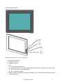
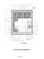
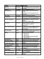
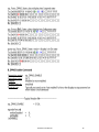
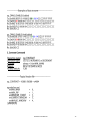
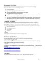
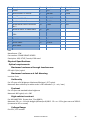
Preface:
This manual is designed for use with the LX1250TI industrial display. Information in this document has
been carefully checked for accuracy; however, no guarantee is given to the correctness of the
contents. The information in this document is subject to change without notice.
The information contained in this document is subject to change without notice. This document
contains proprietary information that is protected by copyright. All rights are reserved. No part of this
document may be reproduced, translated to another language or stored in a retrieval system, or
transmitted by any means, electronic, mechanical, photocopying, recording, or otherwise, with-out
prior written permission.
Windows® is a registered trademark of Microsoft, Inc.
Other brands or product names are trademarks of their respective holders.
Table of Contents
USAGE NOTICE ...................................................................................................................................................................................................................... 4
PRECAUTIONS .......................................................................................................................................................................................................................... 4
ACCESSORY CABLES: .............................................................................................................................................................................................................. 4
PRODUCT ........................................................................................................................................................................................................ 5
PRODUCT HIGHLIGHTS ............................................................................................................................................................................................................. 8
USING THE DISPLAY: ................................................................................................................................................................................ 11
USING REMOTE OSD FEATURES: .......................................................................................................................................................... 11
2.1
DISPLAY CONTROL SERIAL COMMANDS/QUERIES ..................................................................................................................................................... 11
...................................................................................................................................................... 13
2.1.2
DETAILS OF COMMAND IMPLEMENTATION .......................................................................................................................................................... 13
PERFORMANCE CONDITIONS ................................................................................................................................................................ 25
CLEANING GUIDELINES ........................................................................................................................................................................................................ 25
COOLING ............................................................................................................................................................................................................................... 25
FUNCTIONAL SPECIFICATIONS ............................................................................................................................................................. 25
MANUAL DIMMING CONTROL ............................................................................................................................................................................................... 25
USB DIMMING CONTROL ....................................................................................................................................................................................................... 25
AUTO SYNC ........................................................................................................................................................................................................................... 25
VOLUME CONTROL................................................................................................................................................................................................................ 26
FUNCTION BUTTONS ON FRONT OF DISPLAY ......................................................................................................................................................................... 26
LED STATUS LIGHT ............................................................................................................................................................................................................... 26
MODULE SPECIFICATIONS...................................................................................................................................................................... 26
AMLCD ................................................................................................................................................................................................................................ 26
TOUCHSCREEN ...................................................................................................................................................................................................................... 26
VIDEO CONTROLLER BOARD ................................................................................................................................................................................................. 27
PEZIO FUNCTION – LX1250TI ONLY ...................................................................................................................................................................................... 27
MECHANICAL ENCLOSURE ..................................................................................................................................................................................................... 27
CONNECTORS AND I/O........................................................................................................................................................................................................... 27
PHYSICAL SPECIFICATIONS ................................................................................................................................................................... 29
OPTICAL REQUIREMENTS ....................................................................................................................................................................................................... 29
MECHANICAL OUTLINE ......................................................................................................................................................................................................... 30
PRELIMINARY DIMENSIONS ................................................................................................................................................................................................... 30
VESA MOUNT ....................................................................................................................................................................................................................... 31
WEIGHT ................................................................................................................................................................................................................................. 31
SHIPPING BOX ............................................................................................................................................................................................. 31
MAINTENANCE REQUIREMENTS/SERVICE SUPPORT .................................................................................................................... 31
SERVICE REQUIREMENTS ...................................................................................................................................................................................................... 31
SERVICE BOM....................................................................................................................................................................................................................... 31
ENVIRONMENTAL SPECIFICATIONS ................................................................................................................................................... 31
TEMPERATURE ...................................................................................................................................................................................................................... 31
HUMIDITY ............................................................................................................................................................................................................................. 31
ALTITUDE .............................................................................................................................................................................................................................. 31
VIBRATION ............................................................................................................................................................................................................................ 31
SHOCK ................................................................................................................................................................................................................................... 31
REGULATORY COMPLIANCE ................................................................................................................................................................. 32
ELECTROMAGNETIC COMPATIBILITY (EMC) ........................................................................................................................................................................ 32
EMISSIONS ............................................................................................................................................................................................................................. 32
IMMUNITY CHARACTERISTICS ............................................................................................................................................................................................... 32
SAFETY .................................................................................................................................................................................................................................. 32
ROHS COMPLIANCE............................................................................................................................................................................................................. 32
WEEE COMPLIANCE .............................................................................................................................................................................................................. 32
RELIABILITY .......................................................................................................................................................................................................................... 33
INCLUDED IN THE SHIPPING BOX ........................................................................................................................................................ 33
SHIPPING CONFIGURATION (STATE OF MONITOR WHEN SHIPPED) ........................................................................................ 33
PRODUCT ACCESSORIES ......................................................................................................................................................................... 33
PRODUCT SPECIFICATIONS OVERVIEW ............................................................................................................................................ 34
LX1250TI User Manual
3
USAGE Notice
Precautions
To maximize the life and safe use of your unit, always be sure to follow the warnings, precautions and
maintenance recommendations in this user’s guide.
In a Vehicle:
The monitor should be visible to the driver only if it is used for navigation, system control or vehicle
information. If the monitor will be used for other purposes, it should be installed in a way that it will
only operate while the vehicle is not moving (such as when the parking brake is in use), or so that its
display is not visible to the driver. Review all applicable state and local laws and regulations to make
sure the monitor is used properly and safely. Avoid using the monitor for extended times while the
vehicle is not running, or the monitor could drain the vehicle’s battery.
Cleaning the Monitor:
Always turn of the unit before cleaning. Use a soft cloth moistened with mild detergent, isopropyl
alcohol, or window cleaners to clean the display housing. Never use abrasive cleaners, waxes or
solvents to clean the unit.
Accessory Cables:
The LX1250TI (PN# 997-6186-00LF) requires a special interface cable. This manual contains information
to design the interface cable OR an accessory interface cable can be purchased.
PN#. 997-5886-00LF GlenAir to VGA, Power, USB & Audio
For remote control: Download USB to RS232 Driver from Planar website at
http://www.planar.com/support/
LX1250TI User Manual
4
Introduction
About Planar’s LX1250TI Rugged Touch Monitor
The LX1250TI is a high-performance, rugged touch monitor intended for demanding environments,
such as those inside mining vehicles. The monitor features a 12.1-inch diagonal liquid crystal display
with XGA resolution, bright enough to be read in full sunlight. The monitor also includes a buzzer for
audio feedback and a sturdy cast aluminum enclosure that can withstand shock and vibration.
Product
This manual applies to product
Planar Part Number
Planar Model Name
Description
UPC
997-6186-00LF
LX1250TI
IR touch 12.1” XGA LCD
General Market
8 10689 06186 1
997-6192-00LF
LX1251TI
IR Touch 12.1” XGA LCD
General Market –VGA IF
8 10689 06192 2
LX1250TI User Manual
5
Figure 1 Rendering of the display
1
2
3
4
Reference Document # 076-0672-00 for detailed drawings.
Front View (Descriptions):
1. Backlight control +
2. Backlight Control –
3. LED:
Green When video present;
Amber when there is no video signal present and the monitor will go into standby mode.
LED remains Amber in Standby Mode
Off – no power to display.
4. Power Switch Pass through for remote PC shutdown. N.O. SPST switches (not Monitor Power)
an external device.
LX1250TI User Manual
6
All mounting & strain relief holes M4 x 8 mm
LX1250TI User Manual
7
Product highlights
Designed for demanding transportation environment
Optimized for in cab sunlight viewability
One button Display/CPU power on/off
Control of backlight dimming and other OSD functions though USB interface
Wide Voltage input with transient protection
Low EMI
Wide operating temperature range without fans or ventilation
Vibration and Shock tested to rugged transportation specifications
Waterproof enclosure design
Rugged Aluminum enclosure
12.1” XGA high bright display for viewability in all environments
Infrared touchscreen with strengthened glass touch surface for the best optical clarity
Wide dimming range controlled via USB or Bezel buttons
Fanless die cast aluminum chassis with an IP65 design
Single integrated Mil-Std connector for all connections
Also available with separate VGA, Power, and USB connectors
LED backlight for increased ruggedness, lower power, better EMI performance, better
environmental impact (no mercury) and to minimize overall monitor depth and weight
Hazardous materials compliant for international deployment
Features:
Brightness control allows you to easily adjust the display to match ambient light, from full
sunlight to nigh. Even while wearing gloves. The convenient buttons enable quick
adjustments.
The monitor’s optically bonded display reduces the effects of reflected light on the display,
increasing contrast ratio and read-ability in high ambient lighting conditions.
The monitor’s autosync function eliminates the need for adjusting the monitor for best
image. The monitor automatically adjusts to the input signal.
HID Compliant IR Touch screen provides a durable touch environment that allows for
operation in all conditions including with gloved hands. HID compliance means no touch
drivers required.
The monitor supports standard VGA input signals – native 1024 x 768 (XGA) as well as 800 x
600 (SVGA) and 640x480 VGA.
The aluminum enclosure has a waterproof front and is designed to withstand substantial
shock and vibration.
LX1250TI User Manual
8
Package Overview
The following items are shipped with the display:
Monitor
Quick Start Guide
NOTE: No cables ship with the monitor. Cables are purchased separately.
Installation
Before Installing
Keep the following in mind while installing the monitor.
• The monitor should be visible to the driver only if it is used for navigation, system control or vehicle
information. If the monitor will be used for other purposes, it should be installed in such a way that it
will only operate while the vehicle is not moving (such as when the parking brake is in use). Review all
applicable state and local laws and regulations to make sure the monitor is used properly and safely.
• The installed monitor must not interfere with the driver’s vision.
Installing the LX1250TI monitor consists of three steps:
1. Testing Touch Screen functionality with application software - see page 26.
2. Securely routing the interface cable
3. Mounting the monitor using one of the mounting options available on the back of the display
enclosure. - see page 31.
4. Connecting the monitor to the computer and power source - see page 17
Note: The touch sensor is factory tested & calibrated, however different computing environments may
require the touch screen to be recalibrated. Windows & Linux tools can be downloaded at:
For Windows Support: http://www.irtouch.com/shtml/20091124180041.shtml
For Linux Support: http://www.irtouch.com/shtml/2009129110904.shtml
No standard On Screen Display (OSD) buttons are available to the user: All ‘standard’ OSD
functionality can be controlled via the remote interface.
The user controls are limited to Backlight +/- & Remote Power buttons.
The All-in-One power button: A power button located on the front of the display functions as a
pass though to turn on and off a remote computer. It functions very similar to a laptop
computer docking station power button. The button is a Normally Open, Single Pull Single
Throw Switch. It is not designed for current carrying switching.
When there is no video detected, the monitor will go into standby mode. The LED will remain in
Amber state in Standby Mode.
No Base, mounting brackets, or stand is shipped with this device. It is a monitor head only.
LX1250TI User Manual
9
No cables or power supply are shipped with this monitor, they are available as accessories for order
separately.
Electrical & SW Installation:
Prior to end unit installation verify display works with computing system.
1. Power up display:
a. Display requires 9-32V DC with a maximum of 1.88A
2. Test touch functionality. Connect cable to display and apply power.
3. Connect Display to a computer.
4. Display should auto sync to source signal. Ensure source meets supported display resolutions
(XGA, SVGA, VGA).
5. Connect USB touch screen to display.
a. If Windows PC, PC should auto detect and configure touch sensor as HID compliant
device.
6. Verify touch response and accuracy.
a. If Touch alignment is reversed install Touch calibration tools
NOTE: Touch screen is calibrated at factory. Some computer interfaces may require recalibration at
installation. Regular Calibration is not required.
7. Once monitor is verified working with PC proceed to mechanical installation.
Mechanical Installation:
Display may be mounted in several configurations.
a) Panel mounting
b) VESA 100 or 75mm
c) RAM 34.5mm x 40mm Triangle mount.
If Vibration is a concern, consider mounting display using vibration dampening mount.
1
Choose mounting option & Location
2
Refer to dimensions figure for mounting holes and locations.
3
Attach display to mounting hardware.
4
Rout cable.
NOTE: GlenAir cable should be mounted with strain relief to avoid excessive loading or
torquing of the cable connectors. Improper cable installation will void warranty.
LX1250TI User Manual
10
Using the display:
1. Once installed and cabled. The display is ready to use.
2. Apply system power.
3.
Display & Touch screen are active
Using the Touchscreen
1. The LX1200TI touchscreen allows you to operate the computer by touching the screen with a
I nger or stylus, rather than using a mouse or keyboard.
2. Navigating the Touchscreen
•
To click an item, tap the item once.
•
To double-click an item, tap the item twice rapidly.
•
To drag an item, touch the item, and then drag it along the screen to the new location.
3. To move the cursor, touch the screen and move the cursor as needed.
Using Remote OSD features:
This is an advanced feature and should only be attempted by qualified individuals.
The display allows for remote PC management. The display is controlled via the USB interface. The
controlling PC requires a virtual COM port to operate the display. Drivers for the Display Virtual
comport can be found here:
http://www.ftdichip.com/Drivers/VCP.htm
http://www.ftdichip.com/Drivers/D2XX.htm
Commands for control are as follows:
2.1
Display Control Serial Commands/Queries
The display must support the following commands and queries using a protocol compatible with the
Pixel works PW Host protocol.
Support required for Phase II and beyond.
LX1250TI User Manual
11
LX1250TI User Manual
12
The following table defines the factory set values for the adjustable
parameters.
Parameter
Default Setting
Power
On
Image Scale
Fill All
Contrast
150 ( Range 0 -255)
Brightness
150 ( Range 0 -255)
Color Temperature
7300C
Gamma
Linear
Backlight brightness*
255
*Backlight retains previous brightness settings.
Auto Power On
The display automatically turns on when power is restored after a power
failure and maintains all operational settings. Note: “on/off” refers to the
LCD panel and the backlight inverter.
Standby Mode
If no video is present, after 10 seconds, the display powers off
(will power back on once video is detected.)
No Burn-in during Signal Loss
The AMLCD will not maintain any static self-generated images
(such as a “no video” text box when video is not present), thus avoiding
image burn in.
2.1.2
Details of Command Implementation
All serial commands must be compatible with the Pixel works PW Host
protocol defined in the Pixel works application note AN#77. Refer to AN
#77 for protocol details.
The physical layer used for data exchange is RS232. No handshaking is
used. Pin 3 of the DB-9 connector on the display is data transmitted from
the host (Tx); pin 2 is data transmitted from the display and received by
the host (Rx).
LX1250TI User Manual
13
LX1250TI User Manual
14
LX1250TI User Manual
15
LX1250TI User Manual
16
LX1250TI User Manual
17
LX1250TI User Manual
18
LX1250TI User Manual
19
LX1250TI User Manual
20
LX1250TI User Manual
21
LX1250TI User Manual
22
Troubleshooting the Monitor
LX1250TI User Manual
23
If you are experiencing trouble with the LX1200TI monitor, refer to the
following. If the problem persists, please contact your local dealer or our
service center.
Problem: No image appears on screen
• Make sure the brightness is not turned all the way down.
• Make sure all data and power cables are properly connected to the
monitor and to the computer and power supply - see page17 for details.
• Make sure the pins on the cables and connectors are not crooked or
broken.
• Make sure the computer is functioning properly, and has not entered
power-saving mode. (You may also want to disable the computers
power-saving feature.)
Problem: Partial image or incorrectly displayed image
• Make sure the computer’s image resolution is set to one of these
resolutions: 1024 x 768 (XGA), 800 x 600 (SVGA) or 640 x 480 (VGA).
Problem: Image is scrolling
• Check and make sure the VGA signal cable (or adapter) is securely
connected at both ends.
Problem: No sound
• Make sure the volume is not turned completely down.
• Make sure the audio cable is securely connected at both ends.
• Make sure the computer’s audio is not muted.
Problem: The monitor does not appear to respond to the touchscreen
• Make sure the USB cable to the computer is securely connected at both
ends.
LX1250TI User Manual
24
Performance Conditions
Performance characteristics are guaranteed over the environmental specification range.
This product will be in used in the following conditions:
Dusty environments
High ambient lighting, outdoors and in a vehicles
Scratched and banged with other equipment in the vehicle
Very high vibration and shock environment
Vandalism and tamper proofing: This product may be in environments that are unattended
and used by people that are hard on their equipment
This product will be driven by remote computers that can be far away. Product testing and
verification was done with cables of at least 15ft. USB cables require a hub or booster for
testing at lengths over 15 ft.
Cleaning guidelines
The LX1250TI will continue to operate normally while being cleaned in a fashion normal for a
transportation environment. This includes cleaning with a damp (wrung out), mild soapy cloth.
The LX1250TI will withstand cleaning solutions used in transportation. Possible chemicals include:
70% isopropyl alcohol
1.6% aqueous ammonia
Formula 409®
Fantastic®
Cooling
Cooling will be provided solely by convection cooling (no fan).
Functional Specifications
All specifications apply to both LX1250TI & LX1251TI Unless specifically noted.
Manual Dimming Control
Dimming control shall be two buttons that are easy to access and use with gloved hands. Dimming
range shall be from max bright to minimum brightness.
USB dimming control
It is possible to access OSD functions via USB interface. To control display remotely, install Virtual COM
Port drivers.
http://www.ftdichip.com/Drivers/VCP.htm
http://www.ftdichip.com/Drivers/D2XX.htm
Auto Sync
The display will Autosync to video if both ‘+’ and ‘-‘ are pushed at the same time
LX1250TI User Manual
25
Volume Control
None: through OS control only. Only available on LX1250TI, LX1251, does not have Audio.
Function Buttons on Front of display
The LX1250TI will have buttons and LEDs on the front of the display for user interaction. All buttons
are silicon with positive feedback and backlight with white LEDs
Power interrupt button (All-in-one power button)
This button is not connected to the monitor power. The power interrupt button passes through to the
rear IF connector. It shall be a SPST,N.O. momentary push button.
(+) Button
This button increases brightness of the backlight
(-) Button
This button decreases the brightness of the backlight
LED status light
The Monitor shall have a single LED for video status.
LED green
The LED Shall be green with there is video present
LED amber
The LED shall be amber when there is no video signal present and the monitor will go into standby
mode.
Module Specifications
This section describes the internal components of this monitor.
(Refer to Block Diagram in the Product Description Section 1.4)
AMLCD
Industrial grade with high bright LED backlight
Touchscreen
Infrared type: sensors and controller located in bezel
Touch surface
3mm solid glass, chemically strengthened, Anti glare coating AG level 110.
The touchscreen will function even if the surface is scratched or broken.
Touchscreen interface
USB - HID
Touchscreen resolution
4096 X 4096
Touchscreen driver
Windows XP, Linux kernel ( Fedore Code 4 ) support
LX1250TI User Manual
26
Touchscreen controller
Built into touch screen frame
Externally accessible for firmware updates
Video Controller board
Requires standard VGA
Auto sync on power up and any video mode change. Video Modes supported:
Resolution Vertical refresh
rate
1024*768 60 Hz
800*600
60 Hz
640*480
60Hz
More available
When there is no VGA signal present, it will show “No Signal message" within 1 second and the
LED over the power button (B1) will go amber.
Pezio function – LX1250TI only
Function: provides audio warning signals
Location: Rear of display.
To use Buzzer:
Apply a 500hz-1khz, 500mv-1V sign wave to the Audio Input signals. Duration of the signal controls
perceived volume (1ms minimum @1khz,2ms minimum @500hz).
Mechanical enclosure
Function: provides support for internal components and EMI cage
Rugged.
Material: Aluminum
Designed for IP67
Powder coated enclosure
Front Bezel
Material Aluminum
Color: Black
Connectors and I/O
Connector Location: To be located on the back of the monitor facing the rear unless otherwise noted.
I/O connector – LX1250TI
Manufacture: Glenair; Mighty Mouse
Part number: 801-011-07M13-37PA
Description 37 pin, round
Recommended Mating connector: 801-007-16M13-37SA
LX1250TI User Manual
27
Pin Description
Pin
Description
Pin
Description
4
Audio in
23
RX2-
17
Gnd Logic 4
3
Audio out
16
RX2+
20
H plug detect
2
H- sync VGA
25
DVI VGA SCL
19
+5 V DVI
1
V- sync VGA
24
DVI VGA SDA
34
12 V power Backlight
30
All-in-one
11
RX1-
35
12 V power Logic
31
All-in-one
10
RX1 +
36
GND Logic
26
USB - downstream
12
RX0+
29
GND Backlight
27
USB + downstream
13
RX0-
33
USB -
28
USB power downstream 9
RXC-
32
USB +
21
USB gnd downstream
15
RXC+
22
USB power
18
VGA blue
7
Gnd Logic 1
37
USB GND
6
VGA Green
5
Gnd Logic 2
8
VGA red
14
Gnd Logic 3
5.7.1 I/O Connectors –LX1251TI
Power
Manufacture: LTW
Part number: LTWCD-07MMS-LC7001 and mating LTWCD-07BFFA-LL7001
Description: 7 pin IP-68 rated, locking
Reference Planar mating cable PN#:
Or LTW Mating cable PN#
VGA
Manufacture: LTW
Part number: LTWHDB-15PFFP-SA8001 and mating LTWHDB-15MMA-SL7001
Description: HD-SUB 15 pin, IT-68 rated
LX1250TI User Manual
28
Pin
Description
Pin
Description
Pin
Description
Power
5
GND
1
Blue-8-30VDC To Inverter
6
Red GND
5
Shield
2
Orange-Ground To Inverter
7
Green GND
4
Black
3
Yellow-8-30VDC To Inverter
8
Blue GND
3
Green
4
Red-Bezel Switch Connector
9
+5 VDC
2
White
5
Brown-Bezel Switch Connection
No 2
10
S GND
1
Red
6
Green-8-30VDC To Video Board
11
IDO
7
White-Ground to Video Board
VGA
12
SDA DDC
VGA
13
H Sync
1
Red Video
14
V Sync
2
Green Video
15
SCL DDC
3
Blue Video
4
RES
USB
USB
Manufacture: LTW
Part number: LTWUB-20PMFP-SC8002
Description: USB, B TYPE, Female, IP-68 rated
Physical Specifications
Optical requirements
Maximum luminance through touchscreen:
650 cd/m2 (nits) typical
Maximum luminance at full dimming
Less than 5 nits.
Uniformity
Per LCD spec at full brightness. Maximum/Minimum 1.25 T typical
Measured: Non-uniformity for white screen is 26% defined as = (1 – min / max)
Contrast
Per LCD Spec and standard indoor brightness
Measured: 600 typical, min = 300
High ambient contrast
Per Mil-Std-85762A Greater than 7:1 at 8000 fc
Measured: CR = or > 11:1 with daylight (diffused) at 8,000 fC. CR = or> 3.5 for glare source of 2000 fL.
(measured at 30° to normal)
Voltage Range
8 to 32 V, 12 V nominal.
LX1250TI User Manual
29
Voltage Transients
Protected against voltage transients above +/-30V for 100ms
Reverse polarity protection
The display shall have reverse polarity protection as long as there is a slow blow fuse for power
12 V use fuse 2A
24 V use fuse 1A
Maximum Power Consumption
Maximum: <10 W @ 12 or 24V
Typical power consumption: 7.7W @ 12 or 24V
Power consumption in standby Power (LED amber)
2.5 W @ 12 or 24V typical.
Mechanical Outline
Preliminary dimensions
Figure 2: Outline Drawing
LX1250TI User Manual
30
VESA Mount
A VESA mount feature must be included on the LX1250TI, located on the back cover.
Standard 100 and 75 mm VESA mount M4 x .7 threaded hole pattern. The holes shall be blind.
Additional M4 threaded mounting or cable management locations on rear of display also included to
support vertical cable routing.
See Figure 2: Outline Drawing.
Weight
Weight <5.5lbs.
Shipping Box
Conforms to ISTA-2A (32 inch drop)
Maintenance Requirements/Service Support
Service Requirements
The LX1250TI requires no routine maintenance.
Service BOM
Service BOM provided on request.
Environmental Specifications
Temperature
Operating Temperature
Storage Temperature
Operating Survival Temp Range
Humidity
Operating:
-20° C to + 60° C (-4° to 140° F)
-20° C to + 85° C (-4° to 185° F)
-40° C to + 70° C
MIL-STD-810F (95% RH with 20° to 60° C temperature cycle for 11 days)
Altitude
Operating:
Non-operating:
15K ft (IEC 60068 PT2-13, 4hr)
30K ft (IEC 60068 PT2-13, 4 hr)
Vibration
Note: Tests performed with assemblies mounted in a rigid retaining fixture.
Operating ( Random):
10-500 Hz, 3.0G rms acceleration, 3 hours
per axis
Vibration, Endurance Sine Sweep
100-1100 Hz, 4 Gs rms, 1hr/axis
Shock
Note: Tests performed with monitor mounded in a rigid retaining assembly.
Operating/Non-operating: 50 g, 11 ms duration, ½ sine, 3 shocks per axis (IEC 60068 PT2-27)
LX1250TI User Manual
31
Regulatory Compliance
Electromagnetic Compatibility (EMC)
Must be verified to comply with the following:
Emissions
47 CFR. Part 15, Subpart B, Class A
CE EMC Directive 2004/108/EC
EN55022:2006, A1:2000, Class A
EN61000-3-2:2006 Harmonic Current Emissions
EN610003-3-3: 1995+ A1:2001 Voltage Flicker
EN61000-3-3:1995+A1:2001+A2:2005
Immunity Characteristics
EN55024: 1998 + A1:2001 + A2:2003
IEC 61000-4-2: 2008 ESD , 6kV contact and 8 kV air discharge
IEC 61000-4-3: 2006+A1:2007 Radiated Field Immunity
IEC 61000-4-4: 2004 - Electrical Fast Transient/Burst Immunity Test
IEC 61000-4-5: 2005 - Surge immunity test
IEC 61000-4-6:2008 - Immunity to conducted disturbances, induced by radio-frequency fields
IEC 61000-4-8:2001 - Power frequency magnetic field immunity test
IEC 61000-4-11:2004 Voltage Dips, Short Interruptions and Voltage Variations Immunity Tests
Safety
Must be certified to comply with the following:
IEC/EN 60950-1:2005 Second Edition with country deviations for the US (UL60950-1) and
Canada (CAN/CSA-C22.2 No. 60950-1)
Designed to but not certified for Class 1 Div 2
Designed and tested to IP67
RoHS Compliance
Planar guarantees RoHS compliance with on all part numbers ending in LF.
WEEE compliance
Will comply
LX1250TI User Manual
32
Reliability
The MTBF of the LX1250TI shall be 30,000 hours at 25°C demonstrated by test or calculation, excluding
brightness degradation.
Included in the Shipping Box
LX01250TI touch monitor
Shipping Configuration (State of monitor when shipped)
The unit will be shipped in the ‘ON’ state
Brightness Control: Set to Maximum
Product accessories
Upon customer request
LX1250TI User Manual
33
Product Specifications Overview
5
Display Type
LCD Active Matrix Flat Panel Display
(TFT)
Viewable Size
12.1 inch
Display Viewing Area
246 (W) x 184 (H) mm
Display Color
262 K (6 bit/color)
Touchscreen Type
IR touch
Touchscreen Interface
USB
Touchscreen surface
strengthened glass with AntiGlare
Contrast Ratio (Typical)
600:1
Viewing Angle (Typical) @contrast ratio
>10:1
70° -70 ° H /60 ° -60° V
Response Time (Typical)
25 ms
Brightness (Typical)
650 cd/m² Min
Display Resolution
XGA
Refresh Rate
60 to 68 Hz
Preliminary Dimensions
12.5” W x 10” H x 2.3” D (no
connectors)
Preliminary Display Weight
<5.5lbs, 2.5kg
Audio input
Mono 0-1VPP (LX1250TI only)
External Connections
37 pin Military connector
Power Supply
None provided
Power Requirements
8-32 V DC
Power Consumption
<8W typ @ 12V
VESA Compatible/Location
Built-in 75 and 100 mm VESA on
monitor back
Protective cover glass
Meets 80-50 (scratch – dig) per MILPRF-13830B.
LX1250TI User Manual
34
020-1121-00 A
LX1250TI User Manual
35