1
AWS V4 Logictivity
Installation Guide
This booklet contains practical information for the safe installation of this apparatus.
For operational information please refer to the User Guide.
AWS. This is SSL.
Contents
1.
Exchanging the Monitor PROM
2.
Enabling the AWS Logictivity features on your console
3.
Install the latest AWS900 or AWS900+ software
4.
Install the ipMIDI driver and Logictivity browser
5.
Software Installation (Macintosh)
6.
Software Installation (PC)
7.
Make and configure the network connection
8.
Direct Network Configuration (Macintosh)
9.
Direct Network Configuration (PC)
10.
Enabling ipMIDI on your AWS
11.
Finding the console using the AWS Remote application
12.
Setting your workstation(s) to communicate via ipMIDI
13.
Network troubleshooting
14.
Larger Networks
15.
Assigning the AWS900+ IP Address
16.
SSL Logictivity Badge
17.
Licence
C
Safety Considerations
This page contains definitions, warnings, and practical information to ensure a safe working environment.
Please take time to read this section before installing or using this unit. Please do not dispose of these instructions.
General Safety
• Read these instructions.
• Keep these instructions.
• Heed all warnings.
• Follow all instructions.
• Do not use this apparatus near water.
• Do not expose this apparatus to rain or moisture.
• Do not block any ventilation openings. Install in accordance with the
manufacturer’s instructions.
• Do not install near any heat sources such as radiators, heat registers, stoves or
other apparatus (including amplifiers) that produce heat.
• Adjustments or alterations to this apparatus may affect the performance such
that safety and/or international compliance standards may no longer be met.
• This apparatus is equipped with a headphone socket – excessive sound pressure
from earphones and headphones can cause hearing loss.
Caution
• Hazardous voltages may be present inside this apparatus.
• Do not operate this apparatus with the covers removed.
• To reduce the risk of electric shock, do not perform any servicing other than
that contained in these Installation Instructions unless you are qualified to do
so. Refer all servicing to qualified service personnel and ensure that all power
cords are disconnected when servicing this apparatus.
Power Safety
• Multiple power cords may be supplied with this unit – use only the power cord
appropriate to your local power wiring. Alternative power cords may be used if
rated 2.5A or above and fitted with a 3-pin IEC320 connector.
• An external over-current protection device is required to protect the wiring to this
apparatus. This protection device must be installed according to current wiring
regulations. In certain countries this function is supplied by use of a fused plug.
• If an extension power cable or adaptor is used, ensure that the total power
rating of the power cable and/or adaptor is not exceeded.
• An external disconnect device is required for this apparatus. The appliance
coupler is a suitable disconnect device. The appliance coupler shall remain
readily operable.
• The power socket used for this apparatus should be located nearby and be
easily accessible.
• Unplug this apparatus during an electrical storm or when unused for long periods
of time.
• All power cords must be disconnected to isolate this apparatus completely.
1
Un-pack
There are two variants of the V4 Logictivity upgrade kit. One for the original AWS900 Classic Console and one for
the AWS900+ Console. Depending on the model of console your V4 Logictivity Upgrade box should contain the
following:
AWS900 Classic V4 Logictivity Upgrade Kit - SSL Pt No 70930SE3
1 off PLCC Removal Tool
1 off Programmed Monitor PROM
1 off V4 Software Licence Serial No
1 off Logictivity Licence Serial No
1 off Console SSL Logictivity Badge
1 off Upgrade Instructions — this document
AWS900+ V4 Logictivity Upgrade Kit - SSL Pt No 70930SE4
1 off V4 Software Licence Serial No
1 off Logictivity Licence Serial No
1 off Console SSL Logictivity Badge
1 off Upgrade Instructions — this document
To see the images shown in this booklet in full colour please visit the AWS Documention section of our website:
http://www.solidstatelogic.com/support/consoles/aws/documentation.asp
2
Introduction
Thank you for purchasing the AWS V4 Logictivity upgrade for your AWS console. After installation your system will
benefit from the full range of AWS900+ SE V4 features. These include:
Logictivity browser allowing renaming of scribble strips, external sources, mixes, and TR setups as well as
providing fast, reliable archiving and restoration of automation and TR setups over Ethernet.
Two switchable workstation layers with transport lock.
A-FADA mode where motorised analogue faders follow DAW Automation data.
Total Recall Autoscan and Autodetect.
MIDI over Ethernet driver (ipMIDI). This driver eliminates the need for a remote MIDI interface between your AWS
console and workstation.
AUTO CUE option for talkback, listen mic and red light switch.
Monitor volume control calibration for film mixing and fine gain control options.
Solo boost and Solo isolate.
Seperate EFX and CHOP selection allows channel output to be sourced pre-fader while the EFX system feeds the
track busses to generate stereo headphone mixes.
Single layer DAW mode allows two DAWs to be configured on the same layer, giving parallel access to both
machines.
IMPORTANT - PLEASE READ CAREFULLY
Before attempting the upgrade, please read these instructions in full to ensure that you have sufficient time,
technical skills and the required crossover RJ45 network cable to complete the upgrade. If you would prefer an SSL
technician to complete the upgrade, please contact your local SSL distributor or office.
3
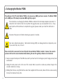
1. Exchanging the Monitor PROM
The exchange of the CPU card’s Monitor PROM is only necessary on AWS 900 Classic consoles. The Monitor PROM
on the AWS 900+ CPU already incorporates AWS Logictivity support.
The instructions on exchanging the Monitor PROM are intended for technically competent personnel. To
reduce the risk of electric shock do not perform the upgrade unless you are competent to do so. If you
would prefer an SSL technician to complete the upgrade, please contact your local SSL distributor or
office.
Disconnect the power cord before removing any panels or modules.
Take basic antistatic precautions. Electrostatic discharge (ESD) can damage electronic components, even
if you cannot feel, see, or hear it.
Please note that the console will not boot fully after the new Monitor PROM is installed. However, the console’s
processor will boot into a basic download mode allowing the new SE Logictivity software to be transferred.
1) Grasp an exposed metal part of the AWS chassis with your bare hand to discharge any static charge you may have
accumulated.
2) Unplug the mains power cord at the rear of the console. Wait 10 seconds to allow any residual charge in the
console’s electronics to decay.
3) Working from the rear, using the Pozidrive screw driver supplied with the console, remove the four screws securing
the top trim. Remove the top trim.
4
4) Using the Pozidrive screwdriver, remove the four screws securing meter panel 17-24 in position. Tilt the panel
forward slightly and lift the panel out of its slot. Lay the panel onto channels 17-24. It is not necessary to unplug
any of the meter panel’s connections.
5) On consoles shipped prior to the 3rd November 2005 (serial numbers AWS001 – 144 approximately) a screening
plate covered the AWS900’s CPU card. Remove this screening plate taking care not to drop any screws into the
console.
5
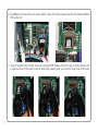
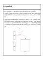
6) The AWS900’s CPU card will now be visible. With the help of the picture below locate the card’s Monitor PROM in
PCB location CD.
7) Using the supplied PLCC IC puller, remove the existing PROM. Squeeze the tool to align its hooks with the slots
in opposite corners of the socket. Insert the hooks fully, squeeze gently, and pull the IC straight out of the socket.
6
8) Note the key (angled corner) on the replacement Monitor PROM. Align the replacement PROM to match the key
on the socket. Carefully ensure correct orientation of the IC then press in place. Excessive force should not be
necessary.
9) Follow steps 3, 4 and 5 in reverse to reassemble the console.
10) Reconnect the mains power cord on switch on. The processor will now be in a download mode waiting for the
AWS900 V4 software to be transferred via MIDI. The console will not boot fully until the new software is installed.
7
2. Enabling the AWS V4 Logictivity features on your console
1) Your update kit contains two licence strings, one for Logictivity and one for V4 software, both licences must be
registered before downloading software.
2) Find the console’s serial number. The serial number label is located on the rear of the console adjacent to the mains
power inlet connector. The serial number starts with the letters AWS followed by a three digit number. Make a note
of the number for the registration process (e.g. if the serial number is AWS293, note 293).
3) If you have not registered your console on-line (or you have forgotten your username), complete the on-line
registration:
http://update.solid-state-logic.com/update/public/newuser.jsp
4) Navigate to the on-line update page:
http://update.solid-state-logic.com/update/public/
Select the ‘Activate logictivity’ option. Enter your login details and when prompted, enter your Logictivity activation
code and the numerical element of your console’s serial number previously noted.
5) Return to the on-line update page, select the ‘Activate V4’ option. When prompted, enter your V4 activation code
and the numerical element of your console’s serial number previously noted.
Note: The activation code can only be used once. Please ensure that you enter the correct serial number.
8
3. Installing the V4 software update
1) After successfully activating both licences follow the link below and download the software .jar file, the release
notes and either the Macintosh or Windows support files, as required. The software is packaged as a 3MB
(approximately) Java archive file. The file format is compatible with both PC and Macintosh (OS X only) platforms.
http://update.solid-state-logic.com/update/public/downloadrelease.jsp
2) Check that your host computer has the correct version of Java installed.
PC users: Ensure that you have the latest version of Java installed (this can be downloaded from
http://www.java.com).
Mac users: Java is included with OSX. Run your OSX Software Update to ensure that Java version 5 or above is
installed on your Mac. You will also need a Java Library Extension which can be downloaded from
http://www.mandolane.co.uk.
For Intel based Mac download Mandolane MIDI SPI. Open the downloaded zip file and drag the
libMandoMidiJNILib.jar and libMandoMidiJNILib.jnilib files to your /Library/Java/Extensions folder.
Please note that Mandolane make a small charge for the library extension.
For Power PC based machines download Plumstone. Open the downloaded zip file and drag the plumstoneserv.jar
file to your /Library/Java/Extensions folder.
You may be warned that the file cannot be moved because extensions cannot be modified. In this case click on
“Authenticate” and enter your Mac OSX admin password.
3) Ensure that your AWS is powered and connected to the MIDI port on your workstation. Close all current applications
on your workstation.
9
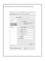
4) Double click on the AWS Software Update file. You should see the SSL AWS Software Update window appear.
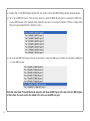
5) Go to the In MIDI Port menu. From the drop down list, select the MIDI IN port which is connected to MIDI port 1
on your AWS console. In the example shown below this was port 1 on an 8 port interface. If the list is empty, check
that you have installed the files detailed in step 2.
6) Go to the Out MIDI Port menu. From the drop down list, select the MIDI out port which is connected to MIDI port
1 on your AWS console.
Note that some Power PC based Macintosh computers will show all MIDI Inputs at the top of the list, MIDI Outputs
at the bottom. You must scroll to the middle of the list to see the MIDI out ports.
10
7) Click on the ‘Test’ button. This will transmit a packet of data to the AWS console which then in turn should return
an acknowledge packet back to the computer. If the test was successful the message 'Comms test passed, now
use send' will be displayed. If the test fails you should check that the correct MIDI port has been selected and
repeat the test.
8) Once you have established a valid connection click on the ‘Send’ button. The new code will now be transferred
to memory on the CPU card. This process will take approximately 40 minutes due to the slow data transfer rate
of MIDI and the error checking of each packet transmitted. A progress bar and transfer counter will be displayed
on screen to enable you to observe the transfer progress.
Note: Disable any power management features on your computer which may cause the computer to suspend
operation and abort the transfer.
11
9) Once the code has been successfully transferred click on the ‘Save’ button to store the new software – this takes
approximately 60 seconds. A progress bar allows you to observe the saving process. During this time it is important
that power to AWS is not interrupted. To enable new software to be written into flash memory AWS must first erase
the current software. If this process is interrupted by a power failure the AWS will be left with no valid software.
In this state AWS will be unable to re-boot. Should this happen the AWS CPU will default to a MIDI download state
and you will have to repeat the download process.
10) Once the software has been saved a ‘Please Re-Power Your Console’ message will appear.
11) Switch power off, wait 10 seconds, and then reapply power to reboot your console.
12
4. Support software installation (Macintosh)
AWS Remote
Mount the AWS924-948Remote.dmg disk image and open it. Drag the enclosed AWS Remote application to the
Applications folder, then to the Dock or any other convenient location.
ipMIDI
Mount the ipMIDI.dmg disk image and open it. Double click on the ipMIDI.pkg file to run the installation program.
Note that you will be asked to log out and in again once you have completed the installation. Once you have
logged back in open Audio MIDI Setup and double click on the ipMIDI icon. Set the number of MIDI ports to 12 in
the resulting pop-up.
If you are upgrading an older copy of ipMIDI you must uninstall it before running the installer. To uninstall ipMIDI
simply delete:
/Library/Audio/MIDI Drivers/ipMIDIDriver.bundle
You should empty the Trash after deleting the .bundle file before running the installer.
System Requirements for your workstation computer:
AWS Remote is a Java application. It will run under Java Version 5 or higher.
ipMIDI is compatible with Macintosh OS X 10.4.x tiger / 10.5.x leopard / 10.6.x snow leopard (universal binary)
13
5. Support software installation (PC)
AWS Remote
Open the Windows support files package and copy the AWS924-928Remote.exe file to the Program Files folder (or
any other convenient location) then create a shortcut to it on your desktop and/or task bar. Double clicking on this
will launch the AWS Remote program.
ipMIDI
Run the setupipmidi_1.8.exe application (note that the last part of the name may change depending on the version
you are installing) by double clicking on it. Note that you will have to restart the computer at the end of the setup
process. Once the computer has restarted right click on the ipMIDI icon in the task bar and set the number of MIDI
ports to 12 in the resulting pop-up.
If you are upgrading an older copy of ipMIDI you must uninstall it (using Add/Remove programs) before running
the installer.
System Requirements for your workstation computer:
AWS Remote is a Java application. It will run under Java Version 5 or higher.
ipMIDI is compatible with Windows 2000 (maximum 9 MIDI ports), XP and Vista.
14
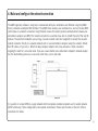
6. Make and configure the network connection
The AWS Logictivity software is designed to communicate with your workstation over Ethernet using the ipMIDI
driver to emulate a multiport MIDI interface. The ipMIDI driver enables your workstation to send and receive MIDI
control data via a network connection. Using Ethernet ensures the fastest possible communication between your
workstation computer and AWS. This network connection is essential if you wish to benefit from all of the new SE
features. The standard installation uses an RJ45 crossover network cable (not supplied) to connect the console’s
network connector directly to a separate network port on your workstation computer using the console’s default
fixed IP address of 192.168.1.2. Note that many computer adaptor cards may autosense a direct connection
negating the need for a crossover cable. If you are unsure whether your workstation computer’s network adapter
has this functionality, please use a crossover rather than a pin to pin cable.
It is possible to connect AWS to a larger network which incorporates multiple computers and to enable dynamic
(DHCP) addressing. These configurations need special consideration. Please see the notes at the end of these
instructions for details.
15
7. Direct network configuration (Macintosh)
Please note that currently OS X does not allow two ports to be used for IP traffic. As such, the connection to your
main network will not be available while the AWS is connected.
To simplify the process of switching between networks, it is recommended that you create a new network Location
for the AWS900 in network preferences. Another Location ('Internet', for example) could be created to enable
connection to the internet. This would use the network settings provided by your Internet Service Provider or
network administrator. You can easily switch between network Locations by going to the Apple Menu and scrolling
down to Location.
Using an RJ45 cable, make a direct network connection between the network port on your AWS to a network port
on your workstation computer and check that the IP address is set to FIXED in the console's SSL/MISC/NET menu.
Open System Preferences and click on Network. Create a new location by clicking where it says Location, scroll
down to Edit Locations and click the '+' sign. Name the new location AWS900.
16
Next select the Ethernet port which is connected to the AWS and configure as shown below:
17
If your Macintosh features multiple network ports, you should set the priority of these so that the Ethernet port
connected to your AWS is at the top of the list. To do this, choose Set Service Order from the Actions pop-up
menu:
18
Now drag the port connected to the AWS to the top of the list (in our example this port is Ethernet 2):
Now click OK, then Apply.
Alternatively, if you have already created a separate Location for your existing network you can simply delete the
unused ports (Airport, Firewire) from the AWS900 Location so that only the network port connected to AWS is
remaining.
19
8. Direct network configuration (PC)
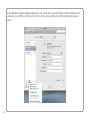
Double click on Network Connections in Start/Control Panel. Right click on the network adapter connected to your
AWS (likely to be called "Local Area Connection"). Select Properties.
Select Internet Protocol (TCP/IP) and Properties.
20
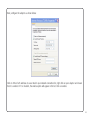
Next, configure the adapter as shown below:
Click on OK on both windows to save. Back in your network connection list, right click on your adaptor and ensure
that it is enabled. If it is disabled, the enable option will appear in the list. Click on enable.
21
9. Enabling ipMIDI on your AWS
In the SSL/MISC/SETUP menu, toggle the ’MIDI Connects Via’ setting to ‘Network’. Your console will now
communicate with your workstation via Ethernet. With ’MIDI Connects Via’ set to ‘MIDI Ports’, AWS will
communicate with your workstation via the conventional MIDI connectors on the rear of your console.
Also in the SSL/MISC/SETUP menu, ensure that the ‘DAW1’ option (workstation layer 1) and DAW2 (workstation
layer 2) are set to match your workstation or workstations if you are using the second layer. Please note that you
may need to restart the console after making a change to the DAW layer options.
22
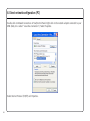
10. Finding the console using the AWS Remote application
Launch AWS Remote on your workstation. If you only have one AWS console on the network, AWS Remote will
automatically locate the console and the message ‘AWS 900 Connected’ will be shown in green text in the bottom
left hand corner of the browser:
If you have multiple AWS consoles on the network or the AWS Remote browser did not automatically locate your
console ‘No AWS 900 connected’ will be shown in red text. In this instance, click on the find icon
.
If the list is empty, click on find AWS900, select the console you wish to connect to and click on select.
If your console does not appear in the list, it suggests you have a network related issue. Please follow the steps
in the network trouble shooting section at the end of this document to resolve the issue.
23
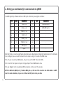
11. Setting you workstation(s) to communicate via ipMIDI
The AWS Logictivity software enables 12 MIDI ports which are pre-assigned as follows:
P or t
Layer
Assignment
Port
Layer
Assignment
1
1
Faders 1-8
9
-
AWS MIDI port 1
2
1
Faders 9-16
10
-
AWS MIDI port 2
3
1
Faders 17-24
11
-
-
4
2
Faders 1-8
12
-
-
5
2
Faders 9-16
13
-
-
6
2
Faders 17-24
14
-
-
7
-
MTC Input
15
-
-
8
-
SysEx
16
-
-
Note that there are now two switchable workstation layers allowing two independent workstations to be interfaced.
Once configured, you can switch between the two layers using the console’s SSL/DAW menu.
Port 7: If your console has AWSomation, this port is used for MIDI Time Code (MTC).
Port 8: Used for the import and export of legacy SysEx TR and AWSomation data.
Port 9-10: Mapped to the conventional MIDI connectors on the rear of the console.
NOTE: In addition to ipMIDI port 7, hardware MIDI port 4 on the rear of the console is also hard coded as an MTC
input. To avoid contention, only use one of these two MTC ports at any one time.
24
To enable control of your workstation via HUI or MCU your workstation(s) must be configured to match the
appropriate layer in the list above. This is done using the MIDI Controller configuration page of your workstation.
Below are two examples using Pro Tools 9 and Logic Pro 9:
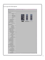
Pro Tools 9
In the Setup menu, click on Peripherals and select the MIDI Controllers tab. Using MIDI controllers 1, 2 and 3,
select HUI as the MIDI controller Type and assign the MIDI ports for this layer’s DAW to the two MIDI controllers, as
listed in the table above. If Pro Tools has been assigned to Layer 1, the MIDI Controllers window should look like
this:
25
If you have AWSomation, set the MTC generator port in the Synchronization tab to ipMIDI port 7:
26
Also, set the MMC MIDI port in the Machine Control tab to ipMIDI port 7:
27
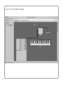
Logic Pro 9
When Logic is assigned to one of the two AWS workstation layers a Mackie Control together with a Mackie Control
Extender must be added to the Logic Pro Preferences/Control Surfaces Setup menu.
AWS Faders 1-8 are mapped to the Mackie Control ports along with the Master Fader and workstation Control
function switches. AWS Faders 9-16 and 17-24 are mapped to the Mackie Control Extender ports. The actual ipMIDI
ports used will depend on which layer (or layers) Logic is assigned to. See the list of AWS MIDI port assignments
for details. It is essential that the layout shown is followed. If the physical arrangement is reversed, then the AWS
faders will not map correctly to the on-screen faders in Logic.
If Logic is the only DAW connected to AWS, then provided that there is only one DAW layer set up with an MCU
configuration, Logic should automatically detect the three virtual controllers which will be shown in the Logic Setup
menu (as shown in fig 11.1 opposite), with the appropriate AWS ipMIDI ports assigned. If Logic fails to detect the
control surfaces, then the controllers can be added manually via the New/Install menu and the appropriate MIDI
Out port and Input assigned. Full details can be found in the online Logic Pro Control Surfaces Support guide in
the Logic Help Menu.
If AWS is set up with two MCU layers, then the automatic detection option must be disabled and the controllers
added and configured manually. Check the Disable Handshake option in SSL/MISC/SETUP is set to yes. This will
prevent Logic automatically detecting multiple Mackie Control Units.
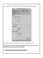
Note: Logic’s Click and Ports environment layer selects the SUM of all of the ipMIDI input ports as its default MCU
control data source. This may lead to difficulties when using multiple DAW layers. To avoid Logic responding to
MIDI messages intended for the other DAW layer, the Click and Port MIDI port mapping should be changed from
SUM to individual direct MIDI port assignment. The example in fig 11.2 shows Logic on DAW layer 1.
28
Fig 11.1 Logic control surface setup menu
29
Fig 11.2 Click and Port MIDI port mapping
30
If you have AWSomation, set the MMC midi port in File/Project Settings/Synchronisation/MIDI to ipMIDI port 7:
For other DAWs, please refer to the program’s manual for details about configuring MIDI controllers.
To find out about the new V4 features and their operation download the Owner’s guide from our website. This
document will help ensure that you get the most from the upgrade:
http://www.solidstatelogic.com/support/consoles/aws/documentation.asp
31
13. Network troubleshooting
Most Ethernet adaptor cards have two LEDs associated with each port. The first indicates that the link is connected
and the second indicates network traffic. Please note that some Macintosh computers do not have external LEDs to
indicate status. Instead the link status is shown in the System Preferences/Network menu.
On your host workstation computer, confirm that the link LED is permanently illuminated. If it is not permanently
illuminated, it suggests you have a cabling error. In this instance please check the following:
• The RJ45 network connector on the console and on your workstation are fully inserted
• If you are using a pin to pin cable to make a direct connection between your console and workstation, try replacing
your cable with an RJ45 crossover cable
• Try replacing the network cable
• If you are not using a direct connection between your console and workstation using the default fixed IP address
on the console, please try this simple configuration to rule out issues with external routers and network switches
• If the link LED is illuminated, the next step is to confirm that the activity LED is illuminating periodically to show
network traffic. If it does not illuminate periodically check the following:
• If your workstation is not connected directly to your console using a crossover RJ45 cable and fixed IP addressing,
follow the installation instructions for a simple network configuration to rule out issues with any external routers
or network switches.
32
• Using the fixed default IP address on the console, check that the workstation has basic communications using
‘ping’.
On Windows: Select Run under the Start menu. In the resulting window enter cmd to launch the command
prompt. In the command prompt window enter ping 192.168.1.2
On OSX: Open a Finder window, select Applications, then Utilities, and double-click on Terminal. In the terminal
window enter ping –c4 192.168.1.2
In both cases your host computer will try to establish communications with your console. In the resultant terminal
text, check that the console responded to every message sent by your workstation.
33
14. Larger networks
To ensure minimum latency the ipMIDI driver uses multicast UDP rather than TCP/IP. This means that:
• The network connection should be as short as possible and should only use routers that can support high data
transfer rates. Problems have been experienced with some domestic routers, particularly when used with Pro
Tools.
• Messages between the DAW computer and the AWS900+ will be received by all other devices on the network,
potentially causing problems in installations with more than one console or DAW computer. The UDP packets can
be blocked by using a network switch which allows static multicast groups to be specified. The Netgear GS108T
16 port switch is a cost effective solution which can easily be configured to allow ipMIDI traffic only to specified
ports.
34
Configure the switch in the static multicast groups page to forward packets with a multicast mac address of 01-005E- 00-00-25 to only the ports which the AWS900+ and the DAW computer are connected to. For the Netgear
GS108T, the configuration looks like this:
In this configuration, ipMidi data will only be passed to ports 1 and 2. This is where the AWS900+ and the DAW
computer would be connected. Network traffic through the rest of the ports is unaffected. If you have more than
one console on the network, create a separate VLAN for each console and associated DAW computer(s) to connect
to and add those ports to the same multicast group rule.
35
15. Assigning the AWS IP address
By default, AWS uses a fixed IP address of 192.168.1.2. Dynamic (DHCP) address allocation can be selected via the
SSL/NET menu. The currently assigned address is also shown in the SSL/NET menu. If your AWS is connected to the
computer via a network switch or router which contains a DHCP server, it should be assigned a DHCP IP address;
otherwise the fixed option should be used. Once you have altered the IP mode, you need to restart your AWS for
the change to take effect. A software restart option is available in the SSL/SETUP menu.
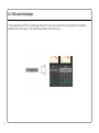
An alternative fixed IP address can be set using the console diagnostic port. This should not be necessary in most
installations. You will need a PC or Mac running terminal emulator software. Connect your computers serial port to
the rear of the console using a 9 way ‘D’ type extension cable. The pin out for the console’s 9 way ‘D’ type serial
connector is shown below:
36
P in
Description
1
Carrier (Linked to 0V)
2
TX
3
RX
4
DTR (Linked to DSR)
5
0V
6
DSR (Linked to DTR)
7
RTS (Linked to CTS)
8
CTS (Linked to RTS)
9
RI (Linked to 0V)
Set the terminal as follows: Baud rate 19200, 8 data bits, No parity, No start bit, 1 stop bit, Flow control Xon/Xoff
Press the ‘Return’ key (<CR>) and the terminal window should echo a ‘>’ if communication is established. To fix the
IP address type the following:
ip <CR>
setip nnn nnn nnn nnn <CR> where ‘nnn...’ is the IP address, e.g. ‘10 1 1 1 10’.
setmask nnn nnn nnn nnn <CR> where ‘nnn...’ is the subnet mask, e.g. ‘255 255 255 0’.
Note that this should match other devices local to the console.
setgate nnn nnn nnn nnn <CR> where ‘nnn...’ is the gateway address e.g. ‘10 1 1 1’
37
16. SSL Logictivity badge
In the upgrade kit you’ll find a small badge designed to show your console has been upgraded for Logictivity.
Carefully attach this badge to the meter-bridge location illustrated below.
38
17. Software licence agreement
Software Licence Agreement: Solid State Logic (‘SSL’) is willing to license this AWS software and accompanying documentation for this product
(the ‘Software’) to the customer (the entity that purchased the product and software) on the condition that you read and accept all of the terms
in this agreement. Please read the terms below carefully. By continuing to install the software and using the enclosed information to license the
softwareyou acknowledge that you have read and understood the agreement and agree to be bound by its terms and conditions. If you do not
agree to these terms then do not open this package, discontinue the installation process and contact your local SSL representative for advice.
Licence: SSL hereby grants you a non-exclusive licence to install and use the Software in machine-readable form on a single console. You may
copy the software only for backup purposes, provided that you reproduce all copyright and other proprietary notices that are on the original
copy of the Software.
Restrictions: SSL retains the right, title and interest in and to the Software, and any rights not granted to you herein are reserved by SSL. You
may not reverse engineer, disassemble, decompile, or translate the Software, or otherwise attempt to derive the source code for the Software,
except to the extent allowed under applicable law. If applicable law permits such activities, any information so discovered must be promptly
disclosed to SSL and shall be deemed to be the confidential proprietary information of SSL. Any attempt to transfer any of the rights, duties or
obligations hereunder is void. You may not rent, lease, loan or resell for profit the Software, or any part thereof. You may not reproduce,
distribute or create derivative works of the Software.
Limitation of Liability: In no event will SSL or it’s suppliers be liable for profits or other consequential, incidental or special damages however
arising, including negligence, in connection with the software or this agreement, even if SSL has been advised of the possibility of such
damages. In no event will SSL’s liability in connection with the Software, regardless of the form of action, exceed £100.
Indemnity: You agree to defend and indemnify SSL against all claims, losses, liabilities, damages costs and expenses, including legal fees,
which SSL may incur in connection with your breach of this Agreement.
General: The Software is a commercial item. This Agreement is governed and interpreted in accordance with the laws of the United Kingdom.
39
This equipment has been tested and found to comply with the limits for a Class B digital device, pursuant to part 15 of the FCC Rules.
These limits are designed to provide reasonable protection against harmful interference in a residential installation. This equipment
generates, uses and can radiate radio frequency energy and, if not installed and used in accordance with the instructions, may cause
FOR HOME OR OFFICE USE
harmful interference to radio communications. However, there is no guarantee that interference will not occur in a particular installation.
If this equipment does cause harmful interference to radio or television reception, which can be determined by turning the equipment off and on, the user is encouraged
to try to correct the interference by one or more of the following measures:
• Reorient or relocate the receiving antenna.
• Increase the separation between the equipment and receiver.
• Connect the equipment into an outlet on a circuit different from that to which the receiver is connected.
• Consult the dealer or an experienced radio/TV technician for help.
Tested To Comply
with FCC Standards
Instructions for Disposal of WEEE by Users in the European Union
The symbol shown here is on the product or on its packaging, which indicates that this product must not be disposed of with other waste. Instead, it is
the user’s responsibility to dispose of their waste equipment by handing it over to a designated collection point for recycling of waste electrical and
AAA
electronic equipment. The separate collection and recycling of your waste equipment at the time of disposal will help to conserve natural resources and
A
AA
ensure that it is recycled in a manner that protects human health and the environment. For more information about where you can drop off your waste
equipment for recycling, please contact your local city office, your household waste disposal service or where you purchased the product.
Standards Conformance
This apparatus fully conforms with the current protection requirements of the European community council directives on EMC and LVD.
Limited Warranty
Warranty claims will only be accepted if the purchased product has been used for its intended purpose. Any purchased product used for an unintended purpose will
not be eligible for warranty protection. For all warranty inquiries or claims please address your claim to the dealer that you purchased the product from – or to Solid
State Logic if the purchase was directly from Solid State Logic – within a period of two months from the date on which you detected its lack of conformity with the
terms of the warranty. Please include your original proof of purchase when initiating the claim.
• Within the EU:
Pursuant to the Solid State Logic Terms and Conditions under European consumer law the purchaser has full statutory warranty rights for
two years from the date of delivery of the product. The warranty is valid only in those Member States of the European Union (EU) who have
adopted the applicable EU law into their national legislation. The applicable national legislation governing the sale of consumer goods is
not affected by this warranty.
• Outside of the EU:
Outside of the European Union a 12 month warranty from date of purchase is applicable.
Out of Warranty Repairs
In the event of a fault arising after the warranty period has expired the unit should be returned to Solid State Logic either directly or via your local dealer. You will be
charged for the time spent on the repair (at Solid State Logic's current repair rate) plus the cost of parts and shipping. Note that no units can be accepted for repair
without prior arrangement (see below).
All Returns
• No unit will be accepted for repair by Solid State Logic unless accompanied by a valid RMA (Return Material Authorisation) number, obtainable from Solid State
Logic prior to shipping.
• All units should be shipped to Solid State Logic in suitable rigid packaging – Solid State Logic cannot be held responsible for any damage caused by shipping units
in other packaging. In such cases Solid State Logic will return the unit in a suitable box, which you will be charged for.
• Do not include the power cable, manual or any other items – Solid State Logic can not guarantee to return them to you.
40
Visit SSL at: www.solidstatelogic.com
82S6AWS024B
© Solid State Logic
All Rights reserved under International and Pan-American Copyright Conventions
AWS900, AWS900+, AWS900+ SE, Logictivity, SSL and Solid State Logic are trademarks of Solid State Logic
All other product names and trademarks are the property of their respective owners and are hereby
acknowledged
No part of this publication may be reproduced in any form or by any means, whether mechanical or electronic,
without the written permission of Solid State Logic, Oxford, OX5 1RU, England
As research and development is a continual process, Solid State Logic reserves the right to change the features
and specifications described herein without notice or obligation.
Solid State Logic cannot be held responsible for any loss or damage arising directly or indirectly from any error
or omission in this manual.
E&OE