1
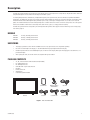
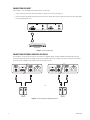
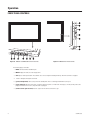
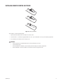
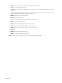
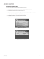
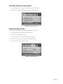
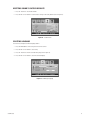
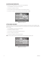
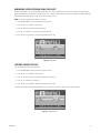
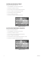
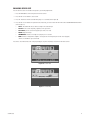
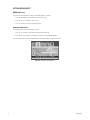
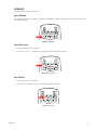
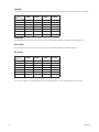
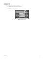
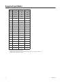
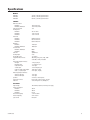
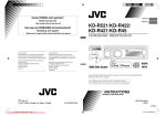
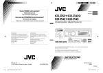
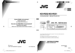
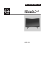
INSTALLATION/OPERATION
600 Series Flat Panel
Plasma Monitors
C2938M (12/06)
Contents
Important Safety Instructions . . . . . . . . . . . . . . . . . . . . . . . . . . . . . . . . . . . . . . . . . . . . . . . . . . . . . . . . . . . . . . . . . . . . . . . . . . . . . . . . . . . . . . . . . . . .5
Regulatory Notices . . . . . . . . . . . . . . . . . . . . . . . . . . . . . . . . . . . . . . . . . . . . . . . . . . . . . . . . . . . . . . . . . . . . . . . . . . . . . . . . . . . . . . . . . . . . . . . . . . . .6
Description . . . . . . . . . . . . . . . . . . . . . . . . . . . . . . . . . . . . . . . . . . . . . . . . . . . . . . . . . . . . . . . . . . . . . . . . . . . . . . . . . . . . . . . . . . . . . . . . . . . . . . . . . .7
Models . . . . . . . . . . . . . . . . . . . . . . . . . . . . . . . . . . . . . . . . . . . . . . . . . . . . . . . . . . . . . . . . . . . . . . . . . . . . . . . . . . . . . . . . . . . . . . . . . . . . . . . . .7
Unpacking . . . . . . . . . . . . . . . . . . . . . . . . . . . . . . . . . . . . . . . . . . . . . . . . . . . . . . . . . . . . . . . . . . . . . . . . . . . . . . . . . . . . . . . . . . . . . . . . . . . . . .7
Package Contents . . . . . . . . . . . . . . . . . . . . . . . . . . . . . . . . . . . . . . . . . . . . . . . . . . . . . . . . . . . . . . . . . . . . . . . . . . . . . . . . . . . . . . . . . . . . . . . .7
Installation . . . . . . . . . . . . . . . . . . . . . . . . . . . . . . . . . . . . . . . . . . . . . . . . . . . . . . . . . . . . . . . . . . . . . . . . . . . . . . . . . . . . . . . . . . . . . . . . . . . . . . . . . .8
Desktop Stand . . . . . . . . . . . . . . . . . . . . . . . . . . . . . . . . . . . . . . . . . . . . . . . . . . . . . . . . . . . . . . . . . . . . . . . . . . . . . . . . . . . . . . . . . . . . . . . . . . .8
Rear Panel Connectors . . . . . . . . . . . . . . . . . . . . . . . . . . . . . . . . . . . . . . . . . . . . . . . . . . . . . . . . . . . . . . . . . . . . . . . . . . . . . . . . . . . . . . . . . . . . .8
Video and Audio Connections . . . . . . . . . . . . . . . . . . . . . . . . . . . . . . . . . . . . . . . . . . . . . . . . . . . . . . . . . . . . . . . . . . . . . . . . . . . . . . . . . . . . . .10
PC Connections . . . . . . . . . . . . . . . . . . . . . . . . . . . . . . . . . . . . . . . . . . . . . . . . . . . . . . . . . . . . . . . . . . . . . . . . . . . . . . . . . . . . . . . . . . . . . . . . .13
Operation . . . . . . . . . . . . . . . . . . . . . . . . . . . . . . . . . . . . . . . . . . . . . . . . . . . . . . . . . . . . . . . . . . . . . . . . . . . . . . . . . . . . . . . . . . . . . . . . . . . . . . . . . .16
Front Panel Controls . . . . . . . . . . . . . . . . . . . . . . . . . . . . . . . . . . . . . . . . . . . . . . . . . . . . . . . . . . . . . . . . . . . . . . . . . . . . . . . . . . . . . . . . . . . . . .16
Installing Remote Control Batteries . . . . . . . . . . . . . . . . . . . . . . . . . . . . . . . . . . . . . . . . . . . . . . . . . . . . . . . . . . . . . . . . . . . . . . . . . . . . . . . . .17
Remote Control Functions . . . . . . . . . . . . . . . . . . . . . . . . . . . . . . . . . . . . . . . . . . . . . . . . . . . . . . . . . . . . . . . . . . . . . . . . . . . . . . . . . . . . . . . . .18
Basic Functions . . . . . . . . . . . . . . . . . . . . . . . . . . . . . . . . . . . . . . . . . . . . . . . . . . . . . . . . . . . . . . . . . . . . . . . . . . . . . . . . . . . . . . . . . . . . . . . . .20
Advanced Functions . . . . . . . . . . . . . . . . . . . . . . . . . . . . . . . . . . . . . . . . . . . . . . . . . . . . . . . . . . . . . . . . . . . . . . . . . . . . . . . . . . . . . . . . . . . . . .21
Information . . . . . . . . . . . . . . . . . . . . . . . . . . . . . . . . . . . . . . . . . . . . . . . . . . . . . . . . . . . . . . . . . . . . . . . . . . . . . . . . . . . . . . . . . . . . . . . . . . . . .31
Maintenance . . . . . . . . . . . . . . . . . . . . . . . . . . . . . . . . . . . . . . . . . . . . . . . . . . . . . . . . . . . . . . . . . . . . . . . . . . . . . . . . . . . . . . . . . . . . . . . . . . . . . . . .32
Cleaning . . . . . . . . . . . . . . . . . . . . . . . . . . . . . . . . . . . . . . . . . . . . . . . . . . . . . . . . . . . . . . . . . . . . . . . . . . . . . . . . . . . . . . . . . . . . . . . . . . . . . . .32
Troubleshooting . . . . . . . . . . . . . . . . . . . . . . . . . . . . . . . . . . . . . . . . . . . . . . . . . . . . . . . . . . . . . . . . . . . . . . . . . . . . . . . . . . . . . . . . . . . . . . . . .32
Supported Input Modes . . . . . . . . . . . . . . . . . . . . . . . . . . . . . . . . . . . . . . . . . . . . . . . . . . . . . . . . . . . . . . . . . . . . . . . . . . . . . . . . . . . . . . . . . . . . . . .34
Specifications . . . . . . . . . . . . . . . . . . . . . . . . . . . . . . . . . . . . . . . . . . . . . . . . . . . . . . . . . . . . . . . . . . . . . . . . . . . . . . . . . . . . . . . . . . . . . . . . . . . . . . .35
Index . . . . . . . . . . . . . . . . . . . . . . . . . . . . . . . . . . . . . . . . . . . . . . . . . . . . . . . . . . . . . . . . . . . . . . . . . . . . . . . . . . . . . . . . . . . . . . . . . . . . . . . . . . . . . .37
C2938M (12/06)
3
List of Illustrations
1
2
3
4
5
6
7
8
9
10
11
12
13
14
15
16
17
18
19
20
21
22
23
24
25
26
27
28
29
30
31
32
33
34
35
36
4
Parts List Illustration. . . . . . . . . . . . . . . . . . . . . . . . . . . . . . . . . . . . . . . . . . . . . . . . . . . . . . . . . . . . . . . . . . . . . . . . . . . . . . . . . . . . . . . . . . . . . . .7
Rear Panel Connectors . . . . . . . . . . . . . . . . . . . . . . . . . . . . . . . . . . . . . . . . . . . . . . . . . . . . . . . . . . . . . . . . . . . . . . . . . . . . . . . . . . . . . . . . . . . . .8
Connecting S-Video Input . . . . . . . . . . . . . . . . . . . . . . . . . . . . . . . . . . . . . . . . . . . . . . . . . . . . . . . . . . . . . . . . . . . . . . . . . . . . . . . . . . . . . . . . . .10
Connecting Component Video Input . . . . . . . . . . . . . . . . . . . . . . . . . . . . . . . . . . . . . . . . . . . . . . . . . . . . . . . . . . . . . . . . . . . . . . . . . . . . . . . . . .10
Connecting Video Input. . . . . . . . . . . . . . . . . . . . . . . . . . . . . . . . . . . . . . . . . . . . . . . . . . . . . . . . . . . . . . . . . . . . . . . . . . . . . . . . . . . . . . . . . . . .11
Connecting Monitor Output . . . . . . . . . . . . . . . . . . . . . . . . . . . . . . . . . . . . . . . . . . . . . . . . . . . . . . . . . . . . . . . . . . . . . . . . . . . . . . . . . . . . . . . .11
Connecting DVI Input . . . . . . . . . . . . . . . . . . . . . . . . . . . . . . . . . . . . . . . . . . . . . . . . . . . . . . . . . . . . . . . . . . . . . . . . . . . . . . . . . . . . . . . . . . . . .12
Connecting External Amplified Speakers . . . . . . . . . . . . . . . . . . . . . . . . . . . . . . . . . . . . . . . . . . . . . . . . . . . . . . . . . . . . . . . . . . . . . . . . . . . . . .12
PC Connections for VGA or DVI . . . . . . . . . . . . . . . . . . . . . . . . . . . . . . . . . . . . . . . . . . . . . . . . . . . . . . . . . . . . . . . . . . . . . . . . . . . . . . . . . . . . .13
Display Properties Dialog Box . . . . . . . . . . . . . . . . . . . . . . . . . . . . . . . . . . . . . . . . . . . . . . . . . . . . . . . . . . . . . . . . . . . . . . . . . . . . . . . . . . . . . .14
Settings Screen. . . . . . . . . . . . . . . . . . . . . . . . . . . . . . . . . . . . . . . . . . . . . . . . . . . . . . . . . . . . . . . . . . . . . . . . . . . . . . . . . . . . . . . . . . . . . . . . . .14
Plug and Play Screen . . . . . . . . . . . . . . . . . . . . . . . . . . . . . . . . . . . . . . . . . . . . . . . . . . . . . . . . . . . . . . . . . . . . . . . . . . . . . . . . . . . . . . . . . . . . .15
PMCP42 and PMCP50 Front Panel Controls . . . . . . . . . . . . . . . . . . . . . . . . . . . . . . . . . . . . . . . . . . . . . . . . . . . . . . . . . . . . . . . . . . . . . . . . . . . .16
PMCP60 Front Panel Controls. . . . . . . . . . . . . . . . . . . . . . . . . . . . . . . . . . . . . . . . . . . . . . . . . . . . . . . . . . . . . . . . . . . . . . . . . . . . . . . . . . . . . . .16
Battery Installation . . . . . . . . . . . . . . . . . . . . . . . . . . . . . . . . . . . . . . . . . . . . . . . . . . . . . . . . . . . . . . . . . . . . . . . . . . . . . . . . . . . . . . . . . . . . . . .17
Remote Control Functions. . . . . . . . . . . . . . . . . . . . . . . . . . . . . . . . . . . . . . . . . . . . . . . . . . . . . . . . . . . . . . . . . . . . . . . . . . . . . . . . . . . . . . . . . .18
Main Input Menu . . . . . . . . . . . . . . . . . . . . . . . . . . . . . . . . . . . . . . . . . . . . . . . . . . . . . . . . . . . . . . . . . . . . . . . . . . . . . . . . . . . . . . . . . . . . . . . .20
Picture Adjustment . . . . . . . . . . . . . . . . . . . . . . . . . . . . . . . . . . . . . . . . . . . . . . . . . . . . . . . . . . . . . . . . . . . . . . . . . . . . . . . . . . . . . . . . . . . . . . .21
Optimal Picture Adjustment . . . . . . . . . . . . . . . . . . . . . . . . . . . . . . . . . . . . . . . . . . . . . . . . . . . . . . . . . . . . . . . . . . . . . . . . . . . . . . . . . . . . . . . .21
Factory Default Reset . . . . . . . . . . . . . . . . . . . . . . . . . . . . . . . . . . . . . . . . . . . . . . . . . . . . . . . . . . . . . . . . . . . . . . . . . . . . . . . . . . . . . . . . . . . . .22
Sound Adjustment . . . . . . . . . . . . . . . . . . . . . . . . . . . . . . . . . . . . . . . . . . . . . . . . . . . . . . . . . . . . . . . . . . . . . . . . . . . . . . . . . . . . . . . . . . . . . . .22
Sound Defaults . . . . . . . . . . . . . . . . . . . . . . . . . . . . . . . . . . . . . . . . . . . . . . . . . . . . . . . . . . . . . . . . . . . . . . . . . . . . . . . . . . . . . . . . . . . . . . . . . .23
Selecting Language . . . . . . . . . . . . . . . . . . . . . . . . . . . . . . . . . . . . . . . . . . . . . . . . . . . . . . . . . . . . . . . . . . . . . . . . . . . . . . . . . . . . . . . . . . . . . .23
Color Temperature . . . . . . . . . . . . . . . . . . . . . . . . . . . . . . . . . . . . . . . . . . . . . . . . . . . . . . . . . . . . . . . . . . . . . . . . . . . . . . . . . . . . . . . . . . . . . . .24
Power Save Mode. . . . . . . . . . . . . . . . . . . . . . . . . . . . . . . . . . . . . . . . . . . . . . . . . . . . . . . . . . . . . . . . . . . . . . . . . . . . . . . . . . . . . . . . . . . . . . . .24
Pixel Shift . . . . . . . . . . . . . . . . . . . . . . . . . . . . . . . . . . . . . . . . . . . . . . . . . . . . . . . . . . . . . . . . . . . . . . . . . . . . . . . . . . . . . . . . . . . . . . . . . . . . . .25
Freeze Picture . . . . . . . . . . . . . . . . . . . . . . . . . . . . . . . . . . . . . . . . . . . . . . . . . . . . . . . . . . . . . . . . . . . . . . . . . . . . . . . . . . . . . . . . . . . . . . . . . . .25
Display Timeout . . . . . . . . . . . . . . . . . . . . . . . . . . . . . . . . . . . . . . . . . . . . . . . . . . . . . . . . . . . . . . . . . . . . . . . . . . . . . . . . . . . . . . . . . . . . . . . . .26
Transparency . . . . . . . . . . . . . . . . . . . . . . . . . . . . . . . . . . . . . . . . . . . . . . . . . . . . . . . . . . . . . . . . . . . . . . . . . . . . . . . . . . . . . . . . . . . . . . . . . . . .26
Screen Size . . . . . . . . . . . . . . . . . . . . . . . . . . . . . . . . . . . . . . . . . . . . . . . . . . . . . . . . . . . . . . . . . . . . . . . . . . . . . . . . . . . . . . . . . . . . . . . . . . . . .27
Size Setting. . . . . . . . . . . . . . . . . . . . . . . . . . . . . . . . . . . . . . . . . . . . . . . . . . . . . . . . . . . . . . . . . . . . . . . . . . . . . . . . . . . . . . . . . . . . . . . . . . . . .27
Automatic PC Adjustment. . . . . . . . . . . . . . . . . . . . . . . . . . . . . . . . . . . . . . . . . . . . . . . . . . . . . . . . . . . . . . . . . . . . . . . . . . . . . . . . . . . . . . . . . .28
PIP Mode. . . . . . . . . . . . . . . . . . . . . . . . . . . . . . . . . . . . . . . . . . . . . . . . . . . . . . . . . . . . . . . . . . . . . . . . . . . . . . . . . . . . . . . . . . . . . . . . . . . . . . .29
PIP Location. . . . . . . . . . . . . . . . . . . . . . . . . . . . . . . . . . . . . . . . . . . . . . . . . . . . . . . . . . . . . . . . . . . . . . . . . . . . . . . . . . . . . . . . . . . . . . . . . . . . .29
PIP Size . . . . . . . . . . . . . . . . . . . . . . . . . . . . . . . . . . . . . . . . . . . . . . . . . . . . . . . . . . . . . . . . . . . . . . . . . . . . . . . . . . . . . . . . . . . . . . . . . . . . . . . .29
Information Screen . . . . . . . . . . . . . . . . . . . . . . . . . . . . . . . . . . . . . . . . . . . . . . . . . . . . . . . . . . . . . . . . . . . . . . . . . . . . . . . . . . . . . . . . . . . . . . .31
C2938M (12/06)
Important Safety Instructions
1. Read these instructions.
2. Keep these instructions.
3. Heed all warnings.
4. Follow all instructions.
5. Do not use this apparatus near water.
6. Clean only with dry cloth.
7. Do not block any ventilation openings. Install in accordance with the manufacturer’s instructions.
8. Do not install near any heat sources such as radiators, heat registers, stoves, or other apparatus (including amplifiers) that produce heat.
9. Do not defeat the safety purpose of the polarized or grounding-type plug. A polarized plug has two blades with one blade wider than the
other. A grounding plug has two blades and a third grounding prong. The wide blade or the third prong are provided for your safety. If the
provided plug does not fit into your outlet, consult an electrician for replacement of the obsolete outlet.
10. Protect the power cord from being walked on or pinched particularly at plugs, convenience receptacles, and the points where they exit from
the apparatus.
11. Only use attachments/accessories specified by the manufacturer.
12. Only use with the cart, stand, tripod, bracket, or table specified by the manufacturer, or sold with the apparatus. When a cart is used, use
caution when moving the cart/apparatus combination to avoid injury from tip-over.
13. Refer all servicing to qualified service personnel. Servicing is required when the apparatus has been damaged in any way, such as powersupply cord or plug is damaged, liquid has been spilled or objects have fallen into the apparatus, the apparatus has been exposed to rain or
moisture, does not operate normally, or has been dropped.
14. Unplug the apparatus during lightning storms or when unused for long periods of time.
15. Apparatus shall not be exposed to dripping or splashing and no objects filled with liquids, such as vases shall be placed on the apparatus.
16. WARNING: To reduce the risk of fire or electric shock, do not expose this apparatus to rain or moisture.
17. Installation should be done only by qualified personnel and conform to all local codes.
18. Unless this unit is specifically marked as NEMA Type 3, 3R, 3S, 4, 4X, 6, or 6P enclosure, it is designed for indoor use only and it must not
be installed where exposed to rain and moisture.
19. Only use installation methods and materials capable of supporting four times the maximum specified load.
20. Only use replacement parts recommended by Pelco.
21. Avoid touching the screen directly with your fingers as the oils from your skin may be difficult to remove from the screen.
22. Do not apply direct pressure on the screen.
23. Keep the monitor in a dust-free environment and away from strong electromagnetic fields.
24. Do not use attachments, such as mounts, that are not recommended by Pelco. They may be hazardous.
25. Do not place the monitor on an unstable stand, bracket, or mount. The unit may fall, causing serious damage to the unit or injury to a
person. Only use mounts recommended by Pelco.
26. A CCC-approved power cord must be used to power this equipment when used in China.
27. A still image displayed too long may cause permanent damage to the plasma panel. Watching the monitor in 4:3 format for a long time may
leave traces of borders displayed on the left, right and center of the screen caused by the difference of light emission on the screen. Using
a camera or a system may cause a similar effect to the screen. Damages caused by this effect are not covered by the warranty.
The product and/or manual may bear the following marks:
This symbol indicates that dangerous voltage constituting a risk of electric shock is present
within this unit.
This symbol indicates that there are important operating and maintenance instructions in
the literature accompanying this unit
C2938M (12/06)
CAUTION:
RISK OF ELECTRIC SHOCK.
DO NOT OPEN.
5
Regulatory Notices
This device complies with Part 15 of the FCC Rules. Operation is subject to the following two conditions: (1) this device may not cause harmful
interference, and (2) this device must accept any interference received, including interference that may cause undesired operation.
RADIO AND TELEVISION INTERFERENCE
This equipment has been tested and found to comply with the limits of a Class A digital device, pursuant to Part 15 of the FCC Rules. These limits
are designed to provide reasonable protection against harmful interference when the equipment is operated in a commercial environment. This
equipment generates, uses, and can radiate radio frequency energy and, if not installed and used in accordance with the instruction manual, may
cause harmful interference to radio communications. Operation of this equipment in a residential area is likely to cause harmful interference in
which case the user will be required to correct the interference at his own expense.
Changes and Modifications not expressly approved by the manufacturer or registrant of this equipment can void your authority to operate this
equipment under Federal Communications Commission’s rules.
In order to maintain compliance with FCC regulations shielded cables must be used with this equipment. Operation with non-approved
equipment or unshielded cables is likely to result in interference to radio and television reception.
This Class A digital apparatus complies with Canadian ICES-003.
Cet appareil numérique de la classe A est conforme à la norme NMB-003 du Canada.
6
C2938M (12/06)
Description
The 600 Series high performance plasma monitors are designed to fit the specific needs of the security industry. The plasma monitors work well
using the VGA output of a Pelco® DVR or the DVI output of an Endura™ system.
For viewing multiple cameras simultaneously in high definition quality on the plasma monitor, Pelco recommends using PMVC4 and PMVR2
multiviewers. The PMVC4 can accept up to four composite inputs while the PMVR2 can accept up to two DVI or VGA inputs. Both models can be
mixed and matched and cascaded together (daisy chained) to put as many as 60 images of varying window sizes on the screen in clear HD
quality. This method eliminates the need of having multiple CRTs or smaller LCD monitors in racks to monitor security video. One or two plasma
monitors and a number of multiviewers can accomplish the same with less space, less energy, and more versatility.
The 600 Series plasma monitors incorporate a pixel shifting feature that optimizes the display life. Refer to Minimizing Screen Sticking Using
Pixel Shift on page 25.
MODELS
PMCP642
PMCP650
PMCP660
42-inch (1,067 mm) plasma monitor
50-inch (1,270 mm) plasma monitor
60-inch (1,524 mm) plasma monitor
UNPACKING
•
The display is packed in a carton with the standard accessories. Any optional accessories are packed separately.
•
Due to the size and weight of the display, it is recommended that two people unpack and move the display.
•
Handle the product with care to avoid breaking the glass on the front of the display. Never place the display glass face down unless it is
protected with pads.
•
After opening the carton, ensure the contents are complete and in good condition.
PACKAGE CONTENTS
1
1
1
1
1
1
2
1
42-, 50-, or 60-inch monitor with attached stand (removable)
US standard power cord
EU standard power cord
VGA cable with 15-pin D-sub connection
DVI cable
Remote control unit
AAA batteries
Installation/Operation manual
MONITOR
USER MANUAL
REMOTE CONTROL/
AAA BATTERIES
DVI CABLE
VGA CABLE
US POWER CORD
EU POWER CORD
Figure 1. Parts List Illustration
C2938M (12/06)
7
Installation
The monitor can be placed on any flat surface (desk or table), or it can be wall mounted. You can remove the desktop stand by removing the
screws that secure it to the monitor.
NOTE: Only use a recommended wall mount kit, such as the PMCP-WM, PMCP-WMT, or PMCP-WM60. To wall-mount the monitor, follow the
instructions supplied with the optional mount kit. Refer to manual C2230M for the wall mount kit instructions.
DESKTOP STAND
You can remove the desktop stand by removing the screws.
REAR PANEL CONNECTORS
NOTE: There is a slight difference in the location of external speaker jacks on the 600 Series models.
OR
Figure 2. Rear Panel Connectors
8
C2938M (12/06)
1. External Speaker Output: Line-out connections to a pair of amplified speakers or amplifier.
2. RS-232 Connector: For authorized service use.
3. DVI Input: Connection to digital video signals from a computer or any Pelco device with DVI output, especially PMVC4 and PMVR2
multiviewers.
4. RGB (VGA) Input: Connection to RGB (VGA) output of a computer or any Pelco device with VGA output, especially PMVC4 and PMVR2
multiviewers.
5. Component Video Input: Auto-detecting component video inputs (Y/Pb/Pr or Y/Cb/Cr) for connecting to the component output jacks of a
DVD player.
6. S-Video Input: Connection of S-Video signals from external sources such as VCRs or DVD players.
7. Monitor Output: Looping output from video inputs.
8. Video Input: Connection to the video and audio output of an external device, such as a matrix, switcher, camera, or DVR.
9. Video1/Video 2: Input connections from DVD players or time-lapse VCRs.
10. AC Power Connection: Connection to a 100-240 VAC, 50/60 Hz power source.
NOTES:
•
The monitors include internal speakers.
•
RGB is also referred to as VGA or PC connector in the video security market. We use the term RGB in this manual. The RGB connector is a
D-sub 15-pin female plug. RGB is analog but provides a clear, sharp picture. It can carry either standard or HDTV formats.
•
Component video input is not commonly used in the video security industry. It uses three RCA cables: red, green, and blue for better color
separation and a superior picture over composite. Component is an analog format that can carry standard and high-definition video and is
most commonly found on DVD players.
•
DVI (Digital Video Interface) provides the best picture. It is used in Pelco products such as Endura, PMVR2, PMVC4, PL outputs, DVD
players, and satellite boxes. Since the signal received and monitor are both digital, no conversion occurs to degrade the signal. Pelco
recommends using multiviewers (PMVR2, PMVC4) with the 600 Series monitors using DVI. DVI can carry either standard or HDTV formats.
C2938M (12/06)
9
VIDEO AND AUDIO CONNECTIONS
CONNECTING S-VIDEO INPUT
Refer to Figure 3. To use S-Video input, do the following:
1. Connect the external device’s S-Video (4-pin DIN) connector to the monitor’s S-VIDEO INPUT connector.
2. Connect the device’s red (R) and white (L) audio jacks to the monitor’s R and L audio-in jacks of the Video Input.
Figure 3. Connecting S-Video Input
CONNECTING COMPONENT VIDEO INPUT
Refer to Figure 4. To use component video input, do the following:
1. Connect the external device’s green jack (labeled Y) to the monitor’s green Y jack.
2. Connect the device’s red jack (labeled Pr) to the monitor’s red Pr/Cr jack.
3. Connect the device’s blue jack (labeled Pb) to the monitor’s blue Pb/Cb jack.
4. Connect the device’s red (R) and white (L) audio jacks to the monitor’s R and L audio-in jacks.
Figure 4. Connecting Component Video Input
10
C2938M (12/06)
CONNECTING VIDEO INPUT
Refer to Figure 5. To use video input, do the following:
1. Connect the external device’s jack to the monitor’s VIDEO INPUT jack.
2. Connect the device’s red (R) and white (L) audio jacks to the monitor’s R and L audio-in jacks of the Video Input.
Figure 5. Connecting Video Input
CONNECTING MONITOR OUTPUT
Refer to Figure 6. To use monitor output, do the following:
1. Connect the jack from the DVR or VCR (for recording) or audio system to the monitor’s MONITOR OUTPUT jack.
2. Connect the device’s audio jack to the monitor’s R and L audio-in jacks located next to the VIDEO connector.
DVR
Figure 6. Connecting Monitor Output
C2938M (12/06)
11
CONNECTING DVI INPUT
Refer to Figure 7. To use DVI (Digital Video Interface) input, do the following:
1. Connect the DVI-jack of the Pelco multiviewer, Endura, or computer to the monitor’s DVI input jack.
2. Connect the device’s red (R) and white (L) audio jacks to the monitor’s R and L audio-in jacks located next to the DVI connector. Audio might
be used with DVD players or PCs.
MULTIVIEWER
Figure 7. Connecting DVI Input
CONNECTING EXTERNAL AMPLIFIED SPEAKERS
Refer to Figure 8. You can connect this monitor to an external set of amplified speakers using the EXTERNAL SPEAKER OUTPUT (L/R) jacks
located on the back of the monitor. A standard size phono jack is required to plug into the L/R jacks on the monitor. These line-out connections
can also be sent to an amplifier to play through a stereo or home theater system.
OR
SPEAKERS
SPEAKERS
Figure 8. Connecting External Amplified Speakers
12
C2938M (12/06)
PC CONNECTIONS
USING RGB (VGA) OR DVI VIDEO INPUT
Refer to Figure 13.
1. Connect the PC’s 15-pin D-Sub RGB (VGA) connector to the monitor’s RGB-IN connector.
If you have a PC that is equipped with a DVI, you can connect the PC DVI connector from the PC to the monitor’s DVI-IN connector.
2. For either RGB (VGA) or DVI, connect the PC’s audio jack to the monitor’s R and L (DVI/RGB) audio-in jacks.
OR
PC
PC
Figure 9. PC Connections for VGA or DVI
CONNECT POWER
Plug the provided power cord into the AC IN connection on the back panel. Plug the other end of the cord into a power receptacle.
SETTING UP YOUR DISPLAY USING PLUG AND PLAY
This display adheres to the VESA® plug and play standard to eliminate complicated and time-consuming monitor setup. This monitor identifies
itself to the computer and automatically sends the PC its Extended Display Identification Data (EDID) using Display Data Channel (DDC) protocols.
C2938M (12/06)
13
SETTING UP YOUR PC IN WINDOWS FOR USE WITH MONITOR USING A VGA CONNECTOR
The display settings for a typical Windows®-based computer are shown below. However, the actual screen on your computer will differ
depending on the Windows version and video card in the computer. The basic setup will apply in most cases even though the actual screen may
look different from the example below.
1. Go to the Windows’ Control Panel by clicking START/SETTINGS/CONTROL PANEL. The system displays the Control Panel window.
2. Select the DISPLAY icon from this window. The system displays the Display Properties dialog box (refer to Figure 10).
Figure 10. Display Properties Dialog Box
3. Select the SETTINGS tab to display your computer’s video output settings (refer to Figure 11).
Figure 11. Settings Screen
4. Set the Screen Resolution settings to 1024 x 768 pixels. For Color Quality, select 24 Bit Color or higher (might also be expressed as
16 million colors).
14
C2938M (12/06)
5. If a vertical-frequency option is available, set the value to 60 Hz (refer to Figure 12).
Figure 12. Plug and Play Screen
6. Click OK to complete the setting.
NOTE: Both screen position and size will vary depending on the type of PC graphics card and its selected resolution.
C2938M (12/06)
15
Operation
FRONT PANEL CONTROLS
Figure 13. PMCP42 and PMCP50 Front Panel Controls
Figure 14. PMCP60 Front Panel Controls
The following apply to all models.
1. INPUT: Switches between available inputs.
2. MENU: Engages the OSD (on-screen display) menu.
3. VOL: Adjusts volume up and down. These buttons also serve as navigation and adjustment keys when the OSD menu is engaged.
4. and : Navigates through the OSD menu.
5. (power/standby button): Turns on/off power from standby mode. There is a waiting period between on/off cycles.
6. (power indicator): Indicates power status. Solid green means the power is on. Red means the display is shut off, but the power cord is
plugged in. When the LED is not lit, the power cord is unplugged.
7. (remote control signal receiver): Receives signal. Point the remote control at this spot.
16
C2938M (12/06)
INSTALLING REMOTE CONTROL BATTERIES
Figure 15. Battery Installation
Refer to Figure 15 for the following procedure.
1. Open and remove the battery cover on the back of the remote control.
2. Install two AAA size 1.5 V batteries (supplied). Match the + and – signs on the batteries to the signs on the battery compartment.
3. Close the battery cover. Make sure the lock snaps closed.
WARNING:
C2938M (12/06)
•
Dispose of batteries in a designated disposal area. Do not throw batteries into a fire.
•
Do not mix battery types.
•
Remove dead batteries immediately to prevent battery acid from leaking into the battery compartment.
•
Remove the batteries if you do not intend to use the remote control for a long period of time.
17
REMOTE CONTROL FUNCTIONS
Figure 16. Remote Control Functions
1. MUTE: Turns on/off sound.
2. POWER: Switches the monitor from standby mode to on, and back to standby mode.
3. LOCATE: Selects a location for the subpicture. Available in PIP (picture-in-picture) mode only.
4. SIZE: Selects a size for the subpicture. Available in PIP mode only.
5. SWAP: Switches the main picture and subpicture. Available in PIP and PBP modes only. (PBP is picture-by-picture, which is two images of
the same size side by side on the screen.)
18
C2938M (12/06)
6. A.SWAP: Selects audio for the main or subpicture. Available in PIP and PBP modes only.
7. SPLIT: Selects a PIP mode (NORMAL, PIP, PBP).
8. S.SELECT: Selects the main picture or subpicture. Then you can adjust the status of the selected picture. Available in PIP and PBP
modes only.
When in PIP or PBP mode, this button lets you put “focus” on either the subpicture (PIP) or the main picture. For example, select the
subpicture. Any adjustment made to the picture will affect only the PIP.
9. MENU: Activates the OSD (on-screen display) menu.
10. VOL: Adjusts the volume up or down.
11. and : Used in the selection process when navigating menus and submenus.
12. INPUT: Displays the available input sources.
13. AUTO: Auto adjusts the image with RGB and DVI if not centered correctly.
14. I.SIZE: Determines whether to display the image in wide screen, zoom, 4:3, etc.
15. FREEZE: Freezes the screen display. The playback system will continue playing.
16. (not in use)
17. RECALL: Shows the current input and sleep timer.
18. SLEEP: Turns the timer on and activates the sleep timer.
NOTE: In Figure 16, buttons on the remote control that are not identified by a callout are disabled.
C2938M (12/06)
19
BASIC FUNCTIONS
POWERING ON/OFF
Make sure the monitor is plugged into the wall outlet with the supplied power cord. The STATUS LED on the control panel will glow red.
1. Press the on/off button on the front panel or the POWER button on the remote control. The monitor will turn on after a brief pause.
The STATUS LED will turn green to indicate power is on.
2. Turn off the power by again pressing the on/off button on the front panel or the POWER button on the remote control.
SELECTING SIGNAL SOURCE
1. Press the INPUT button on the front panel or the remote control.
2. Press the or button to cycle the monitor through the available input signal sources in the following order:
VIDEO1>VIDEO2>VIDEO>S-VIDEO>COMPONENT>RGB>DVI (refer to Figure 17).
3. Press the VOL+ or VOL- button to select the source.
Figure 17. Main Input Menu
ADJUSTING/MUTING VOLUME
Adjust the volume up or down using the volume button on either the remote control or the front panel.
MUTING VOLUME USING REMOTE CONTROL
1. Press the MUTE button on the remote control to silence the audio.
2. Press the MUTE, VOL+, or VOL- button to restore the audio.
DISPLAYING INFORMATION
Press the RECALL button to display the channel information and the setting status. Press RECALL again to exit. The displayed information can
differ depending on the selected source.
20
C2938M (12/06)
ADVANCED FUNCTIONS
ADJUSTING PICTURE SETTINGS
You can make various picture adjustments by using the Picture Adjustment OSD menu.
1. Press the MENU button on the front panel or the remote control. The program displays the Image menu.
2. Press the button to enter the selected menu group (refer to Figure 18).
3. Press the button to select the option you want to adjust. The following menus appear depending on the input source:
•
•
Brightness, Contrast, Sharpness, Color, Tint, Video Defaults
Brightness, Contrast, Phase, Frequency, Sharpness (RGB [PC] mode), Video Defaults
4. Press the VOL+ or VOL- button to select the optimal setting (refer to Figure 19).
5. Press the MENU button to return to the previous menu.
Figure 18. Picture Adjustment
Figure 19. Optimal Picture Adjustment
C2938M (12/06)
21
RESETTING PICTURE TO FACTORY DEFAULTS
1. In the Image Menu, press the button to select Video Defaults (refer to Figure 20).
2. Press the VOL+ or VOL- button to reset the picture settings to the factory defaults.
Figure 20. Factory Default Reset
ADJUSTING SOUND SETTINGS
You can make various sound adjustments by using the Sound Adjustment OSD menu.
1. Press the MENU button on the front panel or the remote control.
2. Press the VOL+ or VOL- button to select Audio.
3. Press the button to enter the selected menu group (refer to Figure 21).
4. Press the or button to select the desired option: Treble>Bass>Balance.
5. Press the VOL+ or VOL- button to adjust the settings.
Figure 21. Sound Adjustment
22
C2938M (12/06)
RESETTING SOUND TO FACTORY DEFAULTS
1. Press the button to select Audio Defaults.
2. Press the VOL+ or VOL- button to reset the audio settings to the factory defaults (refer to Figure 22).
Figure 22. Sound Defaults
SELECTING LANGUAGE
The monitor has multiple OSD Menu languages built in.
1. Press the MENU button on the front panel or the remote control.
2. Press the VOL+ or VOL- button to select Setup.
3. Press the button to enter the selected menu group (refer to Figure 23).
4. Press the VOL+ or VOL- button to select the desired language.
Figure 23. Selecting Language
C2938M (12/06)
23
ADJUSTING COLOR TEMPERATURE
You can change the color temperature (Kelvin) of the entire screen to suit your requirements.
1. Press the MENU button on the front panel or the remote control.
2. Press the VOL+ or VOL- button to select Setup.
3. Press the button to enter the selected menu group. Select Color Temp (refer to Figure 24).
4. Press the VOL+ or VOL- button to select the desired option: Warm>Normal (6500K)>Cool (9300K).
Figure 24. Color Temperature
SETTING POWER SAVE MODE
The monitor has a built-in sleep timer that lets you set a time interval (10 to 180 minutes) for the monitor to turn off. (For example, a security
guard who makes rounds but is not sure how long he will be gone, can set the sleep timer to go off in 10 minutes to minimize possible burn in
and to save energy.)
1. Press the MENU button on the front panel or the remote control.
2. Press the VOL+ or VOL- button to select Setup.
3. Press the button to enter the selected menu group (refer to Figure 25).
4. Press the or button to select Sleep Timer.
5. Press the VOL+ or VOL- button to select the desired time interval.
NOTE: You can also select the desired time period by repeatedly pressing the SLEEP button on the remote control.
Figure 25. Power Save Mode
24
C2938M (12/06)
MINIMIZING SCREEN STICKING USING PIXEL SHIFT
A difference in brightness can occur around dark or bright areas. This is due to deterioration in the fluorescent substance used in the plasma
display if a fixed pattern is displayed for a long period of time; this is image sticking. A feature is built in to shift the pixels enough to reduce the
chance of burning an image onto the screen. You can turn this feature on or off.
NOTE: This feature is disabled when DVI input is selected.
1. Press the MENU button on the front panel or the remote control.
2. Press the VOL+ or VOL- button to select Screen.
3. Press the button to enter the selected menu group.
4. Press the or button to select Pixel Shift (refer to Figure 26).
5. Press the VOL+ or VOL- button to select the desired option (OFF or ON).
Figure 26. Pixel Shift
FREEZING CURRENT PICTURE
You can freeze the picture when watching video.
1. Press the MENU button on the front panel or the remote control.
2. Press the VOL+ or VOL- button to select Screen.
3. Press the button to enter the selected menu group (refer to Figure 27).
4. Press the or button to select Freeze.
5. Press the VOL+ or VOL- button to select the desired option (OFF or ON).
You can also freeze the current picture by pushing Freeze on the remote control. Press it again to return to normal viewing.
Figure 27. Freeze Picture
C2938M (12/06)
25
SELECTING ON-SCREEN DISPLAY TIMEOUT
You can choose how long the OSD will be shown.
1. Press the MENU button on the front panel or the remote control.
2. Press the VOL+ or VOL- button to select Setup.
3. Press the button to enter the selected menu group (refer to Figure 28).
4. Press the or button to select OSD Settings (5 to 20 seconds).
5. Press the VOL+ button to enter the selected menu group.
6. Press the or button to select Timeout.
7. Press the VOL+ or VOL- button until you have the desired setting.
Figure 28. Display Timeout
ADJUSTING MENU TRANSPARENCY (OPAQUENESS)
You can give the OSD transparency background.
1. Press the MENU button on the front panel or the remote control.
2. Press the VOL+ or VOL- button to select Setup.
3. Press the button to enter the selected menu group (refer to Figure 29).
4. Press the or button to select OSD Settings.
5. Press the VOL+ button to enter the selected menu group. Transparency is selected.
6. Press the VOL+ or VOL- button until you have the desired setting.
Figure 29. Transparency
26
C2938M (12/06)
CHANGING SCREEN SIZE
You can select the screen size that best corresponds to your viewing requirements.
1. Press the MENU button on the front panel or the remote control.
2. Press the VOL+ or VOL- button to select Screen.
3. Press the button to enter the selected menu group. Size is selected (refer to Figure 30).
4. Press the VOL+ or VOL- button until you have the desired setting, as follows: AUTO>FILL ALL>FILL ASPECT>ZOOM>ANAMORPHIC>WIDE*
(refer to Figure 31).
•
•
•
•
•
•
AUTO is the default and chooses the best setting for the selected input.
FILL ALL fills the screen completely, regardless of the aspect ratio.
FILL ASPECT puts the screen in the proper aspect ratio (4:3 or 16:9).
ZOOM enlarges the image.
ANAMORPHIC stretches a 4:3 image to fit properly on a 16:9 screen.
WIDE stretches an image with no regard to 16:9 aspect ratio. The image may turn off the screen (cropped).
*WIDE is not available in split screen mode.
You can also select the desired screen size by repeatedly pressing the I.SIZE (image size) button on the remote control.
Figure 30. Screen Size
Figure 31. Size Setting
C2938M (12/06)
27
SETTING UP RGB INPUT
RGB Mode Preset
You can access the RGB mode preset by pressing the INPUT button, as follows:
1. Press the MENU button on the front panel or the remote control.
2. Press the VOL+ or VOL- button to select Screen.
3. Press the button to enter the selected menu group.
Automatic Adjustment
You can adjust the PC screen automatically, as follows:
1. Press the or button to select Auto Positioning (refer to Figure 32).
2. Press the VOL+ or VOL- button. Screen quality and position are automatically adjusted.
You can also adjust the PC screen automatically by pressing the AUTO button on the remote control.
Figure 32. Automatic PC Adjustment
28
C2938M (12/06)
VIEWING PIP
You can control PIP (picture-in-picture), as follows:
Select PIP Mode
Press SPLIT on the remote control repeatedly to select the desired mode (refer to Figure 33). Available modes are displayed in the following
order: NORMAL>PIP>PBP.
Figure 33. PIP Mode
Select PIP Location
1. Press the LOCATE button (refer to Figure 34).
2. Press the VOL+, VOL-, , or button to select the desired location (available in PIP mode only).
Figure 34. PIP Location
Select PIP Size
1. Press the SIZE button (refer to Figure 35).
2. Press the VOL+ or VOL- button to select the desired size (available in PIP mode only).
Figure 35. PIP Size
C2938M (12/06)
29
Swap PIP
You can swap the main picture and PIP by pressing the SWAP button (available in PIP and PBP mode only). The two pictures are interchanged.
PIP
Sub
VIDEO 1
VIDEO 2
VIDEO
√
√
VIDEO 1
VIDEO 2
√
VIDEO
√
√
√
S-VIDEO
√
√
S-VIDEO
√
√
√
√
COMPONENT
RGB
DVI
Swap Audio
You can alternate between the main or PIP audio by pressing the A.SWAP (audio swap) button. (Available in PIP and PBP mode only.)
Select Status
You can select main or PIP to adjust their status by pressing the S.SELECT button. (Available in PIP and PBP mode only.)
PIP Settings
PIP
Sub
VIDEO 1
VIDEO 2
VIDEO
S-VIDEO
√
√
√
√
√
VIDEO 1
VIDEO 2
√
VIDEO
√
√
S-VIDEO
√
√
√
COMPONENT*
√
√
√
√
RGB*
√
√
√
√
DVI*
√
√
√
√
√
*Maximum: 480p, 576p, 1024 x 768/60Hz
In PIP mode, the subinput source is defined differently for the default value (Video 1 or Video 2) depending on your plasma model.
30
C2938M (12/06)
INFORMATION
This screen displays information about Pelco headquarters.
1. Press the MENU button on the front panel or remote control.
2. Press the VOL+ or VOL– button to select Info.
Figure 36. Information Screen
C2938M (12/06)
31
Maintenance
If the quality of the picture is poor and cannot be improved by making adjustments on the front control panel, inspect all system connections and
cable runs.
WARNING: To reduce the risk of electrical shock, do not remove the cover or back of the monitor. No user-serviceable parts are inside.
Refer servicing to qualified personnel, or contact the Pelco Customer Service Department (1-800-289-1981) for assistance. Refer to the
Product Warranty and Return Information located on the inside back cover of this manual.
CLEANING
CAUTION
Keep your hands, face, and objects away from the display’s ventilation holes. The air being released through the exhaust holes is very hot and
can cause burns. Placing an object near the top of the display may damage the object or the display itself.
CLEANING THE FRONT PANEL
•
Gently wipe your screen with a cleaning cloth or a soft, clean, lint-free cloth.
•
If the surface is especially dirty, soak a soft, clean, lint-free cloth in a mild detergent solution. Wring the cloth to remove excess liquid.
Wipe the panel to remove dirt, and then use a dry cloth of the same type to dry the panel.
•
Do not scratch the surface with hard objects or use volatile substances such as insect sprays, solvents, or thinners.
CLEANING THE CABINET
•
Clean the cabinet with a soft, clean, lint-free cloth if it becomes dirty.
•
If it becomes especially dirty, soak a soft, clean, lint-free cloth in a mild detergent solution. Wring the cloth to remove excess liquid.
Wipe the cabinet, and then use a dry cloth of the same type to dry the cabinet.
•
Do not get water or detergent on the display surface.
•
Do not place anything made of rubber or PVC near the cabinet for long periods.
TROUBLESHOOTING
NO PICTURE IS DISPLAYED
•
Possible cause: The power cord is disconnected.
Remedy: Plug in the power cord.
•
Possible cause: The selected input has no connection, or the monitor is in standby mode in RBG mode.
Remedy: Connect a known, good video source.
INTERFERENCE DISPLAYED ON THE MONITOR OR AUDIBLE NOISE IS HEARD
Possible cause: Caused by surrounding electrical appliances, cars/motorcycles or fluorescent lights.
Remedy: Move the monitor to another location to see if the interference is reduced.
COLOR IS ABNORMAL
Possible cause: The signal cable is not connected properly.
Remedy: Make sure the signal cable is attached firmly to the back of the monitor, and from the source.
32
C2938M (12/06)
PICTURE IS DISTORED WITH ABNORMAL PATTERNS
•
Possible cause: The signal cable is not connected properly.
Remedy: Make sure the signal cable is attached firmly to the back of the monitor, and from the source.
•
Possible cause: The input signal is beyond the monitor’s capabilities.
Remedy: Check the video signal source to see if it is beyond the monitor’s range. Verify the signal source’s specifications with the monitor’s
specifications.
DISPLAY IMAGE DOES NOT FILL THE SCREEN COMPLETELY
•
Possible cause: Under RGB mode, the H-Size and V-Size are set incorrectly.
Remedy: Use H-Size and V-Size to adjust the video size.
•
Possible cause: Under AV1, AV2, or Component with 480i input, the 4:3 Wide mode is switched on.
Remedy: Use the WIDE button to scroll through the various full screen modes.
SOUND BUT NO PICTURE
Possible cause: Improperly connected source signal cable.
Remedy: Make sure both video inputs and sound inputs are correctly connected.
PICTURE BUT NO SOUND
•
Possible cause: Improperly connected source signal cable.
Remedy: Make sure both video inputs and sound inputs are correctly connected.
•
Possible cause: Volume is turned all the way down.
Remedy: Use VOL +/- to hear sound.
•
Possible cause: Mute is turned on.
Remedy: Use the MUTE button to switch off mute.
C2938M (12/06)
33
Supported Input Modes
Mode
Resolution
H Freq. (kHz)
V Freq. (Hz)
0
720 x 400*
31.469
70.000
1
640 x 480
31.460
50.000
2
640 x 480
31.500
60.000
3
640 x 480
37.700
72.000
4
640 x 480
37.500
75.000
5
640 x 480
43.300
85.000
6
800 x 600
35.100
56.000
7
800 x 600
37.900
60.000
8
800 x 600
48.100
72.000
9
800 x 600
46.900
75.000
10
800 x 600
53.700
85.000
11
1024 x 768
48.400
60.000
12
1024 x 768
56.500
70.000
13
1024 x 768
60.000
75.000
14
1024 x 768
64.000
80.000
15
1024 x 768
68.300
85.000
16
1280 x 1024**
64.000
60.000
17
1366 x 768***
50.000
60.000
*PMCP660 cannot support this resolution.
**PMCP642 cannot support this resolution. PMCP660 cannot support this resolution in DVI mode.
***PMCP642 cannot support this resolution.
34
C2938M (12/06)
Specifications
MODELS
PMCP642
PMCP650
PMCP660
42-inch (1,067 mm) plasma monitor
50-inch (1,270 mm) plasma monitor
60-inch (1,524 mm) plasma monitor
GENERAL
Native Resolution
PMCP642
PMCP650, PMCP660
Panel Aspect Ratio
Viewing Area
PMCP642
PMCP650
PMCP660
Pixel Pitch
PMCP642
PMCP650
PMCP660
Brightness
PMCP642
PMCP650, PMCP660
Contrast Ratio
PMCP642, PMCP650
PMCP660
Panel Life
Viewing Angle
Displayable Colors
Supported Video Formats
PIP
Video Input/Output Interfaces
DVI Input
RGB (DVI) Input
Component Input
S-Video Input
Composite Video Input/Output
Video 1, 2 Input/Output
Audio Input/Output Interfaces
Audio for DVI Input
Audio for RGB Input
Speakers
Front Panel Controls
Indicators
1024 X 768; XGA
1366 X 768; WXGA
16:9
922 x 519 mm
1106 x 622 mm
1320 x 742 mm
0.900 x 0.676 mm
0.810 x 0.810 mm
0.966 x 0.966 mm
1200 cd/m2
1000 cd/m2
8000:1
6000:1
45,000 hours
<160°
16.7 million
480i, 480p, 576p, 576i, 720p, 1080i
Selectable, sizable, moveable
1 DVI jack, 24-pin
1 D-Sub jack, 15-pin
1 RCA jack
1 mini DIN jack, 4-pin
1 BNC jack, looping
2 RCA jacks, looping
1 RCA jack
1 RCA jack
2 internal; 2 external jacks
Power, input, volume, menu, selection
Status LED (power on/standby/off)
ELECTRICAL
Input Voltage
Power Consumption
PMCP642
PMCP650
PMCP660
Horizontal Frequency
Vertical Frequency
Sync Format
C2938M (12/06)
100-240 VAC, 50/60 Hz, internal power supply
350 W
450 W
610 W
31 kHz to 68 kHz
25 Hz to 85 Hz
NTSC/PAL
35
PHYSICAL
Dimensions (without stand)
PMCP642
PMCP650
PMCP660
Unit Weight (without stand)
PMCP642
PMCP650
PMCP660
Shipping Weight
PMCP642
PMCP650
PMCP660
4.2" D x 40.5" W x 24.6" H (10.7 x 102.8 x 62.5 cm)
4.6" D x 47.5" W x 28.4" H (11.7 x 120.7 x 72.1 cm)
3.7" D x 57.2" W x 34.5" H (9.4 x 145.4 x 87.6 cm)
66.1 lb (30.0 kg)
92.6 lb (42.0 kg)
149.9 lb (68.0 kg)
80 lb (36 kg)
108 lb (49 kg)
172 lb (78 kg)
ENVIRONMENTAL
Operating Temperature
Storage Temperature
Operating Humidity
Storage Humidity
32° to 104°F (0° to 40°C)
-4° to 140°F (-20° to 60°C)
20% to 80% noncondensing
10% to 90% noncondensing
OPTIONAL ACCESSORIES
PMCP-WM
PMCP-WMT
PMCP-WM60
Fixed wall mount for PMCP642 and PMCP650
Tilt wall mount for PMCP642 and PMCP650
Fixed wall mount for PMCP660
PMVR2
PMVC4
Multiviewer with 2 DVI and 2 VGA inputs, VGA or DVI output
Multiviewer with 4 composite inputs, VGA or DVI output
(Design and product specifications subject to change without notice.)
36
C2938M (12/06)
Index
A
A.Swap button 19
AC power connection 9
Audio swap 30
Auto button 19
Automatic adjustment 28
C
Color temperature 24
Component video input 9
Connecting component video input 10
Connecting DVI input 12
Connecting external speakers 12
Connecting monitor output 11
Connecting s-video 10
Connecting video input 11
Connections 10
D
DVI input 9
F
Freeze button 19
Freeze picture 25
Front panel 16
I
I.Size button 19
Information display 20
INPUT 16
Input button 19
Input modes 34
L
Language 23
Locate button 18
M
MENU 16
Menu button 19
Models 7
Monitor output 9
Mute button 18
Remote control receiver 16
Reset picture to factory defaults 22
Reset sound to factory defaults 23
RGB (VGA) input 9
RGB (VGA)/DVI input 13
RGB mode preset 28
RS-232 connector 9
S
S.Select button 19
Screen size adjustment 27
Screen sticking 25
Select signal 20
Selection buttons 16
Setting RGB input 28
Size button 18
Sleep button 19
Sound settings 22
Speaker output 9
Specifications 35
Split button 19
Status selection 30
S-video input 9
Swap button 18
T
Timeout displays 26
Transparency 26
Troubleshooting 32
V
Video 1/Video 2 9
Video input 9
VOL 16
Volume adjustment 20
Volume button 19
Volume mute 20
W
Windows settings 14
P
Picture settings 21
PIP location 29
PIP settings 30
PIP size 29
PIP swap 30
PIP viewing 29
Pixel shift 25
Plug and play 13
Power button 18
Power connection 13
Power indicator 16
Power on/off 20
Power save mode 24
Power/standby button 16
R
Rear panel 8
Recall button 19
Remote control batteries 17
Remote control buttons 18
C2938M (12/06)
37
PRODUCT WARRANTY AND RETURN INFORMATION
WARRANTY
Pelco will repair or replace, without charge, any merchandise proved defective in material or
workmanship for a period of one year after the date of shipment.
Exceptions to this warranty are as noted below:
• Five years on FR/FT/FS Series fiber optic products and TW3000 Series unshielded twisted
pair transmission products.
• Three years on Spectra ® IV products.
• Three years on Genex ® Series products (multiplexers, server, and keyboard).
• Three years on Camclosure ® and fixed camera models, except the CC3701H-2,
CC3701H-2X, CC3751H-2, CC3651H-2X, MC3651H-2, and MC3651H-2X camera models,
which have a five-year warranty.
• Three years on PMCL200/300/400 Series LCD monitors.
• Two years on standard motorized or fixed focal length lenses.
• Two years on Legacy ®, CM6700/CM6800/CM9700 Series matrix, and DF5/DF8 Series
fixed dome products.
• Two years on Spectra III ™, Esprit®, ExSite™, and PS20 scanners, including when used in
continuous motion applications.
• Two years on Esprit and WW5700 Series window wiper (excluding wiper blades).
• Two years (except lamp and color wheel) on Digital Light Processing (DLP ®) displays.
The lamp and color wheel will be covered for a period of 90 days. The air filter is not
covered under warranty.
• Eighteen months on DX Series digital video recorders, NVR300 Series network video
recorders, and Endura ™ Series distributed network-based video products.
• One year (except video heads) on video cassette recorders (VCRs). Video heads will be
covered for a period of six months.
• Six months on all pan and tilts, scanners or preset lenses used in continuous motion
applications (that is, preset scan, tour and auto scan modes).
Pelco will warrant all replacement parts and repairs for 90 days from the date of Pelco
shipment. All goods requiring warranty repair shall be sent freight prepaid to Pelco, Clovis,
California. Repairs made necessary by reason of misuse, alteration, normal wear, or accident
are not covered under this warranty.
Pelco assumes no risk and shall be subject to no liability for damages or loss resulting from
the specific use or application made of the Products. Pelco’s liability for any claim, whether
based on breach of contract, negligence, infringement of any rights of any party or product
liability, relating to the Products shall not exceed the price paid by the Dealer to Pelco for
such Products. In no event will Pelco be liable for any special, incidental or consequential
damages (including loss of use, loss of profit and claims of third parties) however caused,
whether by the negligence of Pelco or otherwise.
The above warranty provides the Dealer with specific legal rights. The Dealer may also have
additional rights, which are subject to variation from state to state.
If a warranty repair is required, the Dealer must contact Pelco at (800) 289-9100 or
(559) 292-1981 to obtain a Repair Authorization number (RA), and provide the following
information:
1. Model and serial number
2. Date of shipment, P.O. number, Sales Order number, or Pelco invoice number
3. Details of the defect or problem
If there is a dispute regarding the warranty of a product which does not fall under the
warranty conditions stated above, please include a written explanation with the product
when returned.
Method of return shipment shall be the same or equal to the method by which the item was
received by Pelco.
RETURNS
In order to expedite parts returned to the factory for repair or credit, please call the factory at
(800) 289-9100 or (559) 292-1981 to obtain an authorization number (CA number if returned
for credit, and RA number if returned for repair).
All merchandise returned for credit may be subject to a 20% restocking and refurbishing
charge.
Goods returned for repair or credit should be clearly identified with the assigned CA or RA
number and freight should be prepaid. Ship to the appropriate address below.
If you are located within the continental U.S., Alaska, Hawaii or Puerto Rico, send goods to:
Service Department
Pelco
3500 Pelco Way
Clovis, CA 93612-5699
If you are located outside the continental U.S., Alaska, Hawaii or Puerto Rico and are instructed
to return goods to the USA, you may do one of the following:
If the goods are to be sent by a COURIER SERVICE, send the goods to:
Pelco
3500 Pelco Way
Clovis, CA 93612-5699 USA
If the goods are to be sent by a FREIGHT FORWARDER, send the goods to:
Pelco c/o Expeditors
473 Eccles Avenue
South San Francisco, CA 94080 USA
Phone: 650-737-1700
Fax: 650-737-0933
The materials used in the manufacture of this document and its components are compliant to the requirements of Directive 2002/95/EC.
This equipment contains electrical or electronic components that must be recycled properly to comply with Directive 2002/96/EC of the European Union
regarding the disposal of waste electrical and electronic equipment (WEEE). Contact your local dealer for procedures for recycling this equipment.
REVISION HISTORY
Manual #
C2938M
Date
12/06
Comments
Original version.
Pelco, the Pelco logo, Camclosure, Esprit, Genex, Legacy, and Spectra are registered trademarks of Pelco.
Endura, ExSite, and Spectra III are trademarks of Pelco.
Microsoft and Windows are registered trademarks of Microsoft Corporation in the United States and/or other countries.
VESA is a registered trademark of The Video Electronics Standards Association.
©Copyright 2006, Pelco. All rights reserved.
Worldwide Headquarters
3500 Pelco Way
Clovis, California 93612 USA
USA & Canada
Tel: 800/289-9100
Fax: 800/289-9150
International
Tel: 1-559/292-1981
Fax: 1-559/348-1120
www.pelco.com
ISO9001
Australia
| Canada | Finland | France | Italy | Russia | Singapore | Spain | Sweden | The Netherlands | United Arab Emirates | United Kingdom | United States