1
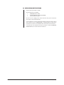
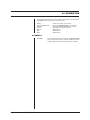
®
✓Check
Inter
by
ICIMI1000
Interface Cable
Installation/
Operation Manual
C1014M-B (10/97)
Pelco • 3500 Pelco Way, Clovis, CA 93612-5699 • USA • www.pelco.com
In North America and Canada: Tel (800) 289-9100 • FAX (800) 289-9150
International Customers: Tel (1-559) 292-1981 or FAX (1-559) 348-1120
®
CONTENTS
Section
Page
1.0 GENERAL .................................................................................................. 1
1.1 IMPORTANT SAFEGUARDS AND WARNINGS ............................... 1
1.2 UNPACKING INSTRUCTIONS .......................................................... 2
2.0 DESCRIPTION .......................................................................................... 3
2.1 MODELS ............................................................................................ 3
3.0 INSTALLATION FOR CASH REGISTERS ................................................ 4
3.1 LOCATING THE PRINTER CONNECTION ....................................... 4
3.2 INTER-CHECK® PROGRAMMING .................................................... 4
3.2.1 Procedures for the Gilbarco TCR/15 Cash Registers ............ 5
3.2.2 Procedures for the Gilbarco “G-Site” Cash Registers ............ 6
3.2.3 Procedures for the Koppens/Schlumberger Micromax
1000, 2000, and 3000 Pro Cash Registers ........................... 6
3.2.4 Procedures for the Suntronics Station Minder 890, 960, and
2000 Cash Registers ............................................................. 7
3.2.5 Procedures for the Verifone Ruby Super System
Cash Registers ...................................................................... 7
3.3 INTER-CHECK® WIRING KITS ......................................................... 8
4.0 INSTALLATION FOR ATM MACHINES ..................................................... 10
4.1 INTER-CHECK® PREPARATION ..................................................... 10
4.2 CONNECTING THE INTERFACE .................................................... 10
4.3 INTER-CHECK® PROGRAMMING ................................................... 12
4.4 INTER-CHECK® WIRING KITS ........................................................ 12
5.0 SPECIFICATIONS .................................................................................... 13
6.0 WARRANTY AND RETURN INFORMATION ........................................... 14
LIST OF ILLUSTRATIONS
Figure
1
2
3
Page
Wiring Diagram for One Cash Register or One ATM Machine ........... 9
Wiring Diagram for Two Cash Registers or Two ATM Machines ....... 9
ATM Machine Interface Cable Installation ........................................ 11
REVISION HISTORY
Manual #
C1014M
ii16
Date
—
Comments
Original version.
C1014M-A
9/93
Rev. A. Completely revised.
C1014M-B
10/97
Rev. B. Completely revised. Includes information
replacing the ICISU890, ICIGITCR15, and ICIATM25
interface cables with the ICIMI1000 interface cable.
Revised illustrations for clarity.
Pelco Manual C1014M-B (10/97)
1.0 GENERAL
1.1 IMPORTANT SAFEGUARDS AND WARNINGS
Prior to installation and use of this product, the following WARNINGS should be
observed.
1.
Installation and servicing should only be done by Qualified Service Personnel
and conform to all Local codes.
2.
Unless the unit is specifically marked as a NEMA Type 3, 3R, 3S, 4, 4X, 6, or
6P enclosure, it is designed for indoor use only and it must not be installed
where exposed to rain and moisture.
3.
Use only installation methods and materials capable of supporting four (4)
times the maximum specified load.
4.
Only use replacement parts recommended by Pelco.
The product and/or manual may bear the following marks:
This symbol indicates that dangerous voltage constituting a
risk of electric shock is present within this unit.
This symbol indicates that there are important operating and
maintenance instructions in the literature accompanying this
unit.
CAUTION:
RISK OF
ELECTRIC SHOCK.
DO NOT OPEN.
CAUTION:
TO REDUCE THE RISK OF ELECTRICAL SHOCK,
DO NOT REMOVE COVER. NO USERSERVICEABLE PARTS INSIDE. REFER SERVICING
TO QUALIFIED SERVICE PERSONNEL.
Please thoroughly familiarize yourself with the information
in this manual prior to installation and operation.
Pelco Manual C1014M-B (10/97)
1
1.2 UNPACKING INSTRUCTIONS
Unpack and inspect all parts carefully.
The following items are supplied:
1
1
1
ICIMI1000 Interface Cable
Installation/Operation Manual (C1014M-B)
Interface Extension Cable
Be sure to save the shipping carton, boxes and inserts. They are the safest material in which to make future shipments.
If an item appears to have been damaged in shipment, replace it properly in its box
and contact the factory at 1-800-289-9100 or 1-559-292-1981 for a replacement.
(International customers fax 1-559-348-1120 for authorization and instructions.)
If an item needs to be returned to the factory for repair, consult the WARRANTY
AND RETURN section of this manual for instructions.
2
Pelco Manual C1014M-B (10/97)
2.0 DESCRIPTION
The information in this manual covers the installation and operation of the Inter-Check®
ICIMI1000 Interface Cable with the following systems:
Gilbarco
Koppens/Schlumberger
Suntronics
Verifone
Diebold
IBM
NCR
TCR/15 and “G-Site” cash registers
Micromax 1000/2000/3000 Pro cash registers
Station Minder 890, 960, 2000 cash registers
Ruby Super System cash registers
ATM machines
ATM machines
ATM machines
2.1 MODELS
ICIMI1000
Pelco Manual C1014M-B (10/97)
Interface Cable to interface the Inter-Check® ICI1000 and ICI2000
Series Cash Register Interface System with Electronic Cash
Registers (ECRs) and Automated Teller Machines (ATMs).
3
3.0 INSTALLATION FOR CASH REGISTERS
CAUTION: Installation
should be in accordance
with all applicable local
and national electric
codes, utilizing approved
materials only.
This section covers the installation of the ICIMI1000 interface cable with the Gilbarco
TCR/15 and “G-Site”; Koppens/Schlumberger Micromax 1000, 2000, 3000 Pro;
Suntronics Station Minder 890, 960, 2000; and Verifone Ruby Super System cash
registers.
The following should be noted prior to installation:
NOTE: The Pelco Gilbarco TCR/
15 register interface utilizes the display port on the cash register display. It Is not a printer connection
like most of our interfaces.
3.1 LOCATING THE PRINTER CONNECTION
1.
Locate the printer and unplug the cash register printer cable from the printer.
(On the Gilbarco TCR/15, locate the port labeled DISPLAY. This connection
will be found on the back and underneath the register. If the display port is not
labeled, follow the cable from the customer display back to the register.)
2.
Plug Pelco’s printer interface (ICIMI1000) into the 25 pin D-SUB connector on
the printer. (On the Gilbarco TCR/15, plug Pelco’s display interface (ICIMI100)
directly into the register display port. The Interface Extension Cable is used to
interface the register display port.)
3.
Plug the register printer cable into the Pelco ICIMI1000 interface. (You can
use either the male or female 25 pin D-SUB connector.)
4.
If the Pelco Inter-Check® is to be located more than four feet from the printer,
you can run wiring to where the Inter-Check® is located using the ICI1000
wiring kit (supplied with the Inter-Check® unit). Refer to Figure 1 or Figure 2 to
properly configure the wiring for the Inter-Check® unit.
5.
Make sure all connections are tight.
6.
Check register and display for proper operation.
Proceed to Section 3.2, INTER-CHECK® PROGRAMMING.
3.2 INTER-CHECK® PROGRAMMING
Inter-Check® must have communication parameters programmed in order to communicate with the registers. Refer to the Inter-Check® installation/operation manual
for complete information about system programming. Perform the following steps
to program the Inter-Check® communication parameters:
1.
Enter the Main Menu by pressing “ENT” on the keypad for programming mode.
2.
Inter-Check® 1000S users press “1” on the keypad for Channel 1 Setup.
Inter-Check® 2000D users press “1” or “2” depending on the channel you are
using for data display.
3.
4
Press “1” for Communication Setup in the Channel Menu. Press “1” to setup
Communication Parameters. On the monitor screen, you will see the current
communication parameters followed by the “Baud=?” statement.
Pelco Manual C1014M-B (10/97)
To define communication parameters for baud rate, type in the appropriate
data and press “ENT” to save. To define all the other communication parameters, type the appropriate data for each parameter. (Refer to the section for
Procedures for the Verifone Ruby Super System Cash Registers to setup communication parameters for the Verifone Ruby Cash Registers.)
Use the following communication parameters for Koppens/Schlumberger
Micromax 1000, 2000, 3000 Pro; Suntronics Station Minder 890, 960, 2000
cash registers; and Gilbarco TCR/15 and “G-Site” cash registers:
•
•
•
•
•
•
•
•
•
•
1200 baud (Koppens/Schlumberger Micromax and Suntronics Station
Minder Printer Interface)
4800 baud (Gilbarco TCR/15 and “G-Site” Display Interface)
9600 baud (Gilbarco “G-Site” Printer Interface)
7 Bits (Koppens/Schlumberger Micromax and Gilbarco “G-Site” Printer
Interface)
8 Bits (Gilbarco and Suntronics)
Parity OFF (Koppens/Schlumberger Micromax, Suntronics Station Minder,
and Gilbarco TCR/15 Printer Interface)
Parity EVEN (Gilbarco “G-Site” Printer Interface)
NRZ
ASCII
Data Invert
4.
Press “ESC” on the keypad to save this selection.
5.
Press “2” for Data Format/Communication Protocol. Press “ENT” or the up
and down arrow cursor control keys to scroll through protocol options. The
selection you use will show “Selected: RS232 Standard Printer” on the monitor.
6.
Press “ESC” three times to save the selection and return to monitoring mode.
7.
Test for proper operation.
Proceed to the section for your specific cash register.
3.2.1 Procedures for the Gilbarco TCR/15 Cash Registers
The following procedures are to be performed on the Gilbarco TCR/15 Cash
Registers:
1.
NOTE: The connection for the cus-
tomer display interface is located
underneath the register. Use the
25-pin extension cable supplied
with the ICIMI1000 to plug into this
register.
Pelco Manual C1014M-B (10/97)
If a scrolling message from the register’s customer display continues to repeat itself on the video screen, you can command Inter-Check® to stop receiving the message by programming the following:
a.
Press “ENT” on the keypad for programming mode.
b.
Press “2” for System Program Menu.
c.
Press “2” for End of Line Stop selection.
d.
Turn “End of Line Stop” on and then press “ESC” three times to back out
of the menus and reinitialize Inter-Check®.
2.
Be sure the cables on the wiring kit are connected to the yellow and black
terminals only.
3.
Set the SW1 switch on the ICIMI1000 interface cable toward the female plug.
5
3.2.2 Procedures for the Gilbarco “G-Site” Cash Registers
The following procedures are to be performed on the Gilbarco “G-Site” Cash Registers:
NOTE: Because the baud rate of
1.
Use the 8-pin modular adapter supplied with the ICIMI1000 when interfacing
to this register.
2.
Be sure the cables on the wiring kit are connected to the yellow and black
terminals only.
3.
If you want journal printer information, but there is no printer plugged into the
printer port, the interface is still possible. Select the “None Printer” or “Security” setting when booting the register system at the start of the day. This will
result in journal information being sent to the printer port without requiring a
printer. Use the communication parameters in Section 3.2, Inter-Check® Programming, to program this interface.
4.
If a scrolling message from the register’s customer display continues to repeat itself on the video screen, you can command Inter-Check® to stop receiving the message by programming the following:
the journal printer is adjustable,
occasionally the printer may be set
for one of the following baud rates:
4800, 2400, 1200.
a.
Press “ENT” on the keypad for programming mode.
b.
Press “2” for System Program Menu.
c.
Press “2” for Carriage Return Control Menu.
Press “2” for End of Line Stop selection.
d.
Turn “End of Line Stop” on and then press “ESC” three times to back out
of the menus and reinitialize Inter-Check®.
5. Set the SW1 switch on the ICIMI1000 interface cable toward the male plug.
3.2.3 Procedures for the Koppens/Schlumberger Micromax
1000, 2000, and 3000 Pro Cash Registers
The following procedures are to be performed on the Koppens/Schlumberger
Micromax 1000, 2000, and 3000 Pro Cash Registers:
6
1.
Be sure the cables on the wiring kit are connected to the yellow and black
terminals only.
2.
If the communication parameters settings in the Inter-Check® Programming
section do not work correctly, check the switch settings underneath the printer
to determine printer communication settings and adjust the Inter-Check® programming to match the new printer settings.
3.
Set the SW1 switch on the ICIMI1000 interface cable toward the male plug.
Pelco Manual C1014M-B (10/97)
3.2.4 Procedures for the Suntronics Station Minder 890,
960, and 2000 Cash Registers
The following procedures are to be performed on the Suntronics Station Minder
890, 960, and 2000 Cash Registers
1.
Be sure the cables on the wiring kit are connected to the yellow and black
terminals only.
2.
If the communication parameters settings in the Inter-Check® Programming
section do not work correctly, check the switch settings underneath the printer
to determine printer communication settings and adjust the Inter-Check® programming to match the new printer settings.
Also, printer communication settings can be determined by proceeding with
one of following methods:
3.
a.
Turn the printer “off”. Press the printer “line feed” and “form feed” buttons
at the same time while you turn the printer “on”. Continue to hold the
buttons down as the printer prints the proper communication settings on
a receipt.
b.
Turn the printer “off”. Press either the printer “line feed” or “form feed”
button while you turn the printer “on”. Continue to hold the button down
as the printer prints the proper communication settings on a receipt.
Set the SW1 switch on the ICIMI1000 interface cable toward the male plug.
3.2.5 Procedures for the Verifone Ruby Super System
Cash Registers
The following procedures are to be performed on the Verifone Ruby Super System
Cash Registers
1.
Configure the PIM default before setting up communication parameters by
programming the following:
a.
Press “ENT” on the keypad to enter programming mode.
b.
Press “6” for Diagnostics.
c.
Press “8” for (DL) PIM Default Load.
d.
Press “ESC” to exit programming mode.
2. Configure the communication parameters by programming the following:
Pelco Manual C1014M-B (10/97)
a.
Press “ENT” on the keypad to enter programming mode.
b.
Press “1” for Channel 1 Setup.
c.
Press “2” for Data Format/Communication Protocol.
d.
Press “ENT” or the up and down arrow cursor control keys to scroll through
your protocol options. The selection you use will show “Selected: RS232
Standard Printer” on the monitor.
e.
Press “ESC” three (3) times to save the selection and return to monitoring mode.
3.
Be sure the cables on the wiring kit are connected to the yellow and black
terminals only.
4.
The ICIMI1000 interface cable must be plugged into the printer rather than
the register in order for this interface to operate.
7
5.
Verifone uses the Epson Model TM930II as the standard printer on this register. If you are using the Epson Model TM950II printer, with 9-pin “D” style
connector, you will need to use the Pelco ICIDRP interface cable.
6.
Set the SW1 switch on the ICIMI1000 interface cable toward the male plug.
Proceed to Section 3.3, INTER-CHECK® WIRING KITS.
3.3 INTER-CHECK® WIRING KITS
Refer to the wiring configurations shown in Figure 1 and 2 if you are installing
the Inter-Check® unit more than four feet away from the printer. A maximum of
1,500 feet (457.2 m) of 18 AWG shielded wire is recommended (not provided).
One (1) ICI1000WK wiring kit is provided with the ICI1000SE and ICI1000SI InterCheck® unit. This kit includes the following components:
2
1
RJ14 phone jacks
Straight-through 6 conductor phone cable
One (1) ICI2000WK wiring kit is provided with the ICI2000D Inter-Check® unit. This
kit includes the following components:
3
1
8
RJ14 phone jacks
Straight-through 6 conductor phone cable
Pelco Manual C1014M-B (10/97)
STRAIGHT
THROUGH
PHONE CABLE
TO ICI1000S
INTER-CHECK®
UNIT
WH
BL
BK
YL
RD
GR
WIRING ABBREVIATION TABLE
USER SUPPLIED
18 AWG SHIELDED WIRE
IS RECOMMENTED
WH
BL
BK
RD
YL
GR
ICIMI1000
INTERFACE
CABLE
WH
BL
BK
YL
RD
GR
=
=
=
=
=
=
WHITE WIRE
BLUE WIRE
BLACK WIRE
RED WIRE
YELLOW WIRE
GREEN WIRE
Figure 1. Wiring Diagram for One Cash Register or One ATM Machine
STRAIGHT
THROUGH
PHONE CABLE
TO ICI2000D
INTER-CHECK®
UNIT
WH
BL
BK
YL
RD
GR
USER SUPPLIED
18 AWG SHIELDED WIRE
IS RECOMMENDED
FROM ICIMI1000
INTERFACE CABLE
PORT #1
FROM ICIMI1000
INTERFACE CABLE
PORT #2
WIRING ABBREVIATION TABLE
WH
BL
WH
BL
BK
YL
BK
YL
RD
GR
RD
GR
WH
BL
BK
RD
YL
GR
=
=
=
=
=
=
WHITE WIRE
BLUE WIRE
BLACK WIRE
RED WIRE
YELLOW WIRE
GREEN WIRE
Figure 2. Wiring Diagram for Two Cash Registers or Two ATM Machines
Pelco Manual C1014M-B (10/97)
9
4.0 INSTALLATION FOR ATM MACHINES
This section covers the installation of the ICIMI1000 interface cable with the Diebold,
IBM, and NCR ATM machines.
4.1 INTER-CHECK® PREPARATION
CAUTION: Installation
1.
should be in accordance
with all applicable local
and national electric
codes, utilizing approved
materials only.
Check to see if Pelco supports the communication protocol your ATM is running. ATMs having a different protocol may emulate one of the supported protocols listed.
The ATM protocols that Pelco supports are:
Diebold 910/911 : IBM 2260
Diebold 910/911 : IBM 2265
Diebold 910/911 : IBM 3275
Diebold 910/911 : IBM 3624
IBM Native Mode
Diebold 910/911 : NCR751/279
NCR Native Mode
Diebold 910/911 : SNA/SDLC
Diebold 910/911 : TC 500/700
Diebold 910/911 : TC 500/700 Sync
2.
Check the appropriate hardware connection needed to connect into the ATM’s
modem. Usually the connection will use the ICIMI1000 interface cable with 25-pin
connector. Contact the factory If the ATM uses a 9-pin or other connector.
3.
Find out the communication parameters (such as baud rate and parity) needed
by the ATM’s modem. This information is available from the bank support group
or ATM network for your particular ATM machine.
Proceed to Section 4.2, CONNECTING THE INTERFACE.
4.2 CONNECTING THE INTERFACE
The Inter-Check® interface cable connection between the ATM machine and the
modem is a fairly easy external connection (see Figure 3). Refer to Figure 1 for the
wiring diagram for one ATM machine and Figure 2 for the wiring diagram for two
ATM machines.
Perform the following procedures to interface the ATM machine and the Inter-Check®:
1.
Disconnect the ATM data cable that plugs into the modem port.
2.
Connect the ICIMI1000 to the ATM network modem
3.
Connect the ATM data cable into the open end of the ICIMI1000.
4.
Connect the RJ14 plug on the ICIMI1000 interface cable to the DATA IN connection on the Inter-Check® unit.
5.
Set the SW1 switch on the ICIMI1000 interface cable toward the male plug (in
the direction of the gray phone cable.)
Proceed to Section 4.3, INTER-CHECK® PROGRAMMING
10
Pelco Manual C1014M-B (10/97)
ATM MACHIN E
P LA C E IN T E R FA C E
C A B LE H E R E
( IC IMI1000)
AT M N E T W OR K MOD E M
Figure 3. ATM Machine Interface Cable Installation
Pelco Manual C1014M-B (10/97)
11
4.3 INTER-CHECK® PROGRAMMING
NOTE: If your protocol is Diebold
1.
Select the appropriate communication protocol your ATM is using. Refer to
your Inter-Check® manual for a complete explanation on proper programming.
2.
Set the ATM device addresses to “00”.
3.
Make sure the Inter-Check® unit receives data. The data seen on the monitor
reflects transactions of all ATMs connected on your ATM’s network.
4.
Run a test transaction on the ATM that you want to monitor.
5.
As the transaction is displayed on the monitor, the address of your ATM will
appear at the top of the transaction display as a hex number such as “10H”.
This number must be converted to a decimal number using the table in the
appendix in the back of the ICI1000 and ICI2000 manual. This is the address
that you need to enter into the Inter-Check unit under DEVICE ADDRESSES
in the Communication Setup menu.
910/911 : SNA/SDLC, you must
enter the address of your ATM into
both the “Device Address 1” and
“Device Address 2” configuration
settings.
Proceed to Section 4.4, INTER-CHECK® WIRING KITS.
4.4 INTER-CHECK® WIRING KITS
Refer to the wiring configurations shown in Figure 1 and 2 if you are installing the
Inter-Check® unit more than four feet away from the printer. A maximum of 1,500
feet (457.2 m) of 18 AWG shielded wire is recommended (not provided).
One (1) ICI1000WK wiring kit is provided with the ICI1000SE and ICI1000SI InterCheck® unit. This kit includes the following components:
2
1
RJ14 phone jacks
Straight-through 6 conductor phone cable
One (1) ICI2000WK wiring kit is provided with the ICI2000D Inter-Check® unit. This
kit includes the following components:
3
1
12
RJ14 phone jacks
Straight-through 6 conductor phone cable
Pelco Manual C1014M-B (10/97)
5.0 SPECIFICATIONS
GENERAL
Environment:
Indoor
Operating
Temperature:
32° to 120° F (0° to 49°C)
Weight
Unit
0.45 lbs (0.20 kg)
Shipping
0.60 lbs (0.27 kg)
Connectors:
One (1) male 25 pin D-SUB connector
One (1) female 25 pin D-SUB connector
One (1) RJ-14 male connector
Switching:
Micro-mini SPDT slide switch
(Design and product specifications subject to change without notice.)
Pelco Manual C1014M-B (10/97)
13
6.0 WARRANTY AND RETURN INFORMATION
WARRANTY
Pelco will repair or replace, without charge, any merchandise proved defective in material or
workmanship for a period of one year after the date of shipment.
Exceptions to this warranty are as noted below:
• Five years on FT/FR8000 Series fiber optic products.
• Three years on Genex® Series products (multiplexers, server, and keyboard).
• Three years on Camclosure® and fixed camera models, except the CC3701H-2, CC3701H-2X,
CC3751H-2, CC3651H-2X, MC3651H-2, and MC3651H-2X camera models, which have a fiveyear warranty.
• Two years on standard motorized or fixed focal length lenses.
• Two years on Legacy®, CM6700/CM6800/CM9700 Series matrix, and DF5/DF8 Series fixed
dome products.
• Two years on Spectra®, Esprit®, ExSite™, and PS20 scanners, including when used in
continuous motion applications.
• Two years on Esprit® and WW5700 Series window wiper (excluding wiper blades).
• Eighteen months on DX Series digital video recorders, NVR300 Series network video
recorders, and Endura ™ Series distributed network-based video products.
• One year (except video heads) on video cassette recorders (VCRs). Video heads will be
covered for a period of six months.
• Six months on all pan and tilts, scanners or preset lenses used in continuous motion applications
(that is, preset scan, tour and auto scan modes).
Pelco will warrant all replacement parts and repairs for 90 days from the date of Pelco shipment.
All goods requiring warranty repair shall be sent freight prepaid to Pelco, Clovis, California. Repairs
made necessary by reason of misuse, alteration, normal wear, or accident are not covered under
this warranty.
Pelco assumes no risk and shall be subject to no liability for damages or loss resulting from the
specific use or application made of the Products. Pelco’s liability for any claim, whether based on
breach of contract, negligence, infringement of any rights of any party or product liability, relating
to the Products shall not exceed the price paid by the Dealer to Pelco for such Products. In no event
will Pelco be liable for any special, incidental or consequential damages (including loss of use, loss
of profit and claims of third parties) however caused, whether by the negligence of Pelco or
otherwise.
The above warranty provides the Dealer with specific legal rights. The Dealer may also have
additional rights, which are subject to variation from state to state.
If a warranty repair is required, the Dealer must contact Pelco at (800) 289-9100 or (559) 292-1981
to obtain a Repair Authorization number (RA), and provide the following information:
1. Model and serial number
2. Date of shipment, P.O. number, Sales Order number, or Pelco invoice number
3. Details of the defect or problem
If there is a dispute regarding the warranty of a product which does not fall under the warranty
conditions stated above, please include a written explanation with the product when returned.
Method of return shipment shall be the same or equal to the method by which the item was received
by Pelco.
RETURNS
Pelco, the Pelco logo, Camclosure, Esprit,
Genex, Legacy, and Spectra are registered
trademarks of Pelco.
Endura and ExSite are trademarks of Pelco.
© Copyright 1997, Pelco. All rights reserved.
14
In order to expedite parts returned to the factory for repair or credit, please call the factory at (800)
289-9100 or (559) 292-1981 to obtain an authorization number (CA number if returned for credit,
and RA number if returned for repair).
All merchandise returned for credit may be subject to a 20% restocking and refurbishing charge.
Goods returned for repair or credit should be clearly identified with the assigned CA or RA number
and freight should be prepaid. Ship to the appropriate address below.
If you are located within the continental U.S., Alaska, Hawaii or Puerto Rico, send goods to:
Service Department
Pelco
3500 Pelco Way
Clovis, CA 93612-5699
If you are located outside the continental U.S., Alaska, Hawaii or Puerto Rico and are instructed
to return goods to the USA, you may do one of the following:
If the goods are to be sent by a COURIER SERVICE, send the goods to:
Pelco
3500 Pelco Way
Clovis, CA 93612-5699 USA
If the goods are to be sent by a FREIGHT FORWARDER, send the goods to:
Pelco c/o Expeditors
473 Eccles Avenue
South San Francisco, CA 94080 USA
Phone: 650-737-1700
Fax: 650-737-0933
Pelco Manual C1014M-B (10/97)