
1
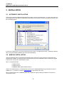
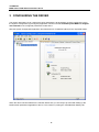
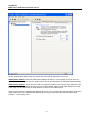
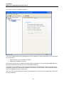
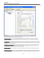
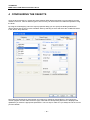
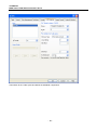
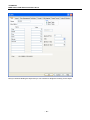
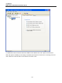
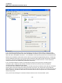
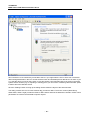
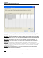
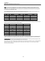
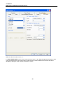
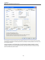
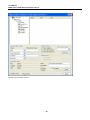
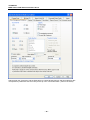
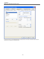
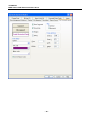
7TOMRTCP
IGSS Omron FINS Ethernet Interface Driver
User’s Manual
Seven Technologies
7-Technologies A/S * Bistruphave 3 * DK-3460 Birkerød * Denmark
Phone: +45 45 900 700 * Fax: +45 45 900 701 * CVR no. DK 73 63 41 13
E-mail: [email protected] World Wide Web: http://www.7t.dk
7TOMRTCP
IGSS Omron FINS Ethernet Interface driver
DISCLAIMER
:
This is an unpublished work, the copyright of which vests in
SEVEN TECHNOLOGIES A/S.
All rights reserved.
The information contained herein is the property of SEVEN
TECHNOLOGIES and is supplied without liability for errors or omissions.
No part may be reproduced or used except as authorised by contract or
other written permission.
The copyright and the foregoing restriction on reproduction and use extend
to all media in which the information may be embodied.
- 1-
7TOMRTCP
IGSS Omron FINS Ethernet Interface driver
CONTENTS:
1
2
3
4
5
6
7
INTRODUCTION ................................................................................................................. 3
1.1
Software Requirements .......................................................................................... 3
1.2
Hardware Requirements ......................................................................................... 3
INSTALLATION ................................................................................................................... 4
2.1
Automatic Installation.............................................................................................. 4
2.2
Manual Installation .................................................................................................. 4
CONFIGURING THE DRIVER ............................................................................................ 6
CONFIGURING THE OBJECTS ....................................................................................... 11
4.1
Supported Memory Types .................................................................................... 12
4.2
Configuring a Clock-Object................................................................................... 13
USE WITH GPRS NETWORKS........................................................................................ 16
PERFORMANCE AND THROUGHPUT ........................................................................... 29
ERROR CODES ................................................................................................................ 30
- 2-
7TOMRTCP
IGSS Omron FINS Ethernet Interface driver
1 INTRODUCTION
This document describes how to set up and troubleshoot the IGSS 7TOMRTCP Interface Driver.
The driver implements the Omron FINS protocol stack on Ethernet using UDP/IP.
1.1 SOFTWARE REQUIREMENTS
None (see Hardware Requirements below).
The driver is designed to be used with IGSS version 8.0 and higher.
1.2 HARDWARE REQUIREMENTS
The driver requires a standard NIC interface with TCP/IP (UDP/IP) installed.
An Ethernet port supporting TCP/IP (UDP/IP) and the FINS protocol is required on the PLC’s. Please refer to
Omron documentation for cable, setup and wiring instructions.
- 3-
7TOMRTCP
IGSS Omron FINS Ethernet Interface driver
2 INSTALLATION
2.1 AUTOMATIC INSTALLATION
The driver is normally installed automatically along with the rest of the IGSS system. To verify if the driver has
been installed open the System Configuration (sysconfig.exe) and check if a driver with ID:85 is present in the
list of available drivers:
If the driver is present then you can proceed to the next section: “Configuring the Driver”, otherwise install the
driver using the manual installation procedure described below.
2.2 MANUAL INSTALLATION
Using the following step-by-step guide will install the driver manually on a PC where the IGSS system has
already been installed. You need to stop the IGSS system prior to the installation and you need to be logged
in with a user account with “Administrator” rights.
Step 1: Verify that the files:
7TOMRTCP.DLL
7TOMRTCPc.DLL
COMMDRV.REG (latest updated version)
exists in the GSS\ directory. If the files doesn’t exists run the IGSSUpdateClient to get the files from the 7T
WEB server – or contact 7T Support ([email protected]) to get the files via e-mail.
Step 2: Double-click on the COMMDRV.REG file to import the registry settings needed for the system to
recognize the driver.
- 4-
7TOMRTCP
IGSS Omron FINS Ethernet Interface driver
The driver is now installed.
- 5-
7TOMRTCP
IGSS Omron FINS Ethernet Interface driver
3 CONFIGURING THE DRIVER
This section describes how to configure the driver parameters. All parameters must be configured by using
the System Configuration (sysconfig.exe) application. Please note that the IGSS system MUST be stopped
and restarted for the configured parameters to take effect.
Start the System Configuration application and add the driver 7TOMRTCP (ID:85) to the requested station.
When the driver has been added to the relevant station then you are ready to proceed with setting up the
FINS network parameters applicable to the PC. This is done by clicking the “FINS Network Setting” tab:
- 6-
7TOMRTCP
IGSS Omron FINS Ethernet Interface driver
On the “FINS Network Setting” page you specify the FINS network parameters for the PC:
FINS Network Address: Select the FINS network address for the PC. This is typically 0, but can be to any
applicable number between 0 and 127. Please refer to Omron documentation for setting up network topology.
FINS Network Address: Just as any PLC node on the network needs to have a unique node address the PC
also needs a FINS Node Address to identify it on the FINS Network. Select a FINS node address for the PC
in the range 1 to 254. Make sure the node address is unique on the FINS network.
Once you have set up the FINS Network Settings for the PC you are ready to proceed with setting up the PLC
nodes. Right-click on the “OMRON FINS Ethernet driver” tag in the left mode tree view and select “New
Interface…” in the popup menu:
- 7-
7TOMRTCP
IGSS Omron FINS Ethernet Interface driver
The “Connect Through IP Network” appears.
The Omron FINS Ethernet driver is designed to use one IP address for each node and thus you should select
one of the options:
•
•
Connect directly. One IP Address one node.
GPRS. One IP Address one node.
The “Connect directly. One IP Address one node” option is designed for use on fixed (ADSL/SDSL/WiFi etc.)
type networks where the PC and the PLC is connected permanently.
The “GPRS. One IP Address one node” option is designed for use on GPRS type network where the user is
charged for the amount of data being transmitted on the network. See the section “Use with GPRS networks”
section for detailed description on this option.
Add a PLC node by right clicking the channel in the left side tree-view and select the “New Node” menu when
the pop-up appears:
- 8-
7TOMRTCP
IGSS Omron FINS Ethernet Interface driver
Each PLC node requires a few fundamental parameters:
IGSS node number: This is the node number which IGSS uses to reference a unique PLC. This node
number is required when binding and IGSS atom (tag) to a register in the PLC. Any number from the drop
down list can be used.
Processor type: Click this drop down box to select the PLC type (CS/CJ or CV). If the PLC node you want to
connect to belongs to the Omron CS/CJ family select CS/CJ. If the PLC node you want to connect to belongs
to the Omron CV family select CV.
IP address of the PLC node: Specify the IP address of the PLC node you want to connect to. Please make
sure that this IP is reachable from the PC (e.g. by using the IP “ping” command). Please refer to Omron
documentation for setting up the IP address of the PLC node.
UDP port number: Set to UDP port to be used for FINS communication. This port number will typically be
9600.
FINS network address: Specify the FINS network address of the PLC node. Valid values are in the range 0
to 127. 0 normally specifies a Local Network. Please refer to Omron documentation for detailed description of
- 9-
7TOMRTCP
IGSS Omron FINS Ethernet Interface driver
how FINS Network address, FINS Node address and FINS Unit address allows you to specify network
topology.
FINS node address: Specify the FINS node address of the PLC node. Valid values are in the range 1 to 254.
FINS unit address: Specify the FINS unit address of the required connection. Valid values are in the range 0
to 255. 0 normally specifies the CPU Unit. 16 through 31 are normally used for CPU Bus Units. Please refer
to Omron FINS documentation for detailed description of FINS unit addresses.
Communication timeout: This parameter allows you to specify how long the IGSS FINS Ethernet driver will
wait for a response from the PLC before retrying the transmission. Please be aware that the UDP/IP protocol
doesn’t guarantee delivery, and might thus be subject to lost telegrams on the network without send and/or
receiver will know about it.
Automatic timesynch interval: The IGSS FINS Ethernet driver has a build in time synchronisation function
which allows you to specify if the driver should synchronize the internal clock in the PLC node with the clock
on the PC. It is always the local time on the PC with will be used when this function is used and the PC will
always be time-master (i.e. it is the PC clock which will be sent to all nodes requesting this service). If you
don’t want the driver to synchronize the clocks then specify 0 (null) as the interval, this will disable the
automatic time synchronization service in the driver for this node.
Telegram retries: Here you can specify the number of telegram reties the driver should use before issuing a
communication fault. The default value is 3 which suit most applications. If you experience frequent
communication faults you might try to increase this parameter. Please be aware that the UDP/IP protocol
doesn’t guarantee delivery, and might thus be subject to lost telegrams on the network without send and/or
receiver will know about it.
- 10 -
7TOMRTCP
IGSS Omron FINS Ethernet Interface driver
4 CONFIGURING THE OBJECTS
Once the driver and the PLC nodes have been defined, IGSS Objects and Atoms can be linked to process
variable in the PLC. Various different types of PLC memory can be accessed for read/write operations using
the driver.
By using the “Edit Mapping” tab in the object properties dialog you can specify the binding between the
object’s atoms and the PLC process variables. Start by selecting an atom and select the 7TOMRTCP driver
in the “Driver” drop down list:
Now select the desired PLC node number and continue by setting be desired Device. Then specify the
number (register number within the device type). Note that the corresponding Mnemonic is displayed and
updated as you select the appropriate parameters. This is a help to make sure you always bind to the correct
process variable.
- 11 -
7TOMRTCP
IGSS Omron FINS Ethernet Interface driver
Continue this process for each atom on the object and save the parameters by clicking the OK button when
finished.
4.1 SUPPORTED MEMORY TYPES
The driver supports a number of different device types in the PLC:
16-Bit types (Words):
Memory Type
DM Area
CIO Area
HR (Holding Bits) Area
AR (Auxiliary Bits) Area
WR (Work) Area
Timer Value
Counter Value
EM Bank (Current)
EM Bank N (Specific)
PLC Clock
Processor type
CS/CJ
R/W
R/W
R/W
R/W
R/W
R/W
R/W
R/W
R/W
R/W
CV
R/W
R/W
N/A
R/W
N/A
R/W
R/W
R/W
R/W
R/W
Please observe that the applicable range and availability for each Memory Type will vary depending on the
specific Omron PLC type.
1-Bit (Boolean) types:
Memory Type
DM Area
CIO Area
HR (Holding Bits) Area
AR (Auxiliary Bits) Area
WR (Work) Area
EM Bank (Current)
EM Bank N (Specific)
PLC Clock
Processor type
CS/CJ
R/W
R/W
R/W
R/W
R/W
R/W
R/W
R/W
CV
R
R/W
N/A
R
N/A
R/W
R
R/W
R: Read. W: Write. N/A: Not Applicable.
These addressing methods allow you to bind to any type of process value in the PLC.
Please note that if you want to bind to a 32 bit (DWORD) value then use word addressing and specify the
external type as one of the supported 32 bit types, then the system will automatically do the correct
addressing.
If you e.g. want to bind to a floating point process value at DM 0254 you should specify: DM 0254 and select
the external type FLOAT. Then the Driver will automatically fetch both DM 0254 and DM 0255 and interpret
the content as a floating point (IEEE float) value.
Please note that all bit types are *only* one bit values when written as a command to the PLC. I.e. if you bind
a digital command to DM 012 Bit 6 and send the command “->1” then *only* DM012.6 is set. This means that
you can’t send complex commands that require more than one bit to be set/reset.
The driver automatically fetches at least 16 bits when a specific bit is referenced. If you e.g. define a digital
object which mimics the state of 3 bits combined (e.g. DM 013.3, DM 013.7 and DM 013.9) then the driver
automatically fetches the range DM 013.3 through DM 013.9 to ensure that all bits are read from the PLC.
- 12 -
7TOMRTCP
IGSS Omron FINS Ethernet Interface driver
IT IS HIGHLY RECOMMENTED to use Data Register as the primary memory type for exchanging variable
information between IGSS and the PLC. Read- and especially write operations directly to Output, Timers and
Counters cannot be verified by the PLC program and might thus lead to hazards.
4.2 CONFIGURING A CLOCK-OBJECT
The IGSS FINS Ethernet driver allows the user to configure objects which binds to the PLC real time clock.
This enables you to make UI which allows the user to monitor and set the real time clock in the PLC.
To map an object/atom to a component of the real time PLC clock select the Memory Type: “PLC Clock
(Word)”. Then select the specific offset of the real time clock component you want to bind to according to the
table below:
Offset
0
1
2
3
4
5
Component
Year (0-99)
Month (1-12)
Day (1-31)
Hour (0-23)
Minute (0-59)
Second (0-59)
If you want an IGSS atom to bind to the Minute component of the real time clock then you should select the
offset 4.
If you define the I/O mode attribute of the atom to be “i/o” (or just “out”) then the user will be able to set the
clock. Since the FINS protocol requires all clock parameters to be set concurrently the driver has been
designed such that the driver will automatically use the local time for any unspecified parameters. This means
that if the user only sets the minute component of the time, then the driver will fetch the Year, Month, Day,
Hour and Second from the PC (local time) and use these together with the user provided Minute component
to form a valid and useable FINS Write-Clock instruction.
External type should be set to FP16S.
An easy way to bind to all components of the real time clock is to use an IGSS table object. This use case is
shown in the following example.
Create an IGSS table object and bind it to the Memory Type “PLC Clock (Word)” and the Word Offset 0
(zero) in the “Edit Mapping” pane:
- 13 -
7TOMRTCP
IGSS Omron FINS Ethernet Interface driver
Then switch to the “Table” pane and define the individual components:
- 14 -
7TOMRTCP
IGSS Omron FINS Ethernet Interface driver
Now you are done binding the object and you can continue to design the mimic(s) for the object.
- 15 -
7TOMRTCP
IGSS Omron FINS Ethernet Interface driver
5 USE WITH GPRS NETWORKS
The IGSS Omron FINS Ethernet is primarily designed for use with fixed type Ethernet Networks (e.g.
industrial LAN or WAN Networks) where the PC and the Omron PLC’s are considered to be directly
connected. However the 7TOMRTCP interface driver can also be used on other types of IP based networks
as for example GPRS networks.
GPRS networks basically work as a normal IP network except that there will be a toll (cost) associated with
the amount of data you transmit on the network. The toll either comes as a cost pr. Mega Byte of data you put
in the “wire”, or as a flat rate agreement with the GPRS provider which limits the amount of data you are
allowed to put on the wire within a certain amount of time. This is in contrast to traditional LAN/WAN where
the cost of the infrastructure normally doesn’t depend on the amount of data you put on the wire once the
infrastructure (LAN/WAN network) is established.
The IGSS Omron FINS Ethernet driver allows you to set up the driver so that it will minimize the amount of
data on the wire and thus minimize the cost associated with using GPRS type networks (or other types of toll
based networks).
If you don’t care about the toll on data traffic on the GPRS network then you can treat the GPRS network as
any other LAN/WAN and just skip this section of the manual.
- 16 -
7TOMRTCP
IGSS Omron FINS Ethernet Interface driver
To enable this mode for the driver select the “GPRS. One IP Address one node” option as shown above.
When this option is enabled you can design a schedule which the driver will use when connecting to the PLC
node. Select the node and switch to the “Remote connection” pane:
- 17 -
7TOMRTCP
IGSS Omron FINS Ethernet Interface driver
In the “Connection Scheduling” section you can design a connection schedule either by entering specific
points in time during the day where the driver will establish connection or you can enter a fixed time interval
where the driver will establish connection – or a combination of both specific points in time and fixed intervals.
Based on this schedule the driver will connect to the PLC and read all configured data points (i.e. all the tags
you have defined in that node). Once the driver have read all the data it will stay idle until the next scheduled
connection. Using this schedule dramatically reduces the amount of data on the wire – but of course this
comes at the price of not actually being connected continuously.
In the “Connection hold time” section you might want to specify how long the driver should keep the
connection “open” it either the user sends a command or if the user forces the driver to establish a
connection through a dialup/connection object.
The “Normal connect hold time” option allows you to define how many seconds the driver will stay connected
(online) if the user forces the driver to make a connection to the PLC. The “Send cmd connect hold time”
option allows you to specify how many seconds the driver will stay online one the PLC node after the user has
send a command. This latter is useful if the user should be able to see the response of the command which
he/she has just sent.
Once you are done defining the connection schedule continue to the “Connection Misc.” pane:
- 18 -
7TOMRTCP
IGSS Omron FINS Ethernet Interface driver
Since the driver is not continuously connected to the PLC you might want the PLC to store one or historical
data in designated areas in the PLC and let the driver fetch and timestamp these data when it is online. If you
e.g. want the driver to only be online each 4 hours but require some important tags to be stored in the IGSS
system each 5 minutes (e.g. for reporting or trending) then you can use the “Collecting Historical Data” option
to define where the data are stored.
Click the “Settings” button to bring up the dialog used to define the layout of the historical data:
The dialog contains one row for each historical tag you want to define. The first 3 columns (Data Group,
Word Offset, Word Length) contain the fields to define where and how the data will be stored in IGSS. These
parameters are used to bind the data to specific objects.
- 19 -
7TOMRTCP
IGSS Omron FINS Ethernet Interface driver
Data Group: This field should always be set to 512. This is a fixed value which is used by the IGSS Omron
FINS Ethernet driver to recognize that this is historical data. The value 512 maps to the Memory Type
“Historical Data (Words)”.
Word Offset: This field id used to distinguish between the different historical data tags. It is recommended to
consequtive starting at 1 (one). The value of this field corresponds to the “Word Offset” parameter in the “Edit
Mapping” dialog when we bind the historical data to specific objects. See details below.
Word Length: This parameter is used to tell the driver the size of each of the historical data points. This
should be set to 1 if the historical data is a 16 bit data type and it should be set to 2 if the historical data is a
32 bit data type.
Read Code: This parameter tells the driver which Memory Type it should use when reading the historical
data. If the historical data is stored in DM area then this parameter should be 0. If the historical data is stored
in EM bank 0 then Read Code should be set to 160. If the historical data is stored in EM bank 1 then Read
Code should be set to 161 etc.
Start Addr: This is the address the driver will use to locate the latest (newest) historical data point for the
historical data series associated with this data point.
Interval: This is the interval the driver assumes between each of the samples in the historical data series.
Count: This is the depth of the historical data series.
- 20 -
7TOMRTCP
IGSS Omron FINS Ethernet Interface driver
Bias: This is an optional parameter which will bias all timestamps calculated by the driver with a specific
amount of minutes. This parameter is only used if for some reason the newest data sampled in the PLC is
know to be e.g. 3 minutes old then you can specify this is the bias field and then the driver will compensate
for that when time stamping the data.
In the example shown above the two first historical data series are both sampled at 5 minute interval. The
layout of the historical data series in the PLC will therefore look like this:
Time
TNow
TNow – 5 min.
TNow – 10 min.
TNow – 15 min.
…
TNow – 47*5 min.
First Series (Offset 1)
Register
Value
DM 1000
1
DM 1001
2
DM 1002
3
DM 1003
4
…
…
DM 1047
48
Second Series (Offset 2)
Register
Value
DM 1050
27
DM 1051
31
DM 1052
19
DM 1053
21
…
…
DM 1097
31
If the driver connects to the PLC at 13:00:00 then it will fetch the historical data according to the above layout
and thus produce two time series like these in IGSS:
Time
13:00:00
12:55:00
13:00:00
13:00:00
…
10:05:00
13:00:00
12:55:00
13:00:00
13:00:00
…
10:05:00
Data Group
512
512
512
512
512
512
512
512
512
512
512
512
Offset
1
1
1
1
1
1
2
2
2
2
2
2
Value
1
2
3
4
…
48
27
31
19
21
…
31
The driver will also fetch the two other series in the example according the same scheme, except that it start
at DM 1100 and DM 1340 respectively and timestamp with 1 minute intervals instead of 5 minute intervals.
Technical note: IGSS requires time stamped data to ALWAYS come in a time synchronious sequence with
the oldest values first. This is automatically taken care of by the driver.
When binding the historical data series to IGSS objects you should set the “Memory Type” to “Historical Data
(Words)” and then select a “Word Offset” which matched the “Word Offset” of one of the historical data
series you have just defined:
- 21 -
7TOMRTCP
IGSS Omron FINS Ethernet Interface driver
Make sure the I/O mode is set to “In”.
It is VERY IMPORTANT that you set the scan interval to “None” in the “Data Management Definitions” pane.
This is because that the scan interval doesn’t make sense for historical data series and thus should be
disabled by setting the “Scan interval” parameter to “None”:
- 22 -
7TOMRTCP
IGSS Omron FINS Ethernet Interface driver
Since defining a connection schedule when using GPRS means that you are not online with the PLC nodes
continuously you might want to consider giving the user a possibility to manually establish a connection to the
PLC through the IGSS UI.
This is done by defining a “Connection Object” which allows the user to simply click a button on the UI to
control the connection. In the “Connection Misc.” pane you should first enable the “Monitor and control
connection” option in the “Connection Status and Control” group. When this option is enabled you should
enter 512 as Data Group and 0 as offset:
- 23 -
7TOMRTCP
IGSS Omron FINS Ethernet Interface driver
In the IGSS definition module you should then create a new digital object based on the build-in template
called “DIALUP”:
- 24 -
7TOMRTCP
IGSS Omron FINS Ethernet Interface driver
Set the scan interval to “None”:
- 25 -
7TOMRTCP
IGSS Omron FINS Ethernet Interface driver
And bind both the Command- and the State atom to “Historical Data (Word)” and Word Offset 0 (this
corresponds to parameters 512 and 0 we just set up in the “Connection Misc.” pane for the driver).
- 26 -
7TOMRTCP
IGSS Omron FINS Ethernet Interface driver
If you want to use e.g. a Command Field mimic to allow the user to control the connection state to the PLC
node then you could define something like this:
- 27 -
7TOMRTCP
IGSS Omron FINS Ethernet Interface driver
- 28 -
7TOMRTCP
IGSS Omron FINS Ethernet Interface driver
6 PERFORMANCE AND THROUGHPUT
The driver is designed for maximum throughput on a LAN/WAN network. On a standard PC with a standard
NIC you should expect a throughput of 20+ request/response cycles pr. second. Each PLC node is handled
concurrent and independently. This means that if you add more PLC’s to the system then the throughput pr.
PLC should only be affected marginally provided that the PC/NIC throughput is sufficient.
IMPORTANT NOTICE: The IGSS communication engine optimizes communication throughput by seeking to
group data whenever possible. This means that if the communication engine is required to read e.g. DM0001
and DM0031 then it will read data registers DM0001, DM0002, … , DM0031 as a block. This is much more
efficient than reading the two data registers using two separate read requests.
- 29 -
7TOMRTCP
IGSS Omron FINS Ethernet Interface driver
7 ERROR CODES
This section describes the error codes specific to the IGSS 7TOMRTCP interface driver.
While troubleshooting communication- or addressing problems the Driver Test Application might be useful to
display error codes reported by the driver.
0x5501:
_7TOMRTCP_DATA_BLOCK_TOO_BIG
Cause: User attempted to read or write a block of more than 256 items. Driver only allows up to 256 items in
a block.
Action: Adjust driver segment length to 256 or less in the advanced settings for the driver in the system
configuration application.
Subcode: Subcode contains the actual block size that was attempted.
0x5502:
_7TOMRTCP_INVALID_MESSAGE_TYPE
Cause: The driver was requested to read or write an unsupported message type type.
Action: Contact 7T support.
Subcode: Subcode contains the encoded message type.
0x5503:
_7TOMRTCP_INVALID_DATA_REGISTER_TYPE
Cause: The driver was requested to read or write an unsupported data type.
Action: Check that all configured addresses are valid.
Subcode: Subcode contains the encoded register type.
0x5504:
_7TOMRTCP_INVALID_RESPONSE_HEADER
Cause: The driver received an invalid response header.
Action: Check that all ip addresses are correctly configured and the plc is running OK. Check the driver log
file to analyze the telegrams.
Subcode: Subcode contains the invalid header which should have been 0xC000.
0x5505:
_7TOMRTCP_INVALID_RESPONSE_SOURCE_ADDRESS
Cause: The driver received an unexpected source address.
Action: Check that all Network, Node and Unit addresses correspond to the configured IP addresses for the
nodes. Check the driver log file to analyze the invalid response telegrams.
Check that no PLC's are trying to send data to this PC. This driver does not support unsolicited data.
Subcode: Subcode contains the unexpected network and node addresses.
0x5506:
_7TOMRTCP_INVALID_RESPONSE_DEST_ADDRESS
Cause: The driver received an unexpected source address.
Action: Check that all Network, Node and Unit addresses correspond to the configured IP address for the
nodes. Check the driver log file to analyze the invalid response telegrams.
Check that no PLC's are trying to send data to this PC. This driver does not support unsolicited data.
Subcode: Subcode contains the unexpected network and node addresses.
- 30 -
7TOMRTCP
IGSS Omron FINS Ethernet Interface driver
0x5507:
_7TOMRTCP_INVALID_SEQUENCE_NUMBER
Cause: The driver received an unexpected sequence number in a response from the PLC.
Action: Check that the network is working OK (try running a number of ping commands to the node)
Subcode: Subcode contains the encoded sequence number (should be 0x0101, 0x0202, 0x0303 etc.)
0x5508:
_7TOMRTCP_INVALID_RESPONSE_CMD
Cause: The driver received an unexpected command code in the response
Action: Check that the network is working OK (try running a number of ping commands to the node)
Subcode: Subcode contains the unexpected command code.
0x5509:
_7TOMRTCP_PLC_RESPONSE_ERROR
Cause: The driver received an error code from the PLC.
Action: Check the detailed error code in the FINS communication protocol documentation.
Subcode: Subcode contains the error code returned by the PLC. Below is a brief summary of the main error
codes:
00xx: OK
01xx: Local node error
02xx: Destination node error
03xx: Controller error
04xx: Service unsupported
05xx: Routing table error
10xx: Command format error
11xx: Parameter error
20xx: Read not possible
21xx: Write not possible
22xx: Not executable in current mode
23xx: No such device
24xx: Cannot start/stop
25xx: Unit error
26xx: Command error
30xx: Access right error
40xx: Abort
0x550A:
_7TOMRTCP_INVALID_CLOCK_PARAMS
Cause: The driver received a request to read/write clock parameters beyond allows intervals. Offsets for
clock parameters must be in the interval [0..5] corresponding to
[YEAR, MONTH, DAY, HOUR, MIN, SEC].
Action: Make sure offsets larger than 5 are not requested/used.
Subcode: None.
0x550B:
_7TOMRTCP_SEND_SOCKET_FAILED
Cause: The driver failed to send data to the PLC.
Action: Check that network is working correctly. Use e.g. ping command to verify that the PLC is correctly
connected and "visible" from the PC.
Subcode: Windows Socket error code
- 31 -
7TOMRTCP
IGSS Omron FINS Ethernet Interface driver
0x550C:
_7TOMRTCP_RECV_MAXLEN_EXCEED
Cause: Receive telegram length exceeded. Telegram too long.
Action: Contact 7T technical support
Subcode: Telegram length
0x550D:
_7TOMRTCP_RECV_TIMEOUT_DATA
Cause: The driver didn't receive any response from the PLC within the specified timeout period.
Action: Increase driver Timeout parameter
0x550E:
_7TOMRTCP_RECV_SOCKET_FAILED_DATA
Cause: The driver didn't receive any response from the PLC within the specified timeout period.
Action: This is typically caused by some kind of network error. Use e.g. "ping -t" command to verify that the
PLC is is correctly connected and "visible" from the PC without any errors.
Subcode: Windows Socket error code
- 32 -


![Multi Input Module for OverView D user`s manual [v07]](http://vs1.manualzilla.com/store/data/005713215_1-e2d53d24a0a93d32e9e353f3f6c133cd-150x150.png)