1
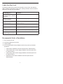
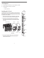
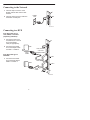
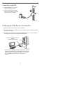
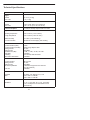
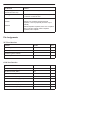
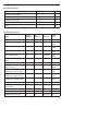
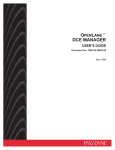
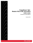
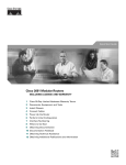
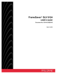
TM
9161 Single T1 Network Access Module (NAM)
Installation Instructions
Document Number 9161-A2-GN10-40
December 1998
Product Documentation on the World Wide Web
We provide complete product documentation online. This lets you search the
documentation for specific topics and print only what you need, reducing the waste of
surplus printing. It also helps us maintain competitive prices for our products.
Complete documentation for this product is available at www.paradyne.com.
Select Service & Support → Technical Manuals → T1 Access Multiplexers.
Select the following document:
9161-A2-GH30
Model 916x/926x T1 Access Mux Technical Reference
To request a paper copy of a Paradyne document:
Within the U.S.A., call 1-800-PARADYNE (1-800-727-2396)
Outside the U.S.A., call 1-727-530-8623
Before You Begin
Make sure you have:
An operable T1 network connection
An async (VT100-compatible) terminal emulator
Housing and other associated hardware
Applicable cables
Package Checklist
Verify that your package contains the following:
T1 NAM and associated I/O card
Network Interface Cable (14 ft.)
V.35 Interconnect Cable (1 ft.)
DB9 COM Port Cable (14 ft.)
Affidavit Requirements for Connection to Digital Service
1
Safety Instructions
Please read the EMI warning and Important Safety Instructions in the Technical
Reference or in the installation document that you received with your housing.
! HANDLING PRECAUTIONS FOR STATIC-SENSITIVE DEVICES
This product is designed to protect sensitive components from
damage due to electrostatic discharge (ESD) during normal
operation. When performing installation procedures,
however, take proper static control precautions to
prevent damage to equipment. If you are not sure
of the proper static control precautions, contact
your nearest sales or service representative.
496-15149
Available Options
The following options are separately orderable:
RJ48C modular cable for network access (20 ft.)
RJ48H T1 mass termination cable (5 ft.) for connecting seven T1 NAMs to an M66
block
What Does a T1 NAM Do?
The T1 NAM acts as an interface between the T1 digital network and the customer
premises equipment, converting signals received from the DTE to bipolar signals that
can be transmitted over T1 and Fractional T1 lines. The T1 NAM also provides a
DSX-1 drop and insert port to allow DTEs supporting the DS1 signal format to share
the network T1 with other high-speed equipment, as well as two synchronous data
ports. Typical applications include:
Wide Area Networks (WANs)
Channel extension
Video teleconferencing
2
Cables You May Need
The following cables and connectors are specifically for this product. See Warranty,
Sales, and Service Information on page 15 for ordering information. See the Technical
Reference for all cable pin-out information.
If connecting to a . . .
You need a . . .
Terminal/printer (DB25
interface/connector – EIA-232
connection)
COM Port-to-Terminal/Printer cable (14 ft.)
PC (DB9 interface/connector – COM Port-to-PC cable (14 ft.)
EIA-232 connection)
DTE with a V.35
interface/connector
MS34 to DB25 adapter cable for each port: Port 1
and/or Port 2 (1 ft.)
DTE with a RS-449
interface/connector
DB37 to DB25 DTE adapter cable for each port:
Port 1 and/or Port 2 (1 ft.)
DTE with a V.11/X.21
interface/connector
DB15 to DB25 adapter cable for each port: Port 1
and/or Port 2 (1 ft.)
LAN Adapter
COM Port-to-LAN Adapter cable (14 ft.)
Modem (8-pin
modular-to-DB25 connector)
Modem cable
Recommended Order of Installation
1. First, install the I/O card.
2. Connect all cables into the I/O card.
3. Install the NAM.
4. Go to the appropriate housing installation document for power-up verification
procedures:
— 2-Slot Housing Installation Instructions (Document No. 9000-A2-GN15)
— 5-Slot Housing with AC Power Supply Installation Instructions (Document
No. 9000-A2-GN16)
— 5-Slot Housing with DC Power Supply Installation Instructions (Document
No. 9000-A2-GN1C)
— 9000 Series Access Carrier Installation Instructions (Document No.
9000-A2-GN1D)
3
Tools Required
A small Phillips screwdriver (#1 or #2) to install the T1 NAM
A small, flat-blade screwdriver to install the:
— I/O card
— Cable connections
NAM
Rear Panel
Installing the I/O Card
The NAM’s I/O card provides the COM port, network, DSX and
DTE connections. The I/O card inserts directly behind the NAM
that it supports. Slot numbers are identical (in this case, Slot 01)
to facilitate correct installation.
SI
T1NGL
NA E
M
N
ET
1. Remove the I/O card from the shipping box. Handle only
by the top and bottom edges to avoid damaging the card.
2. At the rear of the housing, align the I/O card with the
upper and lower tracks of the slot. Push gently towards
the midplane until it stops and you cannot push the card
any further.
Access Carrier
5-Slot
2-Slot
NET
DBM
DB
M
(For
Future
Use)
DSX
DS
X
Port 1
PO
RT
1
Port 2
Screws
PO
RT
Screws
Screws
Rear View
3. There are two captive screws on the I/O card. Using a
screwdriver, alternately tighten each screw until the
screws are all the way in.
4
97-15748a
CO
M
2
COM
98-15050-03
Connecting to the Network
1. Insert the 8-pin connector on the
RJ48C network cable into the NET
interface.
SI
T1NGL
NA E
M
NE
T
RJ48C
Jack
2. Insert the other end of the cable into
the RJ48C modular jack.
NET
DB
M
DS
X
98-15053-02
Connecting to a DTE
If the DTE cable type is
V.35, RS449, or V.11/X.21
(separately orderable):
1. Connect the plug to the
V.35, RS449, or V.11/X.21
end of the adapter
cable (as appropriate).
SI
T1NGL
NA E
M
NE
T
DTE
2. Connect the EIA 530A
end of the adapter cable
to PORT 1 or PORT 2.
If the DTE cable type is
EIA-530A:
1. Connect the EIA-530A
end of the DTE cable to
PORT 1 or PORT 2.
DB
M
V.35, RS-449,
V.11/X.21
Adapter Cable
DTE
Cable
DS
X
Port 1
PO
RT
1
DTE
Port 2
PO
RT
DTE
Cable
2
CO
M
98-15054-02
5
Connecting to the DSX
SI
T1NGL
NA E
M
1. Insert the DB15 end of the DSX
cable into the DSX interface.
2. Insert the other end of the cable
into the CPE (Customer Premises
Equipment, such as a PBX).
NE
T
DB
M
DSX
PBX
DS
X
PO
RT
1
98-15055-02
Connecting the COM Port to a User Interface
1. Insert the 8-pin end of the cable into the COM port.
2. Insert the other end of the cable into the user interface (VT100-compatible terminal
emulation) connector.
3. Press Return on the keyboard to display the Main Menu. If you need to configure
for other than a direct link, see the Technical Reference.
COM Port-to-Terminal/Printer
Cable or
COM Port-to-PC Cable
COM
PO
RT
*
2
CO
M
496-15052-01
* Set the speed of the async (VT100-compatible) terminal so
it matches the NAM's factory-loaded data rate of 19.2 kbps,
character length set to 8, parity set to None, and stop bits
set to 1. The flow control should be set to None or
Hardware.
6
Installing the T1 NAM
In both the 2- and the 5-slot housings, the NAM is always installed in Slot 01. The NAM
can be installed in any slot in the access carrier.
! WARNING:
Do NOT remove any jumpers located on the battery. To do so can cause
non-volatile memory loss. Should a jumper become separated from the
battery, contact your service representative immediately.
CAUTION:
Be sure that you install the NAM in the correct slot so that it mates with its
matching I/O card. Otherwise, you could damage your card.
1. Remove the housing’s bezel, if applicable. See the housing installation instructions
for information.
2. Remove the NAM from the shipping box. Handle only by the top and bottom edges
to avoid damaging the card.
3. At the front of the housing, align the NAM with the upper and lower tracks of
the appropriate slot.
2-Slot
Ejector
Latches
5-Slot
Access Carrier
Ejector
Latches
Ejector
Latches
Front View
98-15750-01
4. Slide into the tracks until the NAM seats with the midplane connectors. Be careful
not to force the card or bend any pins.
5. Close both the upper and lower ejector latches on the housing to lock in place,
then tighten the captive screws on the ejector latches.
6. Replace the housing’s bezel, if applicable.
7
Removing/Replacing a Card
Card removal procedures differ, depending on whether you are removing the card from
the front or rear of the housing.
If you are removing the . . .
Then go to . . .
NAM
Removing/Replacing the NAM.
I/O card
Removing/Replacing the I/O Card.
Removing/Replacing the NAM
1. Remove the housing’s bezel, if applicable. See the housing installation instructions
for information.
2. Remove the captive screws from the ejector latches on front of the housing.
3. Press open the ejector latches to disengage the card.
4. Supporting the card by its edges, pull straight out until the card clears the housing.
5. Align the replacement card with the upper and lower tracks of the slot. Slide
forward until the NAM seats. Be careful not to force or bend any pins.
6. Close both the upper and lower ejector latches on the housing to lock in place,
then tighten the captive screws.
7. Replace the housing’s bezel, if applicable.
Removing/Replacing the I/O Card
1. Remove the NAM from the housing (see Removing/Replacing the NAM ).
2. Remove the network, DSX-1, DTE, and COM port cables from the I/O card (if
applicable).
3. Using a screwdriver, loosen the upper and lower screws fastening the card to the
housing’s frame.
4. Gently pull the I/O card away from the midplane until it clears the housing.
5. Align the replacement I/O card with the upper and lower tracks of the slot. Push
gently towards the midplane until it stops and you cannot push the card any further.
6. Alternately tighten each captive screw until the screws are all the way in.
7. Reattach the cables as appropriate.
8. Reinstall the NAM.
Power-Up
Go to your housing instructions to perform power-up, if needed. The housing
instructions also contain troubleshooting information.
8
Front Panel LEDs and Test Jacks
The T1 NAM has 12 LED (light-emitting diode) status indicators and four sets of test
jacks.
Test Jacks
The NAM contains four sets of test jacks. Use these for:
IN
NET
OU
T
Monitoring and testing towards the Network 1 interface
carrier
Monitoring and testing towards the Network 2 interface
carrier
IN
DSX
OU
T
Test
Jacks
IN
NET MON
Refer to Troubleshooting and Maintenance in the Technical
Reference for more information on the test jacks.
OU
T
IN
DSX MON
General Status LEDs
OU
T
9161
OK
Label Indication
AL
OK
M
TS
T
BK
P
Color
Power and Green
Operational
Status
SIG
NETWORK
AL
M
LEDs
SIG
DSX
OO
F
CYCLING – The unit is in
Minimum mode.
Requires an FTP
download.
AL
M
1–
PORT
2–
ON – NAM has power
and is
operational.
OFF – NAM is in a
power-up
self-test, or there
is a failure.
OO
F
What It Means
OK
OK
ALM
496-15051
System
Failure/
Self-Test
Red
ON – NAM has just
been reset, or an
error or fault has
been detected.
OFF – No failures have
been detected.
TST
Test Mode
Yellow
ON – Loopback or test
pattern in
progress,
initiated locally,
remotely, or from
the network.
OFF – No tests are
active.
BKP
Backup
9
Yellow
Not supported. Remains
off except during a Lamp
Test.
Network and DSX Interface LEDs
Label
Indication
Color
What It Means
SIG
Signal
Green
ON – A recoverable signal is present on
the network/DSX interface.
OFF – The signal cannot be recovered
from the network/DSX interface. An
LOS condition exists.
OOF
Out of Frame
Yellow
ON – At least one OOF was detected
during the sampling period.
OFF – No OOFs were detected during the
sampling period.
ALM
Alarm
Yellow
ON – An alarm condition is present on the
network/DSX interface.
Current alarm conditions:
Loss of Signal ( LOS )
Loss of Frame (LOF)
Excessive Error Rate (EER)
Yellow Alarm
Alarm Indication Signal (AIS)
OFF – No alarm condition is present on
the network/DSX interface.
Port 1 and Port 2 LEDs
Label
Indication
Color
What It Means
1-OK
2-OK
Operational
Status
Green
ON – The interchange circuits for the port
are in the correct state to transmit
and receive data.
OFF – The port is idle. Occurs if the port is
disabled, if an EDL Out of Frame or
EER condition is present, if a DCLB
is active, or if the port is configured
to monitor DTR and/or RTS and the
lead(s) is not asserted.
10
Troubleshooting
Symptom
Possible Cause
Solutions
No power, or none of the
system LEDs are lit.
For DC power source, DC
power is not present.
Check the DC power
source.
For AC power source, the
wall receptacle has no
power, or the housing’s
power cord is not securely
plugged into the wall
receptacle or the back of
tthe
e housing.
ous g
1. Check the wall
receptacle power by
plugging in some
equipment that is known
to be working.
2. Check that the power
cord is securely attached
at both ends.
3. Check the circuit
breaker.
Power-Up Self-Test fails.
Only Alarm LED is on
after power-up.
LED is burned out.
Run the Lamp Test. If the
LED in question does not
flash with the other LEDs,
then contact your service
representative.
The NAM has detected an
internal hardware failure.
1. Reset the NAM and try
again (see the Technical
Reference).
2. Contact your service
representative.
Cannot access the NAM
or the user interface.
Login or password is
incorrect, COM port is
misconfigured, or the NAM
otherwise configured so it
prevents access.
1. Reset the NAM (see the
Technical Reference).
Device Fail appears on
the System Health and
Status screen.
The NAM detects an
internal hardware failure.
Record the 8-digit code
from the System Health
and Status screen, then
contact your service
representative.
Not receiving data at
DTE or DSX-1 interface.
Not cross-connected to the
correct timeslot(s).
Verify cross connections
using the Cross Connect
configuration option.
11
2. Contact your service
representative.
Technical Specifications
Specification
Criteria
Weight
T1 NAM
T1 I/O card
1 lb. 2 oz. (.51 kg)
6 oz. (.17 kg)
Size
T1 NAM
T1 I/O card
11.58″ x 8.00″ (29.41 cm x 20.32 cm)
2.90″ x 10.15″ (7.37 cm x 25.78 cm)
Power Consumption
9.4 watts, 0.78 amps input current at 12 volts
Physical Environment
Operating temperature
35° F to 122° F ( 1.7° C to 50° C )
Storage temperature
–4° F to 158° F (– 20° C to 70° C )
Relative humidity
5% to 85% ( noncondensing )
Shock and vibration
Withstands normal shipping and handling
Network T1 Interface
Physical Interface (USA)
Physical Interface (Canada)
Framing Format
Coding Format
Line Build-Out (LBO)
ANSI PRM
Bit Stuffing
Yellow Alarm Generation
RJ48C
CA81A using adapter cable
D4, ESF
AMI, B8ZS
0.0 dB, –7.5 dB, –15 dB, –22.5 dB
Selectable
FCC Part 68, AT&T TR 62411
Selectable
DSX-1 Interface
Physical Interface
Framing Format
Coding Format
DTE Line Equalization
Send AIS
DB15 socket
D4, ESF
AMI, B8ZS
5 selectable ranges from 0 to 655 feet
(0 to 196.5 meters)
Selectable
DTE Ports/Interfaces
Standards
Rates
EIA-530A, V.35, RS-449, V.11, X.21
Nx64 – 64K to 1.536 Mb
Nx56 – 56K to 1.344 Mb
COM Port/Interface
Data Rates
9.6, 14.4, 19.2, 28.8, 38.4 , 57.6, 115.2 kbps
57.6, 115.2 kbps are recommended for FTP
download only
12
Specification
Criteria
DBM (Backup) connector
(reserved for future use)
One 8-position modular keyed USOC RJ45 jack
Clocking Sources
T1 network interface, any port, internal clock, DSX-1
T1 interface or external clock
Loopbacks
Standard
Additional
Network Line Loopback, Network Payload
Loopback, V.54 Loop 2 (DCLB) and V.54 Loop 3
(DTPLB)
Network Repeater Loopback, DSX-1 Line Loopback
DSX-1 Payload Loopback, DSX-1 Repeater
Loopback, DTE Loopback
Pin Assignments
NET Port/Interface
Function
Circuit
Pin #
Receive ring from the network
R1
1
Receive tip from the network
T1
2
Transmit ring to the network
R
4
Transmit tip to the network
T
5
Signal
Direction
Pin #
DCE Transmit Clock ( TXC )
Out
1
DCE Receive Data ( RXD )
Out
2
Signal Ground ( SG )
—
3
DCE Transmit Data ( TXD )
In
4
DCE Data Terminal Ready ( DTR )
In
5
DCE Carrier Detect ( CD )
Out
6
DCE Request to Send ( RTS )
In
7
DCE Receive Clock ( RXC )
Out
8
COM Port/Interface
13
DSX Port/Interface
Function
Circuit
Pin #
Receive tip from the DTE
T1
1
Receive ring from the DTE
R1
9
Transmit tip to the DTE
T
3
Transmit ring to the DTE
R
11
Shield
–
2,4
DTE Ports/Interfaces
Signal
Circuit
ITU/
Mnemonic CCITT #
Direction
25-Pin
Pin #
Shield
—
—
—
1
Transmitted Data ( TXD )
BA
103
To DCE
2 (A)
14 (B)
Received Data ( RXD )
BB
104
From DCE
3 (A)
16 (B)
Request to Send ( RTS )
CA
105
To DCE
4 (A)
19 (B)
Clear to Send ( CTS )
CB
106
From DCE
5 (A)
13 (B)
Data Set (or DCE ) Ready
( DSR )
CC
107
From DCE
6
Signal Ground/Common ( SG )
AB
102A
—
7
Received Line Signal Detector CF
( RLSD or LSD )
109
From DCE
8 (A)
10 (B)
Transmit Signal Element
Timing (TXC – DTE Source)
DA
113
To DCE
11 (B)
24 (A)
Transmitter Signal Element
Timing ( TXC – DCE Source)
DB
114
From DCE
12 (B)
15 (A)
Receiver Signal Element
Timing ( RXC – DCE Source )
DD
115
From DCE
17 (A)
9 (B)
Local Loopback ( LL )
LL
141
To DCE
18
Data Terminal (or DTE )
Ready ( DTR )
CD
108/1, /2
To DCE
20
Remote Loopback ( RL )
RL
140
To DCE
21
Signal Common
AC
102B
—
22, 23
Test Mode Indicator ( TM )
TM
142
From DCE
25
14
Warranty, Sales, and Service Information
Contact your local sales representative, service representative, or distributor directly for
any help needed. For additional information concerning warranty, sales, service, repair,
installation, documentation, training, distributor locations, or Paradyne worldwide office
locations, use one of the following methods:
H
Via the Internet: Visit the Paradyne World Wide Web site at
http://www.paradyne.com
H
Via Telephone: Call our automated call system to receive current information via
fax or to speak with a company representative.
— Within the U.S.A., call 1-800-870-2221
— Outside the U.S.A., call 1-727-530-2340
Document Feedback
We welcome your comments and suggestions about this document. Please mail them
to Technical Publications, Paradyne Corporation, 8545 126th Ave. N., Largo, FL 33773,
or send e-mail to [email protected]. Include the number and title of this
document in your correspondence. Please include your name and phone number if you
are willing to provide additional clarification.
Trademarks
All products and services mentioned herein are the trademarks, service marks,
registered trademarks or registered service marks of their respective owners.
Copyright E 1998 Paradyne Corporation
15