1
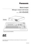
Operating Instructions
Multi-format Live Switcher
Model No.
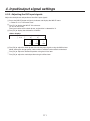
POWER1
OFF
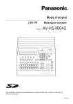
AV-HS450N
ON
POWER1
Mainframe
[AV-HS450U1N]
ALARM1
POWER2
OFF
ON
POWER2
ALARM2
Multi-format
Live Switcher
AV-HS450
Multi-format Live Switcher AV-HS450
POWER
ALARM
Control panel [AV-HS450C1N]
Before operating this product, please read the instructions carefully and save this manual for
future use.
Printed in Japan
3TR006327AAC
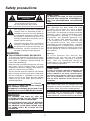
Safety precautions
CAUTION:
CAUTION
TO REDUCE THE RISK OF FIRE OR SHOCK
HAZARD AND ANNOYING INTERFERENCE,
USE THE RECOMMENDED ACCESSORIES
ONLY.
RISK OF ELECTRIC SHOCK
DO NOT OPEN
CAUTION: TO REDUCE THE RISK OF ELECTRIC SHOCK,
DO NOT REMOVE COVER (OR BACK).
NO USER SERVICEABLE PARTS INSIDE.
REFER TO SERVICING TO QUALIFIED SERVICE PERSONNEL.
FCC Note:
This equipment has been tested and found
to comply with the limits for a class A digital
device, pursuant to Part 15 of the FCC Rules.
These limits are designed to provide reasonable
protection against harmful interference when
the equipment is operated in a commercial
environment. This equipment generates, uses,
and can radiate radio frequency energy, and
if not installed and used in accordance with
the instruction manual, may cause harmful
interference to radio communications. Operation
of this equipment in a residential area is likely to
cause harmful interference in which case the user
will be required to correct the interference at his
own expense.
The lightning flash with arrowhead
symbol, within an equilateral triangle, is
intended to alert the user to the presence
of uninsulated “dangerous voltage” within
the product’s enclosure that may be of
sufficient magnitude to constitute a risk of
electric shock to persons.
The exclamation point within an equilateral
triangle is intended to alert the user to
the presence of important operating and
maintenance (service) instructions in the
literature accompanying the appliance.
WARNING:
Warning:
To assure continued FCC emission limit
compliance, the user must use only shielded
interface cables when connecting to external
units. Also, any unauthorized changes or
modifications to this equipment could void the
user’s authority to operate it.
THIS APPARATUS MUST BE EARTHED
To ensure safe operation, the three-pin plug must
be inserted only into a standard three-pin power
point which is effectively earthed through the
normal household wiring.
Extension cords used with the apparatus must have
three cores and be correctly wired to provide
connection to the earth. Wrongly wired extension
cords are a major cause of fatalities.
The fact that the apparatus operates satisfactorily
does not imply that the power point is earthed or
that the installation is completely safe. For your
safety, if you are in any doubt about the effective
earthing of the power point, please consult a
qualified electrician.
CAUTION:
In order to maintain adequate ventilation, do
not install or place this unit in a bookcase,
built-in cabinet or any other confined space.
To prevent risk of electric shock or fire hazard
due to overheating, ensure that curtains
and any other materials do not obstruct the
ventilation.
For CANADA
This class A digital apparatus complies
with Canadian ICES-003.
Cet appareil numérique de la classe A est
conforme à la norme NMB-003 du Canada.
The socket outlet shall be installed near the
equipment and easily accessible or the mains plug
or a power switch shall remain readily operable.
A warning that an apparatus with CLASS I
construction shall be connected to a MAINS
socket outlet with a protective earthing connection.
WARNING:
• TO REDUCE THE RISK OF FIRE OR
ELECTRIC SHOCK, DO NOT EXPOSE THIS
APPARATUS TO RAIN OR MOISTURE.
• THE APPARATUS SHALL NOT BE EXPOSED
TO DRIPPING OR SPLASHING AND THAT
NO OBJECTS FILLED WITH LIQUIDS, SUCH
AS VASES, SHALL BE PLACED ON THE
APPARATUS.
indicates safety information.
2
Safety precautions
IMPORTANT SAFETY INSTRUCTIONS
Read these operating instructions carefully before using the unit. Follow the safety instructions on the
unit and the applicable safety instructions listed below. Keep these operating instructions handy for future
reference.
10) Protect the power cord form being walked on or
pinched particularly at plugs, convenience
receptacles, and the point where they exit from
the apparatus.
1) Read these instructions.
2) Keep these instructions.
3) Heed all warnings.
11) Only use attachments/accessories specified by
the manufacturer.
4) Follow all instructions.
5) Do not use this apparatus near water.
12) Use only with the cart, stand,
tripod, bracket, or table specified
by the manufacturer, or sold with
the apparatus. When a cart is
used, use caution when moving
the cart/apparatus combination to
avoid injury from tip-over.
6) Clean only with dry cloth.
7) Do not block any ventilation openings. Install
in accordance with the manufacturer’s
instructions.
8) Do not install near any heat sources
such as radiators, heat registers, stoves, or
other apparatus (including amplifiers) that
produce heat.
13) Unplug this apparatus during lightning storms
or when unused for long periods of time.
14) Refer all servicing to qualified service
personnel. Servicing is required when the
apparatus has been damaged in any way, such
as power-supply cord or plug is damaged,
liquid has been spilled or objects have fallen
into the apparatus, the apparatus has been
exposed to rain or moisture, does not operate
normally, or has been dropped.
9) Do not defeat the safety purpose of the
polarized or grounding-type plug. A polarized
plug has two blades with one wider than the
other. A grounding-type plug has two blades
and a third grounding prong. The wide blade or
the third prong are provided for your safety. If
the provided plug does not fit into your outlet,
consult an electrician for replacement of the
obsolete outlet.
indicates safety information.
<For USA-California Only>
This product contains a CR Coin Cell Lithium Battery which contains Perchlorate Material – special handling
may apply.
See www.dtsc.ca/gov/hazardouswaste.perchlorate.
3
Contents
Description ................................................ 7
3. Basic operations ................................. 33
Features..................................................... 7
3-1. Background transition ......................................33
3-1-1. Selecting the bus ......................................33
Configuration ............................................ 9
3-1-2. Selecting the bus using the
SHIFT function .....................................33
Accessories .............................................. 9
3-1-3. Selecting the bus mode ............................36
Precautions for use ................................ 10
3-1-4. Selecting the transition mode ...................37
Trademarks and
Registered Trademarks ..................... 11
3-1-5. Manual transition (using the fader lever) ...37
Disclaimer of Warranty ........................... 11
3-1-7. Cut transition.............................................37
1. Installation ........................................... 12
3-2. IMAGE .............................................................38
3-1-6. Auto transition ...........................................37
3-2-1. Setting the IMAGE effects.........................38
1-1. Installing the control panel...............................12
3-2-2. Executing the IMAGE effect ......................39
1-2. Installing the mainframe ..................................13
3-3. Wipe ................................................................40
1-3. How to install the option boards ......................14
3-3-1. Selecting the wipe pattern ........................40
1-4. Connections ....................................................16
3-3-2. Selecting the background for the
3D2 pattern page .................................42
1-4-1. Block diagram ...........................................16
1-4-2. Connections when implementing gen-lock
(frame synchronizer OFF) ....................17
3-3-3. Selecting the wipe direction ......................42
1-4-3. Connections when not implementing genlock (frame synchronizer ON) ..............18
3-3-5. Setting the wipe start position...................44
2. Functions in each area ....................... 19
3-4. Key ..................................................................47
2-1. Control panel ...................................................19
3-4-1. Selecting the key type ...............................48
2-1-1. Crosspoint area ........................................20
3-4-2. Selecting the key material.........................49
2-1-2. Wipe pattern/memory area .......................21
3-4-3. Key transitions ..........................................50
2-1-3. User button area .......................................22
3-4-4. Key preview...............................................51
2-1-4. Transition area ..........................................22
2-1-5. LCD menu area ........................................25
3-4-5. Adjusting the luminance key
and linear key .......................................52
2-1-6. Positioner area ..........................................27
3-4-6. Adjusting the chroma key .........................53
2-1-7. SD memory card area ..............................28
3-4-7. Key decorations ........................................61
2-1-8. Rear panel connections area ....................29
3-4-8. Masking the key signals ............................62
3-3-4. Wipe decorations (border, soft effect) .......43
3-3-6. Modifying wipe ..........................................45
3-4-9. Flying key ..................................................63
2-2. Mainframe .......................................................30
2-2-1. Front panel ................................................30
3-5. PinP (picture in picture) ...................................64
2-2-2. Rear panel connections area ....................31
3-5-1. Selecting the PinP channel
and material .........................................64
3-5-2. Selecting Shape........................................65
3-5-3. PinP preview .............................................65
3-5-4. PinP transitions .........................................66
3-5-5. PinP adjustments ......................................66
3-5-6. Linking PinP1 and PinP2 ..........................68
3-5-7. PinP decorations.......................................69
3-5-8. Trimming settings ......................................70
4
Contents
3-6. DSK (downstream key)....................................71
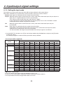
4. Input/output signal settings............... 96
3-6-1. Selecting the DSK type .............................71
4-1. Input signal settings.........................................96
3-6-2. Selecting the DSK channel and
DSK fill material ....................................73
4-1-1. Setting the frame synchronizer .................97
4-1-2. Setting the input mode ..............................98
3-6-3. DSK transitions .........................................74
4-1-3. Freezing the input signals .........................99
3-6-4. DSK preview .............................................74
4-1-4. Color corrector ........................................100
3-6-5. DSK adjustments ......................................75
4-1-5. Setting the up-converter .........................104
3-6-6. DSK decorations .......................................76
4-1-6. Setting the analog input gain (option) .....105
3-6-7. Masking the DSK signals ..........................77
3-7. FTB (fade to black) ..........................................78
4-1-7. Setting the analog composite input signals
(option) ...............................................106
3-8. Internal color signals .......................................79
4-2. Setting the DVI input signals (option) ............107
3-8-1. Setting the color background ....................79
4-2-1. Setting the DVI input signals ...................107
3-9. Switching the AUX output ................................80
4-2-2. Adjusting the DVI input signals ...............111
3-9-1. Selecting the AUX output materials ..........80
4-3. Setting the output signals ..............................112
3-9-2. AUX1 transitions .......................................81
4-3-1. Assigning the output signals ...................113
3-9-3. Setting enable/disable for the
AUX1 transition.....................................82
3-10. Memory .........................................................83
4-4. Setting the DVI output signals
(OUT5 and OUT6 standard outputs and
options) .....................................................115
3-10-1. Memory registration and recall items ......84
4-5. Setting the down-converter (option) ..............117
3-10-2. Storing the settings in the
memory (Store) ...................................85
4-6. Setting the sync signals.................................118
3-10-3. Recalling the operations stored in the
memory (Recall)...................................86
4-7. Adjusting the output signal phase .................119
3-10-4. Deleting the operations stored in the
memory (Delete) ..................................87
4-8-1. Setting the screen layout ........................123
4-8. Setting the multi view display ........................123
4-8-2. Setting the split frame and characters ....125
3-10-5. Effect dissolve .........................................88
4-8-3. Setting the tally displays .........................126
3-11. Frame memories ...........................................89
4-8-4. Changing the material names .................127
3-11-1. Transferring images from the AUX bus ...89
4-8-5. High-resolution multi view mode .............128
3-11-2. Saving Images in Flash Memory ............90
4-9. Setting the on-screen display (OSD) .............129
3-12. SD memory cards .........................................91
4-10. Setting the ancillary data .............................130
3-12-1. Initializing the SD memory cards ............92
3-12-2. Saving data on SD memory cards ..........93
3-12-3. Loading data from SD memory cards .....94
3-12-4. Deleting files on SD memory cards ........95
3-12-5. Displaying the SD memory card
information...........................................95
5
Contents
5. System settings ................................ 131
6. External interfaces ........................... 154
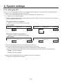
5-1. Selecting the video format .............................131
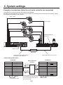
6-1. Connecting the control panel
and mainframe ..........................................154
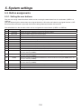
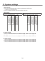
5-2. Setting the crosspoints ..................................132
5-2-1. Assigning signals to the crosspoints .......132
6-2. Mainframe .....................................................154
5-2-2. Setting the crosspoint switching .............134
6-2-1. LAN .........................................................154
6-2-2. EDITOR ..................................................155
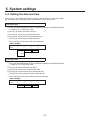
5-3. Button assignments .......................................135
6-2-3. COM .......................................................155
5-3-1. Setting the user buttons ..........................135
6-2-4. TALLY/GPI...............................................156
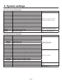
5-4. Setting the date and time ..............................137
6-3. Control panel .................................................157
5-5. Network settings ............................................138
6-3-1. TALLY/GPI...............................................157
5-6. Other settings ................................................139
7. Image transmission functions ......... 158
5-7. External device control ..................................140
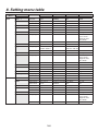
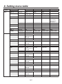
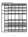
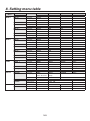
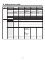
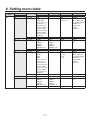
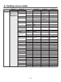
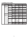
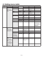
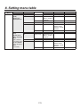
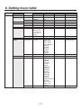
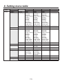
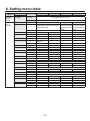
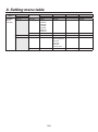
8. Setting menu table............................ 163
5-7-1. Enable/Disable Setting for Control of
External Devices ................................140
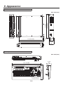
9. Appearance ....................................... 181
5-7-2. Editor control...........................................141
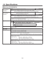
10. Specifications ................................. 182
5-7-3. Setting the GPI .......................................142
Appendix (glossary) ............................. 187
5-7-4. Camera control .......................................144
5-8. Status displays ..............................................151
5-8-1. Alarm status displays ..............................151
5-8-2. Alarm message.......................................151
5-8-3. Displaying the version information and
option information ................................152
5-9. Initialization....................................................153
5-9-1. Initializing Setting Data ...........................153
5-9-2. Initializing Fader ......................................153
6
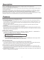
Description
This is a 1 ME digital video switcher which supports a multiple number of HD and SD formats.
It consists of a mainframe and control panel.
Despite its compact dimensions of 2RU, the mainframe comes with 16 inputs and four outputs for SDI under the
standard specifications.
It also supports two DVI outputs, and its video effects of one key line, two DSK lines, two PinP lines, two DVE
(BKGD) lines, one DVE (key) line and two multi view lines enable video productions in a wide variety of forms.
Incorporated in the switcher’s inputs are a frame synchronizer, up-converter and color corrector.
When the option boards are installed, a wider variety of input/output formats including analog composite, analog
component and DVI can be accommodated so that systems can be constructed flexibly.
Features
Compact design, wide variety of input/output signals
The mainframe, despite its compact dimensions of 2RU, comes with a wide variety of input/output facilities in
the standard configuration.
As input facilities, a total of 16 HD/SD-SDI signal lines are supported under the standard specifications, and a
frame synchronizer is incorporated for all the inputs. Also incorporated are four up-converter signal lines and
eight color corrector signal lines.
The output facilities include four HD/SD-SDI signal lines and two DVI-D signal lines under the standard
specifications.
Two option slots each for input/output applications are provided.
When two option boards for input applications are installed, the maximum number of input signal lines can be
expanded to 20; similarly, when two option boards for output applications are installed, the maximum number of
output signal lines can be increased to 10.
Multiple formats supported
The signal formats supported include HD formats (1080/59.94i, 1080/50i, 1080/24PsF 1, 1080/23.98PsF 1,
720/59.94p and 720/50p), SD formats (480/59.94i and 576/50i) and DVI 2.
1: The following option boards are not supported:
AV-HS04M1, AV-HS04M2, AV-HS04M3, AV-HS04M4, AV-HS04M5,
AV-HS04M6, AV-HS04M7
2: The standard DVI output is the DVI-D signal output.
The AV-HS04M3 option board supports DVI-I signal input, the AV-HS04M8 option board supports DVI-D
signal input, and the AV-HS04M5 supports DVI-I signal output.
Multi view display function
Two multi view display function lines are provided under the standard specifications.
It is possible to divide up to 20 lines of video including program video (PGM), preview video (PVW) and input
video signals between two screens and display them at the same time on two monitors.
Frame synchronizer system and external synchronization system supported
A high-performance 10-bit frame synchronizer is incorporated for all the inputs so that asynchronous video
signals can be input. By using the black burst (BB) output, it is possible to construct a system referenced to the
synchronization of the switcher.
A genlock function is provided so that external synchronization systems using external sync signals (BB or TRI
signals) as a reference are also supported.
7
Features
Many different effect functions incorporated
Along with the standard wipe, mix and cut functions, the switcher can provide size reduction, slide and other
DVE transitions.
DVE transitions using the 2-screen push-out effect and other 2-channel functions are possible.
The unit comes with luminance keys and chroma keys provided as keyers as well as specialized hardware in
the form of two DSK lines and two PinP lines as a standard option.
AUX1 is equipped with a mix transition function.
This enables MIX transitions with the material selected next, allowing for a flexible system construction.
High-quality chroma keys using Primatte® algorithms
The Primatte® algorithm, which has proven to be very popular in many non-linear editors as a plug-in software,
has been put to practical use in a linear editing system for the chroma keys. High chroma key image quality can
be achieved through some simple operations.
Primatte® is a registered trademark of IMAGICA DIGIX Inc.
The copyrights of Primatte® belong to IMAGICA DIGIX Inc.
The patents for Primatte® belong to IMAGICA DIGIX Inc.
SDHC memory cards supported
Still image data (BMP, JPEG) can be imported from SDHC memory cards into the unit’s frame memories for use
as background images or key materials.
In addition, the images and setting data in the unit’s frame memories can be stored on the SDHC memory
cards.
SDHC Logo is a trademark.
Pan-tilt head system (pan-tilt head and convertible camera) control supported
Using the COM connector, a Panasonic pan-tilt head system (with pan, tilt, zoom, focus and preset functions)
can be controlled.
When a controller is used, up to five pan-tilt head systems can be controlled.
Camera menu operations can also be performed.
Controllers supported
AW-RP555N, AW-RP655N
Pan-tilt heads supported
AW-PH400P, AW-PH405N, AW-PH360N
Camera supported
AW-HE100N
Redundant power supply
Under the standard specifications, a redundant power supply is provided so that live operations can be
undertaken with complete peace of mind.
Simple operability
Live transmissions can be delivered speedily thanks to the 16 crosspoint buttons and pattern selection buttons
and other controls on the panel with its simple layout that enables various functions to be operated directly.
Preset-like operations are performed using menus appearing on the unit’s LCD display or on the on-screen
displays.
8
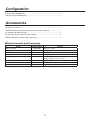
Configuration
Mainframe [AV-HS450U1N] .............................................................................. 1
Control panel [AV-HS450C1N] .......................................................................... 1
Accessories
Operating instructions ....................................................................................... 1
CD-ROM (Operating instructions/Image transmission software) ...................... 1
AC adapters (for control panel) ......................................................................... 2
Power cords (for mainframe and AC adapter) .................................................. 4
CAT5E cable (STP, straight cable, 10 m long) .................................................. 1
Optional boards (sold separately)
Board
Model number
Function
SDI Input Board
AV-HS04M1
SDI input 2 lines
Analog Input Board
AV-HS04M2
Analog component input 2 lines
DVI Input Board
AV-HS04M3
DVI-I input 2 lines
Analog Output Board
AV-HS04M4
Analog component output 2 lines
DVI/Analog Output Board
AV-HS04M5
DVI-I output 1 line
Analog component output 1 line
Analog Composite Input Board
AV-HS04M6
Analog composite input 2 lines
SDI Output Board
AV-HS04M7
SDI output 2 lines
Full-HD DVI Input Board
AV-HS04M8
DVI-D input 2 line
Option boards are installed in the two input/output option slots (slot A, slot B).
9
Precautions for use
Handle carefully.
Do not drop the product, or subject it to strong shock or vibration.
Do not carry or move the product by the fader lever. This is important to prevent trouble.
Use the product in an ambient temperature of 32 °F to 104 °F (0 °C to 40 °C).
Avoid using the product at a cold place below 32 °F (0 °C) or at a hot place above 104 °F (40 °C) because
extremely low or high temperature will adversely affect the parts inside.
Power off before connecting or disconnecting cables.
Before plugging or unplugging the cables, be sure to switch power off.
Avoid humidity and dust.
Avoid using the product at a humid, dusty place because much humidity and dust will cause damage to the
parts inside.
Maintenance
Wipe the product using a dry cloth. To remove stubborn dirt, dip a cloth into a diluted solution of kitchen
detergent (neutral), wring it out well, and wipe the product gently. Then, after wiping the product with a moist
cloth, wipe it again with a dry cloth.
Caution
• Avoid using benzine, paint thinners and other volatile fluids.
• If a chemical cleaning cloth is to be used, carefully read through the precautions for its use.
Precaution to be observed during production
This product’s image switching and image effect functions can be used to produce images which flicker rapidly
or images which change rapidly.
However, bear in mind when using these functions in production that the kinds of images produced may have
an adverse effect on the viewer’s physical well-being.
Handling the optional boards
Be absolutely sure to turn off the power of the product before installing or removing any of the optional boards.
Furthermore, when installing or removing the optional boards, take care not to hurt yourself on the edges and
metal parts of the boards.
When the product is to be discarded
When the product is to be discarded at the end of its service life, ask a specialized contractor to dispose of it
properly in order to protect the environment.
Concerning the consumable parts
Cooling fan:
This is a consumable part. As a general rule, replace it every 5 years or so (when the unit has been
operated for 15 hours a day).
Power supply unit:
This is a consumable part. As a general rule, replace it every 5 years or so (when the unit has been
operated for 15 hours a day).
The period when the consumable parts need to be replaced will differ depending on the operating conditions.
When the time comes to replace one of these parts, be absolutely sure to ask your dealer to do the job.
10
Precautions for use
Trademarks and Registered Trademarks
Microsoft and Windows are either registered trademarks or trademarks of Microsoft Corporation in the United
States and other countries.
Adobe and Reader are either registered trademarks or trademarks of Adobe Systems Incorporated in the
United States and/or other countries.
SDHC logo is a trademark.
Other names of companies and products contained in these operating instructions may be trademarks or
registered trademarks of their respective owners.
Disclaimer of Warranty
IN NO EVENT SHALL Panasonic Corporation BE LIABLE TO ANY PARTY OR ANY PERSON, EXCEPT FOR
REPLACEMENT OR REASONABLE MAINTENANCE OF THE PRODUCT, FOR THE CASES, INCLUDING BUT
NOT LIMITED TO BELOW:
ANY DAMAGE AND LOSS, INCLUDING WITHOUT LIMITATION, DIRECT OR INDIRECT, SPECIAL,
CONSEQUENTIAL OR EXEMPLARY, ARISING OUT OF OR RELATING TO THE PRODUCT;
PERSONAL INJURY OR ANY DAMAGE CAUSED BY INAPPROPRIATE USE OR NEGLIGENT
OPERATION OF THE USER;
UNAUTHORIZED DISASSEMBLE, REPAIR OR MODIFICATION OF THE PRODUCT BY THE USER;
INCONVENIENCE OR ANY LOSS ARISING WHEN IMAGES ARE NOT DISPLAYED, DUE TO ANY
REASON OR CAUSE INCLUDING ANY FAILURE OR PROBLEM OF THE PRODUCT;
ANY PROBLEM, CONSEQUENTIAL INCONVENIENCE, OR LOSS OR DAMAGE, ARISING OUT OF THE
SYSTEM COMBINED BY THE DEVICES OF THIRD PARTY;
INCONVENIENCE, DAMAGE, OR LOSS RESULTING FROM ACCIDENTS CAUSED BY AN INADEQUATE
INSTALLATION METHOD OR ANYTHING OTHER THAN A DEFECT IN THE PRODUCT;
LOSS OF REGISTERED DATA CAUSED BY ANY FAILURE.
ANY DAMAGE OR CLAIMS DUE TO LOSS OR LEAKAGE OF IMAGE DATA OR SETTING DATA SAVED
ON THIS UNIT OR ON AN SD CARD OR PC.
11
1. Installation
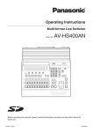
1-1. Installing the control panel
Follow the instructions set forth in “Safety precautions” and also observe the
cautionary items below.
Be absolutely sure to ask your dealer to do the jobs of installing and connecting the panel.
Connecting the power supply
Be absolutely sure to use only the power cord and AC adapter supplied with the
panel.
Be absolutely sure to connect the grounding terminal of the power cord to
ground.
Also connect the ground terminal (SIGNAL GND) at the rear of the panel to the
system ground.
If only one AC adapter is to be connected, place the dust-proof cap over the DC
power input socket that is not going to be used.
To prevent the DC plug from being disconnected, secure the cable of the AC
adapter to the cable clamp.
When the control panel is not going to be used for a prolonged period of time,
set its power switch to the “off” position to conserve power, and disconnect the
power plug.
Dust-proof cap
POWEROFF
LCD
RAST
CONT
12V
IN1 12V
IN2
ON
AME
NFR
MAI
Cable clamp
Handle the control panel carefully!
Dropping the control panel or subjecting it to strong impact or vibration may cause trouble and/or malfunctioning.
Do not allow any foreign objects to enter inside the control panel!
Allowing water, metal items, scraps of food or other foreign objects inside the control panel may cause a fire
and/or electric shocks.
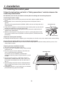
Choosing the best installation location
This unit is designed for indoor use only.
Install the unit on a sufficiently strong, stable and level
surface for use.
Ensure a space of at least 100 mm around the rear
vents to avoid obstructing ventilation.
In particular, ensure sufficient space between
ventilation and wiring when using mounted in a panel
or table.
Do not install the panel in a cold place where the
temperatures will drop below 32 °F (0 °C) or in a hot
place where the temperatures will rise above 104 °F
(40 °C).
Avoid installing the panel where it will be exposed to
direct sunlight or to the hot air that is blown out from
other products.
Installing the panel in a very humid, dusty or vibrationprone location may give rise to trouble.
12
Ventilation holes
Multi-format Live Switcher AV-HS450
POWER
ALARM
1. Installation
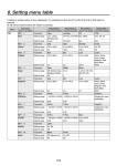
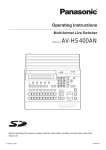
1-2. Installing the mainframe
Comply with the instructions set forth in “Safety precautions” and also observe
the cautionary items below.
Be absolutely sure to ask your dealer to do the jobs of installing and connecting the mainframe.
Connecting the power supply
Be absolutely sure to use the power cord supplied with the mainframe.
Be absolutely sure to connect the grounding terminal of the power cord to ground.
Handle the mainframe carefully!
Dropping the mainframe or subjecting it to strong impact or vibration may cause trouble and/or malfunctioning.
Do not allow any foreign objects to enter inside the mainframe!
Allowing water, metal items, scraps of food or other foreign objects inside the control panel may cause a fire
and/or electric shocks.
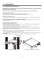
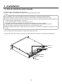
Choosing the best installation location
This unit is designed for indoor use only.
Mount the mainframe securely in a standard 19-inch rack (with a depth dimension of at least 600 mm) that
meets the EIA standard or its equivalent for use.
Install the mainframe securely using screws that are compatible with the rack.
Be absolutely sure to attach the support guides used to support the back part of the mainframe. (Provide
support guides that are compatible with the rack.)
Provide sufficient clearances from the area around the ventilation holes at the front and the cooling fan at the
back.
Do not install the mainframe in a cold place where the temperatures will drop below 32 °F (0 °C) or in a hot
place where the temperatures will rise above 104 °F (40 °C).
Avoid installing the mainframe where it will be exposed to direct sunlight or to the hot air that is blown out from
other products.
Installing the mainframe in a very humid, dusty or vibration-prone location may give rise to trouble.
Support guides
POWER1
OFF
ON
POWER1
ALARM1
POWER2
OFF
ON
POWER2
ALARM2
50
Multi-format
Live Switche
r AV-HS450
S4
-H
r AV
ER2
POW
WE
PO
R2 ON
2
RM
ALA
he
itc
F
OF
at
Live
Sw
rm
ti-fo
Mul
R1 ON
WE
PO
R1
WE
PO
1
RM
ALA
F
OF
Installation in a rack
Flow of air through the ventilation holes
13
1. Installation
1-3. How to install the option boards
The option boards are installed in the mainframe.
For details, refer to the operating instructions of the option board concerned.
Notes
Be absolutely sure to ask your dealer to do the job of installing or removing the option boards.
Before installing or removing an option board, turn off the power, and disconnect the power plug.
Before coming into physical contact with the option board, touch your hand to metal that has been grounded
to discharge the static electricity in your body.
A safe way to proceed is to wear an anti-static wrist strap.
The option board may be damaged if you touch the board with static still in your body.
Avoid damage to the option board by not dropping it or subjecting it to strong shocks or vibrations.
After removing an option board, be absolutely sure to attach the blank panel.
When installing or removing an option board, take care not to hurt yourself on the edges or metal parts of the
board.
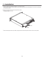
Turn off the power of the mainframe, and disconnect the power cord.
Loosen the two screws of SLOT A or SLOT B at the back of the mainframe, and remove the blank panel.
SLOT A
SLOT B
Blank panel
Screw
Screw
14
1. Installation
Align the option board with the guide rails, and insert it slowly.
Insert it until it will go no further. Take care not to exert excessive force while doing this since that may damage
the connector inside.
Mount the option board in place using the two screws.
Clamping torque: 0.7 N•m
I-D
DV
TS
PU
I IN
DV
I-D
DV
Screw
Screw
After connecting the necessary cables, plug the power cord into the power outlet, and turn on the power.
15
1. Installation
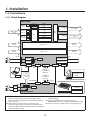
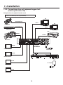
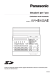
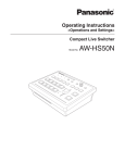
1-4. Connections
1-4-1. Block diagram
Mainframe
INPUT
1 to 8
INPUT (SDI)
1 to 16
INPUT
9 to 12
Black
ColorBGD
ColorBar
FMEM1 to 4
FS
BKGD
CUT, MIX, WIPE, DVE2
KEY
CUT, MIX, WIPE, DVE
FS
PinP1, 2
MIX
CC
DSK1, 2
MIX
MTX
OUTPUT (SDI)
1 to 4 (3)
OUTPUT
5, 6
OUTPUT (DVI-D)
5, 6
Output
MTX
FTB
AUX1 to 4
FS
INPUT
13 to 16 UC
CC
OUTPUT
1 to 4
MV1, 2
INPUT
A1, A2
Option slot A
OUTPUT
A1, A2
INPUT
B1, B2
Option slot B
OUTPUT
B1, B2
AC IN
REF
AC/DC
Power
REF IN/OUT (1)
AC/DC
REF OUT (2)
RJ45
LAN
(5)
RJ45
Dsub 50
PANEL
(4)
Dsub 9
TALLY/GPI
ALARM: 1
GPI-OUT: 31
GPI-IN: 8
PC
SD
memory
card
ALARM: 1
GPI-OUT: 8
GPI-IN: 8
MAINFRAME
RJ45
EDITOR
Dsub 9
COM
Camera
Pan/Tilt Head
Controller
TALLY/GPI
Dsub 25
DC IN
AC/DC
Power
Editing
controller
AC/DC
Control panel
Aux panel
1: When external synchronization is selected as the
3: Two sets of the same output signals are distributed from
reference signal setting, the reference signal is input.
OUTPUT (SDI) 1.
When internal synchronization is selected, the reference
4: Connect the PANEL connector directly to the
signal is output.
MAINFRAME connector using the supplied CAT5E cable.
2: When external synchronization is selected as the
5: Do not connect to a public line when connecting a PC.
reference signal setting, the signals are looped through
and output. When internal synchronization is selected, the
reference signal is output.
16
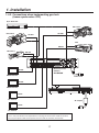
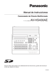
1. Installation
1-4-2. Connections when implementing gen-lock
(frame synchronizer OFF)
Sync Generator
HD camera
HD camera
HD SDI
HD SDI
VTR
HD SDI
HD camera
HD SDI
SLOT A
IN/OUT A1
SLOT B
IN/OUT A2
IN/OUT B1
IN/OUT B2
∼IN1
SDI INPUTS
1
2
3
4
5
6
7
8
9
10
11
12
13
14
15
16
C/C
U/C
SDI OUTPUTS
1
EDITOR
DVI-D OUTPUTS
2
3
4
5
REF
SIGNAL
GND
∼ IN2
6
LAN
PANEL
COM
TALLY/GPI
Multi-format Live
Switcher
HD SDI
AV-HS450N
HD SDI monitor
Power cord
HD SDI
HD SDI monitor
LCD CONTRAST
TALLY / GPI
SERVICE
NORMAL
MAINFRAME
12V IN 1 12V IN 2
POWER
ON
SIGNAL
GND
DVI-D
PC monitor
AC adapter
DVI-D
PC monitor
When the unit is to be installed and when the connections are to be performed, be absolutely
sure to ask your dealer to be responsible for carrying out the work that needs to be done.
Use a 3-point power outlet as the power source in order to earth the unit securely.
17
OFF
1. Installation
1-4-3. Connections when not implementing gen-lock
(frame synchronizer ON)
Example where the optional board is used
SLOT A: Analog Input Board (AV-HS04M2)
SLOT B: Full-HD DVI Input Board (AV-HS04M8)
PC
HD Component
DVI-D
PC
HD camera
HD Component
DVI-D
DVD player
VTR
HD SDI
SD SDI
SLOT A
IN/OUT A1
Y
HD camera
SLOT B
IN/OUT A2
ANALOG INPUTS
Y
Pr
Pb
Pb
IN/OUT B1
IN/OUT B2
DVI INPUTS
Pr
DVI-D
∼IN1
DVI-D
SDI INPUTS
1
2
3
4
5
6
7
8
9
10
11
12
13
14
15
16
C/C
U/C
SDI OUTPUTS
1
EDITOR
DVI-D OUTPUTS
2
3
4
5
REF
SIGNAL
GND
∼ IN2
6
LAN
PANEL
COM
TALLY/GPI
Multi-format Live
Switcher
HD SDI
AV-HS450N
HD SDI monitor
Power cord
HD SDI
LCD CONTRAST
HD SDI monitor
TALLY / GPI
SERVICE
NORMAL
MAINFRAME
12V IN 1 12V IN 2
POWER
ON
SIGNAL
GND
DVI-D
AC adapter
PC monitor
DVI-D
PC monitor
18
OFF
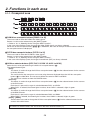
2. Functions in each area
2-1. Control panel
User button area
LCD menu area
Wipe pattern/memory area
SD memory card area
Positioner area
Multi-format Live Switcher AV-HS450
SHOT
MEM
STOR
BKGD
WIPE
MEM
RE
CALL
1
2
3
PAGE
WIPE
1
4
5
4
ALARM
HOLD
F1
F2
F3
F4
F5
1
KEY
PinP1
DSK1
TIME
CKEY
PinP2
DSK2
CBGD
KEY
PinP 1/2
DSK 1/2
AUX1
AMBER:1 / GREEN :2
BKGD
AUX2
IMAGE A
FMEM
CTL
XPT
IN
CONFIG
IMAGE B
SDCard
CAM
MV
OUT
SYS
AUX3
AUX4
2
4
PinP
MEM
DEL
CAM
MEM
UNDO
5
5
7
3
8
6
6
9
7
8
9
10
11
12
10
6
USER
MENU FUNCTION / AUX BUS DELEGATION
3
SQ1
POWER
2
Z
SQ2
SL1
SL2
3D1
3D2
BKGD
PATT
KEY
PATT
XPT DSBL EFF DSLV
POSITIONER
N/R
R
WIPE DIRECTION
MEMORY / PATTERN
AUX
MIX
SHIFT
WIPE
BKGD
KEY
MIX
WIPE
KEY
ON
FTB
ON
PinP1
ON
PinP2
ON
DSK1
ON
DSK2
ON
ON
PGM/A
SHIFT
1/17
2/18
3/19
4/20
5/21
6/22
7/23
8/24
9/25
10/26
11/27
12/28
13/29
PST/B
14/30
15/31
16/32
SHIFT
Crosspoint area
CUT
AUTO
Transition area
Power indicator [POWER]
This indicator lights when the power switch () on the rear panel is set to ON while power is supplied to the
DC power input socket.
It goes off when the power switch () is set to OFF.
Alarm indicator [ALARM]
This indicator lights when the mainframe’s cooling fan has stopped running or when there is a problem (voltage
drop) with the power supply of the mainframe or the control panel.
When this occurs, an alarm message is displayed on the LCD and on the OSD screen of the external monitor.
During the occurrence of an alarm, details of the trouble can be checked using the SYSTEM/Alarm menu.
Alarm information can be output to an external device from the control panel’s TALLY/GPI connector ().
For details, refer to “5-8-2. Alarm message”.
If the alarm goes off, stop using the unit immediately and be sure to contact your dealer.
Continuing to use the unit even after the alarm goes off could damage it.
19
2. Functions in each area
2-1-1. Crosspoint area
KEY
PinP1
DSK1
TIME
CKEY
PinP2
DSK2
CBGD
KEY
PinP 1/2
DSK 1/2
AUX1
AMBER:1 / GREEN :2
BKGD
AUX2
IMAGE A
FMEM
CTL
XPT
IN
CONFIG
IMAGE B
SDCard
CAM
MV
OUT
SYS
AUX3
AUX4
1
2
3
4
5
6
CAM
MEM
USER
MENU FUNCTION / AUX BUS DELEGATION
AUX
SHIFT
PGM/A
SHIFT
1/17
2/18
3/19
4/20
5/21
6/22
7/23
8/24
9/25
10/26
11/27
12/28
13/29
14/30
15/31
16/32
SHIFT
PST/B
PGM/A bus crosspoint buttons [PGM/A 1 to 32]
These are used to select the PGM/A bus video signals.
Buttons 1 to 32 can be selected using the [SHIFT] button.
Refer to “3-1-2. Selecting the bus using the SHIFT function”.
In the case of the flip-flop system, the main line video (PGM) signals are always selected.
When one of the crosspoint buttons (, , ) is held down, the name of the input material and the number of
the crosspoint button are displayed.
PST/B bus crosspoint buttons [PST/B 1 to 32]
These are used to select the PST/B bus video signals.
Buttons 1 to 32 can be selected using the [SHIFT] button.
Refer to “3-1-2. Selecting the bus using the SHIFT function”.
In the case of the flip-flop system, the images inserted next (PST) are always selected.
AUX bus selector buttons [KEY, PinP 1/2, DSK 1/2, AUX1 to AUX4]
Select the bus to be operated using the AUX bus crosspoint buttons ().
The selected button lights.
[KEY]:
This button is used to change the AUX bus crosspoint buttons () into the selector buttons for the sources
of the key fill buses.
The source for the key source bus can be set using the menu displayed when the AUX bus crosspoint
buttons () are held down. The set source will be the same for DSK1 and DSK2.
The source can also be set from the CONFIG menu.
[PinP 1/2]:
This button is used to change the AUX bus crosspoint buttons () into the selector buttons for the sources
of the PinP buses.
Each time it is pressed, its target is switched between PinP1 and PinP2.
When PinP1 is selected, the button lights in amber; when PinP2 is selected, it lights in green.
[DSK 1/2]:
This button is used to change the AUX bus crosspoint buttons () into the selector buttons for the sources
of the DSK fill buses.
Each time it is pressed, its target is switched between DSK1 and DSK2.
When DSK1 is selected, the button lights in amber; when DSK2 is selected, it lights in green.
[AUX1] - [AUX4]:
These buttons are used to change the AUX bus crosspoint buttons () into the selector buttons for the
sources of the AUX buses.
The AUX bus selector buttons are also used as the menu function buttons ().
20
2. Functions in each area
AUX bus crosspoint buttons
These buttons are used to select the source of the bus which was selected by the AUX bus selector button ().
Buttons 1 to 32 can be selected using the [SHIFT] button.
Refer to “3-1-2. Selecting the bus using the SHIFT function”.
2-1-2. Wipe pattern/memory area
Wipe pattern and memory selector buttons
SHOT
MEM
Wipe patterns 1 to 12 can be selected while the BKGD and KEY
pattern selector buttons () are lighted.
Data can be stored in the memories of buttons 1 to 10 or
recalled from these memories while one of the memory
operation buttons () — [SHOT MEM], [BKGD WIPE MEM],
[PinP MEM] or [CAM MEM] — is lighted.
STOR
1
2
3
PAGE
WIPE
1
BKGD
WIPE
MEM
PinP
MEM
CAM
MEM
2
3
SQ1
RE
CALL
DEL
UNDO
4
5
6
4
5
7
8
9
10
11
12
7
8
10
6
SQ2
SL1
SL2
3D1
3D2
9
BKGD
PATT
KEY
PATT
XPT DSBL EFF DSLV
MEMORY / PATTERN
BKGD, KEY pattern selector buttons [BKGD PATT] [KEY PATT]
Press the [BKGD PATT] button, and while it is lighted, select the wipe pattern for the background transition.
Similarly, press the [KEY PATT] button, and while it is lighted, select the wipe pattern for the key transition.
Each time the [BKGD PATT] button and [KEY PATT] button are pressed, the pattern page changes in the
following sequence: WIPE, SQ1 (squeeze 1), SL1 (slide 1), 3D1 (3 dimensions 1), SQ2 (squeeze 2), SL2
(slide 2) and 3D2 (3 dimensions 2). Which pattern page has been selected can be checked by observing which
pattern page indicator LED () is lighted.
SQ2, SL2, and 3D2 may not be selected as the wipe pattern for the key transition.
Pattern page indicator LEDs [PAGE]
By observing which pattern page indicator LED is lighted, it is possible to check which pattern page has been
selected by the BKDG PATT or KEY PATT selector button ().
Memory operation buttons [SHOT MEM] [BKGD WIPE MEM] [PinP MEM] [CAM MEM]
[STOR] [RECALL] [DEL] [UNDO]
Press the [SHOT MEM], [BKGD WIPE MEM], [PinP MEM] or [CAM MEM] button to perform the memory
operations for the number keys (1 to 10).
[STOR]:
Press this to register data in the memory.
[RECALL]:
Press this to recall data from the memory.
[DEL]:
Press this to delete data in the memory.
[UNDO]:
Press this to undo the operation of the [RECALL] or [DEL] button.
The number of operations that can be undone is one only.
This operation cannot be performed using memory operations when the [CAM MEM] button has been
pressed.
21
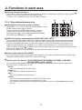
2. Functions in each area
2-1-3. User button area
User buttons [USER1 to USER6]
These are used to assign some functions of the menu settings to the [USER1]
to [USER6] buttons on the CONFIG menu.
See “5-3-1. Setting the user buttons”.
1
4
2
3
5
6
USER
2-1-4. Transition area
UNDO
8
9
10
12
10
XPT DSBL EFF DSLV
11
KEY
PATT
N/R
R
WIPE DIRECTION
MEMORY / PATTERN
MIX
WIPE
BKGD
MIX
KEY
ON
FTB
ON
PinP1
ON
PinP2
ON
DSK1
ON
DSK2
ON
KEY
ON
WIPE
CUT
AUTO
[BKGD] button
This executes the background transition when the [AUTO] button () or fader lever () has been operated.
When the [BKGD] button is pressed and it is selected, its indicator lights in amber.
If the [KEY] button () is now pressed, the indicator goes off, and the de-selected status is established.
When the [BKGD] button and [KEY] button () are pressed at the same time, both buttons are set to the
selected status.
[KEY] button
This executes the key transition when the [AUTO] button () or fader lever () has been operated.
When the [KEY] button is pressed and it is selected, its indicator lights in amber.
If the [BKGD] button () is now pressed, the indicator goes off, and the de-selected status is established.
When the [BKGD] button () and [KEY] button are pressed at the same time, both buttons are set to the
selected status.
KEY ON tally LED
This lights in red when the key ON status is established.
MIX, WIPE selection status tally LEDs
These light up to indicate whether MIX or WIPE has been selected when background transitions or key
transitions are executed.
22
2. Functions in each area
[MIX] button
This is used to switch the A and B bus images while making them overlap.
During the transition, the A and B bus output total is kept at 100 %.
When the [MIX] button is pressed and it is selected, its indicator lights in amber.
If the [WIPE] button () is now pressed, it goes off, and the de-selected status is established.
[WIPE] button
This is used to execute the transition using the pattern selected by the wipe pattern selector button ().
When the [WIPE] button is pressed and it is selected, its indicator lights in amber.
If the [MIX] button () is now pressed, it goes off, and the de-selected status is established.
[AUTO] button
This is used to automatically execute transitions (auto transition) using the transition time which has been set
on the TIME menu.
During auto transition its indicator lights in amber. When the button is pressed again during auto transition, the
auto transition operation is suspended, and the indicator lights in green. When it is pressed again while auto
transition is suspended, the remaining transition is executed.
The indicator goes off when auto transition is completed.
When the [AUTO] button is pressed while the fader lever () is at an interim setting, the transition is executed
in the time remaining from the interim setting.
[CUT] button
This button is used to execute transitions instantly.
Its indicator lights in amber during a transition, and it goes off when the transition is completed.
[KEY ON] button
This button is used to execute the key transition for the transition time which has been set on the TIME menu.
[FTB ON] button
This button is used to execute fade-out to a black screen or fade-in from a black screen for the transition time
which has been set on the TIME menu.
PinP button [PinP1 ON] [PinP2 ON]
This button is used to execute fade-in or fade-out of the picture in picture for the transition time which has been
set on the TIME menu.
DSK button [DSK1 ON] [DSK2 ON]
This button is used to execute fade-in or fade-out of downstream key for the transition time which has been set
on the TIME menu.
23
2. Functions in each area
Wipe direction selection buttons [WIPE DIRECTION N/R, R]
These buttons are used to select the direction in which to wipe for executing background transitions.
When the [R] indicator is off:
Wiping proceeds in the normal direction.
When the [R] indicator is lighted:
Wiping proceeds in the reverse direction.
When the [N/R] indicator is lighted:
The normal direction is replaced with the reverse direction (or vice versa) when the transition is
completed. (The lighted and extinguished statuses of the [R] button are also switched in line with the
direction of the wiping.)
Fader lever
This is used to execute background or key transitions. When it is moved as far as it will go, the transition
is completed. When it has been operated during auto transition, auto transition will be switched to manual
operation as soon as the fader position overtakes the amount of the transition being executed.
Bus tally LEDs
These indicate the output statuses of the A bus and B bus. The LED corresponding to the bus whose program
signals (PGM) are being output lights.
24
2. Functions in each area
2-1-5. LCD menu area
POWER
ALARM
HOLD
F1
KEY
PinP1
F2
DSK1
TIME
CKEY
PinP2
DSK2
CBGD
KEY
PinP 1/2
DSK 1/2
AUX1
AMBER:1 / GREEN :2
F3
BKGD
AUX2
F4
F5
IMAGE A
FMEM
CTL
XPT
IN
CONFIG
IMAGE B
SDCard
CAM
MV
OUT
SYS
AUX3
AUX4
MENU FUNCTION / AUX BUS DELEGATION
LCD
The setting menu is displayed when one of the menu function buttons () is pressed.
When the buttons listed below are double-clicked, the specified menu is selected. (The menu delegation
function)
The operation corresponding to the button pressed is also executed.
<List of menu delegation functions>
Button
Transition area
BKGD
KEY
WIPE
Wipe pattern area
Menu
TIME menu/BKGD sub menu
TIME menu/KEY sub menu
BKGD menu/Border sub menu
WIPE #5
(BKGD)
BKGD menu/WIPEPos sub menu
WIPE #5
(KEY)
KEY menu/WIPEPos sub menu
WIPE #11
(BKGD)
BKGD menu/WIPEPos sub menu
WIPE #11
(KEY)
KEY menu/WIPEPos sub menu
SQ #5
(BKGD)
BKGD menu/SQPos sub menu
SQ #5
(KEY)
KEY menu/SQPos sub menu
SL #5
(KEY)
KEY menu/FlyKEY sub menu
25
2. Functions in each area
Menu function buttons [MENU FUNCTION/AUX BUS DELEGATION]
These are used to select the menus organized by function.
Each time one of these buttons is pressed, the menu for its function is switched between the one displayed
above and the one displayed below. Each time the [PinP1/PinP2] button or [DSK1/DSK2] button is pressed, the
color used for their lighting is switched between amber and green. The other buttons light in amber.
Rotary encoders [F1] to [F5]
These are used to set the parameters displayed on the menus (LCD screen or on-screen display).
For details on the operations, refer to the sections in “3. Basic operations”.
[F1]:
Rotate this rotary encoder to switch the sub menu.
On the INPUT menu or OUTPUT menu, the signal to be set is switched.
[F2]:
Turn this rotary encoder to set the parameters.
On the INPUT menu or OUTPUT menu, the third menu is switched.
[F3] to [F5]: Rotate these rotary encoders to set the parameters.
When the down arrow (↓) is shown at a menu item, its parameter is set by pressing the corresponding rotary
encoder.
When the parameter is one which is set using a numerical value, its default will be restored when the rotary
encoder is held down.
(However, the network settings and the date and time settings will not be returned to the defaults.)
Basic menu operations
For detailed operations, refer to the sections in “3. Basic operations”.
For the menu configurations, refer to “8. Setting menu table”.
Select the menus organized by function using the menu function buttons ().
Using the rotary encoders (), display the sub menu that will be used to establish the detailed settings,
and set the parameters.
Parameter setting area
Third menu
Sub menu
|Gain
|Density|Invert
KEY
2|Clip
Adjust |
0.0| 100.0| 100.0|
Off
Operate here
using [F1].
Operate here
using [F2].
Operate here
using [F3].
Operate here
using [F4].
Operate here
using [F5].
The INPUT menu and OUTPUT menu differ depending on whether an option board has been installed.
[HOLD] button
If the [HOLD] button is pressed while a menu is displayed, no other menu will be selected even when a menu
function button () is pressed.
In addition, even if the AUX bus selection button () is pressed it will not switch to another bus.
While the [HOLD] button is held down, it lights in amber.
26
2. Functions in each area
2-1-6. Positioner area
Positioner [X/Y]
These are used when performing the settings below.
PinP1, PinP2 position settings
Wipe start position setting (WIPE #5, WIPE #11, SQ #5)
Camera control
Flying key position setting
Chroma key marker position setting
Z
POSITIONER
In each case, the settings take effect only when the following menu items have been selected.
Note
The center values of the positioner are set during the time it takes for the unit to start up after its power is
turned on. Do not operate the positioner until after the switcher has started up.
Rotary encoder [Z]
This is used to set the PinP size, flying key size or to select the chroma key area.
In each case, the settings take effect only when the following menu items have been selected.
Positioner
Rotary encoder
X/Y
PinP1, PinP2
Z
Switch
Valid menu
Position adjustments
Size adjustments
Hold switch down to
(size increased by rotating restore initial values
the encoder clockwise
(X/Y, Z).
and reduced by rotating it
counterclockwise)
All PinP1 and PinP2
menus (except for
PinP1, PinP2/Rotation)
Rotation angle
adjustments
(X-direction and
Y-direction rotation)
Rotation angle
adjustments
(Z-direction rotation)
Hold switch down to
restore initial values
(X/Y, Z).
PinP1, PinP2/
Rotation
WIPE (BKGD)
Start position
adjustments
—
Hold switch down to
restore initial values
(X/Y).
BKGD/WIPEPos
BKGD/SQPos
WIPE (KEY)
Start position
adjustments
—
Hold switch down to
restore initial values
(X/Y).
KEY/WIPEPos
KEY/SQPos
Chroma key
Selection position
adjustments
Selected area size
Execute sampling
adjustments
(size increased by rotating
the encoder clockwise
and reduced by rotating it
counterclockwise)
CHR KEY/Sample1
CHR KEY/Sample2
Position adjustments
Size adjustments
Hold switch down to
(size increased by rotating restore initial values
the encoder clockwise
(X/Y, Z).
and reduced by rotating it
counterclockwise)
KEY/FlyKEY
Flying key
Camera control
X: Pan control or focus
control
Y: Tilt control or zoom
control
—
27
Switching between
pan/tilt control and
zoom/focus control
All menus other than
those listed above
2. Functions in each area
2-1-7. SD memory card area
SD memory card slot
Insert an SD memory card (purchased separately) or an SDHC memory card
(purchased separately) into this slot.
SD memory card access LED
This LED lights while the data on the SD memory card is being accessed.
Do not turn off the unit’s power or eject the SD memory card while the access LED is lighted.
Doing so can damage the data on the SD memory card.
Concerning the recommended SD memory cards and SDHC memory cards
Use of the following SD memory cards and SDHC memory cards made by Panasonic is recommended:
SDHC memory cards RP-SDM04G, RP-SDM06G, RP-SDM08G,
RP-SDM12G, RP-SDM12G
RP-SDV04G, RP-SDV08G, RP-SDV16G,
RP-SDV32G
SD memory cards
RP-SD128B, RP-SD256B
RP-SDR512
RP-SDM01G, RP-SDM02G
RP-SDV512, RP-SDV01G, RP-SDV02G
28
2. Functions in each area
2-1-8. Rear panel connections area
LCD CONTRAST
TALLY / GPI
NORMAL
SERVICE
12V IN 1 12V IN 2
MAINFRAME
POWER
ON
OFF
SIGNAL
GND
TALLY/GPI input/output connector [TALLY/GPI] (D-sub 25-pin, female, inch screw)
For details on how to connect this connector, refer to “6. External interfaces”.
MAIN FRAME connector [MAIN FRAME] (RJ-45) (100 Base-TX)
Connect this to the mainframe using the supplied CAT5E cable (STP, straight, 10 m).
DC power input sockets [12V
IN1], [12V
IN2] (DC 12 V, 0.8 A)
Connect the supplied AC adapters (for the control panel) to these sockets.
Ground connector [SIGNAL GND]
Connect to the system’s earth ground.
Power switch [POWER]
This is used to turn the power on and off.
SERVICE switch [NORMAL/SERVICE]
This switch is used for maintenance purposes.
For normal operations, select the “NORMAL” position.
LCD CONTRAST adjustment screw
This is used to adjust the contrast of the LCD display.
29
2. Functions in each area
2-2. Mainframe
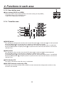
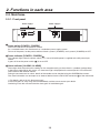
2-2-1. Front panel
Power supply 1
POWER1
OFF
ON
POWER1
ALARM1
Power supply 2
POWER2
OFF
ON
POWER2
ALARM2
Multi-format Live Switcher AV-HS450
Power switch [POWER1, POWER2]
These are used to turn the power on and off.
As a standard feature, this mainframe has a redundant power supply system.
To turn off the power, set the power switches of both system 1 (POWER1) and system 2 (POWER2) to OFF.
Power indicator [POWER1, POWER2]
This indicator lights when the power switch () is set to ON while power is supplied to the AC power input
socket.
It goes off when the power switch () is set to OFF.
Alarm indicator [ALARM1, ALARM2]
These light when the mainframe’s cooling fan has stopped running or when there is a problem (voltage drop)
in the power supply. When this occurs, an alarm message is displayed on the control panel’s LCD and on the
OSD screen of the external monitor.
During the occurrence of an alarm, details of the trouble can be checked using the SYSTEM/Alarm menu.
The alarm information can be output to an external device from the TALLY/GPI connector () of the mainframe.
For details, refer to “5-8-2. Alarm message”.
If the alarm goes off, stop using the unit immediately and be sure to contact your dealer.
Continuing to use the unit even after the alarm goes off could damage it.
30
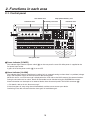
2. Functions in each area
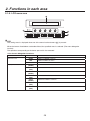
2-2-2. Rear panel connections area
SLOT A
IN/OUT A1
SLOT B
IN/OUT A2
IN/OUT B1
IN/OUT B2
∼IN1
SDI INPUTS
1
2
3
4
5
6
7
8
9
10
11
12
13
14
15
16
C/C
SIGNAL
GND
U/C
SDI OUTPUTS
1
EDITOR
DVI-D OUTPUTS
2
3
4
5
LAN
REF
∼ IN2
6
PANEL
TALLY/GPI
COM
SDI signal input connectors [SDI INPUTS 1 to 16]
9 to 16: The color collector function can be used.
13 to 16: The up-converter function can be used.
Option slot [SLOTA] (IN/OUT A1, IN/OUT A2)
Option slot [SLOTB] (IN/OUT B1, IN/OUT B2)
Each of these is an input/output option slot.
A DVI input board, analog output board or other option board can be installed in these slots.
For details, refer to “1-3. How to install the option boards” and the operating instructions of the board
concerned.
SDI signal output connectors [SDI OUTPUTS 1 to 4]
1 to 4: These can be allocated by the menus.
Two sets of the same output signals are distributed from the OUTPUT1 connector.
DVI-D output connectors [DVI-D OUTPUTS 5, 6]
These can be allocated by the menus.
The DVI-I connector cable cannot be used.
Reference input connector/BB output
connector [REF]
<In the external synchronization mode>
Loop-through output in the external sync mode.
If the loop-through output is not going to be used,
provide a 75-ohm termination.
BB signals output from both connectors in the internal
sync mode.
External synchronization signal input
REF
Loop-through output
Input the external synchronization signal to the upper of
the two connectors shown above.
PANEL connector [PANEL] (RJ-45) (100 Base-TX)
Connect this to the control panel using the supplied CAT5E cable (STP, straight, 10 m).
31
2. Functions in each area
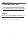
LAN connector [LAN] (RJ-45) (10/100 Base-TX)
For details on how to connect this connector, refer to “6. External interfaces”.
EDITOR connector [EDITOR] (RS-422, D-sub 9-pin, female, inch screw
COM connector [COM] (RS-422, D-sub 9-pin, female, inch screw)
For details on how to connect this connector, refer to “6. External interfaces”.
TALLY/GPI input/output connector [TALLY/GPI] (D-sub 50-pin, female, inch screw)
For details on how to connect this connector, refer to “6. External interfaces”.
Ground connector [SIGNAL GND]
Connect to the system’s earth ground.
AC power input socket [
IN1] [
IN2] (AC 100 V to 120 V, 50/60 Hz)
Connect one end of the supplied power cable to this socket and the other end to the AC outlet.
The supplied power cable comes with a 3-pin power plug. Be absolutely sure to plug it into a 3-point power
outlet as the power source in order to earth the unit securely.
If a 3-point power outlet is not available for this connection, be absolutely sure to consult your dealer.
Cooling fan
32
3. Basic operations
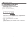
3-1. Background transition
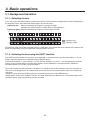
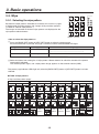
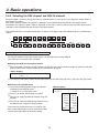
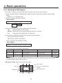
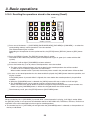
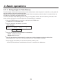
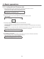
3-1-1. Selecting the bus
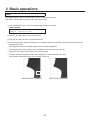
Press one of the crosspoint buttons to select the material to be used for the background transition. Depending on
the operating status, the button pressed will light in one of two colors.
Lighting in red:
When the selected input signals are output to PGM.
(However, the indicator lights in amber during FTB operations.)
Lighting in green: When the selected input signals are not output to PGM.
AUX
SHIFT
PGM/A
SHIFT
1/17
2/18
3/19
4/20
5/21
6/22
7/23
8/24
9/25
10/26
11/27
12/28
13/29
14/30
PST/B
15/31
16/32
SHIFT
Lighting in red
Lighting in green
Furthermore, when one of the crosspoint buttons is held down, the name of the input material and number of the
button corresponding to the pressed button are displayed on the LCD.
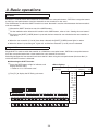
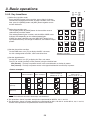
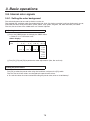
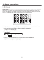
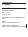
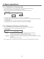
3-1-2. Selecting the bus using the SHIFT function
The SHIFT function enables two materials to be allocated — the front material and the rear material — to one
button, and the materials to be selected using the [SHIFT] button.
A total of 32 materials — front materials (1 to 16) and rear materials (17 to 32) — can be allocated to the three
groups of 16 crosspoint buttons whether these buttons are the PGM/A bus crosspoint buttons, PST/B bus
crosspoint buttons or AUX bus crosspoint buttons.
There are actually two SHIFT functions: “All SHIFT” for switching all the front materials to the rear materials or
vice versa, and “Single SHIFT” for switching the front material of one crosspoint button with its rear material or
vice versa.
“All SHIFT” works once the SHIFT function has been allocated to one of the USER buttons.
“Single SHIFT” works once the SHIFT function has been allocated to the No.16 or No.1 crosspoint button of the
crosspoint button group concerned by a menu operation.
33
3. Basic operations
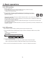
All SHIFT
All SHIFT is used to switch all the materials of the PGM/A bus crosspoint buttons, PST/B bus crosspoint buttons
or AUX bus crosspoint buttons from front materials to rear materials or vice versa.
The USER button to which the SHIFT function has been allocated is used to switch between the front materials
and rear materials.
Allocate the SHIFT function to one of the USER buttons.
For the method used to allocate this function to the USER button, refer to “5-3-1. Setting the user buttons”.
Each time the [SHIFT] (USER) button is pressed, the front materials are switched to the rear materials or
vice versa.
When the rear materials (17 to 32) have been selected, the [SHIFT] (USER) button lights in amber.
When the button is pressed again, it goes off, and the front materials (1 to 16) are now selected.
Single SHIFT
Single SHIFT is used to switch the material of a PGM/A bus crosspoint button, PST/B bus crosspoint button or
AUX bus crosspoint button from a front material to a rear material or vice versa.
Switching between the front material and rear material is done using the crosspoint button (No.16 or No.1) in
which the SHIFT function is allocated.
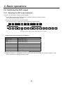
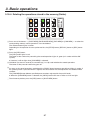
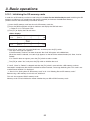
Allocating the SHIFT function
Press the [XPT] button to light its indicator, and
display the XPT menu.
Refer to “2-1-5. LCD menu area”.
<Menu display>
XPT
5|XPT
XPTAsing|
1~32
Turn [F1] to display the XPTAsing sub menu.
KEY
PinP1
DSK1
TIME
CKEY
PinP2
DSK2
CBGD
KEY
PinP 1/2
DSK 1/2
AUX1
AMBER:1 / GREEN :2
BKGD
AUX2
|Signal |Shift |Sf-Lock
—|
—| Right|
Off
IMAGE A
FMEM
CTL
XPT
IN
CONFIG
IMAGE B
SDCard
CAM
MV
OUT
SYS
AUX3
AUX4
1
2
3
4
5
6
CAM
MEM
USER
MENU FUNCTION / AUX BUS DELEGATION
AUX
SHIFT
PGM/A
SHIFT
1/17
2/18
3/19
4/20
5/21
6/22
7/23
8/24
9/25
10/26
11/27
12/28
13/29
14/30
15/31
16/32
SHIFT
PST/B
34
IN1~16
IN-A1
IN-A2
IN-B1
IN-B2
Black
CBGD
CBAR
FMEM1~4
PGM
PVW
CLN
MV1
MV2
None
Left
Off
On
3. Basic operations
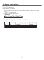
Turn [F4] to select the button to which the SHIFT function is to be allocated using the Shift item.
Right: Button No.16
Left: Button No.1
Off: Function is not allocated.
Turn [F5] to select the operation to be performed when the [SHIFT] button is pressed using the Sf-Lock item.
Off: The rear material is selected only while the [SHIFT] button is pressed.
On: The front material and rear material are switched each time the [SHIFT] button is pressed.
To use the materials that have been set in the button to which the SHIFT function is allocated, either set the
SHIFT function off or allocate the SHIFT function to another button.
If a rear material has been selected regardless of whether the Sf-Lock item is On or Off, both the button
concerned and the [SHIFT] button will light in amber.
When PGM/PST is selected as the bus mode setting or when the bus has been switched by a transition, the
SHIFT status will also be switched.
If the [SHIFT] button for “Single SHIFT” is pressed when the rear materials (17 to 32) have been selected
using “All SHIFT”, the bus crosspoint buttons concerned will be switched to the front materials.
When a crosspoint button is held down, the input material allocated to the pressed button is displayed on the
LCD.
When the [SHIFT] button is held down, “Shift” is displayed on the LCD.
35
3. Basic operations
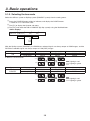
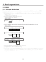
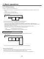
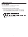
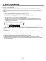
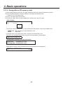
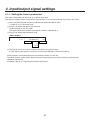
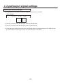
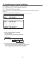
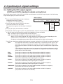
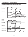
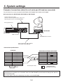
3-1-3. Selecting the bus mode
Select the A/B bus system or flip-flop system (PGM/PST system) from the setting menu.
Press the [CONFIG] button to light its indicator, and display the CONFIG menu.
Refer to “2-1-5. LCD menu area”.
Turn [F1] to display the Operate sub menu.
Turn [F2], and select the A/B or PGM/PST (flip-flop system) using the BusMode item.
<Menu display>
CONFIG 1|BusMode|LCD-BL |MENUDLG|
Operate |PGM/PST|
On|
On|
A/B
Off
60
120
180
Off
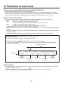
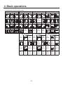
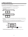
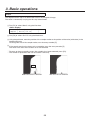
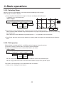
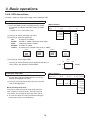
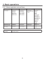
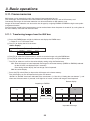
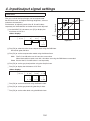
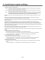
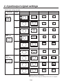
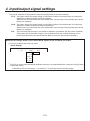
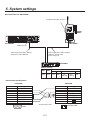
With the flip-flop system (PGM/PST), the PGM/A bus selected signals are always output as PGM images, and the
PST/B bus selected signals are always output as PVW (PST) images.
System
A/B
Video output
PGM
PVW (PST)
With an A B transition
Before transition
PGM/A
PST/B
During transition
PGM/A, PST/B
PST/B
PGM/A
1/17
2/18
1/17
2/18
1/17
2/18
PST/B
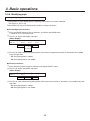
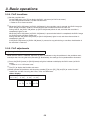
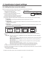
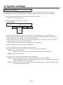
System
Flip-flop
PGM/PST
Video output
PGM
PVW (PST)
After transition completion
PST/B
PGM/A
Lighting in red
Lighting in green
Before transition
PGM/A
PST/B
During transition
PGM/A, PST/B
PST/B
After transition completion
PGM/A
PST/B
PGM/A
1/17
2/18
1/17
PST/B
2/18
1/17
2/18
Lighting in red
Lighting in green
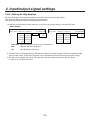
36
3. Basic operations
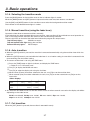
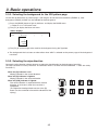
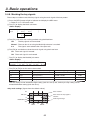
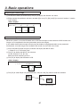
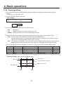
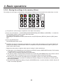
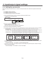
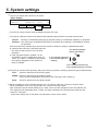
3-1-4. Selecting the transition mode
Press the [BKGD] button in the transition area so that its indicator lights in amber.
When the [BKGD] button and [KEY] button are pressed at the same time, both buttons are selected.
Use the [MIX] and [WIPE] buttons in the transition area to select the background transition mode.
The indicator of the selected button lights in amber.
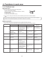
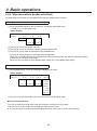
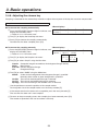
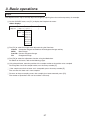
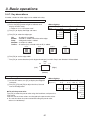
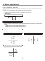
3-1-5. Manual transition (using the fader lever)
Operate the fader lever to execute transitions manually.
If the fader lever has been operated during auto transition, auto transition will be switched to manual operation as
soon as the fader position overtakes the amount of the transition being executed.
The bus tally LEDs on the left of the fader lever indicate the program bus output status.
Top LED only lights:
PGM/A bus output
Top and bottom LEDs light: during the transition
Bottom LED only lights:
PST/B output
3-1-6. Auto transition
When the [AUTO] button is pressed, the transition is executed automatically using the transition time which has
been set.
When the [AUTO] button is pressed while the fader lever is at an interim setting, the transition is executed in the
time remaining from the interim setting.
The auto transition time is set using the TIME menu.
Press the [TIME] button to light its indicator, and display the TIME menu.
Refer to “2-1-5. LCD menu area”.
Turn [F1] to display the BKGD sub menu.
Turn [F4] to select the display unit using the Unit item.
When frames (Frame) have been selected as the unit, turn [F3] to set the transition time.
When seconds (Sec) have been selected as the unit, turn [F2] to set the second units or [F3] to set the
frame units.
<Menu display>
TIME
BKGD
1|TransTime
|
16s|
|Unit
|
39f|
Sec|
TIME
BKGD
1|TransTime
|
|Unit
|
999f| Frame|
Any time from 0 to 999f can be set. The time which can be set when seconds are used as the display unit differs
depending on the video format.
59.94i: max. 33s09f, 59.94p: max. 16s39f, 50i: max. 39s24f, 50p: max. 19s49f,
24psf: max 41s15f, 23.98psf: max 41s15f
3-1-7. Cut transition
When the [CUT] button is pressed, the transition is executed instantly.
37
3. Basic operations
3-2. IMAGE
3-2-1. Setting the IMAGE effects
Three effects — paint, mono-color, mosaic and defocus — can be set for the PGM/A bus materials and PST/B
bus materials.
Press the [IMAGE A] button (or the [IMAGE B] button) to light its indicator, and display the IMAGE A (or
IMAGE B) menu.
Refer to “2-1-5. LCD menu area”.
Turn [F2], and set the IMAGE effect to On or Off.
To add the IMAGE effect, set to On.
<Menu display>
IMAG A 1|On/Off |
IMAG A |
Off|
|
|
|
|
On
Turn [F1] to display the menu (Paint, Mono, Mosa/Def sub menu) of the effect that is to be set.
<Menu display>
IMAG A 2|On/Off |Y-Level|C-Level|
Paint
|
Off|
0|
0|
On
0~7
0~7
|Sat
|
IMAG A 3|On/Off |Hue
Mono
|
Off|
0.0|
0.0|
On
0.0
|
359.9
0.0
|
100.0
|Effect |
IMAG A 4|On/Off |Mode
Mosa/Def|
Off|Mosaic |
20.0|
On Defocus
0.0
|
100.0
Turn [F2], and set On or Off using the sub menu concerned.
Turn [F3] and [F4], and change the effect setting.
Executing the transition when the PGM/PST (flip-flop system) is selected in the BusMode item of the Operate
submenu of the CONFIG menu replaces the PGM/A bus with the PST/B bus, and the menu title “IMAG A” is
also replaced with “IMAG B”.
38
3. Basic operations
3-2-2. Executing the IMAGE effect
While the IMAGE effect is set to On, the crosspoint button with the bus material to which the IMAGE effect has
been added now blinks.
The IMAGE effects are created as DVEs (digital video effects) so their output is delayed by one frame from the
normal output.
Even when the IMAGE effect has been set to On only for the PGM/A bus or PST/B bus, the effects of both buses
will be output with a 1-frame delay.
39
3. Basic operations
3-3. Wipe
1
2
PAGE
3
WIPE
3-3-1. Selecting the wipe pattern
1
2
3
SQ1
4
Based on the wipe patterns allocated to 12 buttons, this unit has 7 pages
of background transition patterns and 4 pages of key transition patterns.
(Refer to “Table of wipe patterns”.)
The images and number of the basic wipe patterns are displayed on the
wipe pattern selector buttons.
5
4
6
5
7
6
8
7
8
9
11
12
10
SL2
3D1
3D2
BKGD
PATT
9
10
KEY
PATT
XPT DSBL EFF DSLV
MEMORY / PATTERN
<How to select the wipe patterns>
Press the [BKGD PATT] button or [KEY PATT] button to select the pattern page.
Each time the button is pressed, the page is switched, and the selected PAGE LED lights.
Type of transition
Pattern page selection
PAGE LED lighting
Background
[BKGD PATT] button
WIPE SQ1 SL1 3D1 SQ2 SL2 3D2
Key
[KEY PATT] button
WIPE SQ1 SL1 3D1
Select the button from among the 12 wipe pattern selector buttons for which the number of the pattern
concerned is indicated.
The selected pattern lights, and a wipe pattern image appears on the external monitor (OSD).
The pattern page indicator LEDs light only when the [BKGD PATT] button or [KEY PATT] button has been
selected.
Table of wipe patterns
Key transition pattern pages
WIPE
1
2
SQ1 (squeeze 1)
3
2
1
SQ
4
5
6
4
7
8
9
5
7
11
12
10
SQ
1
SQ
SQ
SQ
9
11
No
pattern
SQ
No
pattern
SQ
40
3
5
SQ
8
3
4
5
6
7
8
9
10
11
12
SL
SL
No
pattern
2
SL
9
11
1
SL
6
SL
10
12
3D1 (3 dimensions 1)
SL
SL
7
SQ
2
SL
4
6
8
SQ
10
3
SQ
SQ
SL1 (slide 1)
12
No
pattern
SQ2
SL1
3. Basic operations
Background transition pattern pages
WIPE
1
2
SQ2 (squeeze 2)
3
1
SQ
4
5
6
8
9
7
8
11
12
SQ
9
10
11
SQ
SQ
No
pattern
SQ
SQ2 (squeeze 2)
1
2
No
pattern
4
SQ SQ
7
No
pattern
10
No
pattern
SQ
5
1
No
pattern
8
SQ
SQ
11
No
pattern
6
8
3
4
5
6
7
8
9
10
11
12
SL
9
SL
SL
11
2
SL
No
pattern
12
No
pattern
No
pattern
SQ SQ
SL SL
9
7
No
pattern
12
10
No
pattern
41
SL
SL
5
No
pattern
No
pattern
6
No
pattern
SL
SL
11
No
pattern
1
No
pattern
12
No
pattern
2
No
pattern
4
3
No
pattern
5
6
No
pattern
SL SL
9
8
No
pattern
3D2 (3 dimensions 2)
3
2
No
pattern
4
6
No
pattern
5
1
SL2 (slide 2)
3
SQ
3D2 (3 dimensions 2)
3
SL
SL
10
12
No
pattern
SL
7
SQ
2
SL
4
SQ
SQ
10
SQ
6
5
SQ
7
1
SQ
4
SL2 (slide 2)
3
2
7
8
No
pattern
10
No
pattern
9
No
pattern
11
No
pattern
12
No
pattern
3. Basic operations
3-3-2. Selecting the background for the 3D2 pattern page
On the 3D2 (3 dimensions 2) pattern page, a still image in one of the frame memories (FMEM1-4), color
background (CBGG) or Black can be selected for the background.
Press the [BKGD] button to light its indicator, and display the BKGD menu.
Refer to “2-1-5. LCD menu area”.
Turn [F1] to display the Base sub menu.
<Menu display>
BKGD
Base
|
6|Type
| Black|
|
|
|
|
FMEM1
|
FMEM4
CBGD
Turn [F2] to set the image to be used for the background using the Type item.
The background that has been set takes effect when “3D2” is selected on the pattern page of the background
transitions.
3-3-3. Selecting the wipe direction
Operate the wipe direction selector buttons to select the wipe direction for the background transition.
(The key transitions are set by the menu. The direction which is set here will not be reflected. See “3-4-3. Key
transitions”.)
When the [R] indicator is off:
Wiping proceeds in the normal direction.
When the [R] indicator is lighted:
Wiping proceeds in the reverse direction.
A
When the [N/R] indicator is lighted:
The normal direction is replaced with the reverse
direction (or vice versa) when the transition is
completed.
(The lighted and extinguished statuses of the [R]
button are also switched in line with the direction of the
wiping.)
R
A
B
B
A
B
A
A
B
N/R
A
B
B
A
B
42
N
A
B
3. Basic operations
3-3-4. Wipe decorations (border, soft effect)
A border effect or soft effect can be added to the wiping of background transitions.
Setting the border and soft effect
Press the [BKGD] button to light its indicator, and display the BKGD menu.
Refer to “2-1-5. LCD menu area”.
<Menu display>
BKGD
1|Border |
Border |
Off|
On
Width|
5.0|
0.1
|
100.0
Soft|
0.0|
0.0
|
100.0
Turn [F1] to display the Border sub menu.
Turn [F2] to set On (or Off) for the border using the Border item.
Turn [F3] to set the width of the border using the Width item.
Turn [F4] to set the amount of soft effect using the Soft item.
When “On” has been selected as the Border item setting, the ratio of the soft effect to the border width is
indicated as the amount of soft effect.
When only the soft effect is to be added to wipe, select “Off” as the Border item setting.
Setting the border color
On the BKGD menu, turn [F1] to display the BodrCol sub menu.
<Menu display>
|Sat
|Lum
|Load↓
BKGD
2|Hue
BodrCol |
0.0|
0.0| 100.0| White
0.0
|
359.9
0.0
|
100.0
0.0
|
108.0
Yellow
Cyan
Green
Magenta
Red
Blue
Black
Turn [F2], [F3] and [F4] to adjust the Hue, Sat and Lum of the border color.
To call the preset color
Turn [F5] to select the preset color using the Load item, and press the [F5] switch.
The Hue, Sat and Lum values are changed to the preset color values.
To save the values that were set before calling the preset color, refer to “3-10. Preset memory”.
43
3. Basic operations
3-3-5. Setting the wipe start position
Any start position can be set for WIPE patterns No.5 and No.11 and for SQ pattern No.5 among the wipe patterns.
For WIPE patterns No.5 and No.11, the position is set using the WIPEPos sub menu of the BKGD menu.
For SQ pattern No.5, it is set using the SQPos sub menu of the BKGD menu.
Press the [BKGD] button to light its indicator, and display the BKGD menu.
Refer to “2-1-5. LCD menu area”.
Turn [F1] to display the WIPEPos sub menu or the SQPos sub menu.
<Menu display>
BKGD
3|X-Pos |Y-Pos |
WIPEPos |
0.00|
0.00|
-100.0
|
100.0
BKGD
SQPos
|
-100.0
|
100.0
4|X-Pos |Y-Pos |
|
0.00|
0.00|
-100.0
|
100.0
|CopyTo↓
|CopyTo↓
|
-100.0
|
100.0
Either operate the positioners or turn [F2] and [F3] to set the wipe start position using the X-Pos item and
Y-Pos item.
These settings can be established only when WIPE or SQ #5 has been selected as the background pattern
or key pattern.
Either operate the fader lever or press the [AUTO] button to check the wipe operation.
(When, for instance, –50 has been set for X-Pos and –50 for Y-Pos, the following screen (or key) appears
from the bottom left and wipe is performed while the screen (or key) moves to the screen center.)
<X-Pos, Y-Pos setting range>
Inside screen area
Outside screen area
To copy the start position settings, press [F5].
The copy destination appears under the CopyTo item. (It will not change even if [F5] is turned.)
44
3. Basic operations
3-3-6. Modifying wipe
Setting the lighting effect
Lighting effects can be added when the following wipe patterns have been selected:
3D1 page: #1, #3, #7, #9
These effects can be set for background transitions and key transitions.
For background transitions
Press the [BKGD] button to light its indicator, and display the BKGD menu.
Refer to “2-1-5. LCD menu area”.
Turn [F1] to display the Modify sub menu.
<Menu display>
|4:3Auto|
BKGD
5|Light |Trim
Modify |
Off|
Off|
Off|
On
16:9
4:3
4:3Smth
On
Turn [F2] to select whether the lighting effect at the time a background transition is executed is to be added
using the Light item.
On: The lighting effect is added.
Off: The lighting effect is not added.
For key transitions
Press the [KEY] button to light its indicator, and display the KEY menu.
Turn [F1] to display the Modify sub menu.
<Menu display>
KEY
9|Light |
Modify |
Off|
|
|
|
|
On
Turn [F2] to select whether the lighting effect at the time a key transition is executed is to be added using the
Light item.
On: The lighting effect is added.
Off: The lighting effect is not added.
45
3. Basic operations
Setting the trimming
When SQ1, SQ2, SL1, SL2, 3D1 or 3D2 has been selected as the wipe pattern, the trimming at the time a
background transition is executed can be set.
The “4:3” and “4:3Smth” settings for the Trim item take effect when the HD format has been selected as the
system format setting.
On the BKGD menu, turn [F1] to display the Modify sub menu.
<Menu display>
|4:3Auto|
BKGD
5|Light |Trim
Modify |
Off|
Off|
Off|
On
16:9
4:3
4:3Smth
On
Turn [F3] to set the trimming operation and transition operation using the Trim item.
16:9 (On): For trimming the edges around the material.
This setting is used when a black border, for instance, can be seen around the material.
When HD has been selected as the system format setting, “16:9” is displayed on the menu,
but when SD has been selected as the system format setting, “On” is displayed on the menu.
4:3:
For trimming using the 4:3 aspect ratio and releasing the trimming when the transition is
completed.
4:3Smth: For trimming using the 4:3 aspect ratio and executing the transition to 16:9 images smoothly.
Off:
No trimming
Turn [F4] to select the setting for automatic trimming (4:3 or 4:3Smth) in accordance with the material using
the 4:3Auto item.
Off: All input materials are targeted for automatic trimming.
On: Using the up-converter setting, the input materials for which EC (edge crop) is selected are targeted
for automatic trimming.
46
3. Basic operations
3-4. Key
This operation combines the background image with another image. The key definition can be adjusted, and an
edge can be added to the combined image.
Also available as materials besides KEY for combining with the background image are PinP (picture in picture)
and DSK (downstream key). The figure below shows their priorities.
<Key, PinP and DSK priorities>
Background image
KEY
PinP
DSK
How key combinations work is shown in the figure below.
<How key composition works>
HS450
Background
Invert
Key source
HS450
Key fill
47
Output image
3. Basic operations
3-4-1. Selecting the key type
Press the [KEY] button to light its indicator, and display the KEY menu.
Refer to “2-1-5. LCD menu area”.
Turn [F1] to display the KEY sub menu.
Turn [F2] to select the Type item.
<Menu display>
KEY
KEY
|LumKey |Fill
|PVW
1|Type
| Linear|ChrmOff|
Bus|
Auto
Lum
Chroma
Full
ChrmOn
Matte
Off
On
Lum (luminance key/self key):
This is for creating the key signals from the luminance component or luminance and chroma
component of the key fill signal.
Linear (linear key/EXT key):
This is for creating the key signals from the luminance component of the key source signal.
It is used when the key source signal and key fill signal are different.
Chroma (chroma key/self key):
This is for creating the key signals using a specific hue of the key fill signal as the reference.
Full (full key/self key):
This is for creating the key signals using the images on the full screen as the key source signals.
PinP combinations are possible in conjunction with the flying key. See “3-4-9. Flying key”.
Since the luminance and chroma keys are operated as self keys, the key fill signals are used as the key
source signals. For the full key, the images on the full screen are used as the key source signals.
When the luminance key, chroma key or full key has been selected as the key type, the key signals will
remain unchanged even when the key source signals are switched.
When using the linear key, use material with a black background and white characters or shape to be
combined by the key as the key source signal. Material which is not black and white may not be combined
clearly.
Material with a white background and black characters, etc. can be reversed using the key invert function for
use.
When the luminance key has been selected, the chroma component can be included in the generation of the
key signals in view of the self key application. (This does not apply to the linear key.)
Turn [F3], and select the setting using the LumKey item.
ChrmOn: In addition to the luminance component, the chroma component is also taken into account in
the generation of the key signals.
This is the setting for using a color with a low luminance component for the key signals (such
as when defining blue characters).
ChrmOff: The key signals are generated from only the luminance component.
Turn [F4] to select the fill type using the Fill item.
Bus:
The bus signal is used for the key fill signal.
Matte: The internal fill matte is used for the key fill signal.
48
3. Basic operations
3-4-2. Selecting the key material
Selecting the key fill signal
Press the [KEY] button among the AUX bus selector buttons to light its indicator, and press one of the AUX bus
crosspoint buttons 1 to 32 to select the key fill signal.
Selecting the key source signal
On the CONFIG menu, set the key source for key fill.
This setting is the same for KEY and DSK.
Setting with AUX bus crosspoint buttons
Press the [KEY] button (or [DSK 1/2] buttons) of the AUX bus selector buttons to light its indicator, and hold
down the AUX bus crosspoint button for the selected key fill signal.
<Menu display>
XPTStats| FILL: INPUT1
| XPT : 1
SRC↓ INPUT1
Turn the [F5] and select a key source signal (SRC) for the key fill signal (FILL), and press the [F5] switch.
Setting in the CONFIG menu
Press the [CONFIG] button to light its indicator, and display the CONFIG menu.
Refer to “2-1-5. LCD menu area”.
Turn [F1] to display the KSAsign sub menu.
<Menu display>
CONFIG11|Fill
KSAsign |
|Source↓|
—|
—|
|
|
IN1~16 IN1~16
IN-A1
IN-A1
IN-A2
IN-A2
IN-B1
IN-B1
IN-B2
IN-B2
CBGD
CBGD
CBAR
CBAR
FMEM1~4 FMEM1~4
NoAsign
Turn [F2] to select the key fill material using the Fill item.
Turn [F3] to select the key source material using the Source item, and press the [F3] switch.
The luminance and chroma keys are used as self keys so the key fill signal can be used as the key source
signal regardless of the menu setting.
49
3. Basic operations
MIX
3-4-3. Key transitions
WIPE
Select the transition mode.
Press the [KEY] button in the transition area to light its indicator.
To execute a background transition and key transition at the same
time, press the [BKGD] button and [KEY] button together to turn
on both indicators.
BKGD
ON
MIX
Select the transition type.
Use the [MIX] button or [WIPE] button in the transition area to
select the key transition mode.
The selected button lights in amber, and the MIX or WIPE status
indicator LED depending on the selected mode lights.
If WIPE has been selected, press the [KEY PATT] button in the
wipe pattern/memory area to light its indicator, and select the wipe
pattern.
1
2
WIPE
PAGE
3
WIPE
1
2
3
SQ1
4
5
4
7
Set the time of the transition.
On the TIME menu, turn [F1] to display the KEY sub menu.
As with a background transition, set the transition time.
KEY
6
5
6
8
8
9
10
11
12
10
SL1
SL2
3D1
3D2
BKGD
PATT
9
7
SQ2
KEY
PATT
XPT DSBL EFF DSLV
MEMORY / PATTERN
Set the wipe direction.
On the KEY menu, turn [F1] to display the Trans sub menu.
Turn [F1] to set Nor (normal) or Rev (reverse) using the OutPatt item.
Nor (normal): The key out pattern moves in the same direction as the key in pattern.
Rev (reverse): The key out pattern moves in the opposite direction from the key in pattern.
<Pattern examples>
Pattern example 1 Pattern example 2
Key in
Key out
(Normal)
Key out
(Reverse)
SQ
Pattern example 3
(WIPE5, 10, 11, 12)
Pattern example 4
(SQ5, 10, 12)
(3D 1 to 5, 10, 11, 12)
SQ
SQ
SQ
SQ
SQ
: This indicates the areas where keys are combined.
The operations shown in pattern example 3 are performed for WIPE 5, 10, 11 and 12.
The operations shown in pattern example 4 are performed for SQ 5, 10 and 12 and for 3D1 5, 10, 11 and 12,
and the same operations are performed for normal and reverse.
50
3. Basic operations
Execute the transition.
Press the [AUTO] button in the transition area to automatically execute the transition at the transition time
that has been set.
Alternatively, execute the transition manually by operating the fader lever.
Key auto transition
When the [KEY ON] button in the transition area is pressed, the transition is automatically executed at the
transition time that has been set.
During key in, the indicator of the [KEY ON] button blinks in red, and it lights in red when the transition is
completed.
If the [KEY ON] button is pressed with the picture completely keyed in, the Key image transition (key out) is
executed.
During key out, the indicator of the [KEY ON] button lights in red, and it goes off when the transition is
completed.
If the [KEY ON] button is pressed during the transition, the transition direction is reversed.
3-4-4. Key preview
Key preview images can be output to the preview output, and the keys can be adjusted and checked.
On the KEY menu, turn [F1] to display the KEY sub menu.
Turn [F5] to set the preview mode using the PVW item.
On:
An image with key effects added is output to the preview output.
Off:
An image with no key effects added is output to the preview output.
Auto: The preview image of the next transition is output to the preview output.
51
3. Basic operations
3-4-5. Adjusting the luminance key and linear key
These steps are taken to adjust the luminance key and linear key definition.
Press the [KEY/CKEY] button to light its indicator, and display the KEY menu.
Refer to “2-1-5. LCD menu area”.
Turn [F1] to display the Adjust sub menu.
<Menu display>
|Gain
|Density|Invert
KEY
2|Clip
Adjust |
0.0| 100.0| 100.0|
Off
Turn [F2], [F3] and [F4] to adjust the key definition.
Turn [F5] to set key invert.
When On is selected, the key signals to be generated internally are inverted.
Operation
Parameter
Description of setting
Reference level for generating
key signals
Setting range
F2
Clip
F3
Gain
Key amplitude
0.0 to 200.0
F4
Density
Key density
0.0 to 100.0
F5
Invert
Key signal inversion
On, Off
52
0.0 to 108.0
3. Basic operations
3-4-6. Adjusting the chroma key
Sampling is executed for the selected key materials to adjust those aspects of the key that are to be compensated.
Step 1
<Menu display>
To execute the sampling automatically
|
|
Press the [KEY/CKEY] button to light its indicator, and CHRKEY 1 AutCmp↓
AutoCmp |
|
display the CHR KEY menu.
Refer to “2-1-5. LCD menu area”.
Turn [F1] to display the AutoCmp sub menu.
|
|RESET↓
|
|
Press [F2] to execute the sampling automatically.
To undo what has been sampled, press [F5].
<Menu display>
To execute the sampling manually
Press the [KEY/CKEY] button to light its indicator, and CHRKEY 2|View
|Mode
|
display the CHR KEY menu.
Sample1 | Cmpsit| SelBG|
Refer to “2-1-5. LCD menu area”.
Matte Cln.BG
Proc.FG Cln.FG
FG Spl.Spg
Turn [F1] to display the Sample1 sub menu.
Turn [F2] to select “Cmpsit” using the View item.
Cmpsit:
Matte:
Proc.FG:
FG:
Composite image that combines the background image and key
Matte image
Process foreground image
Foreground image
Turn [F3] to select “SelBG” using the Mode item.
SelBG:
A color for the background of the foreground image is specified.
Normally, either a blue or green background is specified.
Cln.BG: The noise in the background image is removed.
Cln.FG: The noise in the foreground image is removed.
Spl.Spg: The noise remaining in the detailed areas is removed.
Use the positioner to move the position of the sample marker.
To change the size of the sample marker, turn the rotary encoder [Z].
If the sample area that has been set is acceptable, press the rotary encoder [Z].
The area that has been set is now sampled.
To return to the pre-sampling status after sampling has been executed, press [F5].
The number of operations that can be undone is one only.
53
|UNDO↓
|
3. Basic operations
Step 2
The objective of this step is to remove the noise in the background image.
The noise is removed by carrying out this step several times.
On the CHR KEY menu, turn [F1] to display the Sample1 sub menu.
<Menu display>
|Mode
|
CHRKEY 2|View
Sample1 | Matte| Cln.BG|
|UNDO↓
|
Turn [F2] to select “Matte” using the View item.
Turn [F3] to select “Cln.BG” using the Mode item.
Using the positioner, move the position of the sample marker to the position of the noise (white dots) in the
background image.
To change the size of the sample marker, turn the rotary encoder [Z].
If the sample area that has been set is acceptable, press the rotary encoder [Z].
The noise in the area that has been set is now removed.
To return to the pre-sampling status after sampling has been executed, press [F5].
The number of operations that can be undone is one only.
Before the noise is removed
After the noise is removed
54
3. Basic operations
Step 3
The objective of this step is to remove the noise in the foreground image.
The noise is removed by carrying out this step several times.
Turn [F2] to select “Matte” using the View item.
<Menu display>
|Mode
|
CHRKEY 2|View
Sample1 | Matte| Cln.FG|
|UNDO↓
|
Turn [F3] to select “Cln.FG” using the Mode item.
Using the positioner, move the position of the sample marker to the position of the noise (white dots) in the
foreground image.
To change the size of the sample marker, turn the rotary encoder [Z].
If the sample area that has been set is acceptable, press the rotary encoder [Z].
The noise in the area that has been set is now removed.
To return to the pre-sampling status after sampling has been executed, press [F5].
The number of operations that can be undone is one only.
Before the noise is removed
After the noise is removed
55
3. Basic operations
Step 4
After steps 1 to 3 have been carried out, noise will still
remain in the detail areas such as the subject's hair as
shown in the image on the right.
If there are many areas with noise, the noise is removed by
carrying out this step several times.
If there are few areas with noise, adjust the noise using the
Spill(+) item and Spill(-) item of the Sample2 sub menu.
Turn [F2] to select “Cmpsit” using the View item.
Turn [F3] to select “Spl.Spg” using the Mode item.
<Menu display>
|Mode
|
CHRKEY 2|View
Sample1 | Cmpsit|Spl.Spg|
|UNDO↓
|
Using the positioner, move the position of the sample marker to the position of the remaining noise.
To change the size of the sample marker, turn the rotary encoder [Z].
If the sample area that has been set is acceptable, press the rotary encoder [Z].
The noise in the area that has been set is now removed, and the colors become more natural.
To return to the pre-sampling status after sampling has been executed, press [F5].
The number of operations that can be undone is one only.
Execute sampling in both the light and dark areas as the sample area.
If the noise in the foreground image is not completely removed by carrying out the steps above, proceed with
the FineTun sub menu operation.
56
3. Basic operations
Step 5
The objective of this step is to finely adjust the image by adjusting the noise and transparency, for example.
On the CHR KEY menu, turn [F1] to display the Sample2 sub menu.
<Menu display>
|Mode
|
CHRKEY 3|View
Sample2 | Cmpsit| Spill-|
Matte
Proc.FG
FG
|UNDO↓
|
Spill+
MatteMatte+
DetailDetail+
MatSpng
MkFGTrn
RstrDtl
Turn [F2] to select the image to be adjusted using the View item.
Cmpsit:
Matte:
Proc.FG:
FG:
Composite image that combines the background image and key
Matte image
Process foreground image
Foreground image
Turn [F3] to select the adjustment function using the Mode item.
For details on the items, refer to the following pages.
Using the positioner, move the position of the sample marker to the position to be sampled.
To change the size of the sample marker, turn the rotary encoder [Z].
If the sample area that has been set is acceptable, press the rotary encoder [Z].
The area that has been set is now sampled.
To return to the pre-sampling status after sampling has been executed, press [F5].
The number of operations that can be undone is one only.
57
3. Basic operations
[Spill–] [Spill+]
In these modes, the noise in the foreground image can be removed or restored step by step through repeated
sampling.
[+]
Spill
[–]
[Matte–] [Matte+]
In these modes, the matte information is adjusted.
If, for instance, the area of shadow in the foreground image is to be made lighter, use [Matte-] to adjust.
Conversely, to make it darker, use [Matte+].
Transparent images such as images of smoke or water can be made to stand out more.
[–]
Matte
58
[+]
3. Basic operations
[Detail–] [Detail+]
In these modes, the noise in the background image can be removed step by step.
This is a useful way of adjusting images lost by other sampling operations to adjust the texture or transparency
of images.
[–]
Detail
[+]
[MatSpng]
In this mode, the semi-transparent parts of the subject in a foreground image are selected and made matte
(non-transparent). Unlike [Cln.FG] on the Sample1 sub menu, the color information is not changed in the
process.
With [Cln.FG], the colors of the selected parts are restored to their original colors but, with [MatSpng], only the
semi-transparent keys are made matte (non-transparent) while the colors remain unchanged and the original
colors are not restored.
[MkFGTrn]
In this mode, the transparency of areas with a low transparency in the foreground image is increased.
This is useful when, for instance, areas covered with dark smoke or clouds in a foreground image are to be
made semi-transparent.
[RstrDtl]
In this mode, the transparency of areas with a high transparency in the background image is reduced.
This is useful when, for instance, restoring the details of an image (such as an image with a subject who has
loose hair or an image with smoke), which have been lost as a result of a [ClnBG] or other such operation on
the Sample1 sub menu, to what they were in the original image.
59
3. Basic operations
[FineTun]
In this mode, detailed images can be adjusted.
On the CHR KEY menu, turn [F1] to display the FineTun sub menu.
<Menu display>
|Spill |Trans |Detail
CHRKEY 4|View
FineTun | Cmpsit|
0|
0|
0
Turn [F2] to select [Cmpsit] using the View item.
Turn [F3] to remove or restore the noise using the Spill item.
When it is turned clockwise, a large amount of noise is removed from the foreground image, and the image
colors increasingly approach the complementary color (opposite color) of the blue screen.
When it is turned counterclockwise, the image colors approach the colors of the original foreground image.
By turning [F4] clockwise, the matte of the colors closely resembling the colors of the foreground image can
be adjusted using the Trans item.
This is useful when, for instance, making the parts covered by dark smoke, clouds or other such objects in
the foreground image semi-transparent.
By turning [F5] clockwise, the matte information for the colors closely resembling the colors of the
background image can be adjusted using the Detail item.
This is useful when, for instance, restoring the details of an image (such as an image with a subject who has
loose hair or an image with smoke), which have been lost in the foreground image as a result of sampling, to
what they were in the original image.
60
3. Basic operations
3-4-7. Key decorations
A border, shadow or other edge can be added to the key.
Setting the key edge
Press the [KEY] button to light its indicator and
display the KEY menu.
Refer to “2-1-5. LCD menu area”.
Turn [F1] to display the Edge sub menu.
<Menu display>
KEY
Edge
|Width |Direc |
4|Type
|
Off|
2|
0|
Border
Drop
Shadow
Outline
Turn [F2] to select the edge type.
Off:
Border:
Drop:
Shadow:
Outline:
An edge is not added.
A border is added around the entire edge.
A diagonal border is added.
A shadow is added.
An outline (only a border with no fill) is added.
Border
Shadow
Drop
0~4
45
90
135
180
225
270
315
Outline
Turn [F3] to set the edge width.
Turn [F4] to set the direction (in 45-degree increments) in which “Drop” and “Shadow” will be added.
(Top)
180
(Left)
225
135
90
270
315
45
(Right)
0
(Bottom)
Setting the edge color
<Menu display>
On the KEY menu, turn [F1] to display the EdgeCol
sub menu.
Turn [F2] ,[F3] and [F4] to adjust the Hue, Sat and
Lum of the edge color.
|Sat
|Lum
|Load↓
KEY
5|Hue
EdgeCol |
0.0|
0.0| 100.0| Black
To call the preset color
Turn [F5] to select the preset color using the Load item, and press the
[F5] switch.
The Hue, Sat and Lum values are changed to the preset color values.
To save the values that were set before calling the preset color,
refer to “3-10. Memory”.
61
0.0
|
359.9
0.0
|
100.0
0.0
|
108.0
White
Yellow
Cyan
Green
Magenta
Red
Blue
3. Basic operations
3-4-8. Masking the key signals
These steps are taken to mask the key signals using the mask signal of the box pattern.
Press the [KEY] button to light its indicator and display the KEY menu.
Refer to “2-1-5. LCD menu area”.
Turn [F1] to display the Mask sub menu.
<Menu display>
KEY
Mask
|Invert |
10|Mask
|
Off|
Off|
Manual
4:3
|
|
On
Turn [F2], and select the masking method using the Mask item.
Off:
The key signals are not masked.
Manual: The area that is set using the MaskAdj sub menu is masked.
4:3:
The signals are masked to the 4:3 aspect ratio.
Turn [F3] to set whether to invert the mask signal using the Invert item.
On: The mask signal is inverted.
Off: The mask signal is not inverted.
Turn [F1] to display the MaskAdj sub menu.
<Menu display>
|Top
|Bottom |Right
KEY
11|Left
MaskAdj | −25.00| 25.00| −25.00| 25.00
Turn [F2] to [F5] to set the area to be masked.
Operation
Parameter
Description of setting
Setting range
Initial value
F2
Left
Key left position
−50.00 to 50.00
−25.00
F3
Top
Key top position
−50.00 to 50.00
25.00
F4
Bottom
Key bottom position
−50.00 to 50.00
−25.00
F5
Right
Key right position
−50.00 to 50.00
25.00
The Left setting cannot exceed the Right setting (and vice versa) and, similarly, the Top setting cannot
exceed the Bottom setting (and vice versa).
<Key mask setting> (figure shows the default values)
Area masked
50
TOP (25)
Area where the key signal is
effective
0
Video signal range
BOTTOM (-25)
-50
-50
(-25)
LEFT
0
(25)
RIGHT
62
50
3. Basic operations
3-4-9. Flying key
Using DVE effects, this key enables the key signals that have been input to be moved, expanded or contracted.
In order for the flying key to take effect, select SL #5 as the key transition.
When the key transition is executed, the keys are combined by the key signals set using the flying key menu.
(The transition effect is fixed at MIX.)
Since the flying key uses DVE effects, the image is delayed by one frame.
Press the [KEY] button to light its indicator and display the KEY menu.
Refer to “2-1-5. LCD menu area”.
Turn [F1] to display the FlyKEY sub menu.
(It is also possible to display the FlyKEY sub menu directly without displaying the KEY menu in step by
double-clicking the SL No.5 button.)
<Menu display>
|
KEY
8|X-Pos |Y-Pos |Size
FlyKEY |
0.00|
0.00| 100.0|
-100.00 -100.00
|
|
100.00 100.00
0.0
|
400.0
Turn [F2] to set the X coordinate of the key signal using the X-Pos item.
Turn [F3] to set the Y coordinate of the key signal using the Y-Pos item.
Turn [F4] to set the key signal change size (max. 400: 400 %) using the Size item.
ABC
ABC
Key signal
When combined using
the flying key
In order to add the edge of the key before the DVE effect, the thickness of the edge is also changed when the
size is changed.
PinP combinations using the flying key
When “Full” is selected using the Type item in “3-4-1. Selecting the key type”, PinP combinations can be
performed using the flying key.
(At this point in time, the Clip item and Gain item cannot be set on the Adjust sub menu.)
With the full key, the image on the full screen serves as the key source signal so an edge will not be added
unless a further step is taken.
To add an edge, mask the key signals so that the key source signals are made smaller than the entire screen.
For details on masking, refer to “3-4-8. Masking the key signals”.
63
3. Basic operations
3-5. PinP (picture in picture)
Another image can be combined with the background image.
This unit supports two PinP channels.
3-5-1. Selecting the PinP channel and material
Press the [PinP 1/2] button among the AUX bus selector buttons.
When the button is lighted in amber, the PinP1 sub menu is displayed on the LCD, and the state in which the
PinP1 materials are selected is now established for the AUX bus crosspoint buttons.
When the button is lighted in green, the PinP2 sub menu is displayed on the LCD, and the state in which the
PinP2 materials are selected is now established for the AUX bus crosspoint buttons.
The selected AUX bus crosspoint button lights in amber. (It will light in red if the selected signal is a PGM output
signal.)
<Menu display>
PinP1
PinP1
1|Shape |CrclAsp|Density|PVW
| Square|
0.0| 100.0|
Off
Circle
0.0
|
100.0
0.0
|
100.0
On
1
KEY
PinP1
DSK1
TIME
CKEY
PinP2
DSK2
CBGD
KEY
PinP 1/2
DSK 1/2
AUX1
AMBER:1 / GREEN :2
BKGD
AUX2
IMAGE A
FMEM
CTL
XPT
IN
CONFIG
IMAGE B
SDCard
CAM
MV
OUT
SYS
AUX3
AUX4
3
CAM
MEM
4
MENU FUNCTION / AUX BUS DELEGATION
2
5
6
USER
AUX
SHIFT
64
3. Basic operations
3-5-2. Selecting Shape
Square or Circle can be selected as the shape used for combining PinP1 images.
PinP2 images are fixed as Square.
Press the [PinP1/PinP2] button to light its indicator and display the PinP1 menu.
Refer to “2-1-5. LCD menu area”.
<Menu display>
PinP1
PinP1
1|Shape |CrclAsp|Density|PVW
| Square|
0.0| 100.0|
Off
Circle
0.0
|
100.0
0.0
|
100.0
HD: 16 : 9
SD: 4 : 3
On
0%
100 %
Turn [F2] and, using the Shape item, select the shape used for combining images.
When Circle has been selected using the Shape item, turn [F3] to change the aspect ratio of the circle using
the CrclAsp item.
When Square has been selected using the Shape item, “—” is displayed for the CrclAsp item.
Turn [F4] to adjust the transmissivity (darkness) applying when the images are combined using the Density
item.
3-5-3. PinP preview
Select whether to output the PinP1 and PinP2 preview images to the preview output.
On the PinP1 menu (or PinP2 menu), turn [F5] to set the PVW item.
Settings for the PVW item are the same for both PinP1 and PinP2.
<Menu display>
PinP1
PinP1
1|Shape |CrclAsp|Density|PVW
| Square|
0.0| 100.0|
Off
Circle
0.0
|
100.0
0.0
|
100.0
On
On: An image with the PinP1 and PinP2 effect added is output to the preview output.
Off: An image without the PinP1 and PinP2 effect added is output to the preview output.
The PVW On and Off settings can be allocated to the user buttons.
Refer to “5-3-1. Setting the user buttons”.
65
3. Basic operations
3-5-4. PinP transitions
Set the transition time.
On the TIME menu, turn [F1] to display the PinP1 sub menu (or PinP2 sub menu).
As with background transitions, set the transition time.
Refer to “3-1-6. Auto transition”.
When the [PinP1 ON] button (or [PinP2 ON] button) in the transition area is pressed, the PinP1 image (or
PinP2 image) transitions (fades in) for the length of the transition time that has been set.
During fade-in, the [PinP1 ON] button (or [PinP2 ON] button) blinks in red, and when the transition is
completed, it lights in red.
When the [PinP1 ON] button (or [PinP2 ON] button) is pressed after fade-in is completed, the PinP1 image
(or PinP2 image) transitions (fades out).
During fade-out, the [PinP1 ON] button (or [PinP2 ON] button) lights in red, and when the transition is
completed, it goes off.
If the [PinP1 ON] button (or [PinP2 ON] button) is pressed at any point during a transition, the direction of
the transition is reversed.
3-5-5. PinP adjustments
Adjusting the PinP position and size
While the PinP menu is selected, adjust the X and Y coordinates using the positioner in the positioner area,
and adjust the size using the rotary encoder [Z]. Alternatively, the settings can be performed on the menus.
Press the [PinP1] button (or [PinP2] button) to light its indicator and display the PinP1 menu (or PinP2
menu).
Refer to “2-1-5. LCD menu area”.
Turn [F1] to display the Position sub menu.
Either operate the positioner and the rotary encoder [Z] or turn [F2], [F3] and [F4] to set the X and Y
coordinates and the size using the X-Pos, Y-Pos and Size items.
<Menu display>
|
PinP1 4|X-Pos |Y-Pos |Size
Position|
0.00|
0.00| 25.00|
-50.00
|
50.00
-50.00
|
50.00
0.00
|
100.00
66
3. Basic operations
Adjusting the rotation angle
On the PinP1 menu (or PinP2 menu), turn [F1] to display the Rotation sub menu.
Either operate the positioner and rotary encoder [Z] or turn [F2], [F3] and [F4] to set the X rotation, Y rotation
and Z rotation.
<Menu display>
PinP1 5|X
Rotation|
|Y
0|
-360
|
+360
|Z
0|
-360
|
+360
|
0|
-360
|
+360
Select the dot by dot mode
When the system is set to the HD mode and an SD format image is to be used for the PinP material, the
images can be combined in the dot by dot mode (actual-size images).
In this mode, the SD format image will not be up-converted so image deterioration can be prevented.
Furthermore, since the images are handled in their actual size, the PinP size is fixed.
Press the [INPUT] button to light its indicator and display the INPUT menu.
Refer to “2-1-5. LCD menu area”.
Turn [F1] to display the INPUT XX sub menu.
(X: IN1 to IN16, A1, A2, B1, B2)
Select the PinP material input for X.
Turn [F2] to display the third menu of FS.
<Menu display>
|FS
INPUT XX|FS
| 1/13 |
|Mode↓ |CC
On|Normal|
Off
DbyD
UC
Auto
Off
On
Turn [F4] to select DbyD using the Mode item, and press the [F4] switch to enter the selection.
SD
HD
SD
PinP material
PinP combined image
67
3. Basic operations
3-5-6. Linking PinP1 and PinP2
The PinP1 and PinP2 images perform a symmetrical operation for the axis whose coordinates and rotation angle
have been set.
The image serving as the reference is the PinP image of the menu being operated.
On the PinP1 menu (or PinP2 menu), turn [F1] to display the Sync sub menu.
<Menu display>
PinP1
Sync
|
8|Prior |Synm
| 1over2|
Off|
2over1
|
|
X
Y
Center
Setting the priority
Turn [F2] to select, using the Prior item, to set the positional relationship when the PinP1 and PinP2 images
overlap.
1over2: The PinP1 image is placed over the PinP2 image
2over1: The PinP2 image is placed over the PinP1 image
Linking PinP1 and PinP2
Turn [F3] to set the position that will serve as the reference.
The image serving as the reference is the PinP image of the menu being operated.
When “X” has been selected as the Synm setting
When “Y” has been selected as the Synm setting
The coordinates and rotation angle are made
symmetrical to the X axis.
The coordinates and rotation angle are made
symmetrical to the Y axis.
When “Center” has been selected as the Synm setting
The coordinates and rotation angle are made
symmetrical to the center.
68
3. Basic operations
3-5-7. PinP decorations
A border or soft effect can be added to PinP.
Press the [PinP1] button (or [PinP2] button) to light its indicator and display the PinP1 menu (or PinP2
menu).
Refer to “2-1-5. LCD menu area”.
Turn [F1] to display the Border sub menu.
<Menu display>
|Mode
PinP1 2|Border |Width |Soft
Border |
Off|
5.0|
0.0|
Fix
On
0.1
|
100.0
0.0
|
100.0
Var
Turn [F2] to set On (or Off) for the border using the Border item.
Turn [F3] to set the width of the border using the Width item.
Turn [F4] to set the amount of soft effect using the Soft item. The soft effect is OFF if 0.0 is set.
When “On” has been selected as the Border item setting, the ratio of the soft effect to the border width is
indicated as the amount of soft effect.
When only the soft effect is to be added to PinP, select “Off” as the Border item setting.
Turn [F5] to set the change in the border width using the Mode Item.
Fix:
The border width is kept constant.
Var (Variable): The border width changes to suit the PinP size.
Setting the border color
On the PinP1 menu (or PinP2 menu), turn [F1] to display the BodrCol sub menu.
<Menu display>
|Sat
|Lum
|Load↓
PinP1 3|Hue
BodrCol |
0.0|
0.0| 100.0| White
0.0
|
359.9
0.0
|
100.0
0.0
|
108.0
Yellow
Cyan
Green
Magenta
Red
Blue
Black
Turn [F2], [F3] and [F4] to adjust the Hue, Sat and Lum of the border color.
To call the preset color
Turn [F5] to select the preset color using the Load item, and press the [F5] switch.
The Hue, Sat and Lum values are changed to the preset color values.
To save the values that were set before calling the preset color, refer to “3-10. Memory”.
69
3. Basic operations
3-5-8. Trimming settings
Press the [PinP1] button (or [PinP2] button) to light its indicator and display the PinP1 menu (or PinP2
menu).
Refer to “2-1-5. LCD menu area”.
Turn [F1] to display the Trim sub menu.
<Menu display>
PinP1
Trim
|Manual |
6|Trim
|
Off|
Free|
Manual
4:3
|
|
Pair
Turn [F2] to select the trimming type using the Trim item.
Off:
No trimming
4:3:
Automatic trimming so that the aspect ratio is 4:3
Manual: Trimming using the value set on the TrimAdj sub menu
Turn [F3] to select the operation to be performed during the manual setting using the Manual item.
Free: The Left, Right, Top and Bottom parameters change independently.
However, the Left setting cannot exceed the Right setting (and vice versa) and, similarly, the Top
setting cannot exceed the Bottom setting (and vice versa).
Pair: The settings are changed in such a way that the Left and Right trimming amounts and the Top and
Bottom trimming amount are the same. (This makes for a top-bottom and left-right symmetry.)
Turn [F1] to display the TrimAdj sub menu, and turn [F2], [F3], [F4] and [F5] to set the trimming values.
Operation
Parameter
Description of setting
Setting range
Initial value
F2
Left
Trimming value at left
−50.00 to 50.00
−40.00
F3
Top
Trimming value at top
−50.00 to 50.00
40.00
F4
Bottom
Trimming value at bottom
−50.00 to 50.00
−40.00
F5
Right
Trimming value at right
−50.00 to 50.00
40.00
<Trimming settings> (figure shows the default values)
TOP (40)
Area trimmed
50
Area where PinP is effective
0
Original size of PinP
BOTTOM (-40)
-50
-50
(-40)
LEFT
0
50
(40)
RIGHT
70
3. Basic operations
3-6. DSK (downstream key)
Characters or other images can be combined with the background image.
This unit supports two DSK channels.
3-6-1. Selecting the DSK type
Press the [DSK1] button (or [DSK2] button) to light its indicator and display the DSK1 menu (or DSK2
menu).
Refer to “2-1-5. LCD menu area”.
Turn [F1] to display the DSK1 sub menu (or DSK2 sub menu).
<Menu display>
DSK1
DSK1
|LumKey |Fill
|PVW
1|Type
| Linear|ChrmOff|
Bus|
Off
Lum
ChrmOn
Matte
On
Turn [F2] to select the Type item.
Lum (luminance key/self key):
This is for creating the key signals from the luminance component of the key fill signal.
Linear (linear key/EXT key):
This is for creating the key signals from the luminance component of the key source signal.
It is used when the key source signal and key fill signal are different.
Since the luminance key is operated as a self key, the key fill signals are used as the key source signals.
When the luminance key has been selected as the downstream key type, the key signals will remain
unchanged even when the key source signals are switched.
When using the linear key, use material with a black background and white characters or shape to be
combined by the key as the key source signal.
Material which is not black and white may not be combined clearly.
Material with a white background and black characters, etc. can be reversed using the key invert function for
use.
When the luminance key has been selected, the chroma components can be contained in the key signals
generated in view of the fact that it is used as a self key. (This is not applied to the linear key.)Turn [F3] to
select the setting using the LumKey item.
ChrmOn: In addition to the luminance components, the chroma components are also factored in when
generating the key signals.
Use this setting if colors with low luminance components are used for the key signals (when,
for instance, blue characters are to be removed).
ChrmOff: The key signals are generated only from the luminance components.
Turn [F4] to select the fill type using the Fill item.
Bus: The bus signal is used for the key fill signal.
Matte: The internal fill matte is used for the key fill signal.
71
3. Basic operations
Setting the fill matte color
On the DSK1 menu (or DSK2 menu), turn [F1] to display the FillMatt sub menu.
<Menu display>
|Sat
|Lum
|Load↓
DSK1
3|Hue
FillMatt|
0.0|
0.0| 100.0| White
0.0
|
359.9
0.0
|
100.0
0.0
|
108.0
Yellow
Cyan
Green
Magenta
Red
Blue
Black
Turn [F2], [F3] and [F4] to adjust the Hue, Sat and Lum of the fill matte.
To call the preset color
Turn [F5] to select the preset color using the Load item, and press the [F5] switch. The Hue, Sat and Lum
values are changed to the preset color values.
To save the values that were set before calling the preset color, refer to “3-10. Memory”.
72
3. Basic operations
3-6-2. Selecting the DSK channel and DSK fill material
When the [DSK 1/2] button among the AUX bus selector buttons is pressed and it has lighted in amber, DSK1 is
displayed as the menu.
The state in which the DSK1 fill material is selected is now established for the AUX bus crosspoint buttons.
If the button has lighted in green, DSK2 is displayed as the menu, and the state in which the DSK2 fill material is
selected is now established for the AUX bus crosspoint buttons.
The selected AUX bus crosspoint button lights in amber. (It will light in red if the selected signal is a PGM output
signal.)
KEY
PinP1
DSK1
TIME
CKEY
PinP2
DSK2
CBGD
KEY
PinP 1/2
DSK 1/2
AMBER:1 / GREEN :2
AUX1
BKGD
AUX2
IMAGE A
FMEM
CTL
XPT
IN
CONFIG
IMAGE B
SDCard
CAM
MV
OUT
SYS
AUX3
1
2
3
4
5
6
CAM
MEM
AUX4
USER
MENU FUNCTION / AUX BUS DELEGATION
AUX
SHIFT
Selecting the DSK source signal
As with the selection of the KEY source signal, set the DSK source for the DSK fill.
This setting is the same for KEY and DSK.
Setting with AUX bus crosspoint buttons
Press the [DSK 1/2] button (or [KEY] buttons) of the AUX bus selector buttons to light its indicator, and hold
down the AUX bus crosspoint button for the selected key fill signal.
<Menu display>
XPTStats| FILL: INPUT1
| XPT : 1
SRC↓ INPUT1
Turn the [F5] and select a DSK source signal (SRC) for the DSK fill signal (FILL), and press the [F5] switch.
Setting in the CONFIG menu
<Menu display>
Press the [CONFIG] button to light its indicator,
and display the CONFIG menu.
Refer to “2-1-5. LCD menu area”.
Turn [F1] to display the KSAsign sub menu.
CONFIG11|Fill
KSAsign |
|Source↓|
—|
—|
IN1~16 IN1~16
IN-A1
IN-A1
IN-A2
IN-A2
IN-B1
IN-B1
IN-B2
IN-B2
CBGD
CBGD
CBAR
CBAR
FMEM1~4 FMEM1~4
NoAsign
Turn [F2] to select the DSK fill material using the
Fill item.
Turn [F3] to select the DSK source material using
the Source item, and press the [F3] switch.
The luminance and chroma keys are used as self
keys so the DSK fill signal can be used as the DSK
source signal regardless of the menu setting.
73
|
|
3. Basic operations
3-6-3. DSK transitions
Set the transition time.
On the TIME menu, turn [F1] to display the DSK1 sub menu (or DSK2 sub menu).
As with background transitions, set the transition time.
Refer to “3-1-6. Auto transition”.
When the [DSK1 ON] button (or [DSK2 ON] button) in the transition area is pressed,
the DSK1 image (or DSK2 image) is combined (fades in) for the length of the transition
time that has been set.
DSK1
ON
DSK2
ON
During fade-in, the [DSK1 ON] button (or [DSK2 ON] button) blinks in red, and when the transition is
completed, it lights in red.
When the [DSK1 ON] button (or [DSK2 ON] button) is pressed after fade-in is completed, the DSK1 image
(or DSK2 image) transitions (fades out).
During fade-out, the [DSK1 ON] button (or [DSK2 ON] button) lights in red, and when the transition (fadeout) is completed, it goes off.
If the [DSK1 ON] button (or [DSK2 ON] button) is pressed at any point during a transition, the direction of the
transition is reversed.
3-6-4. DSK preview
Select whether to output the DSK1 (or DSK2) preview image to the preview output.
Press the [DSK1] button (or [DSK2] button) to light its indicator and display the DSK1 menu (or DSK2
menu).
Refer to “2-1-5. LCD menu area”.
<Menu display>
DSK1
DSK1
|LumKey |Fill
|PVW
1|Type
| Linear|ChrmOff|
Bus|
Off
Lum
ChrmOn
Matte
On
Turn [F5] to set the PVW item.
On: An image with the DSK1 (or DSK2) effect added is output to the preview output.
Off: An image without the DSK1 (or DSK2) effect added is output to the preview output.
PVW On and Off can be allocated to the user buttons. See “5-3-1. Setting the user buttons”.
74
3. Basic operations
3-6-5. DSK adjustments
The DSK definition can be adjusted.
Press the [DSK1] button (or [DSK2] button) to light its indicator and display the DSK1 menu (or DSK2
menu).
Refer to “2-1-5. LCD menu area”.
Turn [F1] to display the Adjust sub menu.
<Menu display>
|Gain
|Density|Invert
DSK1
2|Clip
Adjust |
0.0| 100.0| 100.0|
Off
Turn [F2], [F3] and [F4] to adjust the DSK (downstream key) definition.
Turn [F5] to set key invert.
If On is set, the key signals generated internally are inverted.
Operation
Parameter
Description of setting
Setting range
F2
Clip
Reference level for generating key signals
0.0 to 108.0
F3
Gain
Key amplitude
0.0 to 200.0
F4
Density
Key density
0.0 to 100.0
F5
Invert
Key signal inversion
On, Off
75
3. Basic operations
3-6-6. DSK decorations
A border, shadow or other type of edge can be added to DSK.
Setting the edge
Press the [DSK1] button (or [DSK2] button) to light
its indicator and display the DSK1 menu (or DSK2
menu).
Refer to “2-1-5. LCD menu area”.
<Menu display>
DSK1
Edge
Border
Drop
Shadow
Outline
Turn [F1] to display the Edge sub menu.
Turn [F2] to select the edge type.
Off:
Border:
Drop:
Shadow:
Outline:
|Width |Direc |
4|Type
|
Off|
2|
0|
0~4
45
90
135
180
225
270
315
An edge is not added.
A border is added around the entire edge.
A diagonal border is added.
A shadow is added.
An outline (only a border with no fill) is added.
Border
Shadow
Drop
Turn [F3] to set the edge width.
Turn [F4] to set the direction (in 45-degree increments) in
which “Drop” and “Shadow” will be added.
Outline
(Top)
180
(Left)
225
135
90
270
315
45
(Right)
0
(Bottom)
<Menu display>
Setting the edge color
On the DSK1 menu (or DSK2 menu), turn [F1] to
display the EdgeCol sub menu.
Turn [F2], [F3] and [F4] to adjust the Hue, Sat and
Lum of the edge color.
To call the preset color
Turn [F5] to select the preset color using the Load
item, and press the [F5] switch. The Hue, Sat and
Lum values are changed to the preset color values.
To save the values that were set before calling the
preset color, refer to “3-10. Memory”.
76
|Sat
|Lum
|Load↓
DSK1
5|Hue
EdgeCol |
0.0|
0.0|
0.0| Black
0.0
|
359.9
0.0
|
100.0
0.0
|
108.0
White
Yellow
Cyan
Green
Magenta
Red
Blue
3. Basic operations
3-6-7. Masking the DSK signals
These steps are taken to mask the DSK signals using the mask signal of the box pattern.
Press the [DSK1] button (or [DSK2] button) to light its indicator and display the DSK1 menu (or DSK2
menu).
Refer to “2-1-5. LCD menu area”.
Turn [F1] to display the Mask sub menu.
<Menu display>
DSK1
Mask
|Invert |
6|Mask
|
Off|
Off|
Manual
4:3
|
|
On
Turn [F2], and select the masking method using the Mask item.
Off:
The DSK signals are not masked.
Manual: The area that is set using the MaskAdj sub menu is masked.
4:3:
The signals are masked to the 4:3 aspect ratio.
Turn [F3] to set whether to invert the mask signal using the Invert item.
On: The mask signal is inverted.
Off: The mask signal is not inverted.
Turn [F1] to display the MaskAdj sub menu.
<Menu display>
|Top
|Bottom |Right
DSK1
7|Left
MaskAdj | −25.00| 25.00| −25.00| 25.00
Turn [F2] to [F5] to set the area to be masked.
Operation
Parameter
Description of setting
Setting range
Initial value
F2
Left
DSK left position
−50.00 to 50.00
−25.00
F3
Top
DSK top position
−50.00 to 50.00
25.00
F4
Bottom
DSK bottom position
−50.00 to 50.00
−25.00
F5
Right
DSK right position
−50.00 to 50.00
25.00
The Left setting cannot exceed the Right setting (and vice versa) and, similarly, the Top setting cannot
exceed the Bottom setting (and vice versa).
<DSK mask setting> (figure shows the default values)
Area masked
50
TOP (25)
Area where the DSK signal is
effective
0
Video signal range
BOTTOM (-25)
-50
-50
(-25)
LEFT
0
(25)
RIGHT
77
50
3. Basic operations
3-7. FTB (fade to black)
The user can fade out from a program image to the black screen or fade in to a program image from a black
screen.
Set the duration of the transition.
On the TIME menu, turn [F1] to display the FTB sub menu.
As with a background transition, set the transition time.
See “3-1-6. Auto transition”.
When the [FTB ON] button in the transition area is pressed, fade-out to the black screen
is initiated.
During fade-out, the indicator of the [FTB ON] button blinks in red, and it lights in red
when the transition (fade-out) is completed, and the black screen is displayed.1
When the [FTB ON] button is pressed with the black screen displayed, fade-in to the
program image is initiated.
During fade-in, the indicator of the [FTB ON] button lights in red, and it goes off when the
transition (fade-in) is completed.
If the [FTB ON] button is pressed during the transition, the transition direction is reversed.
1: In the FTB status, the crosspoint button which is normally lighted in red lights in amber.
78
FTB
ON
3. Basic operations
3-8. Internal color signals
3-8-1. Setting the color background
The color background to be used by the bus can be set.
Two methods are available: under one method the Hue (hue), Sat (color saturation) and Lum (luminance) are set,
and under the other the 8 preset colors (white, yellow, cyan, green, magenta, red, blue and black) are called.
The Hue, Sat and Lum of the called colors can also be adjusted.
Adjusting the colors
Press the [CBGD] button and display the CBGD menu.
Refer to “2-1-5. LCD menu area”.
<Menu display>
CBGD
CBGD
|Sat
|Lum
|Load↓
1|Hue
|
0.0|
0.0| 100.0| White
0.0
|
359.9
0.0
|
100.0
0.0
|
108.0
Yellow
Cyan
Green
Magenta
Red
Blue
Black
Turn [F2], [F3] and [F4] to perform the color adjustments (Hue, Sat and Lum).
Calling the preset colors
Turn [F5] to select the preset color using the Load item, and press the [F5] switch.
The Hue, Sat and Lum values are changed to the preset color values.
To save the values that were set before calling the preset color, refer to “3-10. Memory”.
79
3. Basic operations
3-9. Switching the AUX output
3-9-1. Selecting the AUX output materials
The AUX1 to AUX4 output signals can be selected.
Press one of the [AUX1] to [AUX4] buttons among the AUX bus selector buttons.
The selected button lights in amber.
Press one of the AUX bus crosspoint buttons.
The selected signal is output to the pressed [AUX1] to [AUX4] button.
KEY
PinP1
DSK1
TIME
CKEY
PinP2
DSK2
CBGD
KEY
PinP 1/2
DSK 1/2
AMBER:1 / GREEN :2
AUX1
BKGD
AUX2
IMAGE A
FMEM
CTL
XPT
IN
CONFIG
IMAGE B
SDCard
CAM
MV
OUT
SYS
AUX3
AUX4
1
2
3
4
5
6
CAM
MEM
MENU FUNCTION / AUX BUS DELEGATION
USER
AUX
SHIFT
The button with the signals selected by AUX1 lights in amber.
<Signals that can be selected by the AUX bus>
Name of signal
INPUT1 to 20
Description of signal
Input signal 1 to 20
PGM
Program video signal
PVW
Preview video signal
CLN
Clean signal
MV1, MV2
Multi view display output signal 1, 2
KeyOut
Key output signal
FMEM1 to FMEM4
Frame memories 1 to 4
CBGD
Color background
CBAR
Color bar
When the AUX bus is selected on the sub screen of the multi view display, the image is looped as if two
mirrors have been placed opposite each other.
80
3. Basic operations
3-9-2. AUX1 transitions
The MIX transition is executed when the output signal set for AUX1 is switched.
Press the [AUX1] button of the AUX bus selector buttons.
The selected button and its corresponding AUX bus crosspoint button light in amber.
Press the AUX bus crosspoint button for the output signal to be switched to.
The MIX transition is now initiated for the length of the transition time that was set using the TIME menu.
While the transition is underway, the transition source AUX button lights in green, and the transition
destination AUX button blinks in amber.
As soon as the transition is completed, the transition source AUX button goes off, and the transition
destination AUX button lights in amber.
Furthermore, when another signal is selected at a midway point through a transition, the transition
processing continues from that midway point.
KEY
PinP1
DSK1
TIME
CKEY
PinP2
DSK2
CBGD
KEY
PinP 1/2
DSK 1/2
AMBER:1 / GREEN :2
AUX1
BKGD
AUX2
IMAGE A
FMEM
CTL
XPT
IN
CONFIG
IMAGE B
SDCard
CAM
MV
OUT
SYS
AUX3
AUX4
MENU FUNCTION / AUX BUS DELEGATION
1
2
3
4
5
6
CAM
MEM
USER
AUX
SHIFT
Blinks in amber (while the transition is underway).
Lights in green.
81
3. Basic operations
3-9-3. Setting enable/disable for the AUX1 transition
The AUX1 transition time and transition enable/disable can be set.
Press the [TIME] button to light its indicator and display the TIME menu.
Refer to “2-1-5. LCD menu area”.
Turn [F1] to display the AUX1 sub menu.
Turn [F4] to select the display unit using the Unit item.
If frame has been selected as the unit, turn [F2] or [F3] to set the length of the transition time.
If second (sec) has been selected as the unit, turn [F2] to set the second unit or turn [F3] to set the frame
unit.
<Menu display>
TIME
AUX1
7|TransTime
|
16s|
|Unit
|ENBL
39f|
Sec| Enable
TIME
AUX1
7|TransTime
|
|Unit
|ENBL
999f| Frame| Enable
Disable
Any time in the range from 0 to 999f can be set. Depending on the video format, the time that can be set
with a display in seconds will differ.
59.94i: max. 33s09f, 59.94p: max. 16s39f, 50i: max. 39s24f, 50p: max. 19s49f,
24psf: max 41s15f, 23.98psf: max 41s15f
Turn [F5] to set enable or disable for the transition using the ENBL item.
Enable: Enable
Disable: Disable
When disable has been set for the transition, the output signals are switched with no transition when the
output signals set in AUX1 is switched.
82
3. Basic operations
3-10. Memory
Background transition patterns, PinP sizes, border widths and other video statuses can be stored in and recalled
from the memory.
Depending on what statuses are to be stored in the memory, the SHOT memory, BKGD/WIPE memory, PinP
memory and CAM memory are available. Furthermore, by setting effect dissolve, the switching from the current
image to an image or operation stored in the SHOT memory can be changed smoothly.
SHOT
MEM
1
STOR
2
3
PAGE
WIPE
1
BKGD
WIPE
MEM
2
SQ1
RE
CALL
4
5
4
PinP
MEM
CAM
MEM
3
DEL
5
7
UNDO
8
6
6
9
7
8
9
10
11
12
10
SQ2
SL1
SL2
3D1
3D2
BKGD
PATT
KEY
PATT
XPT DSBL EFF DSLV
MEMORY / PATTERN
It is also possible to select the switcher (AV) system or camera (AW) system for the colors in which the function
buttons are to light when memory operations (store, recall, delete) have been performed.
Press the [CONFIG] button to light its indicator and display the CONFIG menu.
Refer to “2-1-5. LCD menu area”.
Turn [F1] to display the SHOT MEM sub menu.
<Menu display>
CONFIG 2|LEDMode|
SHOT MEM|
AV|
|
|
|
|
AW
Turn [F2] to select the lighting method for the function buttons using the LEDMode item.
AV: Switcher system (the buttons light in green).
AW: Camera system (the buttons light in amber).
83
3. Basic operations
3-10-1. Memory registration and recall items
Material selected
Transition
Pattern
Menu
SHOT memory
[SHOT MEM]
PGM/A bus
PST/B bus
PinP1 bus
PinP2 bus
KEY Fill bus
DSK1 Fill bus
DSK2 Fill bus
Fader amount
(BKGD, KEY)
Wipe direction
PinP1 ON/OFF
PinP2 ON/OFF
DSK1 ON/OFF
DSK2 ON/OFF
BKGD patterns
(MIX, WIPE)
KEY patterns (MIX,
WIPE)
KEY
CHR KEY
PinP1
PinP2
DSK1
DSK2
TIME (BKGD)
TIME (KEY)
TIME (PinP1, 2)
TIME (DSK1, 2)
TIME (EFF DSLV)
TIME (FTB)
TIME (AUX)
IMAG A
IMAG B
CBGD
BKGD
BKGD/WIPE memory
[BKGD/WIPE MEM]
PGM/A bus
PST/B bus
Fader amount
Wipe direction
BKGD patterns
(MIX, WIPE)
TIME (BKGD)
BKGD
PinP memory
[PinP MEM]
PinP1 bus
PinP2 bus
PinP1 ON/OFF
PinP2 ON/OFF
CAM memory
[CAM MEM]
The preset numbers, which have been stored in the pan-tilt head selected, can be stored,
recalled or deleted.
84
PinP1
PinP2
TIME (PInP1, 2)
3. Basic operations
3-10-2. Storing the settings in the memory (Store)
The settings for the images and operations to be kept in the memory can be stored in the number keys (1 to 10).
SHOT
MEM
STOR
1
2
3
PAGE
WIPE
1
BKGD
WIPE
MEM
2
3
SQ1
RE
CALL
4
5
4
PinP
MEM
DEL
CAM
MEM
UNDO
5
7
8
6
6
9
7
8
9
10
11
12
10
SQ2
SL1
SL2
3D1
3D2
BKGD
PATT
KEY
PATT
XPT DSBL EFF DSLV
MEMORY / PATTERN
Using the unit, set the images or operations to be kept in the memory.
Press one of the buttons — [SHOT MEM], [BKGD WIPE MEM], [PinP MEM] or [CAM MEM] — to select the
corresponding memory whose settings are to be stored.
The selected button lights in amber.
Depending on the operation that was performed last, the [STOR] button, [RECALL] button or [DEL] button
lights.
Press the [STOR] button.
The [STOR] button lights in red.
Hold down (for about 2 seconds) the number key (1 to 10) in which the settings are to be stored. When the
storing on the settings in the held-down button is completed, the pressed number key lights in green (or in
amber with the AW system).
Repeat the above steps to register other types of settings in other number keys.
All the items of the selected type of the memory unit (SHOT memory, BKGD WIPE memory, PinP memory
and CAM memory) are stored in one number key.
Refer to “3-10-1. Memory registration and recall items”.
The preset numbers stored in the pan-tilt heads are used for the [CAM MEM] button. The numbers stored
by the number keys in the memory area serve as the preset numbers of the pan-tilt heads.
No settings can be stored in the number key that is lighted in green (or in amber with the AW system)
when the [STOR] button is pressed. First delete the memory settings in the number key, and then repeat
the storage procedure.
Be careful when registering settings using the [CAM MEM] button, as preset numbers stored in the pan-tilt
heads are forcibly registered.
85
3. Basic operations
3-10-3. Recalling the operations stored in the memory (Recall)
Recall
SHOT
MEM
STOR
1
2
PAGE
3
WIPE
1
BKGD
WIPE
MEM
2
SQ1
RE
CALL
4
5
4
PinP
MEM
CAM
MEM
3
DEL
UNDO
5
7
8
6
6
8
9
10
11
12
10
SL2
3D1
3D2
9
7
SQ2
SL1
BKGD
PATT
KEY
PATT
XPT DSBL EFF DSLV
MEMORY / PATTERN
Press one of the buttons — [SHOT MEM], [BKGD WIPE MEM], [PinP MEM] or [CAM MEM] — to select the
corresponding memory whose operations are to be recalled.
The selected button lights in amber.
Depending on the operation that was performed last, the [STOR] button, [RECALL] button or [DEL] button
lights.
Press the [RECALL] button. The [RECALL] button lights in amber.
The button of the number key containing the stored operations lights in green (or in amber with the AW
system).
However, it will not light if [CAM MEM] has been selected.
Press the number key (1 to 10) whose stored operations are to be recalled.
The items of the selected memory unit are targeted as the stored operations that will be recalled.
Refer to “3-10-1. Memory registration and recall items”.
When another number button is pressed, the memory items stored in the pressed button will be recalled.
As soon as the stored operation that has been recalled is played, the [UNDO] button becomes operable, and
it lights in amber.
If the [UNDO] button is pressed while it is lighted, the status before the stored operation is played will be
restored.
When the [CAM MEM] button is selected, the [UNDO] button will have no effect so it will not light.
The [CAM MEM] button uses the preset numbers stored in the pan-tilt heads.
Bear in mind that if the preset details have been changed at the pan-tilt head after a preset number was
stored using the [CAM MEM] button, it will be the changed details that will be recalled.
To exit memory recall, press the [STOR] button or [SHOT MEM] button.
XPT DSBL
When number key No.11 [XPR DSBL] is pressed while a stored operation is playing, it will light in amber. When
the [RECALL] button is now pressed, the selected materials of the PGM/A bus, PST/B bus, KEY bus, PinP1/2 bus
and DSK1/2 bus will be excluded from the target for stored operations.
The number key No. 11 [XPT DSBL] will not light when the [CAM MEM] button is selected, as the operations of
the key are disabled.
86
3. Basic operations
3-10-4. Deleting the operations stored in the memory (Delete)
SHOT
MEM
STOR
1
2
3
PAGE
WIPE
1
BKGD
WIPE
MEM
2
4
5
4
PinP
MEM
CAM
MEM
3
SQ1
RE
CALL
DEL
UNDO
5
7
8
6
6
9
7
8
9
10
11
12
10
SQ2
SL1
SL2
3D1
3D2
BKGD
PATT
KEY
PATT
XPT DSBL EFF DSLV
MEMORY / PATTERN
Press one of the buttons — [SHOT MEM], [BKGD WIPE MEM], [PinP MEM] or [CAM MEM] — to select the
corresponding memory whose operations are to be deleted.
The selected button lights in amber.
Depending on the operation that was performed last, the [STOR] button, [RECALL] button or [DEL] button
lights.
Press the [DEL] button.
The [DEL] button lights in red.
The button of the number key containing the stored operations lights in green (or in amber with the AW
system).
However, it will not light when [CAM MEM] is selected.
Hold down (for about 2 seconds) the number key (1 to 10) used to delete the stored operations.
The button of the pressed number key goes off.
As soon as the stored operations are deleted, the [UNDO] button becomes operable and lights in amber. If
the [UNDO] button is pressed while it is lighted, the status before the stored operation was deleted will be
restored.
The [CAM MEM] button deletes specified preset numbers registered in the pan-tilt heads.
When the [CAM MEM] button is selected, the [UNDO] button will have no effect so it will not light.
To exit memory delete, press the [DEL] button or [SHOT MEM] button.
87
3. Basic operations
3-10-5. Effect dissolve
Switching from the current image to the image or operation stored in the SHOT memory can be performed
smoothly.
For the items targeted by effect dissolve, refer to the SHOT memory items in “3-10-1. Memory registration and
recall items”.
Press the [SHOT MEM] button, and then press the [RECALL] button.
Press number key No.12 [EFF DSLV] to enable effect dissolve.
When the function is enabled, the number key No.12 [EFF DSLV] lights in amber.
Press the number key (1 to 10) containing the stored operation.
The switching from the current image to the stored operation recalled by pressing the number key is
performed smoothly. The time taken for the change is set on the EFF DSLV sub menu of the TIME menu.
Refer to “2-1-5. LCD menu area”.
<Menu display>
TIME
8|TransTime
EFF DSLV|
1s|
0~13S
|Unit
|
0f|
Sec|
0~999f
Frame
Pressed number keys blink in green (or in amber with the AW system) while the operation switching is under
way.
When the operation switching has been completed, the pressed number key lights in amber (or in green with
the AW system).
When number key No.12 [EFF DSLV] is pressed at any point during the operation switching, the switching is
canceled, and switching is initiated to the operation of the number key that was selected at that instant.
During the operation switching, the operation of the fader lever is canceled.
During the operation switching, other stored operations cannot be recalled.
When initiating PinP1/2 and DSK1/2 transitions, the switching process is not stored in the memory.
The number key No.12 [EFF DSLV] will not light when the [CAM MEM] button is selected, as the operations
of the key are disabled.
88
3. Basic operations
3-11. Frame memories
Still images can be stored in the unit’s four internal frame memories for use.
The still images are transferred to the frame memories through the AUX bus and an SD memory card.
Conversely, the images in the frame memories can be transferred to an SD memory card.
Images in the frame memories can be used as bus images by assigning FMEM1 to FMEM4 using the crosspoint
assignment function.
Data for images stored in the frame memory can be retained even when the power is turned off, by saving them in
the flash memory area built into the mainframe.
3-11-1. Transferring images from the AUX bus
Press the [FMEM] button to light its indicator and display the FMEM menu.
Refer to “2-1-5. LCD menu area”.
Turn [F1] to display the AUX sub menu.
<Menu display>
FMEM
AUX
|Select |Review |Exec↓
1|FMEM
| FMEM1|
AUX1|
Off|
FMEM1~4
AUX1~4
On
Turn [F2] to select the frame memory in which to store the image using the FMEM item.
Turn [F3] to select the AUX bus from which to transfer the images using the Select item.
Turn [F4] to select on or off for the review display setting using the Review item.
On: After the image has been imported, the images in the frame memory (FMEM1 to FMEM4) selected
for the AUX bus are displayed (for 2 seconds).
Even during review display, the next image can be imported.
Off: No review display.
Press the [F5] switch (Exec) to import the still images to the frame memory.
The still images can also be imported using the user buttons.
“StrFM1” to “StrFM4” have been allocated to the user buttons ( See “5-3-1. Setting the user buttons”.), and
when one of these buttons is pressed, it will light for an instant, and the still image is then imported.
Review display
Importing to FMEM1
PGM
AUX
1
PGM
AUX
4
2
3
PGM
AUX
5
6
PGM
AUX
USER
INPUT1
INPUT2
INPUT5
INPUT6
INPUT3
INPUT4
FMEM1
FMEM2
FMEM1
FMEM2
INPUT1
INPUT2
INPUT3
INPUT5
INPUT6
FMEM1
INPUT4
FMEM2
Imported still image
89
FMEM2
3. Basic operations
3-11-2. Saving Images in Flash Memory
Data for images stored in the frame memory can be retained even when the power is turned off, by saving them in
the flash memory area built into the mainframe.
Whether to automatically save the image data stored in the frame memory when the data is transferred from the
AUX bus or to manually save them must be set.
Care must be taken when selecting manual saving, as image data stored in the frame memory will be lost if the
power to the mainframe is turned off before the saving operation is completed.
Light the [FMEM] button by pressing it, and display the FMEM menu.
Refer to “2-1-5. LCD menu area”.
Turn [F1] to display the Memory sub menu.
<Menu display>
|Select |
FMEM
2|Mode
Memory |
AUTO|
ALL|
|Exec↓
|
Manual FMEM1~4
Turn [F2] to select the saving method in the Mode item.
AUTO: Automatic saving
Manual: Manual saving
Turn [F3] to select the frame memory for saving data in the flash memory area in the Select item.
Selecting [ALL] will save data in all frame memory areas, from FMEM1 to FMEM4.
Press the [F5] switch (Exec) to save data in the flash memory area.
The [F5] switch becomes enabled when “Manual” is selected in the Mode item.
90
3. Basic operations
3-12. SD memory cards
The unit’s frame memory data and system data can be stored on SD memory cards.
Conversely, this data can be loaded from the SD memory cards to the unit.
Frame memory data (still image data):
The unit supports 24-bit (uncompressed) BMP (bitmap) and JPEG (baseline) is the only file formats.
JPEG format files can be loaded, but they become BMP format files when they are stored from the unit to the
SD memory card.
This unit cannot resize the images so resize them appropriately using another device such as a personal
computer before saving them on the SD memory card.
<Applicable sizes>
HD/1080i: 19201080, HD/1080psf: 19201080, HD/720p: 1280720,
SD/NTSC: 720487, SD/PAL: 720576
BMP files:
If the sizes are different, the center of the images will be lined up.
If the image is large, it will be cropped.
If the image is small, the area around it will be filled in with a black border.
JPEG files:
Images in the sizes listed in “Applicable sizes” above can be loaded.
The pixels of images in SD format are not square, so the aspect ratio will be different when the images are
displayed on the computer and when they are imported into frame memory (with NTSC format, they will be
vertically long).
To keep the images true to their actual proportions, make sure the original size is 720540 pixels. If the
images are in NTSC format, use images shrunk to 720487 pixels. If the images are in PAL format, use
images enlarged to 720576 pixels.
System data:
The “system data” refers to all the data stored in the unit with the exception of the date, time and network
settings and of the still image data. The extension used for the system data files is “h45”.
SD memory card handling precautions
Do NOT eject the SD memory card while the SD memory card access LED is lighted.
When an SD memory card is ejected while the SD memory card access LED is lighted, the transition of the
operation from data access to card ejection may be temporarily suspended.
In addition, the data stored on the SD memory card may be lost.
The data stored on SD memory cards may be lost as a result of misplacing the cards or performing erroneous
operations, for instance. It is recommended that valuable data be stored on a personal computer or other
device.
91
3. Basic operations
3-12-1. Initializing the SD memory cards
In order for an SD memory card to be used in the unit, it must first be initialized by the unit. Initializing the SD
memory card formats it (in compliance with the SD standard) and creates the dedicated directory.
(All files saved on the SD memory card will be erased.)
Insert the SD memory card into the unit’s SD memory card slot.
Press the [SDCard] button to light its indicator and display the SDCard menu.
Refer to “2-1-5. LCD menu area”.
Turn [F1] to display the File sub menu.
<Menu display>
SDCard 1|Mode↓
File
|Init
|Select |
|
|
|
SDCard 1|Mode↓
File
|Init
|Select |
|
|
|
—|
—|
Init↓
No
Init↓
Yes
Turn [F2] to select “Init” using the Mode item, and then press the [F2] switch.
The “Init?” message now appears.
If the SD memory card has not been inserted, “No Card” will appear at the Mode item.
When the mode is selected, an asterisk () appears on the left of the selected mode (Init, Save, Load or
Delete).
If an asterisk does not appear, press the [F2] switch to select a mode.
Turn [F5] to select “Yes,” and press the [F5] switch to initialize the card.
If “Load”, “Save” or “Delete” is selected and then the [F2] switch is pressed after a SD memory card not
formatted in compliance with the SD standard has been inserted, a message indicating that “This card is not
usable Please initialize it” is displayed.
See “3-12-2. Saving data on SD memory cards” to “3-12-4. Deleting files on SD memory cards”.
Before using a SD memory card in this unit, initialize it.
This unit also supports SDHC memory cards.
Memory cards can be initialized no matter whether they are SD or SDHC memory cards.
92
3. Basic operations
3-12-2. Saving data on SD memory cards
Insert the SD memory card which has been initialized by the unit, into the SD memory card slot.
Press the [SDCard] button to light its indicator and display the SDCard menu.
Refer to “2-1-5. LCD menu area”.
Turn [F1] to display the File sub menu.
Turn [F2] to select “Save” using the Mode item, and then press the [F2] switch.
<Menu display>
SDCard 1|Mode↓ |Select |SaveFile
—|
File
| Save|
Exec↓
FMEM1~4
SetUp
Turn [F3] to select the data which is to be stored on the SD memory card using the Select item.
FMEM1 to 4: Still image data in frame memories 1 to 4
SetUp:
Setup data
If the [F5] switch is now pressed, the file is stored on the SD memory card.
Filenames are provided automatically using the running number as shown below.
HS001.bmp to HS999.bmp
<Configuration of folder at storage destination>
System data:
“HS400\SETUP” folder
Still image data: “HS400\IMAGE” folder
While the file is being stored, the following message and filename are displayed.
SDCard 1|∙∙∙Saving File∙∙∙
File
|
HS001
93
3. Basic operations
3-12-3. Loading data from SD memory cards
Insert the SD memory card on which the data is stored into the SD memory card slot.
Load the file after its data has been stored in the each folder.
Data stored in other folders will not be recognized by the unit.
System data:
“HS400\SETUP” folder
Still image data: “HS400\IMAGE” folder
On the SDCard menu, turn [F1] to display the File sub menu.
Turn [F2] to select “Load” using the Mode item, and then press the [F2] switch.
<Menu display>
SDCard 1|Mode↓ |Select |LoadFile
—|
File
| Load|
Exec↓
HS001
FMEM1~4
SetUp
Turn [F3] to select the transfer destination using the Select item.
Using the LoadFile item, turn [F4] to select the name of the file to be loaded.
If the name of the file to be loaded consists of more than 8 characters, a shortened version of the filename
will be displayed.
If the [F5] switch is now pressed, the file is loaded from the SD memory card and stored in the unit’s internal
memory.
While the file is being loaded, the following message and filename are displayed.
SDCard 1|∙∙∙Loading File∙∙∙
File
|
HS001
Up to 999 files can be loaded.
The following alphanumerics and symbols can be used as the characters for filenames (see below).
Files using other characters will not be displayed by the unit.
<Characters which can be used for filenames>
A to Z, a to z, 0 to 9, Space, ! # $ % & ' ( ) - . @ ^ _ ` { }
94
3. Basic operations
3-12-4. Deleting files on SD memory cards
Insert the SD memory card on which the data is stored into the SD memory card slot.
On the SDCard menu, turn [F1] to display the File sub menu.
Turn [F2] to select “Delete” using the Mode item, and then press the [F2] switch.
<Menu display>
SDCard 1|Mode↓ |Select |DelFile?
—|HS001
File
|Delete|
FMEM
SetUp
No
Yes↓
Turn [F3] to select FMEM (still image data) or SetUp using the Select item.
If the name of the file to be loaded consists of more than 8 characters, a shortened version of the filename
will be displayed.
Using the DelFile? item, turn [F4] to select the name of the file to be deleted.
Turn [F5] to select “Yes”, then press the [F5] switch, and the file is now deleted.
3-12-5. Displaying the SD memory card information
Insert the SD memory card on which the data is stored into the SD memory card slot.
On the SDCard menu, turn [F1] to display the CardInfo menu.
<Menu display>
|GetInf↓
SDCard 2|Images |FreeSpace
CardInfo|
1|
496MB/500MB|
Images:
The number of still image files stored on the SD memory card is displayed.
The number of files that can be loaded using the unit is 999.
“Over999” is displayed when an attempt is made to store 1000 or more files.
FreeSpace: The SD memory card’s total memory and remaining free space are displayed in megabyte
units (MB).
(Free space/card’s total memory)
Press the [F5] switch, and the display of information of Images item and FreeSpace item is updated.
95
4. Input/output signal settings
4-1. Input signal settings
IN1 to IN6 are SDI signal inputs.
IN A1, IN A2, IN B1 and IN B2 can be set only when one of the following option boards has been connected.
AV-HS04M1 (SDI Input Board)
AV-HS04M2 (Analog Input Board)
AV-HS04M3 (DVI Input Board)
AV-HS04M6 (Analog Composite Input Board)
AV-HS04M8 (Full-HD DVI Input Board)
<List of settings by input signal>
Setting menu and numbers of sections in this manual
Input connector
FS
Mode
Freeze
ColCor
UpConv
4-1-1
4-1-2
4-1-3
4-1-4
4-1-5
Only DbyD
selectable
—
—
—
AV-HS04M1
SDI input 2 lines
—
AV-HS04M2
Analog component input 2 lines
—
AV-HS04M3
DVI-I input 2 lines
—
—
—
—
AV-HS04M6
Analog composite input 2 lines
—
AV-HS04M8
DVI-D input 2 line
—
—
—
—
IN1 to IN8
IN9 to IN16
IN13 to IN16
Option slot
IN A1,
IN A2,
IN B1,
IN B2
Standard
SDI input 16 lines
Setting menu and numbers of sections in this manual
AnaGain
Setting
DVIIn
(Dig)
DVIIn
(Ana)
4-1-6
4-1-7
4-2
4-2
—
—
—
—
—
—
—
—
—
—
—
—
AV-HS04M1
SDI input 2 lines
—
—
—
—
AV-HS04M2
Analog component input 2 lines
—
—
—
AV-HS04M3
DVI-I input 2 lines
—
—
AV-HS04M6
Analog composite input 2 lines
—
—
AV-HS04M8
DVI-D input 2 line
—
—
—
Input connector
IN1 to IN8
IN9 to IN16
IN13 to IN16
Option slot
IN A1,
IN A2,
IN B1,
IN B2
Standard
SDI input 16 lines
: Can be set.
—: Cannot be set.
96
4. Input/output signal settings
4-1-1. Setting the frame synchronizer
The frame synchronizer can be set to On or Off for each input.
The DVI input (option) frame synchronizer is permanently On. It cannot be set from On to Off or vice versa.
Press the [INPUT] button to light its indicator and display the INPUT menu.
Refer to “2-1-5. LCD menu area”.
Turn [F1] to display the INPUT XX sub menu.
(X: IN1 to IN16, A1, A2, B1 or B2)
The input used to set the frame synchronizer function is selected for X.
Turn [F2] to display the third menu of FS.
<Menu display>
|FS
INPUT XX|FS
| 1/13 |
|Mode↓
|CC
On|Normal|
Off
DbyD
UC
Auto
Off
On
Turn [F3] to set On or Off for the frame synchronizer using the FS item.
If the output signal phase is set to 0H, Off cannot be selected as the FS item setting.
AVDL function is active while the frame synchronizer function is set to Off.
The AVDL function automatically adjusts the input image signal phase to the horizontal synchronization
reference signal phase.
For details, refer to “4-7. Adjusting the output signal phase”.
97
4. Input/output signal settings
4-1-2. Setting the input mode
The mode can be set for each input only when HD has been selected as the system format.
When SD is selected as the system format, the input mode is always the same as Normal.
Normal: Input signals in conformity with the system format take effect.
D by D: When SD signals with the same frame rate as the system format have been input, they are input on a
dot by dot (1 magnification) basis with no up-conversion.
(This setting is only possible when the system format is 1080i.)
In this mode, there is minimal deterioration in the image quality and, as such, the mode is used to
combine SD format material using the PinP function.
UC:
When SD signals with the same frame rate as the system format have been input, they are
up-converted.
Auto:
Input signals in conformity with the system format take effect.
Furthermore, if SD signals with the same frame rate as the system format are input when HD is
selected as the system format, they are up-converted.
In the Auto mode, the images may be disturbed when the input signals are switched.
On the INPUT XX sub menu, turn [F4] to set the input mode using the Mode item, and press the [F4] switch
to enter the setting.
An asterisk () appears at the left of the input mode currently selected.
<List of input modes supported>
Input
System
SD 480/59.94i
576/50i
HD 1080/59.94i
1080/50i
1080/24psf
1080/23.98psf
720/59.94p
720/50p
Mode
—
—
Normal
DbyD
UC
Auto
Normal
DbyD
UC
Auto
Normal
DbyD
UC
Auto
Normal
DbyD
UC
Auto
Normal
UC
Auto
Normal
UC
Auto
480
/59.94i
(UC)
(UC)
576
/50i
(UC)
(UC)
1080
/59.94i
1080
/50i
1080
/24psf
1080
/23.98psf
denotes a black screen.
The UC mode or Auto mode cannot be selected for inputs 1 to 4.
If D by D, UC or Auto mode is selected, the frame synchronizer will be turned on.
The input mode cannot be changed when freeze is set to on.
98
720
/59.94p
720
/50p
4. Input/output signal settings
4-1-3. Freezing the input signals
The input signals can be frozen and used.
While signals are frozen, the tally signals of the corresponding input will not be output.
Setting freeze
Press the [INPUT] button to light its indicator and display the INPUT menu.
Refer to “2-1-5. LCD menu area”.
Turn [F1] to display the INPUT XX sub menu.
(X: IN1 to IN16, A1, A2, B1 or B2)
The input used to set the freeze function is selected for X.
Turn [F2] to display the third menu of Freeze.
<Menu display>
INPUT XX|Freeze |Select |Freeze↓|
| 2/13 | Frame|
Off|
Field
On
Turn [F3] to select the freeze method using the Select item.
Frame: The images are frozen frame by frame.
Field:
The images are frozen field by field.
This is used to freeze moving images.
With interlace signals, however, diagonal lines and moving parts appear jagged.
Frame or Field can also be selected while an image is frozen.
Press the [F4] switch to freeze the input image or cancel the freeze.
If the [F4] switch is pressed while the display is “Off”, the video signal is frozen, and the display is set to
“On”.
If the [F4] switch is pressed while the display is “On”, the video signal freezing is canceled, and the display is
set to “Off”.
The “F” mark appears in front of the name of the material when the signals set for output of multi view
displays are frozen.
When the unit is used with the frame synchronizer function OFF, the output images may be disturbed when
freezing is executed, but the frozen images will not be adversely affected.
If, when the switcher is used with the frame synchronizer function at OFF, “On” is set as the freeze setting,
the frame synchronizer function will be automatically switched to ON.
99
4. Input/output signal settings
4-1-4. Color corrector
When the color corrector is enabled, the colors of the input video signals can be corrected. This function can be
set for the signals that are input to IN9 to IN16.
Enabling the color corrector
Press the [INPUT] button to light its indicator and display the INPUT menu.
Refer to “2-1-5. LCD menu area”.
Turn [F1] to display the INPUT XX sub menu.
(X: IN9 to IN16)
The input used to enable the color corrector function is selected for X.
Turn [F2] to display the third menu of FS.
<Menu display>
|FS
INPUT XX|FS
| 1/13 |
|Mode↓ |CC
On|Normal|
Off
DbyD
UC
Auto
Off
On
Turn [F5] to select On using the CC item.
On: The color corrector function is enabled.
Off: The color corrector function is disabled.
When the color corrector function in enabled (CC item is set to On), the ClorCnv item on the third CC menu
is automatically set to On as well.
When the ClorCnv item on the third CC menu is set to Off, the CC item on the third FS menu is automatically
set to Off as well.
<Menu display>
|MTX
INPUT XX|CC
| 6/13 |
|Limiter|CLEAR↓
On|
100|
ALL
Off
100
4. Input/output signal settings
Process control
Adjusting the Y signal gain and setting its slice level
On the INPUT XX sub menu, turn [F2] to display the third menu of CC Prc1.
<Menu display>
INPUT XX|CC Prc1|Y-Gain |Slice |
| 7/13 | 100.0|
0.0|
0.0
|
200.0
−7.0
|
108.0
Turn [F3] to set the gain value of the Y signal using the Y-Gain item.
Turn [F4] to set the slice level using the Slice item.
Adjusting the gain and hue of the C signal
On the INPUT XX sub menu, turn [F2] to display the third menu of CC Prc2.
<Menu display>
|
INPUT XX|CC Prc2|C-Gain |Hue
| 8/13 | 100.0|
0.0|
0.0
|
200.0
0.0
|
359.9
Turn [F3] to set the gain value of the C signal using the C-Gain item.
Turn [F4] to set the hue value using the Hue item.
101
4. Input/output signal settings
Tone curve
The gray scale of the input images can be compensated.
Set the tone curve, and adjust the image brightness, contrast
and other characteristics.
Furthermore, by adjusting each of the R, G and B colors
separately, the white balance and color tone can be adjusted.
Output level
GrayPos
On the INPUT XX sub menu, turn [F2] to display the
third menu of CC Trn1.
GrayLv
<Menu display>
INPUT XX|CC Trn1|RGB
| 9/13 |
|Manual |GrayPos
R|
G
B
ALL|
Free
BlackLv
0.50
0.25
|
0.75
Input level
Turn [F3] to select the color to be compensated using the RGB item.
R: red, G: green, B: blue
Turn [F4] to set the compensation mode using the Manual item.
ALL: The R, G and B colors are all set to the same value.
When the mode has been set to ALL, the colors set using the RGB item are canceled.
Free: Each of the R, G and B colors is set separately.
Turn [F5] to set the gray level position using the GrayPos item.
Turn [F2] to display the third menu of CC Trn2.
<Menu display>
INPUT XX|CC Trn2|BlackLv|GrayLv |WhiteLv
| 10/13 |
0.00|
0.50|
1.00
0.00
|
0.50
0.25
|
0.75
0.50
|
1.00
Turn [F3] to set the black level using the BlackLv item.
Turn [F4] to set the gray level using the GrayLv item.
Turn [F5] to set the white level using the WhiteLv item.
102
WhiteLv
4. Input/output signal settings
Adjusting the color matrix item gain
On the INPUT XX sub menu, turn [F2] to display the third menu of CC MTX1.
<Menu display>
|R-B
|
INPUT XX|CC MTX1|R-G
| 11/13 |
0.00|
0.00|
−1.00
|
1.00
−1.00
|
1.00
Turn [F3] to set the matrix item R-G gain value using the R-G item.
Turn [F4] to set the matrix item R-B gain value using the R-B item.
In the same way, set the matrix item G-R and G-B gain values using the third menu of CC MTX2, and set
the matrix item B-R and B-G gain values using the third menu of CC MTX3.
103
4. Input/output signal settings
4-1-5. Setting the up-converter
Select the settings for INPUT13 to 16, as well as for the up-converter that is built into the optional boards listed
below:
AV-HS04M1 (SDI Input Board)
AV-HS04M2 (Analog Input Board)
AV-HS04M6 (Analog Composite Input Board)
Press the [INPUT] button to light its indicator and display the INPUT menu.
Refer to “2-1-5. LCD menu area”.
<Menu display>
INPUT XX|UpConv1|Scale |MovDet↓|Sharp↓
SQ|
3|
3
| 4/13 |
EC
LB
1~5
1~5
Turn [F1] to display the INPUT XX sub menu.
(X: IN1 to IN16, A1, A2, B1 or B2)
The input used to set the up-converter is selected for X.
Turn [F2] to display the third menu of UpConv1.
Turn [F3] to select the scaling system using the Scale item, and press the [F3] switch to enter the selection.
SQ (squeeze):
The image is enlarged both horizontally and vertically to fill the entire screen.
EC (edge crop): The aspect ratio of the image is maintained, the image size is increased in accordance
with the vertical resolution, and black bands are added at the left and right.
LB (letter box): The aspect ratio of the image is maintained, the image size is increased in accordance
with the horizontal resolution, and the image is cropped at the top and bottom.
Input image
SQ
EC
LB
Turn [F4] to set the image movement detection sensitivity using the MovDet item, and press the [F4] switch
to enter the selection.
1: Toward still images 3: standard 5: toward moving images
Turn [F5] to set the extent of the edge sharpness for the images using the Sharp item, and press the [F5]
switch to enter the selection.
1: Not sharp edges 3: standard 5: very sharp edges
104
4. Input/output signal settings
Fine-tuning of image positions
Fine-tuning of image positions is performed when EC (edge crop) is selected for the scaling method.
On the INPUT XX sub menu, turn [F2] to display the third menu of UpConv2.
<Menu display>
INPUT XX|UpConv2|EC-Pos |
| 5/13 | Center|
|
|
Right
Left
Turn [F3] to select the image position using the EC-Pos item.
Center: The image is positioned at the center, and black images are added at the left and right.
Right: The image is positioned at the right, and a black image is added at the left.
Left:
The image is positioned at the left, and a black image is added at the right.
4-1-6. Setting the analog input gain (option)
When the analog input board (option) has been connected, the gain of the input signals can be set.
Alternatively, when the analog composite input board (option) has been connected, the gain of the Y signals can
be set.
The setting range is ±30 steps, and the gain changes by approximately ±2 dB. The amount of change in the gain
when it is changed by one step is not fixed.
Press the [INPUT] button to light its indicator and display the INPUT menu.
Refer to “2-1-5. LCD menu area”.
Turn [F1] to display the INPUT XX sub menu.
(X: A1, A2, B1 or B2)
The input used to set the gain is selected for X.
Turn [F2] to display the third menu of FS.
<Menu display>
INPUT XX|FS
| 1/6
|FS
|
|Mode↓ |AnaGain
0
On|Normal|
−30
|
+30
Turn [F5] to set the gain of the input signal (Y signal gain) using the AnaGain item.
105
4. Input/output signal settings
4-1-7. Setting the analog composite input signals (option)
When the analog composite input board (option) has been connected, the analog composite input signals can be
set.
Press the [INPUT] button to light its indicator and display the INPUT menu.
Refer to “2-1-5. LCD menu area”.
Turn [F1] to display the INPUT XX sub menu.
(X: A1, A2, B1 or B2)
The input used to set the analog composite signal is selected for X.
Turn [F2] to display the third menu of Setting.
<Menu display>
INPUT XX|Setting|Chroma |Ped
| 3/5 |
0|
−8~+7
|Hue
0|
0
−100 −30~+30
|
+100
Turn [F3] to adjust the chroma level using the Chroma item.
(Maximum amount of variation: approx. ±3 dB)
The Auto Color Control function is activated, and the chroma level is kept at the value that has been set.
Turn [F4] to adjust the pedestal level using the Ped item.
(Maximum amount of variation: approx. ±100 mV)
Turn [F5] to adjust the hue using the Hue item.
(Maximum amount of variation: approx. ±20°)
Adjustment of Hue is possible when the system format is 1080/59.94i, 720/59.94p and 480/59.94i.
For details on the other settings, refer to the operating instructions of the optional board.
106
4. Input/output signal settings
4-2. Setting the DVI input signals (option)
4-2-1. Setting the DVI input signals
Set the DVI input signals when the DVI input board (option) or full HD DVI input board (option) has been
connected.
Signals with the following resolutions can be input.
If signals with any other resolution or frequency are input, the picture will turn black.
DVI Input Board (Digital/Analog)
XGA
WXGA
SXGA
(1024768), 60 Hz
(1280768), 60 Hz
(12841024), 60 Hz
Full-HD DVI Input Board (Digital)
XGA
(1024768), 60 Hz
WXGA
(1280768), 60 Hz
SXGA
(12841024), 60 Hz
WSXGA+
(16801050), 60 Hz
UXGA
(16001200), 60 Hz
WUXGA
(19201200), 60 Hz
1080/59.94P (19201080), 59.94 Hz
1080/50P
(19201080), 50 Hz
Press the [INPUT] button to light its indicator and display the INPUT menu.
Refer to “2-1-5. LCD menu area”.
Turn [F1] to display the INPUT XX sub menu.
(X: A1, A2, B1 or B2)
The input used to set the DVI signals is selected for X.
Turn [F2] to display the third menu of DVIIn.
<Menu display>
INPUT XX|DVIIn
| 3/4
|Mode
|
|Scale |Auto↓
Dig| Fit-V| Black
Ana
Fit-H
Full
White
Init
Turn [F3] to select the signal system using the Mode item.
Set this when the DVI input board (AV-HS04M3) has been connected.
Dig: Digital input signals of the DVI connector are effective.
Ana: Analog input signals of the DVI connector are effective.
107
4. Input/output signal settings
Turn [F4] to select the scaling method.
Fit-V: The aspect ratio of the input images is maintained, and the size of the images is increased or
reduced in accordance with the vertical resolution.
Fit-H: The aspect ratio of the input images is maintained, and the size of the images is increased or
reduced in accordance with the horizontal resolution.
Full: The size of the input images is increased or reduced in accordance with the system resolution.
(The aspect ratio of the input images is not kept the same. The rate at which the image size is
increased or reduced in the vertical direction and in the horizontal direction differs.)
For details on the sizes that correspond to the formats, refer to “DVI input scaling size table” on the next
page.
The black level (offset) and white level (gain) of the analog input signals are adjusted automatically.
Set this when the DVI input board (AV-HS04M3) has been connected.
Depending on the personal computer used, there may be some deviation from the correct levels of the black
level or white level.
To proceed with automatic adjustment to correct this deviation, display the black-and-white signals
(BW.bmp) on the supplied CD-ROM or the full-screen black signals and full-screen white signals on the
personal computer connected to the DVI input connector, and input these signals as the DVI input signals.
When using the black-and-white signals, position them so that the boundary between black and white comes
to the center of the monitor screen.
When using the full-screen black signals or full-screen white signals, display the black or white in an area
that covers at least 80 % of the screen from the screen center.
Before making any adjustments, follow the instructions given in the “Automatic adjustment of the black level”
section.
Automatic adjustment of the black level
Input the black-and-white signals (BW.bmp) or full-screen black signals.
Turn [F5] to select “Black” in the Auto item, and press [F5] to adjust the black level automatically.
“… During Auto Setting …” is displayed on the LCD while adjustments are being made.
Automatic adjustment of the white level
Input the black-and-white signals (BW.bmp) or full-screen white signals.
Turn [F5] to select “White” in the Auto item, and press [F5] to adjust the white level automatically.
“… During Auto Setting …” is displayed on the LCD while adjustments are being made.
Initializing the adjusted values
Turn [F5] to select “Init” in the Auto item, and press [F5] to return the adjusted values to their factory
settings.
“… During Auto Setting …” is displayed on the LCD while adjustments are being made.
108
4. Input/output signal settings
DVI input scaling size table
DVI format
XGA
1024768
Mode
HD/1080i
1920 1080
HD/720P
1280 720
Fit-V
SD/NTSC
720 480
720
720
576
480
SD/PAL
720 576
Fit-H
720
720
576
480
Full
720
480
720
576
SXGA
12801024
Fit-V
576
480
675
675
Fit-H
Full
720
480
720
576
WXGA
1280768
Fit-V
Fit-H
Full
: Black images are inserted here.
: The parts of the images protruding in these areas are cropped.
109
4. Input/output signal settings
DVI format
WSXGA+
16801050
Mode
HD/1080i
1920 1080
HD/720P
1280 720
SD/NTSC
720 480
SD/PAL
720 576
1728
Fit-V
1152
1080
720
Fit-H
1920
Full
1280
1080
UXGA
16001200
Fit-V
480
720
1440
960
576
Fit-H
576
720
720
576
480
1920
Full
1280
1080
WUXGA
19201200
720
720
480
720
1080
720
720
720
480
720
720
576
1728
Fit-V
1152
1080
720
Fit-H
1920
Full
1280
1080
720
720
480
720
576
: Black images are inserted here.
: The parts of the images protruding in these areas are cropped.
110
4. Input/output signal settings
4-2-2. Adjusting the DVI input signals
Adjust the clock/phase and position of the DVI-I input signals.
Press the [INPUT] button to light its indicator and display the INPUT menu.
Refer to “2-1-5. LCD menu area”.
Turn [F1] to display the INPUT XX sub menu.
(X: A1, A2, B1 or B2)
The input used to set the clock phase and position is selected for X.
Turn [F2] to display the third menu of DVIPhs.
<Menu display>
INPUT XX|DVIPhs |ClkPhs |H-Pos |V-Pos
| 4/4 |
0|
0|
0
−16
|
15
−100
|
100
−100
|
100
Turn [F3] to adjust the clock phase of the analog input signals using the ClkPhs item.
While viewing the image quality, set the value at which the noise level is minimized.
Turn [F4] to adjust the horizontal position using the H-Pos item.
Turn [F5] to adjust the vertical position using the V-Pos item.
111
4. Input/output signal settings
4-3. Setting the output signals
OUT1 to OUT4 are SDI signal outputs.
OUT5 and OUT6 are DVI-D signal outputs.
OUT A1, OUT A2, OUT B1 and OUT B2 can be set only when one of the following option boards has been
connected.
AV-HS04M4 (Analog Output Board)
AV-HS04M5 (DVI/Analog Output Board)
AV-HS04M7 (SDI Output Board)
<List of settings by output signal>
Setting menu and numbers of sections in this
manual
Output connector
Asign
DVIOut
(Dig)
DVIOut
(Ana)
DownCnv
4-3-1
4-4
4-4
4-5
OUT1 to OUT4
Standard
SDI output 4 lines
—
—
—
OUT5, OUT6
Standard
DVI-D output 2 lines
—
—
AV-HS04M4
Analog component output 2 lines
—
—
—
AV-HS04M5
DVI-I output 1 line
Analog component output 1 line
—
AV-HS04M7
SDI output 2 lines
—
—
Option slot
OUT A1,
OUT A2,
OUT B1,
OUT B2
: Can be set.
—: Cannot be set.
112
4. Input/output signal settings
4-3-1. Assigning the output signals
Assign the output signals to OUTPUT1 to OUTPUT10.
Press the [OUTPUT] button to light its indicator and display the OUTPUT menu.
Refer to “2-1-5. LCD menu area”.
Turn [F1] to display the OUTPUTYY sub menu.
(Y: OUT1 to OUT6, A1, A2, B1 or B2)
The output used to assign the output signal is selected for Y.
Turn [F2] to display the Asign sub menu.
<Menu display>
OUTPUTYY|Asign
| 1/2
|Souce
|
|Mode↓ |
PGM|Normal|
PVW
CLN
AUX1~4
MV1,MV2
KeyOut
DC
Turn [F3] to set the type of output signal using the Source item.
PGM:
An image provided with the wipe, mix, key, downstream key or other effect is output at the
switcher's main line output.
PVW:
This is the preview output that enables the next operation to be checked before it is
executed.
AUX 1 to 4: The signals selected by the AUX bus in lines 1 to 4 are output.
CLN:
The clean signal (the image resulting when the key, downstream key or other effect has
been removed from the PGM signal) is output.
Refer to “Assigning the CLN signal”.
MV 1, MV 2: The multi view display signals in two lines are output.
Multiple input signals and output signals are reduced in size and output to one screen.
KeyOut:
The key signal is output.
113
4. Input/output signal settings
When the SDI output board (option) has been connected, turn [F4] to set the output mode using the Mode
item, and press the [F4] switch to enter the setting.
An asterisk () appears on the left of the currently selected output mode.
Normal: The same signals as the system format signals are output.
DC (down-converter):
When the system format is 1080/59.94i or 720/59.94p, the signals are output in the 480/59.94i
format.
When the system format is 1080/50i or 720/50p, the signals are output in the 576/50i format.
When the system format is SD (480/59.94i or 576/50i), this setting cannot be selected.
Assigning the CLN signal
Set KEYCLN, DSK1CLN or DSK2CLN as the CLN output.
Press the [CONFIG] button to light its indicator and display the CONFIG menu.
Refer to “2-1-5. LCD menu area”.
Turn [F1] to display the CLNAsign sub menu.
<Menu display>
CONFIG12|
CLNAsign|
CLN|
KEY|
|
|
|
|
DSK1
DSK2
Turn [F2] to select the type of output signal using the CLN item.
114
4. Input/output signal settings
4-4. Setting the DVI output signals
(OUT5 and OUT6 standard outputs and options)
Set the DVI output signals of the OUT5 and OUT6 standard outputs and the DVI output signals if the DVI/analog
output board (option) has been connected.
<Menu display>
Press the [OUTPUT] button to light its indicator
and display the OUTPUT menu.
Refer to “2-1-5. LCD menu area”.
Turn [F1] to display the OUTPUTYY sub menu.
(Y: OUT5, OUT6, A1, A2, B1 or B2)
The output that supports the DVI signal is selected
for Y.
Turn [F2] to display the third menu of DVIOut.
|Size↓ |Scale↓
OUTPUTYY|DVIOut |Mode
Dig| Auto| Fit-V
| 2/2 |
Ana
XGA
WXGA
SXGA
WSXGA+
UXGA
WUXGA
Fit-H
Full
Turn [F3] to select the signal system using the Mode item, and press the [F3] switch to enter the selection.
Set this when the DVI/analog input board (AV-HS04M5) has been connected.
Dig: DVI digital signals are output from the DVI connector.
Ana: DVI analog signals (RGB) are output from the DVI connector.
When “Ana” has been selected, the display position of the image may be off depending on the
monitor which is connected. If it is off, adjust the position at the monitor.
For details on the adjustment method, refer to the operating instructions of the monitor.
Turn [F4] to select the resolution of the images to be output, and press the [F4] switch to enter the selection.
Auto:
The equipment information of the output destination is captured by the DVI signals, and
the images are output at the optimum resolution. (The vertical frequency is 60 Hz, and
the maximum resolution is SXGA for analog output signals and WUXGA for digital output
signals.)
If the equipment information cannot be captured or if the resolution and frequency which
can be output by the product are not contained in the equipment information, the images
will be output at the XGA setting.
XGA:
The images are output at the 1024768 resolution and 60 Hz frequency.
WXGA:
The images are output at the 1280768 resolution and 60 Hz frequency.
SXGA:
The images are output at the 12801024 resolution and 60 Hz frequency.
WSXGA+:
The images are output at the 16801050 resolution and 60 Hz frequency.
(This can be selected only when digital signals are output.)
UXGA+:
The images are output at the 16001200 resolution and 60 Hz frequency.
(This can be selected only when digital signals are output.)
WUXGA:
The images are output at the 19201200 resolution and 60 Hz frequency.
(This can be selected only when digital signals are output.)
1080/59.94P: The images are output at the 19201080 resolution and 59.94 Hz frequency.
(Only OUT5 and OUT6 can be selected.)
1080/50P:
The images are output at the 19201080 resolution and 50 Hz frequency.
(Only OUT5 and OUT6 can be selected.)
115
4. Input/output signal settings
Turn [F5] to select the scaling method, and press the [F5] switch to enter the selection.
Fit-V: The aspect ratio of the output images is maintained, and the size of the images is increased or
reduced in accordance with the vertical resolution.
(Black bands are inserted into the areas where there are no images. The protruding parts of the
images are cropped.)
Fit-H: The aspect ratio of the output images is maintained, and the size of the images is increased or
reduced in accordance with the horizontal resolution.}
(Black bands are inserted into the areas where there are no images. The protruding parts of the
images are cropped.)
Full:
The size of the output images is increased or reduced in accordance with the system resolution.
(The aspect ratio of the output images is not maintained. The rate at which the image size is
increased or reduced in the vertical direction differs from that in the horizontal direction.)
Select the settings below is cases where DVI-D signals (OUT5 and OUT6) are output.
Turn [F2] to display the Asign sub menu.
<Menu display>
OUTPUTYY|Asign
| 1/2
|Souce
|
|MovDet↓|
3|
PGM|
PVW
CLN
AUX1~4
MV1,MV2
KeyOut
1~5
Turn [F4] to set the video movement detection sensitivity using the MovDet item, and press the [F4] switch
to enter the setting.
1: Sensitivity closer to still image — 3: standard — 5: sensitivity closer to moving images
116
4. Input/output signal settings
4-5. Setting the down-converter (option)
Select the settings for the down-converter that is built into the SDI output board (option).
<Menu display>
Press the [OUTPUT] button to light its indicator
and display the OUTPUT menu.
Refer to “2-1-5. LCD menu area”.
Turn [F1] to display the OUTPUTYY sub menu.
(Y: Out1 to Out4, A1, A2, B1 or B2)
The output signal to be converted is selected for Y.
Turn [F2] to display the third menu of DownConv.
OUTPUTYY|DownCnv|Scale↓ |Delay↓ |Sharp↓
SQ|
90H|
3
| 2/2 |
EC
LB
1F
1~5
Turn [F3] to select the scaling system using the Scale item, and press the [F3] switch to enter the setting.
SQ (squeeze):
The top, bottom, left and right are reduced so that the aspect ratio is set to 4:3.
EC (edge crop):
The aspect ratio is maintained, the image is reduced in size in line with the vertical resolution, and it is
cropped at the left and right.
LB (letter box):
The aspect ratio is maintained, the image is reduced in size in line with the horizontal resolution, and a
black image is added at the top and bottom.
System image (HD)
SQ
Output image (SD)
EC
LB
Turn [F4] to set the delay time of the output using the Delay item, and press the [F4] switch to enter the
setting.
90H (75H): When the system format is 1080/59.94i, the image is delayed from the system image (HD)
by 90H, and output.
When the system format is 720/59.94p, the image is delayed from the system image (HD) by
90H+1F (frame), and output.
When the system format is 1080/50i, the image is delayed from the system image (HD) by
75H, and output.
When the system format is 720/50p, the image is delayed from the system image (HD) by
75H+1F (frame), and output.
When the system format is 1080/50i or 720/50p, “75H” is displayed on the menu.
1F:
The image is output in-phase with a delay of 1 frame from the system image (HD).
For details on the phase and delay amounts, refer to “4-7. Adjusting the output signal phase”.
Turn [F5] to set the degree of sharpness of the edges for the image using the Sharp item, and press the [F5]
switch to enter the setting.
1: Standard up to 5: sharper edges
For details on the other settings, refer to the operating instructions of the optional board.
117
4. Input/output signal settings
4-6. Setting the sync signals
The sync signals to be used by the system can be selected.
External sync: For synchronization with an external sync signal (gen-lock).
The reference input signal is looped through and output.
BBST: Black burst signal (vertical phase of 0H)
BBAD: Black burst signal
Vertical phase of 90H when the 59.94i or 59.94p format is selected;
vertical phase of 75H when the 50i or 50p format is selected
TRI:
Tri-level sync signal (vertical phase of 0H)
This can be selected when HD format signals are supplied.
Internal sync: For synchronization with an internal reference signal (INT).
The REFOUT signal (black burst signal) is output from the two reference connectors.
Press the [SYSTEM] button to light its indicator and display the SYSTEM menu.
Refer to “2-1-5. LCD menu area”.
Turn [F1] to display the Ref sub menu.
<Menu display>
SYS
Ref
3|Sync↓ |BBSetup|GenLock|
—|
| BBST| 7.5IRE|
BBAD
TRI
INT
0IRE
Locked
UnLock
Turn [F2], select the sync signal using the Sync item, and press the [F2] switch to enter the selection.
An asterisk () appears at the left of the reference signal currently selected.
Turn [F3] to select the setup level of the black burst signal in the internal synchronization mode using the
BBSetup item.
This setting takes effect when the video system is 59.94i or 59.94p.
The setup level is fixed at 0 IRE when the system is 50i or 50p.
The genlock status is displayed in the GenLock item.
Locked: Synchronized with the external sync signal or internal reference signal.
UnLock: Not synchronized with the external sync signal or internal reference signal.
When 1080/23.98PsF or 24PsF is selected as the format, INT (internal synchronization) cannot be selected in
the SYNC item of the REF sub menu.
This unit supports synchronization signals for field frequencies that are same as those of the system format.
When the unit is set to the 1080/23.98PsF format, however, the unit also supports black burst signals with
10F-1D (compliant with the SMPTE318M standard).
118
4. Input/output signal settings
4-7. Adjusting the output signal phase
The phase of the output video signals can be adjusted.
Press the [SYSTEM] button to light its indicator and display the SYSTEM menu.
Refer to “2-1-5. LCD menu area”.
Turn [F1] to display the OutPhs sub menu.
<Menu display>
SYS
2|System |H-Phase|V-Phase|
OutPhs |
1H|
0|
0|
0H
−1320
|
+1319
−100
|
+100
Turn [F2], and select 0H or 1H using the System item.
0H: The output video signals are output to the system REF signal with using in-phase.
The frame synchronizer function is ON for all input signals.
1H: The output video signals are output to the system REF signal with 1H delay.
When the frame synchronizer function is ON, the output video signals are output with 1 frame + 1H
delay.
Turn [F3] to adjust H phase using the H-Phase item.
H-Phase can be adjusted within a range of –0.5H to +0.5H.
The setting displayed on the menu differs depending on the video format.
Turn [F4] to adjust V phase using the V-Phase item.
V-Phase can be adjusted within a range of –100H to +100H.
119
4. Input/output signal settings
<Phase adjustment setup>
REF
(System standard)
Approx. 0.2H
AVDL Range
Approx.
0.2H
Approx. –0.2H to +0.8H
Internal
Fixed DL
• 1H Output
(+1H)
Output Phase Variable Range
H Phase (–0.5H to +0.5H) +
V Phase (±100 lines)
AVDL Range
Internal
Fixed DL
Approx. –0.7H to +0.3H
Shortest
Output (+0.5H)
Approx.
0.3H
+0.5H
Output Phase Variable Range
H Phase (–0.5H to +0.5H) +
V Phase (±100 lines)
AVDL Range
Approx. +0.3H to +1.3H
Internal
Fixed DL
Longest Output
(+1.5H)
• 0H Output
(1F delay for REF and in-phase output)
Approx.
0.2H
Approx.
0.3H
+0.5H
Output Phase Variable Range
H Phase (–0.5H to +0.5H) +
V Phase (±100 lines)
FS Range
MAX less than approximately 1 frame Internal
Fixed DL
Output Phase Variable Range
H Phase (–0.5H to +0.5H) +
V Phase (±100 lines)
REF Phase Reference
AVDL Range: Range for automatic phase adjustment.
120
4. Input/output signal settings
<Phases and delay amounts of input/output signals during HD format use>
Frame synchronizer
Input
signals
FS:
On, Off
Mode:
Normal, UC or
D by D (cannot be selected
when the system format is
720p)
Output
signals
Video effects
DC
(Down-converter)
See “4-1-1. Setting the frame synchronizer”.
Delay:
90H (75H) or 1F
See “4-5. Setting the down-converter
(option)”.
OutPhs
System
Input
Mode
FS
Nonsynchronized
input
Output signal
Normal
Phase
Delay
amount
Output signal
DC (90H)
Phase
Delay
amount
Output signal
DC (1F)
Phase
Sync signal (Ref): Black burst signal (BBST), tri-level sync signal (TRI), internal reference signal (INT)
+90H
1H
Normal
Off
Not possible
Ref+1H
1H
1H+90H
In-phase
with
Normal
On
Possible
UC/
D by D
On
(Forced)
Possible
On
(Forced)
Possible
0H
Normal/
(Example 1) UC/
D by D
Delay
amount
1H+1F
Ref+1H
Max.
1F+1H
+90H
Max.
1F+1H
+90H
In-phase
with
Max.
2F+1H
In-phase
with Ref
Max.
1F
+90H
Max.
1F+90H
In-phase
with
Max.
2F
Sync signal (Ref): Black burst signal (BBAD)
1H
Normal
Off
Not possible
Ref–90H
+1H
1H
+90H
1H+90H
In-phase
with
1F+1H
Normal
On
Possible
On
(Forced)
Possible
Max.
1F–90H
+1H
+90H
UC/
D by D
Ref–90H
+1H
Max.
1F+1H
In-phase
with
Max.
2F–90H
+1H
On
(Forced)
Possible
Ref–90H
Max.
1F–90H
+90H
(In-phase
with Ref)
Max.
1F
In-phase
with
Max.
2F–90H
Normal/
0H
(Example 2) UC/
D by D
For 1080/50i and 720/50p, the 90H indicated above becomes 75H.
Conversion based on the HD format applies for 1H.
When DVE effect, IMAGE effect and PinP effect have been used as the video effects, the output signal is
delayed by +1F.
The phase and delay amount for the DVI input signals are the same as when UC/D by D is selected since the
frame synchronizer is set to the On mode.
The DVI output signals are delayed by +1F.
When images are output to a multi view display, they are delayed by +1F.
When DVI output signals are output images for a multi view display, the output images are delayed by +2F.
121
4. Input/output signal settings
<Phase relationship between input signals and output signals>
(for 1080/59.94i format)
(Example 1)
Input signals
(non-synchronized)
F1
F2
Sync signal (Ref)
1F (frame)
F1
F2
Output signal
Max. 1F
F1
F2
Output signal (90H)
Max. 1F+90H
F1
F2
Output signal (1F)
Max. 2F
(Example 2)
Input signals
(non-synchronized)
F1
F2
Sync signal (Ref)
1F (frame)
F1
Output signal
F2
Max.
1F–90H
F1
F2
Output signal (90H)
Max. 1F
F1
Output signal (1F)
Max. 2F–90H
122
F2
4. Input/output signal settings
4-8. Setting the multi view display
The input images, program images, preview images, etc. can be arranged on the screen of an external monitor
and output to two lines (MV1 and MV2).
4-8-1. Setting the screen layout
There are four multi view split-screen display modes: 16 split (the main screen is split into 16 subscreens),
10 split, 9 split and 4 split.
Inputs 1 to 20, CBGD, CBAR, FMEM1 to 4, PGM, PVW, AUX1-4 and KeyOut can be assigned to subscreens
to .
A total of up to 20 subscreens for display as split screens can be set for MV1 and MV2.
(If MV1 is set to 16 split, MV2 will be set to the 4 split mode, and it is not possible to set the mode to 9 split or
above.)
<Display modes>
16-division mode (16Split):
10-division mode (10Split):
9-division mode (9Split):
4-division mode (4Split):
123
4. Input/output signal settings
Press the [MV] button to light its indicator and display the MV menu.
Refer to “2-1-5. LCD menu area”.
Turn [F1] to select the MV1 PATT or MV2 PATT sub menu depending on the multi view output signals to be
set.
<Menu display>
MV
1|Split |
MV1 PATT|10Split|
16Split
9Split
4Split
|Pos
|
|Signal
1|PGM
1~10
IN1~16
IN-A1
IN-A2
IN-B1
IN-B2
CBGD
FMEM1~4
PVW
KeyOut
AUX1~4
Turn [F2] to set the split-screen display mode using the Split item.
Turn [F4] to set the subscreens ( to ) using the Pos item.
Turn [F4] to set the names of the signals to be displayed on the subscreens using the Signal item.
When AUX1 to AUX4 have been selected, the signal names listed below will be displayed on the LCD for the
signals selected as the AUX output signals.
Refer to “3-9-1. Selecting the AUX output materials”.
Name of signal
IN1 to 20
PGM
PVW
CLN
MV1, MV2
Display on LCD
[IN1] to [IN20]
[PGM]
[PVW]
[CLN]
[MV1], [MV2]
Name of signal
KeyOut
FMEM1 to 4
CBGD
CBAR
Display on LCD
[KeyOut]
[FM1] to [FM4]
[CBG]
[BAR]
If, when AUX2 to AUX4 have been selected, the multi view display output (MV1 or MV2) is selected for the
AUX bus (AUX2, AUX3, AUX4) output signal, the images of the AUX bus displayed on the subscreens of the
multi view display will be black images.
124
4. Input/output signal settings
4-8-2. Setting the split frame and characters
Set the frame, character brightness and background of the split screens to be displayed on the multi view display.
Press the [MV] button to light its indicator and display the MV menu.
Refer to “2-1-5. LCD menu area”.
Turn [F1] to select the MV1 Frame or MV2 Frame sub menu depending on the multi view output signals to
be set.
<Menu display>
MV
2|Frame |
Char|Label |Tally
MV1Frame| LUM75%| LUM75%|
On|Red+GRN
LUM 0% LUM 0%
LUM25% LUM25%
LUM50% LUM50%
LUM100% LUM100%
Off
Off
Off
Red
Off
MV
4|Frame |
Char|Label |Tally
MV2Frame| LUM75%| LUM75%|
On|Red+GRN
LUM 0% LUM 0%
LUM25% LUM25%
LUM50% LUM50%
LUM100% LUM100%
Off
Off
Off
Red
Off
Turn [F2] to set the split frame brightness and split frame display using the Frame item.
LUM (0%, 25%, 50%, 75%, 100%):
Select one of these settings for the brightness of the split frame (gray scale).
Off: The split frame is not displayed.
Turn [F3] to set the character brightness and character display using the Char item.
LUM (0%, 25%, 50%, 75%, 100%):
Select one of these character (gray scale) brightness settings.
The “!” mark appears in front of the name of the material when no signals are input or signals with
a different format are input.
When signals amenable to camera control have been input, the “c” mark is displayed in front of
the name of the material.
When the input signal is frozen, the “F” mark is displayed in front of the name of the material.
When the “!” mark is displayed, the “c” mark will not be displayed.
When the “F” mark is displayed, the “!” mark and the “c” mark are not displayed.
Off: The characters are not displayed. Neither is the character background shown.
Turn [F4] to set whether the character background (half-tone) is to be displayed using the Label item.
On: The character background is displayed.
Off: The character background is not displayed.
125
4. Input/output signal settings
4-8-3. Setting the tally displays
Set the tally displays to be superimposed onto the split frame of the multi view display.
The red tally indicates material consisting of program outputs.
The green tally indicates material selected by the preset bus.
On the MV1 Frame or MV2 Frame sub menu, turn [F5] to set the tally displays using the Tally item.
<Menu display>
MV
2|Frame |
Char|Label |Tally
MV1Frame| LUM75%| LUM75%|
On|Red+GRN
LUM 0% LUM 0%
LUM25% LUM25%
LUM50% LUM50%
LUM100% LUM100%
Off
Off
Off
MV
4|Frame |
Char|Label |Tally
MV2Frame| LUM75%| LUM75%|
On|Red+GRN
Red
Off
LUM 0% LUM 0%
LUM25% LUM25%
LUM50% LUM50%
LUM100% LUM100%
Off
Off
Off
Red
Off
Red+GRN: Both the red tally and green tally are displayed.
Red:
Only the red tally is displayed.
Off:
No tally displays are shown.
The red tally is not displayed during FTB operation while the program images have been completely faded
out to a black screen. At this time, the green tally is displayed for images consisting of program images.
The red tally and green tally signals are output from the tally output connector on the rear panel.
Refer to “5-7-3. Setting the GPI”.
126
4. Input/output signal settings
4-8-4. Changing the material names
Change the names of the INPUT1 to 20 materials that are to be set on the multi view display.
The default settings, preset settings or user settings can be selected for these names.
When the preset settings and user settings are established, the material name (CAM1, etc.) display format is
used.
Press the [INPUT] button to light its indicator and
display the INPUT menu.
Refer to “2-1-5. LCD menu area”.
Turn [F1] to display the INPUT XX sub menu.
(X: IN1 to IN16, A1, A2, B1 or B2)
The signal with the material whose name is to be
changed is selected for X.
Turn [F2] to display the Name sub menu.
<Menu display>
|Type↓ |
INPUT XX|Name
| 3/13 |Defalt|
|
|
Preset
User
Turn [F3] to select the type of material name using the Type item, and press the [F3] switch to enter the type.
An asterisk () appears at the left of the type of material name currently selected.
Defalt: The default settings for INPUT1 to INPUT16, INPUTA1, INPUTA2, INPUTB1 and INPUTB2 are
selected.
Preset: The material names and number provided ahead of time are selected.
User:
The material names are set using 7 characters.
If the Type item setting is changed when “Preset” or “User” is selected, the previously provided material
names will be lost.
Preset type setting procedure
<Menu display>
On the Name sub menu, turn [F3] to select “Preset”
using the Type item.
Turn [F4] to select the material name using the
Name item.
Turn [F5] to select the material number using the
NO. item, and press the [F5] switch to enter the
number.
|Type↓ |Name
|NO.()↓
INPUT XX|Name
CAM|
1
| 3/13 |Preset|
C
CG
CGV
CGK
PC
V
VTR
VCR
User type setting procedure
On the Name sub menu, turn [F3] to select “User”
using the Type item.
Turn [F4] to move the “” cursor to the position of
the character to be changed using the Name item.
Turn [F5] to select the character, and press the [F5]
switch to enter it.
Set all the characters in the material name by
repeating steps and .
127
1~9
<Menu display>
|Type↓ |Name
|
INPUT XX|Name
■AM8|
| 3/13 | User|
(■)↓
C
4. Input/output signal settings
4-8-5. High-resolution multi view mode
When the system mode is set to SD, the DVI-D output can be output in high resolution.
If this is the case, MV1 is set for OUT5, and MV2 for OUT6.
MV1 and MV2 cannot be set for any other outputs.
These settings can be established when SD serves as the system mode.
Press the [SYSTEM] button to light its indicator and display the SYSTEM menu.
Refer to “2-1-5. LCD menu area”.
Turn [F1] to display the Format sub menu.
<Menu display>
|HiRes↓ |16:9SQ
SYS
1|Mode↓
1080/59.94i|
Off|
Off
Format |
1080/50i
1080/24psf
1080/23.98psf
720/59.94p
720/50p
480/59.94i
576/50i
On
On
Turn [F4] to set On or Off using the HiRes item, and press the [F4] switch.
128
4. Input/output signal settings
4-9. Setting the on-screen display (OSD)
The menu screen can be superimposed onto the preview output or multi view display 1 or 2 output for display.
Press the [CONFIG] button to light its indicator and
display the CONFIG menu.
Turn [F1] to display the OSD sub menu.
<Menu display>
CONFIG10|OSD
OSD
|
|Select |
On|
PVW|
Off
Turn [F2] to set whether to display the OSD using
the OSD item.
On: OSD is displayed.
|
|
MV1
MV2
MV1+MV2
Off: OSD is not displayed.
This function can be assigned to a user button. See “5-3-1. Setting the user buttons”.
Turn [F3] to set the output destination using the Select item.
PVW:
The menu screen is superimposed onto the preview output, and output.
MV1:
The menu screen is superimposed onto multi view display output 1, and output.
MV2:
The menu screen is superimposed onto multi view display output 2, and output.
MV1+2: The menu screen is superimposed onto both multi view display outputs 1 and 2, and output.
When On is selected as the OSD item setting, the multi view display split frame are not displayed on the
monitor.
Examples of OSD displays
“>” appears to the left of the selected menu.
This indicates the wipe pattern for the background
transition.
This indicates the wipe pattern for the
key transition.
129
4. Input/output signal settings
4-10. Setting the ancillary data
In this section, the function for allowing the ancillary data of the SDI input signals to pass through is set.
If SD format signals are input while the HD format has been set as the system format, it will not be possible for
their ancillary data to be passed through.
Setting the V ancillary data
It is possible to decide whether to allow the V ancillary data, which is superimposed in the vertical blanking
period of the input images, to pass through the PGM bus.
The background bus data which is output to program (PGM) is passed through for images whose transition has
been cut off.
During a transition, the background bus data which was output to program (PGM) immediately before is passed
through.
Press the [SYSTEM] button to light its indicator and display the SYSTEM menu.
Refer to “2-1-5. LCD menu area”.
Turn [F1] to display the Anci sub menu.
<Menu display>
SYS
Anci
4|VAnci |E.Audio|
|
Off|
Off|
On
|
|
On
Turn [F2] to select On or Off for the V ancillary data using the VAnci item.
On: In the case of the HD format, the ancillary data starting with line 10 is passed through.
In the case of the SD format, the ancillary data starting with line 14 is passed through.
Off: The data is not passed through.
Setting the embedded audio data
The embedded audio data of the SDI input signals can be passed through the AUX bus.
On the Anci sub menu, turn [F3] to select On or Off for the embedded audio data using the E.Audio item.
<Menu display>
SYS
Anci
4|VAnci |E.Audio|
|
Off|
Off|
On
|
|
On
On: The data is passed through.
Off: The data is not passed through.
When “On” has been selected, the V ancillary data of the input images is also passed through at the same
time.
130
5. System settings
5-1. Selecting the video format
One system (input/output signal) video format can be selected.
Press the [SYSTEM] button to light its indicator and display the SYSTEM menu.
Refer to “2-1-5. LCD menu area”.
Turn [F1] to display the Format sub menu.
<Menu display>
|HiRes↓ |16:9SQ
SYS
1|Mode↓
1080/59.94i|
Off|
Off
Format |
1080/50i
1080/24psf
1080/23.98psf
720/59.94p
720/50p
480/59.94i
576/50i
On
On
Turn [F2], select the format using the Mode item, and press the [F2] switch to enter the selection.
An asterisk () appears at the left of the format currently selected.
Setting the 16:9 squeeze mode
When the 16:9 squeeze mode is selected, a border width (wipe or PinP) is established that considers cases
where SD format images are to be converted into the 16:9 aspect ratio and used.
This setting is possible when SD is selected as the system format setting.
On the Format sub menu, turn [F5] to select whether to support the squeeze mode using the 16:9SQ item.
On: The squeeze mode is supported.
Off: The squeeze mode is not supported.
Border width (graphical representation) when the squeeze mode is supported
Squeeze (4:3)
16:9
131
5. System settings
5-2. Setting the crosspoints
5-2-1. Assigning signals to the crosspoints
External video input signals and internally generated signals can be assigned to crosspoint buttons 1 to 32.
Displaying the assignment statuses
Press the [XPT] button to light its indicator and display the XPT menu.
Refer to “2-1-5. LCD menu area”.
Turn [F1] to display the Stats1-4 sub menu.
The status of the assignment is displayed. The names of the assigned signals are abbreviated on the display.
<Menu display>
XPT
1|XPT : 1
Stats1 |SIG : BK
2
1
3
2
4
3
5
4
6
5
7
6
8
7
When one of the crosspoint buttons 1 to 32 is held down for a long time, the name of the signal assigned is
displayed on the LCD while the button is held down.
Example: When crosspoint button 1 is pressed (when the INPUT1 signal has been assigned to this button)
XPT
1|XPT : 1
Stats1 |SIG :IN1
“SHIFT” will be displayed for XPT16 when the SHIFT function has been assigned to the crosspoint 16 button.
Assigning signals to the crosspoints
<Menu display>
Press the [XPT] button to light its indicator and
display the XPT menu.
Refer to “2-1-5. LCD menu area”.
Turn [F1] to display the XPTAsign sub menu.
XPT
5|XPT
XPTAsign|
|Signal |Shift |Sf-Lock
—|
—| Right|
Off
1~32
Turn [F2], select the crosspoint button using the
XPT item, turn [F3] and select the input signal
using the Signal item.
Changing the current assignment of the signals
selected by the crosspoint buttons will cause
the positions of the lighted crosspoint buttons
to change to correspond with the assignment
change. The images output at this time will remain
unchanged.
132
IN1~16
IN-A1
IN-A2
IN-B1
IN-B2
Black
CBGD
CBAR
FMEM1~4
PGM
PVW
KeyOut
CLN
MV1,MV2
NoAsign
Off
Left
On
5. System settings
The table below lists the materials which can be assigned.
Button
XP1 to 32
Signal
Description
IN1 to IN16
SDI input 1 to 16
IN-A1, IN-A2,
IN-B1, IN-B2
Option slot
(SDI, Analog component, analog composite and DVI)
Black
Internally generated signal, black
CBGD
Internally generated signal, color background
CBAR
Internally generated signal, color bar
FMEM1 to FMEM4
Frame memory image
CLN
CLN (AUX only)
PVW
PVW (AUX only)
PGM
PGM (AUX only)
KeyOut
KeyOut (AUX only)
MV1
MV1 (AUX only)
MV2
MV2 (AUX only)
NoAsign
No assignment
The image will not be changed by pressing any button to which “NoAsign” is assigned.
If the multi view display output (MV1 or MV2) is selected as the AUX bus (AUX2, AUX3, AUX4) output signal
when the AUX2 to AUX4 output signals have been assigned for the multi view display output (MV1 or MV2),
a black image will be displayed as the image of the AUX bus that appears on the subscreen of the multi view
display.
The table below lists the default settings.
Button
Signal
Button
Signal
Button
Signal
Button
XP1
XP2
BLACK
XP9
IN8
XP17
IN15
XP25
—
IN1
XP10
IN9
XP18
IN16
XP26
PGM
XP3
IN2
XP11
IN10
XP19
IN-A1
XP27
PVW
XP4
IN3
XP12
IN11
XP20
IN-A2
XP28
KeyOut
XP5
IN4
XP13
IN12
XP21
IN-B1
XP29
CLN
XP6
IN5
XP14
IN13
XP22
INB2
XP30
MV1
XP7
IN6
XP15
IN14
XP23
—
XP31
MV2
XP8
IN7
XP16
Shift
XP24
—
XP32
Shift
133
Signal
5. System settings
5-2-2. Setting the crosspoint switching
The timing at which the crosspoints are to be switched can be set.
Press the [XPT] button to light its indicator and display the XPT menu.
Refer to “2-1-5. LCD menu area”.
Turn [F1] to display the XPTSwch sub menu.
<Menu display>
XPT
6|Timing |
XPTSwch |
Any|
|
|
|
|
Field1
Field2
Turn [F2], and select the switching timing using the Timing item.
Any:
The crosspoints are switched in the nearest field. This is suited to live applications.
Field1: The crosspoints are switched in field 1. This is suited to editing applications.
Field2: The crosspoints are switched in field 2. This is suited to editing applications.
134
5. System settings
5-3. Button assignments
5-3-1. Setting the user buttons
The user can assign several functions which can be set using the menu items into six user buttons (USER 1 to
USER 6).
The user buttons light in amber when the assigned function is ON and are off when the assigned function is OFF.
Each time the user button is pressed, the function setting alternates between ON and OFF.
The table below lists the functions which can be assigned to the user buttons (USER 1 to USER 6).
No.
Function name
1
PinPPVW
Outputs the PinP1 and PinP2 images to the preview outputs.
Description of function
2
DSK1PVW
Output the DSK1 image to the preview output.
3
DSK2PVW
Output the DSK2 image to the preview output.
4
Edit-EN
5
COM-EN
6
GPIM-In-EN
7
GPIM-Out-EN
Enables or disables GPI-Out (at the mainframe side)
8
GPIP-In-EN
Enables or disables GPI-In (at the control panel side)
9
GPIP-Out-EN
10
OSD
11
StrFM1
Imports the images of the AUX1 to AUX4 buses, which have been set using the FMEM menu, into
the frame memory (FMEM1).
12
StrFM2
Imports the images of the AUX1 to AUX4 buses, which have been set using the FMEM menu, into
the frame memory (FMEM2).
13
StrFM3
Imports the images of the AUX1 to AUX4 buses, which have been set using the FMEM menu, into
the frame memory (FMEM3).
14
StrFM4
Imports the images of the AUX1 to AUX4 buses, which have been set using the FMEM menu, into
the frame memory (FMEM4).
15
SHIFT
16
AUX TRAN
17
NoAsign
Turns the control of the editor to ON or OFF.
Turns the external control using the COM connector to ON or OFF.
Enables or disables GPI-In (at the mainframe side)
Enables or disables GPI-Out (at the control panel side)
Turns the on-screen displays on (displayed) or off (not displayed).
Switches all the A/B bus and AUX bus crosspoints between front and rear.
Enables or disables the AUX transitions.
No assignment
135
5. System settings
<Setting method>
Press the [CONFIG] button to light its indicator and display the CONFIG menu.
Refer to “2-1-5. LCD menu area”.
Turn [F1] to display the Button1 sub menu and Button2 sub menu.
<Menu display>
CONFIG 8|USER1 |USER2 |USER3 |
Button1 |PinPPVW|DSK1PVW|
OSD|
DSK1PVW
DSK2PVW
Edit-EN
COM-EN
GPIMIEN
GPIMOEN
GPIPIEN
GPIPOEN
OSD
StrFM1
StrFM2
StrFM3
StrFM4
SHIFT
AUXTRAN
NoAsign
PinPPVW
DSK2PVW
Edit-EN
COM-EN
GPIMIEN
GPIMOEN
GPIPIEN
GPIPOEN
OSD
StrFM1
StrFM2
StrFM3
StrFM4
SHIFT
AUXTRAN
NoAsign
CONFIG 9|USER4 |USER5 |USER6 |
Button2 |Edit-EN| StrFM1| SHIFT|
PinPPVW
DSK1PVW
DSK2PVW
Edit-EN
COM-EN
GPIMIEN
GPIMOEN
GPIPIEN
GPIPOEN
StrFM1
StrFM2
StrFM3
StrFM4
SHIFT
AUXTRAN
NoAsign
PinPPVW
DSK1PVW
DSK2PVW
COM-EN
GPIMIEN
GPIMOEN
GPIPIEN
GPIPOEN
OSD
StrFM1
StrFM2
StrFM3
StrFM4
SHIFT
AUXTRAN
NoAsign
PinPPVW
DSK1PVW
DSK2PVW
Edit-EN
COM-EN
GPIMIEN
GPIMOEN
GPIPIEN
GPIPOEN
OSD
StrFM2
StrFM3
StrFM4
SHIFT
AUXTRAN
NoAsign
PinPPVW
DSK1PVW
DSK2PVW
Edit-EN
COM-EN
GPIMIEN
GPIMOEN
GPIPIEN
GPIPOEN
OSD
StrFM1
StrFM2
StrFM3
StrFM4
AUXTRAN
NoAsign
Button1 sub menu
Turn [F2] to select the function to be assigned to the USER 1 button using the USER1 item.
Turn [F3] to select the function to be assigned to the USER 2 button using the USER2 item.
Turn [F4] to select the function to be assigned to the USER 3 button using the USER3 item.
Button2 sub menu
Turn [F2] to select the function to be assigned to the USER 4 button using the USER4 item.
Turn [F3] to select the function to be assigned to the USER 5 button using the USER5 item.
Turn [F4] to select the function to be assigned to the USER 6 button using the USER6 item.
136
5. System settings
5-4. Setting the date and time
The user can set the date and time to be used as the SD memory card’s time stamp.
Be absolutely sure to set them when an SD memory card is to be used.
Setting the date
Press the [SYSTEM] button to light its indicator and display the SYSTEM menu.
Refer to “2-1-5. LCD menu area”.
Turn [F1] to display the Date sub menu.
Turn [F2] to set the year using the Year item.
Turn [F3] to set the month using the Month item.
Turn [F4] to set the day using the Date item.
Press the [F5] switch to enter the year/month/day.
<Menu display>
SYS
Date
10|Year
|
|Month |Date
—|
—|
2000
|
2099
1~12
|Set↓
—|
—
1~31
Setting the time
Press the [SYSTEM] button to light its indicator and display the SYSTEM menu.
Refer to “2-1-5. LCD menu area”.
Turn [F1] to display the Time sub menu.
Turn [F2] to set the hour using the Hour item.
Turn [F3] to set the minutes using the Minute item.
Turn [F4] to set the seconds using the Second item.
Press the [F5] switch to enter the hour/minutes/seconds.
<Menu display>
SYS
Time
11|Hour
|
|Minute |Second |Set↓
—|
—|
—|
0~23
0~59
—
0~59
137
5. System settings
5-5. Network settings
Proceed with the network settings to perform such tasks as updating the software version via LAN.
The network initial setup is: IP address: 192.168.0.10, subnet mask: 255.255.255.0.
When using the host computer with settings matching the network setup, it is not necessary to setup via the
menu.
For the setting to take effect, the system must be rebooted. Turn the system’s power off and then back on.
Setting the IP address
Press the [SYSTEM] button to light its indicator and display the SYSTEM menu.
Refer to “2-1-5. LCD menu area”.
Turn [F1] to display the Network1 sub menu.
Turn [F2] to [F5] to set the IP address, and press the [F5] switch (Save) to enter the address.
<Menu display>
SYS
7|IP Address
NetWork1|
192|
0~255
|
168|
0~255
0|
0~255
Save↓
1
0~255
Setting the subnet mask
On the SYSTEM menu, turn [F1] to display the Network2 sub menu.
Turn [F2] to [F5] to set the subnet mask, and press the [F5] switch (Save) to enter the mask.
<Menu display>
SYS
8|Subnet Mask
NetWork2|
255|
255|
0~255
0~255
|
255|
0~255
Save↓
0
0~255
Display the MAC address
On the SYSTEM menu, turn [F1] to display the Network3 sub menu.
The MAC address now appears.
<Menu display> (When the MAC address is “008045448000”.)
SYS
9|MAC Address
NetWork3| 008045448000
138
5. System settings
5-6. Other settings
Setting the LCD backlight
The LCD backlight can be set to ON or OFF.
It is also possible to automatically turn off the LCD backlight when no control panel operation is performed within a
set time interval.
Press the [CONFIG] button to light its indicator and display the CONFIG menu.
Refer to “2-1-5. LCD menu area”.
Turn [F1] to display the Operate sub menu.
<Menu display>
CONFIG 1|BusMode|LCD-BL |MENUDLG|
Operate |PGM/PST|
On|
On|
A/B
Off
60
120
180
Off
Turn [F3] to select the setting for the backlight in the LCD-BL item.
On: Backlight is turned on all the time.
Off: Backlight is turned off all the time.
60, 120, 180:
When no control panel operation is performed within a set time interval (60 minutes, 120 minutes,
180 minutes), the LCD backlight is turned off automatically.
Even when the set time interval elapses and the LCD backlight is turned off, the backlight comes
back on when a control operation is performed.
Menu delegation settings
The enable/disable setting for the menu delegation function is selected.
Turn [F4] to select the enable/disable setting for the menu delegation function in the MENUDLG item.
On: Enabled, Off: Disabled
139
5. System settings
5-7. External device control
5-7-1. Enable/Disable Setting for Control of External Devices
Set up the control of the external devices (editor, pan-tilt head and/or controller) that have been connected to the
RS-422 connector.
Press the [CTL] button to light its indicator and display the CTL menu.
Refer to “2-1-5. LCD menu area”.
Turn [F1] to display the RS422 sub menu.
<Menu display>
CTL
RS422
1|Edit-EN|COM-EN |
| Enable| Enable|
|
|
Disable Disable
Turn [F2] and use the Edit-EN item to set up the control of the unit from the external device (editor)that has
been connected to the EDITOR connector.
Enable: Control is enabled.
Disable: Control is disabled.
Turn [F3] and use the COM-EN item to set up the control of the external device (pan-tilt head, controller) that
has been connected to the COM connector.
Enable: Control is enabled.
Disable: Control is disabled.
The Edit-EN item and COM-EN item settings can be assigned to user buttons.
Refer to “5-3-1. Setting the user buttons”.
140
5. System settings
5-7-2. Editor control
The following lists the functions which can be controlled by editing controller AG-A850.
(Compliant with the GVG protocol)
• Read command
• Crosspoint switch
• Wipe pattern selection (BKGD)
• Transition mode (MIX/WIPE) selection
• Auto transition time setting
• Auto transition execution
<Table of wipe patterns supported>
GVG
protocol
1
2
3
4
5
6
7
8
9
10
11
12
13
14
15
16
17
18
19
20
21
AV-HS450N
WIPE #1
WIPE #2
WIPE #3
WIPE #4
WIPE #5
WIPE #6
WIPE #7
WIPE #8
WIPE #9
WIPE #10
WIPE #11
WIPE #12
SQ1 #1
SQ1 #2
SQ1 #3
SQ1 #4
SQ1 #5
SQ1 #6
SQ1 #7
SQ1 #8
SQ1 #9
GVG
protocol
22
23
24
25
26
27
28
29
30
31
32
33
34
35
36
37
38
39
40
41
42
AV-HS450N
SQ1 #10
—
SQ1 #12
SL1 #1
SL1 #2
SL1 #3
SL1 #4
SL1 #5
SL1 #6
SL1 #7
SL1 #8
SL1 #9
—
—
—
3D1 #1
3D1 #2
3D1 #3
3D1 #4
3D1 #5
3D1 #6
GVG
protocol
43
44
45
46
47
48
49
50
51
52
53
54
55
56
57
58
59
60
61
62
63
AV-HS450N
3D1 #7
3D1 #8
3D1 #9
3D1 #10
3D1 #11
3D1 #12
—
SQ2 #2
—
SQ2 #4
—
SQ2 #6
—
SQ2 #8
—
—
—
—
—
SL2 #2
—
GVG
protocol
64
65
66
67
68
69
70
71
72
73
74
75
76
77
78
79
80
81
82
83
84
AV-HS450N
SL2 #4
—
SL2 #6
—
SL2 #8
—
—
—
—
—
SD2 #2
—
SD2 #4
—
SD2 #6
—
SD2 #8
—
—
—
—
On the RS422 sub menu of the CTL menu, set On or Off for control from the external device (editor) connected to
the RS-422 connector.
For details on the settings, see “5-7-1. Enable/Disable Setting for Control of External Devices”.
141
5. System settings
5-7-3. Setting the GPI
The user can set the functions that are to be controlled from the GPI ports and set whether to enable the control.
Refer to “6-2-4. TALLY/GPI” and “6-3-1. TALLY/GPI”.
Press the [CONFIG] button to light its indicator and display the CONFIG menu.
Refer to “2-1-5. LCD menu area”.
Turn [F1] to display the sub menu corresponding to the TALLY/GPI connector concerned and set the function
to be controlled by the GPI port.
TALLY/GPI connector of mainframe:
GPIM-In sub menu and GPIM-Out sub menu
<Menu display>
CONFIG 4|Port
GPIM-In |
|Assign |
—|NoAsign|
Port1~8
|GPIEN
|Disable
Enable
CONFIG 5|Port
GPIM-Out|
|Assign |
—|NoAsign|
Port1
|
Port31
|GPIEN
|Disable
Enable
TALLY/GPI connector of control panel:
GPIP-In sub menu and GPIP-Out sub menu
<Menu display>
CONFIG 6|Port
GPIP-In |
|Assign |
—|NoAsign|
Port1~8
|GPIEN
|Disable
Enable
CONFIG 7|Port
GPIP-Out|
|Assign |
—|NoAsign|
Port1~8
|GPIEN
|Disable
Enable
Turn [F2] to select the port to be controlled using the Port item.
Turn [F3] to select the function to be assigned using the Assign item.
Refer to “Control using the GPI input port” and “Output from the GPI output port”.
Turn [F5] to set enable or disable for the control to be exercised from each port using the GPIEN item.
Enable: Control is enabled.
Disable: Control is disabled.
Settings for the GPIEN item can be assigned to one of the user buttons.
See “5-3-1. Setting the user buttons”.
142
5. System settings
Control using the GPI input port
Assign Item
Description of function assigned
AUTO
AUTO button in transition area
CUT
CUT button in transition area
DSK1
DSK1 button in transition area
DSK2
DSK2 button in transition area
PinP1
PinP1 button in transition area
PinP2
PinP2 button in transition area
FTB
FTB button in transition area
Operations are performed using
contact inputs (30ms or more).
BGDAUTO
AUTO button when the background is selected
BGDCUT
CUT button when the background is selected
KEYAUTO
AUTO button when the key is selected
KEYCUT
CUT button when the key is selected
RTlyDBL
Red tally signal is not output
GTlyDBL
Green tally signal is not output
NoAsign
No function assigned
Control method
Functions are enabled using contact
inputs (or disabled in open status).
Output from the GPI output port
Assign Item
CUT
KEYON
Description of function assigned
Key transition start
DSK1ON
DSK1 transition start
DSK2ON
DSK2 transition start
PinP1ON
PinP1 transition start
PinP2ON
PinP2 transition start
FTBON
Low pulses are output
(approx. 50 to 60 ms).
FTB transition start
BGDCUT
Cut transition for the background executed
KEYCUT
Cut transition for a key executed
AUTO
Auto transition execution in progress
BGDAUTO
Auto transition execution in progress for background
KEYAUTO
Auto transition execution in progress for key
KEYTRN
Transition execution in progress for key
DSK1TRN
Transition execution in progress for DSK1
DSK2TRN
Transition execution in progress for DSK2
PinP1TRN
Transition execution in progress for PinP1
PinP2TRN
Transition execution in progress for PinP2
FTBTRN
A low level is output.
Transition execution in progress for FTB
R-Tly1 to 20
Red tally for INPUT1 to 20
G-Tly1 to 20
Green tally for INPUT1 to 20
NoAsign
Output
Cut transition executed
A low level is output during tally
output.
No function assigned
143
5. System settings
5-7-4. Camera control
A camera and pan-tilt head can be controlled from this unit.
Up to five cameras can be controlled via a controller (AW-RP655N or AW-RP555N) connected to the unit’s COM
connector.
The unit can also be connected directly to a pan-tilt head, and the camera and pan-tilt head can be controlled.
To control a camera in this way, select “P/TCont” or “P/TDirt” as the Protcol item setting.
Be absolutely sure that the power of the equipment is turned off before proceeding to connect the cables.
Functions that can be controlled from the unit
Switching of the cameras to be controlled in line with the selection of the crosspoint buttons (PGM/A 1 to 32 and
PST/B 1 to 32).
The camera and pan-tilt head’s pan-tilt operations and zooming and focusing operations are controlled.
The operations for the setting menus of the camera are performed.
When the unit is connected directly to a pan-tilt head, the red tally signal and power on/off are controlled from
the COM connector.
144
5. System settings
Example of connections (when the unit and a controller are connected)
Controllers that can be connected: AW-RP655N, AW-RP555N
For details on connecting the pan-tilt heads and controller or connecting the pan-tilt heads and cameras, refer to
the operating instructions of each device.
Video signals
Camera
Control signals
Pan-tilt head
REMOTE/SERVICE
connector
SLOT A
IN/OUT A1
SLOT B
IN/OUT A2
IN/OUT B1
IN/OUT B2
∼IN1
SDI INPUTS
1
2
3
4
5
6
7
8
9
10
11
12
13
14
15
16
C/C
U/C
SDI OUTPUTS
1
EDITOR
DVI-D OUTPUTS
2
3
4
5
REF
SIGNAL
GND
∼ IN2
6
LAN
PANEL
TALLY/GPI
COM
AV-HS450N
AW-RP655N
COM connector
RS-422RS-232C
converter
Cable length: Max. 656 ft. (200 m)
Twisted pair cable (AWG24)
Cable length: Max. 32.8 ft. (10 m)
<Connection specifications>
AV-HS450N
4
9
3
8
2
7
1
6
COM
: Twisted pair cable
TXD –
RXD
TXD +
TXD
GND
DTR
Signal
1
2
3
4
5
6
7
8
9
RXD IN
TXD OUT
DTR
GND
DSR
RTS
CTS
GND
DSR
RXD +
RTS
RXD –
CTS
For pin assignments and specifications
of the RS-422RS-232C converter,
refer to the operating instructions of
the converter used.
145
5
5
Pin No.
1
FRAME GND
RXD –
TXD +
GND
NC
GND
RXD +
TXD –
FRAME GND
6
Signal
1
2
3
4
5
6
7
8
9
9
Pin No.
AW-RP655N
RS-422RS-232C
converter
REMOTE/SERVICE
5. System settings
Example of connections (when the unit and a pan-tilt head are connected)
Pan-tilt heads that can be connected: AW-HE100N, AW-PH400P, AW-PH405N, AW-PH360N
Connections for AW-HE100N, AW-PH405N or AW-PH360N
Analog component signals
(For the connection specifications, refer to the
Operating Instructions of the AW-HE100N.)
Analog Input Board
SLOT A
IN/OUT A1
SLOT B
IN/OUT A2
IN/OUT B1
Y
IN/OUT B2
ANALOG INPUTS
Y
Pr
Pb
Pb
∼IN1
Pr
SDI INPUTS
1
2
3
4
5
6
7
8
9
10
11
12
13
14
15
16
C/C
U/C
SDI OUTPUTS
1
EDITOR
DVI-D OUTPUTS
2
3
4
5
REF
SIGNAL
GND
∼ IN2
AW-HE100N
6
LAN
PANEL
TALLY/GPI
COM
AV-HS450N
COM connector
CONTROLLER connector
Cable length: Max. 656 ft. (200 m)
Twisted pair cable (AWG24)
<Connection specifications>
AV-HS450N
AW-HE100N, AW-PH405N, AW-PH360N
Pin No.
Signal
Pin No.
Signal
1
2
3
4
5
6
7
8
9
FRAME GND
RXD –
TXD +
GND
NC
GND
RXD +
TXD –
FRAME GND
1
2
3
4
5
6
7
8
GND
5
4
9
3
8
2
7
1
6
: Twisted pair cable
RXD –
TXD –
TXD +
RXD +
CONTROLLER
(CONTROL IN IP/RP)
COM
1.......8
When the AW-HE100N is to be connected to the unit, select a setting which will enable operations to be
controlled by the controller in the “Controller” item of the AW-HE100N’s pan-tilt head unit setting menu ( Pan
Tilt Head Setting ).
For further details, refer to the Operating Instructions of the AW-HE100N.
146
5. System settings
Connections for AW-PH400P
CONTROL IN IP/RP connector
SLOT A
IN/OUT A1
SLOT B
IN/OUT A2
IN/OUT B1
IN/OUT B2
∼IN1
SDI INPUTS
1
2
3
4
5
6
7
8
9
10
11
12
13
14
15
16
C/C
U/C
SDI OUTPUTS
1
EDITOR
DVI-D OUTPUTS
2
3
4
5
REF
SIGNAL
GND
∼ IN2
6
LAN
PANEL
TALLY/GPI
COM
AV-HS450N
AW-PH400P
COM connector
Cable length: Max. 1640 ft. (500 m)
10Base-T straight cable
(UTP category 5)
Cable length: Max. 656 ft. (200 m)
Twisted pair cable (AWG24)
AW-IF400G
Switch settings
SW1
OFF
SW2
OFF
1
ON
SET UP
3
2
OFF
4
ON
OFF
(300 deg) (190 deg)
OFF
<Connection specifications>
AV-HS450N
AW-IF400G
Pin No.
Signal
Pin No.
Signal
1
2
3
4
5
6
7
8
9
FRAME GND
RXD –
TXD +
GND
NC
GND
RXD +
TXD –
FRAME GND
1
2
3
4
5
6
7
8
GND
5
4
9
3
8
2
7
: Twisted pair cable
CONTROLLER
1
6
RXD –
TXD –
TXD +
RXD +
COM
8.......1
147
5. System settings
Camera control settings
Five cameras can be controlled either through the controller that is used for the camera (AW-RP555N or
AW-RP655N) connected to the COM connector, or through the controller that is used for the pan-tilt head.
Press the [CAM] button to light its indicator and display the CAM menu.
Refer to “2-1-5. LCD menu area”.
Turn [F1] to display the CamCTL1 sub menu.
<Menu display>
CAM
1|CTL
CamCTL1 |
|Signal |Tally |Protcol
1|
None|Disable|P/TCont
1~5
IN1~16
IN-A1
IN-A2
IN-B1
IN-B2
Enable P/TDirt
Turn [F2] to set the control signal (for the camera) that supports the input signal using the CTL item.
Establish the associations between the switching of the cameras linked to the selection of the crosspoint
buttons (PGM/A 1 to 32 and PST/B 1 to 32) and the tally control.
When camera control is enabled, the “c” mark appears on the multi view display in front of the names of
the materials in the cameras targeted for control.
When “P/TDirt” has been selected as the Protcol item, only “1” appears.
Turn [F3] to select the input signal using the Signal item.
Turn [F4] to enable or disable tally control using the Tally item.
This setting can be selected when “P/TDirt” has been selected as the Protcol item.
Enable: Tally control is enabled.
Red tally signal On/Off control is exercised from the RS-422 interface connector.
Disable: Tally control is disabled.
Turn [F5] to set the device to be controlled using the Protcol item.
P/TCont: The controller for the camera or controller for the pan-tilt head is controlled.
Select this when the controller is to be connected to the unit and a multiple number of cameras
and/or pan-tilt heads are to be controlled.
P/TDirt:
Select this when a pan-tilt head is to be connected directly to the unit and the camera and the
pan-tilt head are to be controlled.
148
5. System settings
Turn [F1] to display the CamCTL2 sub menu.
<Menu display>
CAM
2|CTL
CamCTL2 |
|PosCont|PTSpeed|Power↓
1|PanTilt|
Fast|
On
1~5 Zm/Focs
Middle
Slow
Off
Turn [F2] to set the camera to be controlled using the CTL item.
Turn [F3] to select the control to be exercised by operating the positioner using the PosCont item.
PanTilt:
Panning is controlled by left/right (X) operation; tilting is controlled by up/down (Y) operation.
Zm/Focs: Lens focusing is controlled by left/right (X) operation; lens zooming is controlled by up/down
(Y) operation.
Each time the rotary encoder [Z] is pressed, the PanTilt or Zm/Focs setting is selected alternately.
Control of lens focusing is possible when the
lens focus of the camera is set to manual
operation.
If the crosspoint buttons (PGM/A 1 to 32
and PST/B 1 to 32) are held down when “P/
TCont” or “P/TDirt” is selected as the Protcol
item setting, delegation to the CamCTL2
menu is initiated.
For switching between
PanTilt and Zm/Focs
For controlling the tilting
For controlling the lens
zooming
Z
POSITIONER
For controlling the panning
For controlling the lens focusing
Turn [F4] to set the control (panning, tilting, lens focusing and lens zooming) speed using the PTSpeed Item.
Fast:
Control is exercised at the fastest speed.
Middle: Control is exercised at the medium speed.
(This cannot be selected for the control of lens focusing or lens zooming.)
Slow:
Control is exercised at the slowest speed.
When controlling the pan-tilt head’s power to On, turn [F5] to select On, and press the [F5] switch.
When controlling it to Off, turn [F5] to select Off, and press the [F5] switch.
After turning the pan-tilt head’s power to On, make sure to use this operation to turn the selection On.
This setting can be performed when "P/TDirt" has been selected as the Protocol item setting on the
CamCTL1 sub menu.
The menu display (On or Off) does not indicate the status of the camera.
149
5. System settings
Camera's menu operations
The camera's menu displays, the movements of the cursor displayed on the menus and the entry of the changes
made can be performed from the unit.
Press the [CAM] button to light its indicator and display the CAM menu.
Refer to “2-1-5. LCD menu area”.
Turn [F1] to display the CamCTL3 sub menu.
<Menu display>
CAM
3|CTL
CamCTL3 |
|C-Menu↓|Item
1|
—|
1~5
On
Off
|Val/Y/N
—|
—
Cursor
Cursor
Turn [F2] to set the camera to be controlled using the CTL item.
If the camera's menus are to be displayed, turn [F3] to select On, and then press the [F3] switch. If they are
not to be displayed, turn [F3] to select Off and then press the [F3] switch.
When On has been selected, "Cursor" is displayed in the Item and Val/Y/N items.
The cursor displayed on the camera's menus can now be moved by turning [F4]. Turn [F4] clockwise to move
the cursor down or counterclockwise to move it up.
Turn [F5] clockwise to move to the camera’s setup screen.
Operation of [F5] in the setup screen
Selecting Yes/No:
Turn clockwise to select “Yes (confirmed)” and turn counterclockwise to select “No (unconfirmed)”.
Changing values:
Turn clockwise to increase and turn counterclockwise to decrease.
150
5. System settings
5-8. Status displays
5-8-1. Alarm status displays
The alert status (alarms) for this unit’s power supply and cooling fan are displayed on the LCD.
Press the [SYSTEM] button to light it, and display the SYSTEM menu.
Refer to “2-1-5. LCD menu area”.
Turn [F1] to display the Alarm sub menu.
<Menu display>
SYS
Alarm
|
5|Power |Fan
|NoAlarm|NoAlarm|
Alarm
|
|
Alarm
The alert status of the power supplies (mainframe and control panel) is displayed in the Power item.
The alert status of the cooling fan (mainframe) is displayed in the Fan item.
NoAlarm: No irregularity
Alarm:
Irregularity
5-8-2. Alarm message
A message is displayed on the LCD when an alarm has occurred.
Alarm message displayed
ALARM ! FAN STOP
Type of trouble
Operation
Cooling fan stopped (mainframe)
ALARM ! MF POWER FAILURE
Power supply voltage drop (mainframe)
ALARM ! MF POWER FAILURE &
FAN STOP
Power supply voltage drop and cooling fan
stopped (mainframe)
ALARM ! PANEL POWER FAILURE
Power supply voltage drop (control panel)
ALARM ! PANEL POWER FAILURE & Power supply voltage drop (control panel) and
FAN STOP
cooling fan stopped (mainframe)
The alarm message disappears
when a menu operation is
performed.
ALARM ! PANEL & MF POWER
FAILURE
Power supply voltage drop (control panel and
mainframe)
ALARM ! PANEL & MF POWER
FAILURE & FAN STOP
Power supply voltage drop (control panel
and mainframe) and cooling fan stopped
(mainframe)
ALARM ! VER IS DISAGREEMENT
PANEL-Ver[] MF-Ver[xxxxxxx]
Mainframe and control panel versions do not
match
Recovery is not possible without
matching the versions of the
mainframe and control panel.
No operations can be performed
from the control panel until versions
are matched up.
ALARM ! LAN CONNECTION
ERROR
LAN communication malfunction between
mainframe and control panel
The message remains displayed
and no operations can be performed
from the control panel until the
trouble is remedied and normal
operation is restored.
151
5. System settings
5-8-3. Displaying the version information and option information
Information on the unit’s software and hardware versions
and the statuses of the options are displayed.
<Menu display>
SYS
12|Select |Version|
MainVer | MFSoft|
1.00|
Press the [SYSTEM] button to light its indicator
and display the SYSTEM menu.
Refer to “2-1-5. LCD menu area”.
Turn [F1] to display the MainVer sub menu.
Turn [F2] to select the item whose version is to be
displayed using the Select item.
The version information is displayed in the Version item.
The system version information is displayed in the SysVer item.
|SysVer
|1.00.00
PnlSoft
PnlFPGA
CntFPGA
In1FPGA
In2FPGA
M/EFPGA
OutFPGA
MFSoft
Software version of mainframe
In1FPGA
Hardware version of input circuit board 1
(mainframe)
PnlSoft
Software version of control panel
In2FPGA
Hardware version of input circuit board 2
(mainframe)
PnlFPGA
Hardware version of control panel
M/EFPGA
Hardware version of M/E circuit board
(mainframe)
CntFPGA
Hardware version of control circuit board
(mainframe)
OutFPGA
Hardware version of output circuit board
(mainframe)
Turn [F1] to display the OptVer sub menu.
<Menu display>
SYS
13|Select |Board |Version|
OptVer | SLOTA| SDI-IN|
0001|
SLOTB
Turn [F2] to select the option slot using the Select item.
SLOTA: Option slot A
SLOTB: Option slot B
The types of the optional boards connected are displayed in the Board item.
SDI-IN
SDI input board
SDI-OUT
SDI output board
Ana-IN
Analog input board
Ana-OUT
Analog output board
DVI-IN
DVI input board
D/A-OUT
DVI/analog output board
DVID-IN
Full-HD DVI input board
None
No optional board
Csit-IN
Analog composite input board
The optional board version information is displayed in the Version item.
152
5. System settings
5-9. Initialization
5-9-1. Initializing Setting Data
Initialization returns the set data to the factory shipment status.
(The network settings and the date and time settings are not initialized.)
Press the [SYSTEM] button to light its indicator and display the SYSTEM menu.
Refer to “2-1-5. LCD menu area”.
Turn [F1] to display the Initial sub menu.
<Menu display>
SYS
6|Init↓
Initial |
|F Init↓|
|
|
|
|
Press [F2] to initialize the settings. The “Init?” message appears.
To initialize the settings, turn [F2] to select YES, and then press the [F2] switch.
To cancel the initialization, turn [F2] to select No, and then press the [F2] switch.
<Menu display>
SYS
6|Init↓ |F Init↓|
Initial |
No|
|
|
|
YES
5-9-2. Initializing Fader
The range for executing a transition can be initialized by operating the fader lever.
Initialization should be performed when transitions are not completed to the end even when the fader lever has
been moved as far as it will go.
Press [F3] in the Initial sub menu to perform initialization.
The "F Init?” message is displayed.
<Menu display>
SYS
6|Init↓
Initial |
|F Init↓|
|
No|
|
|
YES
When initializing, turn [F3] to select “Yes” and press the [F3] switch.
When not initializing, turn [F3] to select “No” and press the [F3] switch.
153
6. External interfaces
6-1. Connecting the control panel and mainframe
Connect the MAIN FRAME connector on the control panel and PANEL connector on the mainframe using the
CAT5E cable supplied.
CAT5E, straight cable, STP (shielded twisted pair), 10 m
Provide the cable below if the control panel and mainframe are installed in a location where the CAT5E cable
provided is not long enough to connect them (where the distance between the control panel and mainframe is
more than 10 meters).
CAT5E, straight cable or crossover cable, STP (shielded twisted pair), max. 100 m
6-2. Mainframe
6-2-1. LAN
Connect the host computer to the LAN connector on the mainframe when the image transfer function is to be
used. Provide the cable below to connect the host computer.
CAT5E, straight cable or crossover cable, STP (shielded twisted pair), max. 100 m
For details on the image transfer settings, refer to “7. Image transmission functions”.
154
6. External interfaces
6-2-2. EDITOR
The unit can be controlled by an external device by connecting the device to the EDITOR connector.
Use it with the settings below.
Baud rate: 38400 bps
Parity:
Stop bit:
RS-422, D-sub 9-pin, female, inch screw
ODD
1 bit
5
4
9
3
8
2
7
1
6
Pin No.
1
2
3
4
5
6
7
8
9
Signal name
FRAME GROUND
TXD –
RXD +
GROUND
NC
GROUND
TXD +
RXD –
FRAME GROUND
Description of signal
Frame ground
Send data (–)
Receive data (+)
Ground
Not used
Ground
Send data (+)
Receive data (–)
Frame ground
6-2-3. COM
One or more Panasonic pan-tilt head systems can be controlled by the unit by connecting the system to the COM
connector.
For details on the connections, refer to “5-7-4. Camera control”.
RS-422, D-sub 9-pin, female, inch screw
5
4
9
3
8
2
7
1
6
Pin No.
1
2
3
4
5
6
7
8
9
Signal name
FRAME GROUND
RXD –
TXD +
GROUND
NC
GROUND
RXD +
TXD –
FRAME GROUND
The pin assignment is different from that of the EDITOR connector.
155
Description of signal
Frame ground
Receive data (–)
Send data (+)
Ground
Not used
Ground
Receive data (+)
Send data (–)
Frame ground
6. External interfaces
6-2-4. TALLY/GPI
This connector is provided with eight contact input ports (GPI In) for controlling the unit from an external device,
31 ports (GPI Out) for outputting the tally and status information from the unit to the external device, and one port
(ALARM Out) that is used exclusively as the alarm output.
For details of the settings, refer to “5-7-3. Setting the GPI”.
D-sub 50-pin, female, inch screw
17
1
33
Pin No.
1
18
50
34
34
18
2
Example of GPI Out and ALARM connections
Ensure that the conditions given below are satisfied.
35
19
3
Dielectric strength: Max. DC 24 V
Current:
Max. 50 mA
36
20
4
AV-HS450N
37
(Max. voltage: 24 V)
21
5
38
GPI Out
ALARM Out
(Max. current: 50 mA)
22
6
Tally LED
39
23
Com
7
40
24
8
41
Example of GPI In connections
Provide contact inputs.
25
9
42
26
AV-HS450N
10
43
+3.3 V
27
11
44
GPI In
28
12
45
29
Com
13
46
30
14
47
31
15
48
32
16
49
33
17
50
156
Signal name
GPI In Com
GPI In Com
GPI In 1
GPI In 2
GPI In 3
GPI In 4
GPI In 5
GPI In 6
GPI In 7
GPI In 8
GPI Out Com
GPI Out 1
GPI Out 2
GPI Out 3
GPI Out 4
GPI Out Com
GPI Out 5
GPI Out 6
GPI Out 7
GPI Out 8
GPI Out Com
GPI Out 9
GPI Out 10
GPI Out 11
GPI Out 12
GPI Out Com
GPI Out 13
GPI Out 14
GPI Out 15
GPI Out 16
GPI Out Com
GPI Out 17
GPI Out 18
GPI Out 19
GPI Out 20
GPI Out Com
GPI Out 21
GPI Out 22
GPI Out 23
GPI Out 24
GPI Out Com
GPI Out 25
GPI Out 26
GPI Out 27
GPI Out 28
GPI Out Com
GPI Out 29
GPI Out 30
GPI Out 31
ALARM Out
IN
A
B
C
D
E
F
G
H
6. External interfaces
6-3. Control panel
6-3-1. TALLY/GPI
This connector is provided with eight contact input ports (GPI In) for controlling the unit from an external device,
8 ports (GPI Out) for outputting the tally and status information from the unit to the external device, and one port
(ALARM Out) that is used exclusively as the alarm output.
For details of the settings, refer to “5-7-3. Setting the GPI”.
D-sub 25-pin, female, inch screw
13
1
Pin No.
1
25
14
14
2
15
Example of GPI Out and ALARM connections
Ensure that the conditions given below are satisfied.
3
16
4
Dielectric strength: Max. DC 24 V
Current:
Max. 50 mA
17
5
18
AV-HS450N
(Max. voltage: 24 V)
6
19
7
20
GPI Out
ALARM Out
(Max. current: 50 mA)
8
21
Tally LED
9
22
Com
10
23
11
24
12
Example of GPI In connections
Provide contact inputs.
25
13
AV-HS450N
+3.3 V
GPI In
Com
157
Signal name
GPI In Com
GPI In Com
GPI In 1
GPI In 2
GPI In 3
GPI In 4
GPI In 5
GPI In 6
GPI In 7
GPI In 8
GPI Out Com
GPI Out 1
GPI Out 2
GPI Out 3
GPI Out 4
GPI Out Com
GPI Out 5
GPI Out 6
GPI Out 7
GPI Out 8
DC 5 V
DC 5 V
NC
ALARM Com
ALARM Out
IN
A
B
7. Image transmission functions
This unit comes with a function for transmitting still images from the host computer to the unit via LAN and a
function for importing still images from the unit into the host computer. The image transmission software must be
installed in the host computer from the CD-ROM supplied in order to use these functions.
For details on installation, refer to “How to install the software”.
Specifications
Run the image transmission software (HS450 Tool) in a host computer which satisfies the following conditions.
• Operating system: Windows 2000 or Windows XP
• Processor:
Pentium III, 1 GHz or better recommended
• RAM:
256 MB or more recommended
• Hard disk drive:
At least 50 MB of free memory
• LAN:
100BASE-TX/10BASE-T
• Display:
TrueColor (24 bit, 32 bit color), 800 600 dots or more
The image formats supported include bitmap (bmp), JPEG (jpg), TIFF (tif), GIF (gif) and PNG (png).
The image transmission software is equipped with a function for automatically converting images into the specified
video format size.
Connections
Connect the LAN connector on the mainframe to the host computer using the LAN cable. The LAN connector
comes with an Auto-MDI/MDI-X function. Use a LAN straight cable or LAN crossover cable for the connection.
For details on network setup such as IP addresses, refer to “5-5. Network settings”.
SLOT A
IN/OUT A1
SLOT B
IN/OUT A2
IN/OUT B1
IN/OUT B2
∼IN1
SDI INPUTS
1
2
3
4
5
6
7
8
9
10
11
12
13
14
15
16
C/C
U/C
SDI OUTPUTS
1
EDITOR
DVI-D OUTPUTS
2
3
4
5
6
LAN
LAN cable
158
PANEL
TALLY/GPI
COM
REF
SIGNAL
GND
∼ IN2
7. Image transmission functions
How to install the software
This section describes how to install the image transmission software (HS450 Tool).
Windows XP is used as the host computer’s operating system in the example given here.
1. Insert the CD-ROM supplied with the unit into the CD-ROM drive of the host computer in which the
program will be installed. (Here, E: will serve as the name of this drive for example.)
2. Execute the setup program (E:\HS450TOOL\ENG\SETUP.EXE).
3. The installer now starts up so follow its instructions to proceed.
4. The Setup Complete screen appears to indicate that installation is complete.
Click [Finish] to close the window.
159
7. Image transmission functions
Operation
This section describes how to operate the image transmission software (HS450 Tool).
<Startup>
On the Start menu of Windows, select [Programs] [Panasonic] [AV-HS450Tool] [HS450Tool].
The main screen now appears.
<Exit>
Click the [CLOSE] button.
<Setting the IP address>
Set the unit’s IP address in the IP Address setting box.
160
7. Image transmission functions
<Transmitting images to the unit>
1. Select the mode.
Check that “To HS450” appears in the [Mode] field.
If “From HS450” appears instead, click the [From HS450] button so that “To HS450” appears.
2. Select the transmission destination of the images in the [Target] field.
FMEM1:
FMEM2:
FMEM3:
FMEM4:
Unit’s frame memory 1
Unit’s frame memory 2
Unit’s frame memory 3
Unit’s frame memory 4
3. When the [Select Image] button is clicked, the file selection dialog box appears on the screen.
Select the image file to be transmitted, and click [OK].
The image is now displayed in the image display area, and its horizontal and vertical dimensions appear in
the [Width] and [Height] fields at the bottom right.
4. In the [Size] field, select the size of the image to be transmitted to the unit.
HD1080 (19201080), HD720 (1280720), SD480 (720487) or SD576 (720576) can be selected as
the size. If the image is in a different video format from the ones supported by the unit, the output will not
be displayed properly.
5. In the [Aspect] field, select the scaling method.
If the size of the image to be transmitted and the selected image differ, the image will be automatically
scaled according to one of the following methods.
Full:
The size of the image is increased or reduced so that it fits the size selected in the [Size] field. If
the aspect ratio of the image to be transmitted differs from that of the selected image, the ratio
between the horizontal and vertical dimensions will be changed.
Keep: The image is expanded or reduced while its original aspect ratio is kept unchanged.
Any empty spaces in the image will appear black.
6. The [RGBA(1&2or3&4)] button can be selected when images containing the alpha channel are to be
transmitted.
Click the [RGBA(1&2or3&4)] button and select “FMEM1” in the [Target] field to transmit the RGB images to
frame memory 1 (FMEM1) and the alpha channel images to frame memory 2 (FMEM2).
Selecting “FMEM3” in the [Target] field to transmit the RGB images to frame memory 3 (FMEM3) and the
alpha channel images to frame memory 4 (FMEM4).
When the [Display Alpha] button is clicked, the alpha channel images appear as a preview display.
7. When the [Send] button is clicked, images are transmitted to the unit and images are saved in frame
memory and flash memory.
The [Wright Flash] button is always in the selected status.
When not saving images in the flash memory, click the [Wright Flash] button to deselect the [Wright
Flash] button.
161
7. Image transmission functions
<Transmitting images from the unit>
1. Select the mode.
Check that “From HS450” appears in the [Mode] field.
If “To HS450” appears instead, click the [To HS450] button so that “From HS450” appears.
2. Select the images to be imported to the host computer in the [Target] field.
FMEM1:
FMEM2:
FMEM3:
FMEM4:
Images in unit’s frame memory 1
Images in unit’s frame memory 2
Images in unit’s frame memory 3
Images in unit’s frame memory 4
3. When the [Get] button is clicked, the image is imported from the unit.
The image is now displayed in the image display area, and its horizontal and vertical dimensions appear in
the Width and Height fields at the bottom right.
4. When the [Save Image] button is clicked, the file save dialog box appears on the screen. Select the image
file to be transmitted, and click [Save].
162
8. Setting menu table
A setting is entered when an item displayed (↓) is selected and then the [F1], [F2], [F3], [F4] or [F5] switch is
pressed.
(It will not be entered unless the switch is pressed.)
Menu
KEY
Sub menu
Turn F1 to select.
KEY 1
Parameter
KEY
KEY
Setting range
2
Adjust
KEY
3
FillMatt
KEY
4
Edge
KEY
5
EdgeCol
KEY
6
WIPEPos
KEY
7
SQPos
KEY
8
FlyKEY
KEY
9
Modify
KEY
Parameter 1
Parameter 2
Parameter 3
Parameter 4
Turn F2 to select. Turn F3 to select. Turn F4 to select. Turn F5 to select.
Type
LumKey
Fill
PVW
ChrmOn, ChrmOff Bus, Matte
Default value
Lum, Linear,
Chroma, Full
Linear
Auto, Off, On
ChrmOff
Bus
Auto
Parameter
Clip
Gain
Density
Invert
Setting range
0.0 to 108.0
0.0 to 200.0
0.0 to 100.0
On, Off
Default value
0.0
100.0
100.0
Off
Parameter
Hue
Sat
Lum
Load ↓
Setting range
0.0 to 359.9
0.0 to 100.0
0.0 to 108.0
Default value
0.0
0.0
100.0
White, Yellow,
Cyan, Green,
Magenta, Red,
Blue, Black
White
Parameter
Type
Width
Setting range
Default value
Off, Border, Drop, 0 to 4
Shadow, Outline
Off
2
0, 45, 90, 135, 180,
225, 270, 315
0
Parameter
Hue
Sat
Lum
Load ↓
Setting range
0.0 to 359.9
0.0 to 100.0
0.0 to 108.0
0.0
White, Yellow,
Cyan, Green,
Magenta, Red,
Blue, Black
Black
Default value
0.0
0.0
Parameter
X-Pos
Y-Pos
Setting range
−100.00 to 100.00 −100.00 to 100.00
Default value
0.00
0.00
Parameter
X-Pos
Y-Pos
Setting range
−100.00 to 100.00 −100.00 to 100.00
Default value
0.00
0.00
Parameter
X-Pos
Y-Pos
Direc
CopyTo ↓
Displays the copy
destination.
CopyTo ↓
Displays the copy
destination.
Size
Setting range
−100.00 to 100.00 −100.00 to 100.00 0.0 to 400.0
Default value
0.00
Parameter
Light
0.00
100.0
Setting range
On, Off
Default value
Off
KEY 10
Parameter
Mask
Mask
Setting range
Off, Manual, 4:3
On, Off
Default value
Off
Off
KEY 11
Parameter
Left
Top
Bottom
MaskAdj
Setting range
−50.00 to 50.00
−50.00 to 50.00
−50.00 to 50.00
−50.00 to 50.00
Default value
–25.00
25.00
–25.00
25.00
KEY 12
Parameter
OutPatt
Trans
Setting range
Nor, Rev
Default value
Nor
Invert
163
Right
8. Setting menu table
Menu
CHR KEY
Sub menu
Turn F1 to select.
CHRKEY 1
Parameter
AutoCmp
Parameter 1
Parameter 2
Parameter 3
Parameter 4
Turn F2 to select. Turn F3 to select. Turn F4 to select. Turn F5 to select.
AutCmp ↓
RESET ↓
Setting range
Default value
PinP1
CHRKEY 2
Parameter
View
Mode
Sample1
Setting range
SelBG, Cln.BG,
Cln.FG, Spl.Spg
SelBG
Default value
Cmpsit, Matte,
Proc.FG, FG
Cmpsit
CHRKEY 3
Parameter
View
Mode
Sample2
Setting range
Cmpsit, Matte,
Proc.FG, FG
UNDO ↓
UNDO ↓
Default value
Cmpsit
Spill–, Spill+,
Matte–, Matte+,
Detail–, Detail+,
MatSpng,
MkFGTrn, RstrDtl
Spill–
CHRKEY 4
Parameter
View
Spill
Trans
Detail
FineTun
Setting range
–1000 to 1000
–1000 to 1000
–1000 to 1000
Default value
Cmpsit, Matte,
Proc.FG, FG
Cmpsit
0
0
0
PinP1 1
Parameter
Shape
CrclAsp
Density
PVW
PinP1
Setting range
Square, Circle
0.0 to 100.0
0.0 to 100.0
On, Off
Default value
Square
0.0
100.0
Off
PinP1 2
Parameter
Border
Width
Soft
Mode
Border
Setting range
Off, On
0.1 to 100.0
0.0 to 100.0
Fix, Var
Default value
Off
5.0
0.0
Fix
PinP1 3
Parameter
Hue
Sat
Lum
Load ↓
BodrCol
Setting range
0.0 to 359.9
0.0 to 100.0
0.0 to 108.0
White, Yellow,
Cyan, Green,
Magenta, Red,
Blue, Black
White
Default value
0.0
0.0
100.0
PinP1 4
Parameter
X-Pos
Y-Pos
Size
Position
Setting range
−50.00 to 50.00
−50.00 to 50.00
0.00 to 100.00
Default value
0.00
0.00
25.00
PinP1 5
Parameter
X
Y
Z
Rotation
Setting range
–360 to 360
–360 to 360
–360 to 360
Default value
0
0
0
164
8. Setting menu table
Menu
PinP1
Sub menu
Turn F1 to select.
PinP1 6
Parameter
Trim
PinP2
Setting range
Parameter 1
Parameter 2
Parameter 3
Parameter 4
Turn F2 to select. Turn F3 to select. Turn F4 to select. Turn F5 to select.
Trim
Manual
Default value
Manual, Off, 4:3
Free, Pair
(The setting is
fixed at Off when
Circle has been
set for the Shape
item on the PinP1
sub menu.)
Off
Free
PinP1 7
Parameter
Left
Top
Bottom
TrimAdj
Setting range
−50.00 to 50.00
−50.00 to 50.00
−50.00 to 50.00
−50.00 to 50.00
Default value
–40.00
40.00
–40.00
40.00
PinP1 8
Parameter
Prior
Synm
Sync
Setting range
1over2, 2over1
Off, X, Y, Center
Default value
1over2
Off
PinP2 1
Parameter
Shape
Density
PVW
PinP2
Setting range
Square
0.0 to 100.0
On, Off
Right
Default value
Square (fixed)
100.0
Off
PinP2 2
Parameter
Border
Width
Soft
Mode
Border
Setting range
Off, On
0.1 to 100.0
0.0 to 100.0
Fix, Var
Default value
Off
5.0
0.0
Fix
PinP2 3
Parameter
Hue
Sat
Lum
Load ↓
BodrCol
Setting range
0.0 to 359.9
0.0 to 100.0
0.0 to 108.0
White, Yellow,
Cyan, Green,
Magenta, Red,
Blue, Black
White
Default value
0.0
0.0
100.0
PinP2 4
Parameter
X-Pos
Y-Pos
Size
Position
Setting range
−50.00 to 50.00
−50.00 to 50.00
0.00 to 100.00
Default value
0.00
0.00
25.00
PinP2 5
Parameter
X
Y
Z
Rotation
Setting range
–360 to 360
–360 to 360
–360 to 360
Default value
0
0
0
PinP2 6
Parameter
Trim
Manual
Trim
Setting range
Manual, Off, 4:3
Free, Pair
Default value
Off
Free
PinP2 7
Parameter
Left
Top
Bottom
TrimAdj
Setting range
−50.00 to 50.00
−50.00 to 50.00
−50.00 to 50.00
−50.00 to 50.00
Default value
–40.00
40.00
–40.00
40.00
PinP2 8
Parameter
Prior
Synm
Sync
Setting range
1over2, 2over1
Off, X, Y, Center
Default value
1over2
Off
165
Right
8. Setting menu table
Menu
DSK1
Sub menu
Turn F1 to select.
DSK1 1
Parameter
DSK1
DSK2
Parameter 1
Parameter 2
Parameter 3
Parameter 4
Turn F2 to select. Turn F3 to select. Turn F4 to select. Turn F5 to select.
Type
LumKey
Fill
PVW
Setting range
Lum, Linear
ChrmOn, ChrmOff Bus, Matte
On, Off
Default value
Linear
ChrmOff
Bus
Off
DSK1 2
Parameter
Clip
Gain
Density
Invert
Adjust
Setting range
0.0 to 108.0
0.0 to 200.0
0.0 to 100.0
On, Off
Default value
0.0
100.0
100.0
Off
DSK1 3
Parameter
Hue
Sat
Lum
Load ↓
FillMatt
Setting range
0.0 to 359.9
0.0 to 100.0
0.0 to 108.0
100.0
White, Yellow,
Cyan, Green,
Magenta, Red,
Blue, Black
White
Default value
0.0
0.0
DSK1 4
Parameter
Type
Width
Edge
Setting range
0, 45, 90, 135,
180, 225, 270, 315
0
Direc
Default value
Off, Border, Drop, 0 to 4
Shadow, Outline
Off
2
DSK1 5
Parameter
Hue
Sat
Lum
Load ↓
EdgeCol
Setting range
0.0 to 359.9
0.0 to 100.0
0.0 to 108.0
0.0
White, Yellow,
Cyan, Green,
Magenta, Red,
Blue, Black
Black
Right
Default value
0.0
0.0
DSK1 6
Parameter
Mask
Invert
Mask
Setting range
Off, Manual, 4:3
On, Off
Default value
Off
Off
DSK1 7
Parameter
Left
Top
Bottom
MaskAdj
Setting range
−50.00 to 50.00
−50.00 to 50.00
−50.00 to 50.00
−50.00 to 50.00
Default value
–25.00
25.00
–25.00
25.00
DSK2 1
Parameter
Type
LumKey
Fill
PVW
DSK2
Setting range
Lum, Linear
ChrmOn, ChrmOff Bus, Matte
On, Off
Default value
Linear
ChrmOff
Bus
Off
DSK2 2
Parameter
Clip
Gain
Density
Invert
Adjust
Setting range
0.0 to 108.0
0.0 to 200.0
0.0 to 100.0
On, Off
Default value
0.0
100.0
100.0
Off
DSK2 3
Parameter
Hue
Sat
Lum
Load ↓
FillMatt
Setting range
0.0 to 359.9
0.0 to 100.0
0.0 to 108.0
Default value
0.0
0.0
100.0
White, Yellow,
Cyan, Green,
Magenta, Red,
Blue, Black
White
166
8. Setting menu table
Menu
DSK2
Sub menu
Turn F1 to select.
DSK2 4
Parameter
Edge
TIME
Setting range
Parameter 1
Parameter 2
Parameter 3
Parameter 4
Turn F2 to select. Turn F3 to select. Turn F4 to select. Turn F5 to select.
Type
Width
Direc
Default value
Off, Border, Drop, 0 to 4
Shadow, Outline
Off
2
0, 45, 90, 135,
180, 225, 270, 315
0
DSK2 5
Parameter
Hue
Sat
Lum
Load ↓
EdgeCol
Setting range
0.0 to 359.9
0.0 to 100.0
0.0 to 108.0
0.0
White, Yellow,
Cyan, Green,
Magenta, Red,
Blue, Black
Black
Right
Default value
0.0
0.0
DSK2 6
Parameter
Mask
Invert
Mask
Setting range
Off, Manual, 4:3
On, Off
Default value
Off
Off
DSK2 7
Parameter
Left
Top
Bottom
MaskAdj
Setting range
−50.00 to 50.00
−50.00 to 50.00
−50.00 to 50.00
−50.00 to 50.00
Default value
–25.00
25.00
–25.00
25.00
TIME 1
Parameter
TransTime
BKGD
Setting range
TIME 2
KEY
Default value
Parameter
Setting range
TIME 3
PinP1
Default value
Parameter
Setting range
TIME 4
PinP2
Default value
Parameter
Setting range
TIME 5
DSK1
Default value
Parameter
Setting range
TIME 6
DSK2
Default value
Parameter
Setting range
TIME 7
AUX1
Default value
Parameter
Setting range
0 to 33s
(When 59.94 Hz is
selected)
1s
TransTime
0 to 33s
(When 59.94 Hz is
selected)
1s
TransTime
0 to 33s
(When 59.94 Hz is
selected)
1s
TransTime
0 to 33s
(When 59.94 Hz is
selected)
1s
TransTime
0 to 33s
(When 59.94 Hz is
selected)
1s
TransTime
0 to 33s
(When 59.94 Hz is
selected)
1s
TransTime
0 to 33s
(When 59.94 Hz is
selected)
1s
Default value
Unit
167
0 to 999f
Frame, Sec
0f
Sec
Unit
Frame, Sec
0 to 999f
0f
0 to 999f
0f
0 to 999f
0f
0 to 999f
0f
0 to 999f
0f
Sec
Unit
Frame, Sec
Sec
Unit
Frame, Sec
Sec
Unit
Frame, Sec
Sec
Unit
Frame, Sec
0 to 999f
Sec
Unit
Frame, Sec
ENBL
Enable, Disable
0f
Sec
Enable
8. Setting menu table
Menu
Sub menu
Turn F1 to select.
TIME 8
Parameter
EFF DSLV
Setting range
Parameter 1
TIME 9
FTB
Default value
Parameter
Setting range
CBGD
CBGD 1
CBGD
Default value
Parameter
Setting range
Turn F2 to select.
TransTime
0 to 33s
(When 59.94 Hz is
selected)
1s
TransTime
0 to 33s
(When 59.94 Hz is
selected)
1s
Hue
0.0 to 359.9
BKGD
BKGD 1
Border
Default value
Parameter
Setting range
0.0
Border
On, Off
BKGD 2
BodrCol
Default value
Parameter
Setting range
TIME
BKGD 5
Modify
Default value
Parameter
Setting range
Default value
Parameter
Setting range
Default value
Parameter
Setting range
BKGD 6
Base
Default value
Parameter
Setting range
BKGD 3
WIPEPos
BKGD 4
SQPos
Default value
Parameter 2
Parameter 3
Parameter 4
Turn F3 to select. Turn F4 to select. Turn F5 to select.
Unit
0 to 999f
Frame, Sec
0.0
Width
0.1 to 100.0
0f
0 to 999f
Sec
Unit
Frame, Sec
0f
Sat
0.0 to 100.0
Sec
Lum
0.0 to 108.0
Load ↓
White, Yellow,
Cyan, Green,
Magenta, Red,
Blue, Black
White
100.0
Soft
0.0 to 100.0
“-” is displayed
when the SQ2,
SL2 or 3D2
wipe pattern for
the background
transition has
been selected
using the [BKGD
PATT] button.
Off
5.0
0.0
Hue
Sat
Lum
Load ↓
0.0 to 359.9
0.0 to 100.0
0.0 to 108.0
White, Yellow,
Cyan, Green,
Magenta, Red,
Blue, Black
0.0
0.0
100.0
White
X-Pos
Y-Pos
CopyTo ↓
−100.00 to 100.00 −100.00 to 100.00
Display only
0.00
0.00
X-Pos
Y-Pos
CopyTo ↓
−100.00 to 100.00 −100.00 to 100.00
Display only
0.00
0.00
Light
Trim
4:3Auto
On, Off
Off, 16:9 (On), 4:3, On, Off
4:3Smth
(Selection enabled
when HD format is
used)
Off
Off
Off
Type
FMEM1 to 4,
Black, CBGD
Black
168
8. Setting menu table
Menu
IMAG A
IMAG B
FMEM
SDCard
Sub menu
Turn F1 to select.
IMG A 1
Parameter
IMAG A
Setting range
Default value
IMG A 2
Parameter
Paint
Setting range
Default value
IMG A 3
Parameter
Mono
Setting range
Default value
IMG A 4
Parameter
Mosa/Def
Setting range
Default value
IMG B 1
Parameter
IMAG B
Setting range
Default value
IMG B 2
Parameter
Paint
Setting range
Default value
IMG B 3
Parameter
Mono
Setting range
Default value
IMG B 4
Parameter
Mosa/Def
Setting range
Default value
FMEM 1
Parameter
AUX
Setting range
Default value
FMEM 2
Parameter
Memory
Setting range
Default value
SDCard 1
Parameter
File
Setting range
SDCard 2
CardInfo
CTL
CTL 1
RS422
Default value
Parameter
Setting range
Default value
Parameter
Setting range
Default value
Parameter 1
Turn F2 to select.
On/Off
On, Off
Off
On/Off
On, Off
Off
On/Off
On, Off
Off
On/Off
On, Off
Off
On/Off
On, Off
Off
On/Off
On, Off
Off
On/Off
On, Off
Off
On/Off
On, Off
Off
FMEM
FMEM1 to 4
FMEM1
Mode
AUTO, Manual
AUTO
Mode ↓
Load, Save, Init,
Delete, No Card
—
Images
Edit-EN
Enable, Disable
Enable
169
Parameter 2
Parameter 3
Parameter 4
Turn F3 to select. Turn F4 to select. Turn F5 to select.
Y-Level
0 to 7
0
Hue
0.0 to 359.9
0.0
Mode
Mosaic, Defocus
Mosaic
C-Level
0 to 7
0
Sat
0.0 to 100.0
0.0
Effect
0.0 to 100.0
20.0
Y-Level
0 to 7
0
Hue
0.0 to 359.9
0.0
Mode
Mosaic, Defocus
Mosaic
Select
AUX1 to 4
AUX1
Select
FMEM1 to 4, ALL
ALL
Select
FMEM1 to 4,
SetUp
—
FreeSpace
MB/ MB
C-Level
0 to 7
0
Sat
0.0 to 100.0
0.0
Effect
0.0 to 100.0
20.0
Review
On, Off
Off
COM-EN
Enable, Disable
Enable
Exec ↓
Exec ↓
SaveFile
HS001
Exec ↓
—
GetInf ↓
8. Setting menu table
Menu
CAM
Sub menu
Turn F1 to select.
CAM 1
Parameter
CamCTL1
Setting range
CAM 2
CamCTL2
CAM 3
CamMenu
XPT
XPT 1
Status1
XPT 2
Status2
XPT 3
Status3
XPT 4
Status4
XPT 5
XPTAsign
XPT 6
XPT Swch
Default value
Parameter
Setting range
Default value
Parameter
Setting range
Default value
Display only
Parameter 1
Parameter 2
Turn F2 to select. Turn F3 to select.
CTL
Signal
1 to 5
IN1 to 16,
IN-A1, IN-A2, INB1, IN-B2, None
1
None
CTL
PosCont
1 to 5
PanTilt,
Zm/Focs
1
PanTilt
CTL
C-Menu ↓
1 to 5
On, Off
1
—
XPT: 1 2 3 4 5 6 7 8
SIG:BK 1 2 3 4 5 6 7
Display only
XPT: 9 10 11 12 13 14 15 16
SIG: 8 9 10 11 12 13 14 Sf
Display only
XPT:17 18 19 20 21 22 23 24
SIG:15 16 A1 A2 B1 B2 - -
Display only
XPT:25 26 27 28 29 30 31 32
SIG:- PG PV KO CL M1 M2 Sf
Parameter
Setting range
XPT
1 to 32
Default value
Parameter
Setting range
Default value
—
Timing
Any, Field1, Field2
Any
170
Parameter 3
Parameter 4
Turn F4 to select. Turn F5 to select.
Tally
Protcol
Enable, Disable
P/TCont,
P/TDirt
Disable
P/TCont
PTSpeed
Power ↓
Fast, Middle, Slow On, Off
Fast
Item
Cursor
—
Signal
Shift
IN1 to 16,
Off, Right, Left
IN-A1, IN-A2, INB1, IN-B2, Black,
CBGD, CBAR,
FMEM1 to 4,
PGM, PVW, CLN,
MV1,
MV2 (AUX bus
only), None
—
Right
On
Val/Y/N
Cursor
—
Sf-Lock
On, Off
Off
8. Setting menu table
Menu
MV
Sub menu
Turn F1 to select.
MV 1
Parameter
MV1 PATT
Setting range
MV 2
MV1Frame
Default value
Parameter
Setting range
MV 3
MV2 PATT
Default value
Parameter
Setting range
MV 4
MV2Frame
Default value
Parameter
Setting range
Default value
Parameter 1
Turn F2 to select.
Split
16Split, 10Split,
9Split, 4Split
(The screen can
be split into a
total of up to 20
screens when the
number of MV1
split screens and
number of MV2
split screens are
combined.)
10Split
Frame
LUM 0%,
LUM25%,
LUM50%,
LUM75%,
LUM100%, Off
LUM75%
Split
16Split,
10Split,
9Split,
4Split
(The screen can
be split into a
total of up to 20
screens when the
number of MV1
split screens and
number of MV2
split screens are
combined.)
10Split
Frame
LUM 0%,
LUM25%,
LUM50%,
LUM75%,
LUM100%, Off
LUM75%
171
Parameter 2
Parameter 3
Turn F3 to select. Turn F4 to select.
Pos
1 to 16, 1 to 10, 1
to 8, 1 to 4
Char
LUM 0%,
LUM25%,
LUM50%,
LUM75%,
LUM100%, Off
LUM75%
Char
LUM 0%,
LUM25%,
LUM50%,
LUM75%,
LUM100%, Off
LUM75%
Parameter 4
Turn F5 to select.
Signal
IN1 to 16,
IN-A1, IN-A2, INB1, IN-B2, CBGD,
FMEM1 to 4,
PGM, PVW,
KeyOut,
AUX1 to 4
1
Label
On, Off
IN1 to 10
Tally
Red, Red+GRN,
Off
On
Pos
1 to 16,
1 to 10,
1 to 8,
1 to 4
Red+GRN
Signal
IN1 to 16,
IN-A1, IN-A2, INB1, IN-B2, CBGD,
FMEM1 to 4,
PGM, PVW,
KeyOut,
AUX1 to 4
1
Label
On, Off
IN1 to 10
Tally
Red, Red+GRN,
Off
On
Red+GRN
8. Setting menu table
Menu
INPUT
Sub menu
Turn F1 to select.
INPUT XX*
(SDI)
* IN1 to IN16, A1,
A2, B1 or B2 is
displayed for X.
Third menu
Turn F2 to select.
FS
Parameter
1/13
Setting range
Freeze
2/13
Default value
Parameter
Setting range
Name
3/13
Default value
Parameter
Setting range
Default value
UpConv1
Parameter
4/13
Setting range
(IN13 to IN16, A1,
A2, B1 or B2 only) Default value
UpConv2
Parameter
5/13
Setting range
(IN13 to IN16
only)
Default value
CC
Parameter
6/13
Setting range
(IN9 to IN16 only)
Default value
CC Prc1
Parameter
7/13
Setting range
(IN9 to IN16 only) Default value
CC Prc2
Parameter
8/13
Setting range
(IN9 to IN16 only) Default value
CC Trn1
Parameter
9/13
Setting range
(IN9 to IN16 only) Default value
CC Trn2
Parameter
10/13
Setting range
(IN9 to IN16 only) Default value
CC MTX1
Parameter
Setting range
11/13
(IN9 to IN16 only) Default value
CC MTX2
Parameter
12/13
Setting range
(IN9 to IN16 only) Default value
CC MTX3
Parameter
13/13
Setting range
(IN9 to IN16 only) Default value
172
Parameter 1
Parameter 2
Turn F3 to select. Turn F4 to select.
FS
Mode ↓
On, Off
Normal, DbyD,
UC, Auto
On
Normal
Select
Freeze ↓
Frame, Field
Toggling between
On and Off
Frame
Off
Type ↓
Name
Defalt, Preset,
User
Defalt
Scale ↓
MovDet ↓
SQ, EC, LB,
1 to 5
Parameter 3
Turn F5 to select.
CC
On, Off
SQ
3
EC-Pos
Center, Right, Left
3
Center
ClorCnv
On, Off
On
Y-Gain
0.0 to 200.0
100.0
C-Gain
0.0 to 200.0
100.0
RGB
R, G, B
R
BlackLv
0.00 to 0.50
0.00
R-G
–1.00 to 1.00
0.00
G-R
–1.00 to 1.00
0.00
B-R
–1.00 to 1.00
0.00
Off
Sharp ↓
1 to 5
Limiter
CLEAR ↓
Off, 108, 104, 100 Prc, Trn, MTX,
ALL
100
ALL
Slice
–7.0 to 108.0
0.0
Hue
0.0 to 359.9
0.0
Manual
GrayPos
Free, ALL
0.25 to 0.75
ALL
0.50
GrayLv
WhiteLv
0.25 to 0.75
0.50 to 1.00
0.50
1.00
R-B
–1.00 to 1.00
0.00
G-B
–1.00 to 1.00
0.00
B-G
–1.00 to 1.00
0.00
8. Setting menu table
Menu
INPUT
Sub menu
Turn F1 to select.
INPUT XX*
(ANA)
* A1, A2, B1 or
B2 is displayed
for X.
Third menu
Turn F2 to select.
FS
Parameter
1/4
Setting range
Freeze
2/4
Default value
Parameter
Setting range
Name
3/4
Default value
Parameter
Setting range
UpConv1
4/4
INPUT XX*
Freeze
(DVI)
1/4
* A1, A2, B1 or
B2 is displayed
for X.
Name
2/4
DVIIn
3/4
DVIPhs
4/4
Default value
Parameter
Setting range
Default value
Parameter
Setting range
Default value
Parameter
Setting range
Default value
Parameter
Setting range
Default value
Parameter
Setting range
Default value
173
Parameter 1
Parameter 2
Turn F3 to select. Turn F4 to select.
FS
Mode ↓
On, Off
Normal, DbyD,
UC, Auto
On
Normal
Select
Freeze ↓
Frame, Field
Toggling between
On and Off
Frame
Off
Type ↓
Name
Defalt, Preset,
User
Defalt
Scale ↓
MovDet ↓
SQ, EC, LB
1 to 5
SQ
3
Select
Freeze ↓
Frame, Field
Toggling between
On and Off
Frame
Off
Type ↓
Name
Defalt, Preset,
User
Defalt
Mode
Scale
Fit-V, Fit-H, Full
Dig, Ana
(“Ana” can be
selected when
the AV-HS04M3
option board has
been connected.)
Dig
Fit-V
ClkPhs
H-Pos
–16 to 15
–100 to 100
0
0
Parameter 3
Turn F5 to select.
AnaGain
–30 to +30
0
Sharp ↓
1 to 5
3
Auto ↓
Black, White, Init
(“Ana” can be
selected when
the AV-HS04M3
option board has
been connected.)
Black
V-Pos
–100 to 100
0
8. Setting menu table
Menu
INPUT
Sub menu
Turn F1 to select.
INPUT XX*
(Csit)
* A1, A2, B1 or
B2 is displayed
for X.
Third menu
Turn F2 to select.
FS
Parameter
1/5
Setting range
Freeze
2/5
Default value
Parameter
Setting range
Name
3/5
Default value
Parameter
Setting range
UpConv1
4/5
Setting
5/5
OUTPUT
OUTPUTYY*
Asign
(SDI)
1/2
* Out1 to 4, A1,
A2, B1 or B2 is
displayed for Y.
OUTPUTYY*
(ANA)
* A1, A2, B1 or
B2 is displayed
for Y.
(This submenu
is available when
the AV-HS04M7
option board has
been
connected.)
DownCnv
2/2
(This submenu is
available when
the AV-HS04M7
option board has
been connected.)
Asign
1/1
Default value
Parameter
Setting range
Default value
Parameter
Setting range
Default value
Parameter
Setting range
Default value
Parameter
Setting range
Default value
Parameter 1
Parameter 2
Turn F3 to select. Turn F4 to select.
FS
Mode ↓
On, Off
Normal, DbyD,
UC, Auto
On
Normal
Select
Freeze ↓
Frame, Field
Toggling between
On and Off
Frame
Off
Type ↓
Name
Defalt, Preset,
User
Defalt
Scale ↓
MovDet ↓
SQ, EC, LB
1 to 5
SQ
3
Chroma
Ped
–8 to +7
–100 to +100
0
Souce
PGM, PVW, CLN,
AUX1 to 4, MV1 to
2, KeyOut
—
Scale ↓
SQ, EC, LB
SQ
Parameter
Setting range
Souce
PGM, PVW, CLN,
AUX1 to 4, MV1 to
2, KeyOut
Default value
—
174
0
Mode ↓
Normal, DC
Normal
Delay ↓
90H(75H), 1F
90H
Parameter 3
Turn F5 to select.
AnaGain
–30 to +30
0
Sharp ↓
1 to 5
3
Hue
−30 to +30
(Enabled when the
system format is
set to 1080/59.94i,
720/59.94p and
480/59.94i.)
0
Sharp ↓
1 to 5
3
8. Setting menu table
Menu
OUTPUT
Sub menu
Third menu
Turn F1 to select. Turn F2 to select.
OUTPUTYY*
Asign
Parameter
(DVI-D)
1/2
Setting range
* Out5 to 6 is
displayed for Y.
OUTPUTYY*
(DVI-I)
* A1, A2, B1 or
B2 is displayed
for Y.
(This submenu
is available when
the AV-HS04M5
option board has
been
connected.)
DVIOut
2/2
Default value
Parameter
Setting range
Asign
1/2
Default value
Parameter
Setting range
DVIOut
2/2
Default value
Parameter
Setting range
Default value
175
Parameter 1
Turn F3 to select.
Souce
PGM, PVW, CLN,
AUX1 to 4, MV1 to
2, KeyOut
—
Parameter 2
Parameter 3
Turn F4 to select. Turn F5 to select.
MovDet ↓
1 to 5
3
Size ↓
Scale ↓
Auto, XGA,
Fit-V, Fit-H, Full
WXGA, SXGA,
WSXGA+, UXGA,
WUXGA
Auto
Fit-V
Souce
PGM, PVW, CLN,
AUX1 to 4, MV1 to
2, KeyOut
—
Mode ↓
Size ↓
Scale ↓
Dig, Ana
Auto, XGA,
Fit-V, Fit-H, Full
WXGA, SXGA,
WSXGA+, UXGA,
WUXGA
Dig
Auto
Fit-V
8. Setting menu table
Menu
CONFIG
Sub menu
Turn F1 to select.
CONFIG 1
Parameter
Operate
Setting range
Parameter 1
Parameter 2
Turn F3 to select.
LCD-BL
On, Off, 60, 120,
180
On
CONFIG 3
SYSCONF
Default value
Parameter
Setting range
Default value
Parameter
Setting range
CONFIG 4
GPIM-In
Default value
Parameter
Setting range
Turn F2 to select.
BusMode
A/B,
PGM/PST
PGM/PST
LEDMode
AW, AV
AV
ENBL
Enable, Disable
(When Disable
is selected, the
system menu is
locked.)
Disable
Port
Port1 to 8
CONFIG 5
GPIM-Out
Default value
Parameter
Setting range
—
Port
Port1 to 31
Default value
—
CONFIG 2
SHOT MEM
176
Assign
AUTO, CUT,
DSK1, DSK2,
PinP1, PinP2,
FTB, BGDAUTO,
BGDCUT,
KEYAUTO,
KEYCUT,
RTlyDBL,
GTlyDBL,
NoAsign
NoAsign
Assign
AUTO, CUT,
DSK1ON,
DSK2ON,
PinP1ON,
PinP2ON,
FTBON,
BGDAUTO,
BGDCUT,
KEYAUTO,
KEYCUT,
DSK1TRN,
DSK2TRN,
PinP1TR,
PinP2TR,
FTBTRN, KEYON,
KEYTRN,
R-Tly1 to 20,
G-Tly1 to 20,
NoAsign
NoAsign
Parameter 3
Parameter 4
Turn F4 to select. Turn F5 to select.
MENUDLG
On, Off
On
GPIEN
Enable, Disable
Enable
GPIEN
Enable, Disable
Disable
8. Setting menu table
Menu
CONFIG
Sub menu
Turn F1 to select.
CONFIG 6
Parameter
GPIP-In
Setting range
CONFIG 7
GPIP-Out
Default value
Parameter
Setting range
Default value
Parameter 1
Parameter 2
Parameter 3
Turn F2 to select. Turn F3 to select. Turn F4 to select.
Port
Assign
Port1 to 8
AUTO, CUT,
DSK1, DSK2,
PinP1, PinP2,
FTB, BGDAUTO,
BGDCUT,
KEYAUTO,
KEYCUT,
RTlyDBL,
GTlyDBL,
NoAsign
—
NoAsign
Port
Assign
Port1 to 8
AUTO, CUT,
DSK1ON,
DSK2ON,
PinP1ON,
PinP2ON,
FTBON,
BGDAUTO,
BGDCUT,
KEYAUTO,
KEYCUT,
DSK1TRN,
DSK2TRN,
PinP1TR,
PinP2TR,
FTBTRN, KEYON,
KEYTRN,
R-Tly1 to 20,
G-Tly1 to 20,
NoAsign
—
NoAsign
177
Parameter 4
Turn F5 to select.
GPIEN
Enable, Disable
Disable
GPIEN
Enable, Disable
Disable
8. Setting menu table
Menu
CONFIG
Sub menu
Turn F1 to select.
CONFIG 8
Parameter
Button1
Setting range
CONFIG 9
Button2
Default value
Parameter
Setting range
CONFIG10
OSD
Default value
Parameter
Setting range
CONFIG11
KSAsign
Default value
Parameter
Setting range
CONFIG12
CLNAsign
Default value
Parameter
Setting range
Default value
Parameter 1
Parameter 2
Turn F2 to select.
USER1
PinPPVW,
DSK1PVW,
DSK2PVW,
Edit-EN, COM-EN,
GPIMIEN,
GPIMOEN,
GPIPIEN,
GPIPOEN,
OSD, StrFM1,
StrFM2, StrFM3,
StrFM4, SHIFT,
AUX TRAN, None
PinPPVW
USER4
PinPPVW,
DSK1PVW,
DSK2PVW,
Edit-EN, COM-EN,
GPIMIEN,
GPIMOEN,
GPIPIEN,
GPIPOEN,
OSD, StrFM1,
StrFM2, StrFM3,
StrFM4, SHIFT,
AUX TRAN, None
Edit-EN
OSD
On, Off
Turn F3 to select.
USER2
PinPPVW,
DSK1PVW,
DSK2PVW,
Edit-EN, COM-EN,
GPIMIEN,
GPIMOEN,
GPIPIEN,
GPIPOEN,
OSD, StrFM1,
StrFM2, StrFM3,
StrFM4, SHIFT,
AUX TRAN, None
DSK1PVW
USER5
PinPPVW,
DSK1PVW,
DSK2PVW,
Edit-EN, COM-EN,
GPIMIEN,
GPIMOEN,
GPIPIEN,
GPIPOEN,
OSD, StrFM1,
StrFM2, StrFM3,
StrFM4, SHIFT,
AUX TRAN, None
StrFM1
Select
PVW, MV1, MV2,
MV1+MV2
PVW
Source ↓
IN1 to 16, IN-A1,
IN-A2, IN-B1,
IN-B2, CBGD,
CBAR, FMEM1 to
4, NoAsign
(Same as Fill)
On
Fill
IN1 to 16, IN-A1,
IN-A2, IN-B1,
IN-B2, CBGD,
CBAR, FMEM1
to 4
—
CLN
KEY, DSK1, DSK2
KEY
178
Parameter 3
Parameter 4
Turn F4 to select. Turn F5 to select.
USER3
PinPPVW,
DSK1PVW,
DSK2PVW,
Edit-EN, COM-EN,
GPIMIEN,
GPIMOEN,
GPIPIEN,
GPIPOEN,
OSD, StrFM1,
StrFM2, StrFM3,
StrFM4, SHIFT,
AUX TRAN, None
OSD
USER6
PinPPVW,
DSK1PVW,
DSK2PVW,
Edit-EN, COM-EN,
GPIMIEN,
GPIMOEN,
GPIPIEN,
GPIPOEN,
OSD, StrFM1,
StrFM2, StrFM3,
StrFM4, SHIFT,
AUX TRAN, None
SHIFT
8. Setting menu table
Menu
SYSTEM
(When
locked)
SYSTEM
(When
unlocked)
Sub menu
Turn F1 to select.
(Message)
Parameter
SYS 1
Format
SYS 2
OutPhs
SYS
Ref
3
SYS 4
Anci
SYS 5
Alarm
SYS 6
Initial
SYS 7
NetWork1
SYS 8
NetWork2
SYS 9
NetWork3
SYS 10
Date
SYS 11
Time
Display only
Parameter
Setting range
Default value
Parameter
Setting range
Default value
Parameter
Setting range
Default value
Parameter
Setting range
Default value
Parameter
Setting range
Default value
Parameter
Setting range
Default value
Parameter
Setting range
Default value
Parameter
Setting range
Default value
Parameter
Display only
Parameter
Setting range
Default value
Parameter
Setting range
Default value
Parameter 1
Parameter 2
Parameter 3
Parameter 4
Turn F2 to select. Turn F3 to select. Turn F4 to select. Turn F5 to select.
The SYSTEM menu is locked.
Mode ↓
1080/59.94i, 1080/50i, 1080/24psf,
1080/23.98psf, 720/59.94p, 720/50p,
480/59.94i, 576/50i
1080/59.94i
System
0H, 1H
1H
Sync ↓
BBST, BBAD,
TRI, INT
BBST
VAnci
On, Off
Off
Power
Alarm, NoAlarm
Alarm
Init ↓
IP Address
0 to 255
192
Subnet Mask
0 to 255
255
MAC Address
Year
2000 to 2099
—
Hour
0 to 23
—
179
H-Phase
–1320 to +1319
0
BBSetup
0IRE, 7.5IRE
HiRes ↓
On, Off
(Selection enabled
when SD format is
used)
Off
V-Phase
–100 to +100
0
GenLock
Locked, UnLock
16:9SQ
On, Off
(Selection enabled
when SD format is
used)
Off
7.5IRE
E.Audio
On, Off
Off
Fan
Alarm, NoAlarm
Alarm
F Init ↓
—
0 to 255
168
0 to 255
0
0 to 255
255
0 to 255
255
Save ↓
0 to 255
10
Save ↓
0 to 255
0
Month
1 to 12
—
Minute
0 to 59
—
Date
1 to 31
—
Second
0 to 59
—
Set ↓
—
—
Set ↓
—
—
8. Setting menu table
Menu
SYSTEM
(When
unlocked)
Sub menu
Turn F1 to select.
SYS 12
Parameter
MainVer
Setting range
SYS 13
OptVer
Parameter 1
Default value
Parameter
Setting range
Turn F2 to select.
Select
MFSoft, PnlSoft,
PnlFPGA,
CntFPGA,
In1FPGA,
In2FPGA,
M/EFPGA,
OutFPGA
MFSoft
Select
SLOTA, SLOTB
Default value
SLOTA
180
Parameter 2
Parameter 3
Parameter 4
Turn F3 to select. Turn F4 to select. Turn F5 to select.
Version
SysVer
Version number
Version number
Board
SDI-IN, Ana-IN,
DVI-IN, DVID-IN,
SDI-OUT,
Ana-OUT,
D/A-OUT,
Csit-IN, None
Version
Version number
9. Appearance
Mainframe
SLOT A
1
SDI INPUTS
1
SDI OUTPUTS
Multi-format Live Switcher AV-HS450
Unit: inch (mm)
2
IN/OUT A1
2
3
3
4
4
6
5
DVI-D OUTPUTS
IN/OUT A2
5
7
POWER2
ALARM2
ALARM1
9
POWER1
8
PANEL
13
15
TALLY/GPI
IN/OUT B2
14
16
OFF
POWER2
ON
18-5/16 (465)
12
IN/OUT B1
11
19 (482)
SLOT B
10
LAN
16-9/16 (420)
6
C/C
U/C
COM
EDITOR
REF
OFF
∼ IN2
∼IN1
POWER1
ON
SIGNAL
GND
17-13/16 (453)
11/16 (18)
3
(76.2)
18-9/16 (471)
3-7/16
(88)
Control panel
Unit: inch (mm)
SIGNAL
GND
ON
TALLY / GPI
SERVICE
MAINFRAME
NORMAL
12V IN 1 12V IN 2
OFF
POWER
LCD CONTRAST
3-7/16
(88)
22-1/16 (560)
Multi-format Live Switcher AV-HS450
SHOT
MEM
STOR
BKGD
WIPE
MEM
RE
CALL
PinP
MEM
DEL
CAM
MEM
UNDO
1
2
3
PAGE
WIPE
5
4
ALARM
HOLD
F1
F2
F3
F4
F5
1
DSK1
TIME
CKEY
PinP2
DSK2
CBGD
KEY
PinP 1/2
PinP1
DSK 1/2
AUX1
AMBER:1 / GREEN :2
BKGD
AUX2
IMAGE A
FMEM
CTL
XPT
IN
CONFIG
IMAGE B
SDCard
CAM
MV
OUT
SYS
AUX3
AUX4
4
2
3
5
6
5
7
8
7
10
10
USER
MENU FUNCTION / AUX BUS DELEGATION
3
SQ1
POWER
KEY
2
6
6
9
8
9
11
12
XPT DSBL EFF DSLV
Z
SQ2
SL1
SL2
3D1
3D2
BKGD
PATT
KEY
PATT
POSITIONER
N/R
R
WIPE DIRECTION
MEMORY / PATTERN
AUX
MIX
SHIFT
WIPE
BKGD
KEY
MIX
WIPE
KEY
ON
FTB
ON
PinP1
ON
PinP2
ON
DSK1
ON
DSK2
ON
ON
PGM/A
SHIFT
1/17
PST/B
2/18
3/19
4/20
5/21
6/22
7/23
8/24
9/25
10/26
11/27
12/28
13/29
14/30
15/31
16/32
SHIFT
CUT
181
AUTO
11-3/4 (299)
1
4
10. Specifications
Mainframe [AV-HS450U1N]
Video inputs
(20 signal lines,
maximum)
Video outputs
(10 signal lines,
maximum)
Standard SDI: 16 signal lines (IN1 to IN16)
BNC 16
Optional: Up to 4 additional signal lines (IN A1, IN A2, IN B1, IN B2)
(Up to two option boards can be installed in the two input/output slots.)
Standard SDI: 4 signal lines (OUT1 to OUT4 1 line each,
2 distributed outputs for OUT1 only)
BNC 5
Standard DVI-D: 2 signal lines (OUT5, OUT6)
DVI-D 2
Optional: Up to 4 additional lines (OUT A1, OUT A2, OUT B1, OUT B2)
(Up to two option boards can be installed in the two input/output slots.)
PGM, PVW, AUX1 to AUX4, MV1 (MULTI-PVW1), MV2 (MULTI-PVW2), CLN and
KEYOUT can be allocated to each output.
CLN can be pre-selected from KEY, DSK1 or DSK2 using a menu.
Signal formats
SD
480/59.94i, 576/50i
HD
1080/59.94i, 1080/50i, 720/59.94p, 720/50p, 1080/24PsF , 1080/23.98PsF
: The following option boards are not supported:
AV-HS04M1, AV-HS04M2, AV-HS04M3, AV-HS04M4, AV-HS04M5,
AV-HS04M6, AV-HS04M7
Signal processing
Y:Cb:Cr 4: 2: 2, 10 bit (8 bits for frame memory)
RGB 4:4:4, 8 bit
ME number
1ME
SDI inputs
HD: Serial digital component (SMPTE 292M)
SD: Serial digital component (SMPTE 259M)
16 signal lines, standard: IN1 to IN16
20 signal lines, maximum: IN A1, IN A2, IN B1, IN B2
(When two AV-HS04M1 boards are used; with active through)
HD [SMPTE 292M (BTA S-004B) standard complied with]
• 0.8 Vp-p 10 % (75 )
• Input return loss
More than 15 dB (5 MHz to 750 MHz)
More than 10 dB (750 MHz to 1.5 GHz)
• Automatic equalizer 328 ft. (100 m) (when 5C-FB cable is used)
SD [SMPTE 259M standard complied with]
• 0.8 Vp-p 10 % (75 )
• Input return loss
More than 15 dB (5 MHz to 270 MHz)
• Automatic equalizer 656 ft. (200 m) (when 5C-2V cable is used)
182
10. Specifications
SDI outputs
HD: Serial digital component (SMPTE 292M)
SD: Serial digital component (SMPTE 259M)
4 signal lines, standard: OUT1 2; OUT2, OUT3, OUT4 1 each
8 signal lines, maximum: OUT A1, OUT A2, OUT B1, OUT B2
(When two AV-HS04M7 boards are used)
HD [SMPTE 292M (BTA S-004B) standard complied with]
• Output return loss More than 15 dB (5 MHz to 750 MHz)
More than 10 dB (750 MHz to 1.5 GHz)
• Output level
0.8 Vp-p 10 % (75 )
• Rise time
Less than 270 ps
• Fall time
Less than 270 ps
• Difference between rise time and fall time
Less than 100 ps
• Alignment jitter
Less than 0.2 UI (130 ps)
• Timing jitter
Less than 1.0 UI
• Eye aperture ratio More than 90 %
• DC offset
0 0.5 V
SD [SMPTE 259M standard complied with]
• Output return loss More than 15 dB (5 MHz to 270 MHz)
• Output level
0.8 Vp-p 10 % (75 )
• Rise time
Less than 1.5 ns
• Fall time
Less than 1.5 ns
• Difference between rise time and fall time
Less than 0.5 ns
• Jitter
Less than 0.2 UI
Composite input
(option)
Analog composite signal (NTSC/PAL) (1.0 Vp-p, 75 )
4 signal lines, maximum: IN A1, IN A2, IN B1, IN B2
(When two AV-HS04M6 boards are used; with loop-through)
Analog input
(option)
SD/HD analog component Y/Pb/Pr (1.0 Vp-p, 75 )
4 signal lines, maximum: IN A1, IN A2, IN B1, IN B2
(When two AV-HS04M2 boards are used)
Analog output
(option)
SD/HD analog component Y/Pb/Pr (1.0 Vp-p, 75 )
4 signal lines, maximum: OUT A1, OUT A2, OUT B1, OUT B2
(When two AV-HS04M4 boards are used)
2 signal lines (OUT A1, OUT B1) when two AV-HS04M5 boards are used
Analog/digital RGB:
XGA (1024768), WXGA (1280768), SXGA (12801024)
Vertical frequency: 60 Hz
4 signal lines, maximum: IN A1, IN A2, IN B1, IN B2
(When two AV-HS04M3 boards are used)
Analog/digital RGB:
XGA (1024768), WXGA (1280768), SXGA (12801024),
WSXGA+ (16801050), UXGA (16001200), WUXGA (19201200)
(: Selectable only when digital signals are output)
Vertical frequency: 60 Hz
2 signal lines, maximum: OUT A2, OUT B2
(When two AV-HS04M5 boards are used)
DVI-I input
(option)
DVI-I output
(option)
183
10. Specifications
DVI-D input
(option)
DVI-D output
Reference
input/output
Video delay time
Digital RGB:
XGA (1024768), WXGA (1280768), SXGA (12801024), WSXGA+ (16801050),
UXGA (16001200), WUXGA (19201200)
Vertical frequency: 60 Hz
Digital RGB: 1080/50P, 1080/59.94P
Analog input signals are not supported.
4 signal lines, maximum: IN A1, IN A2, IN B1, IN B2
(When two AV-HS04M8 boards are used)
The DVI-I connector cable cannot be used.
For the DVI-D connector cable, use a cable with a length of up to 5 m.
Digital RGB:
XGA (1024768), WXGA (1280768), SXGA (12801024), WSXGA+ (16801050),
UXGA (16001200), WUXGA (19201200)
Vertical frequency: 60 Hz
Digital RGB: 1080/50P, 1080/59.94P
Analog output signals are not supported.
High-resolution multi view mode supported:
Signals are also output with a high resolution even when SD has been selected as the
system mode.
With this mode setting, MV1 is output to OUT5 and MV2 to OUT6; MV1 and MV2
cannot be output to any other outputs.
2 lines, standard: OUT5, OUT6
The DVI-I connector cable cannot be used.
For the DVI-D connector cable, use a cable with a length of up to 5 m.
In gen-lock mode: Black burst or Tri-level Sync input signals (with loop-through)
In internal sync mode: Black burst output signals 2
Same field frequencies as those of the system formats supported
With the 1080/23.98PsF and 24PsF formats, only GENLOCK mode supported
With the 1080/23.98PsF format, black burst with 10F-ID (SMPTE318M standard met)
or TRI signals supported
FS OFF, U/C OFF
1 line (H)
FS ON or U/C ON
1 frame (F)
When the signals have passed through DVE, multi view, down-converter, DVI-IN or
DVI-OUT, a maximum delay of 1 frame is applied in each case.
184
10. Specifications
Control I/O
PANEL
100 Mbps 1
When the control panel is connected
100/10 Mbps 1
Used for maintenance purposes
EDITOR
RS-422 control connector
GVG standard protocol subset supported
COM
RS-422 control connector
For Panasonic pan-tilt head system
control, etc.
TALLY/GPI
INPUT:
8 inputs, general-purpose, photocoupler
sensing
OUTPUT:
31 outputs; selected from R/G tally,
general-purpose
ALARM:
1 output, open collector output (negative
logic)
32 °F to 104 °F (0 °C to 40 °C)
LAN
Ambient operating
temperature
Humidity
Power supply
Dimensions
(W H D)
Weight
10 % to 90 % (no condensation)
AC 100 V - 120 V, 50/60 Hz
Redundant power supply standard supported
Power consumption
120 W
2RU size
19˝3-7/16˝18-9/16˝ (48288471 mm)
[excluding protrusions]
RJ45
RJ45
D-sub, 9-pin,
female
D-sub, 9-pin,
female
D-sub, 50-pin,
female
AC inlets 2
21.56 lbs. (9.8 kg)
[excluding accessory parts when no options have been installed]
22.66 lbs. (10.3 kg)
[excluding accessory parts when all the possible options have been installed]
185
10. Specifications
Control panel [AV-HS450C1N]
Control I/O
External media
Ambient operating
temperature
Humidity
Power supply
Dimensions
(W H D)
Weight
100 Mbps 1
For connecting the mainframe
TALLY/GPI
INPUT: 8 inputs
OUTPUT: 8 outputs
ALARM: 1 output
SD memory cards
Memory size supported: Max. 32 GB
(SDHC memory cards supported)
Still image files: Load, save
Setup data: Backup
32 °F to 104 °F (0 °C to 40 °C)
MAINFRAME
10 % to 90 % (no condensation)
DC 12 V, 0.8 A
Redundant operation enabled by connecting two AC adapters
Power consumption when using the AC adaptor: AC 14 W
Supplied AC adaptor
Rated input: AC 100 V to 240 V, 1.5 A, 50/60 Hz
Rated output: DC 12 V, 2.5 A, 30 W
Supplied power cord
Maximum rating: AC 125 V
Use within AC 100 V to 120 V.
22-1/16˝3-7/16˝11-3/4˝ (56088299 mm)
[excluding protrusions]
8.58 lbs. (3.9 kg) [excluding accessory parts]
186
RJ45
D-sub, 25-pin,
female
DC jacks 2
Appendix (glossary)
Defined below are the terms used in this manual.
Word
Explanation
AB Bus system
A bus control mode. By executing a transition, the A bus and B bus signals
are output to the program images alternately.
Ancillary Data
The auxiliary data other than the video signals which is transmitted inside
the data stream of the video serial interface. The data superimposed on the
vertical blanking period is referred to as the V ancillary data (VANC).
Aspect ratio
The ratio between the horizontal and vertical dimensions of an image or
screen.
It is 16:9 for the HD format and 4:3 for the SD format.
AUX
[Auxiliary Bus]
A spare bus which can be switched by signals other than the main line
output signals.
AVDL
[Automatic Video Delayline]
A function to automatically adjust the input image signal phase to the
horizontal synchronization reference signal phase.
BB
[Black burst]
The black burst signal. A full-screen black level composite signal which is
used as the reference signal for gen-lock.
Border
The area or margin that is added to the edge of a wipe or key.
Its width and color can be adjusted. The defocusing of the area around a
border is referred to as the soft effect.
Chroma key
This refers to the function for creating the key signals based on the color
information of the video signals and combining the keys.
Clip
The threshold level of the luminance when key signals are created from a
key source.
Color Background
The signals which are output from the internal color generator and used as
the background image.
Cut
This refers to the effect where the display is instantly switched to the next
image.
Density
A parameter which is used to adjust the density of the key signals.
Dot by Dot
This treats images as actual size (1) images. With PinP, it allows SD
images to be combined with HD images with no accompanying deterioration
in the images themselves.
Down Converter
This is the function that converts material in the HD format into the SD
format.
DSK [Downstream Key]
This refers to the key combination process which is performed at the end of
the mix effect. The key is always combined with the foremost image.
DVE [Digital Video Effect]
This refers to the transition patterns accompanying size reductions or slide
effects.
DVI
[Digital Visual Interface]
A digital video interface standard.
DVI-I can handle both digital signals and analog signals.
Embedded Audio
This refers to the audio data packets which are transferred inside the data
stream of the video serial interface.
Flip Flop system
(PGM/PST system)
A bus control mode. The signals selected by the program bus are always
output as the program images. By executing a transition, the program bus
and preset bus signals are switched over.
Flying Key
This function uses DVE effects to move, expand or reduce key signals.
187
Appendix (glossary)
Word
Explanation
Frame Memory
A memory which can hold the video signals equivalent to one frame.
Frame Synchronizer
A function which matches the synchronization of non-synchronized video
input signals.
Freeze
A function which continues the display of the same image, creating the
impression that the image has been “frozen”.
FTB [Fade to Black]
This is the effect where the background image is faded out to the black
screen.
Genlock
A function for synchronizing the video signals using an external sync signal
as the reference.
GPI
[General Purpose Interface]
Interface signals which control auto transition from an external source.
Hue
The color tone of the video signals.
IRE
A unit used for video signal levels.
The setup level (black level) of the signals is expressed as 0 IRE, 7.5 IRE,
etc.
Key Edge
The border or shadow added to the edges of keys.
Key Fill
The signal that uses key combination processing to fill in the areas left blank
by the key signals.
Key Gain
A parameter which is used to adjust the amplitude of the key signals.
Key Invert
A function which inverts the key signals.
Key Mask
This is the function that specifies the area for key combination using the
box pattern, etc. When only part of the area of the key signals is used, key
combination is executed with the unnecessary area masked.
Key Source
The video signals for creating the key signals.
Linear Key
The function which combines keys using monochrome key signals with
gradations in its outlines as a reference.
Lum
[Luminance]
The brightness portion of the video signals.
Luminance Key
The function which creates key signals based on the luminance (brightness)
information of the video signals to combine keys.
ME
[Mix Effect]
A video effect device which combines a number of video signals to create
mix, wipe, key and other video signals.
Mix
The picture-changing effect produced by overlapping one image with the
next.
It is also referred to as “dissolve”.
Multi View Display
This function combines multiple materials and displays them on one screen.
PGM, PVW and the input material can be previewed at the same time on a
single screen.
OSD [On Screen Display]
This function enables settings to be performed on the menu screens which
are displayed in the monitor output.
PinP [Picture in Picture]
This function combines a sub screen image with the background image.
188
Appendix (glossary)
Word
Explanation
PVW
[Preview]
The function for checking ahead of time the image which will be output after
the next transition. The image is output from the PVW system.
PGM
[Program Bus]
The bus which always carries the program output signals.
PST
[Preset Bus]
The bus which carries the program output signals after the next background
transition.
Preset Memory
The memory in which the control panel statuses can be saved and recalled.
The button selection statuses as well as the border, color and other setting
information can be saved in this memory.
RS-422
A serial interface standard. It is the interface used to control the switcher
from an editor or other external device.
Sat
[Saturation]
This refers to the intensity of the color chrominance level of video signals.
SDI
[Serial Digital Interface]
The standard by which video signals in various SD and HD formats are
transmitted along a single coaxial cable.
Self Key
A function that creates key signals from key fill signals for combining keys.
Tally
The signal which outputs the program output statuses of the input signals to
an external device. The LED that indicates the program output status on the
control panel is also referred to as tally.
Transition
A function that switches from one image to another.
Wipe, mix and other effects are available for the images during switching.
Tri-level Sync
The sync signal used for HD formats.
Trimming
This is the function that eliminates the unnecessary parts at the top, bottom,
left and/or right of the images which are combined using the PinP function.
Up Converter
This is the function that converts material in the SD format into the HD
format which yields a high resolution.
Wipe
A video effect in which one image is gradually replaced by another as the
boundary between the two is moved using a preselected pattern.
189
PANASONIC BROADCAST & TELEVISION SYSTEMS COMPANY
UNIT COMPANY OF PANASONIC CORPORATION OF NORTH AMERICA
Headquarters:
3 Panasonic Way 4E-7, Secaucus, NJ 07094 (201) 348-5300
EASTERN ZONE:
3 Panasonic Way 4E-7, Secaucus, NJ 07094 (201) 348-7196
WESTERN ZONE:
3330 Cahuenga Blvd. West, Los Angeles, CA 90068 (323) 438-3608
Government office:
(201) 348-7587
Broadcast PARTS INFORMATION & ORDERING:
9:00 a.m. – 5:00 p.m. (PST) (800) 334-4881/24 Hr. Fax (800) 334-4880
Emergency after hour parts orders (800) 334-4881
TECHNICAL SUPPORT:
Emergency 24 Hour Service (800) 222-0741
Panasonic Canada Inc.
5770 Ambler Drive, Mississauga, Ontario L4W 2T3 (905) 624-5010
Corporativo Panasonic de México
Moras No. 313, Col. Tlacoquemecatl del Valle, Del. Benito Juárez, México, Distrito Federal, C.P. 03200.
01 (55) 54 88 10 00
Panasonic Puerto Rico, Inc.
AVE 65de Inf, Km 9.5 Carolina, PR 00985 (787) 750-4300
© Panasonic Corporation 2009
F0809Y0
D