1
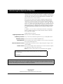
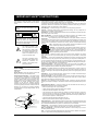
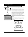
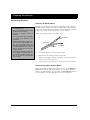
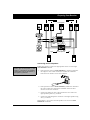
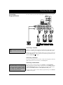
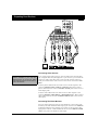
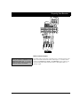
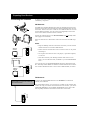
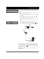
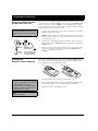
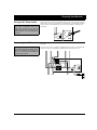
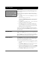
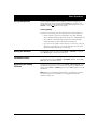
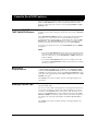
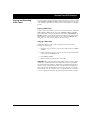
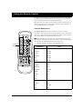
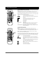
Cat. No. 31-3045 Audio/Video Receiver STAV-3780 DOLBY SURROUND P R O L O G I C STAV-3780 AUDIO/VIDEO RECEIVER STANDBY 5-D THEATER DOLBY PRO LOGIC VIRTUAL SRS DSP MODE DSP VCR TAPE 1 OSR DVD/TV LD/SAT CD FM/AM PHONO TAPE 2 MONITOR DIGITAL SIGNAL PROCESSOR DVD 5.1CH VOLUME POWER LOUDNESS MUTING MPX MODE DIRECT TUNING SELECT MEMORY PHONES CLASS SELECT 5X100WATT EQUAL POWER OUTPUT SPEAKERS TONE STATION L TUNING Owner’s Manual BALANCE R MIN MAX Please read before using this equipment. Introducing the Optimus STAV-3780 Your Optimus STAV-3780 Audio/Video Receiver operates as the perfect control center for your audio/video system. It combines 100 watts-perchannel of clean power with modern styling. It provides connections for one tape deck, one VCR, two audio/video sources, a turntable, a CD player, and two TV’s or video monitors. Your receiver has special sound options. Dolby Pro Logic ® Surround Sound delivers movie theater sound for audio/video programs (especially those encoded with Dolby Surround Sound signals). DSP Effects creates a listening environment that simulates a concert hall, jazz club, theater, or a dance hall. Virtual Dolby Surround uses TruSurround technology to provide a three-dimensional sound field using only the front left and right speakers. 5-D Theater provides clear dynamic sound effect by sending audio signals through the rear channel to simulate stereo sound. In addition, you can connect a multi-channel decoder or DVD player with 5.1-channel output so that all five channels and the subwoofer have independent signals. Additional features include: Digital-Synthesized Tuner Precisely tunes to AM and FM stations. 30 Memory Locations Let you store and recall the frequencies for up to 30 AM/FM stations. Automatic Tuning Searches for the next available AM/FM station. Tape Monitoring Lets you listen to the actual recording as you record, if your tape deck has a tape-monitoring feature. Built-In Protection Circuits Automatically turn off the receiver to help avoid power surges or short circuit damage. Remote Control Lets you use a single remote control for the receiver and other compatible components connected to the receiver. Note: The remote control requires two AA batteries (not supplied). We recommend you record the receiver’s serial number here. The number is on the receiver’s back panel. Serial Number:_____________________________________________ Note to the Cable TV System Installer: This reminder is provided to call the CATV system installer’s attention to Article 820-40 of the National Electrical Code that provides guidelines for proper grounding and, in particular, specifies that the cable ground shall be connected to the grounding system of the building as close to the point of cable entry as practical. 1999 Tandy Corporation. All Rights Reserved. RadioShack and Optimus are registered trademarks used by Tandy Corporation. 2 IMPORTANT SAFETY INSTRUCTIONS This receiver is made and tested to meet exacting safety standards. It meets both UL and FCC requirements. WARNING: To reduce the risk of fire or shock hazard, do not expose this product to rain or moisture. CAUTION RISK OF ELECTRIC SHOCK. DO NOT OPEN. ! CAUTION: TO REDUCE THE RISK OF ELECTRIC SHOCK, DO NOT REMOVE COVER OR BACK. NO USER-SERVICEABLE PARTS INSIDE. REFER SERVICING TO QUALIFIED PERSONNEL. This symbol is intended to alert you to the presence of uninsulated dangerous voltage within the product’s enclosure that might be of sufficient magnitude to constitute a risk of electric shock. Do not open the product’s case. This symbol is intended to inform you that important operating and maintenance instructions are included in the literature accompanying this product. ! CAUTION Power Lines—Locate an outdoor antenna away from power lines. Nonuse Periods—Unplug the receiver’s power cord when you will not use it for extended periods. Outdoor Antenna Grounding—If an outside antenna or cable system is connected to the receiver, ground the antenna or cable system so as to provide some protection against voltage surges and built-up static charges. Article 810 of the National Electrical Code, ANSI/NFPA 80, provides information about proper grounding of the mast and supporting structure, grounding of the lead-in wire to an antenna discharge unit, size of grounding conductors, location of antennadischarge unit, connection to grounding electrodes, and requirements for the grounding electrode. See the example below. Careful attention is devoted to quality standards in the manufacture of your receiver, and safety is a major factor in its design. However, safety is also your responsibility. This section lists important information that will help you properly use and enjoy your receiver and accessories. Read all the included safety and operating instructions before using your receiver. Follow them closely, and retain them for future reference. Heed Warnings — Follow all warnings on the product and in the operating instructions. Cleaning — Unplug this product from the wall outlet before cleaning. Use only a damp cloth for cleaning. Do not use liquid or aerosol cleaners. Attachments — Do not use attachments/accessories not recommended by the product manufacturer, as they might create a hazard. Water and Moisture — Do not use this product near water (for example, near a bathtub, washbowl, kitchen sink, or laundry tub; in a wet basement; or near a swimming pool). Accessories — Do not place this product on an unstable cart, stand, tripod, bracket, or table. The product may fall, causing serious injury to a child or adult, and serious damage to the product. Use only with a cart, stand, tripod, bracket, or table recommended by the manufacturer or sold with the product. Follow the manufacturer's instructions for mounting, and use a recommended mounting accessory. Carts — Move the product on a cart carefully. Quick stops, excessive force, and uneven surfaces may cause the product/cart to overturn. Ventilation — Slots and openings in the cabinet provide ventilation, ensure reliable operation, and protect from overheating. Do not block or cover these openings, and do not place the product on a bed, sofa, rug, or other similar surface. Do not place the product in a built-in bookcase or rack unless it provides proper ventilation as specified by the manufacturer. Power Sources — Operate this product using only the power source indicated on its marking label. If you are not sure of your home's power type, consult your product dealer or local power company. Polarization — This product is equipped with a polarized AC line plug (a plug having one blade wider than the other). This plug will fit in the power outlet only one way. This is a safety feature. If you cannot insert the plug fully into the outlet, try reversing the plug. If the plug still doesn't fit, contact your electrician to replace your obsolete outlet. Do not defeat the safety purpose of the polarized plug. If you need an extension, use a polarized cord. Power-Cord Protection — Route power-supply cords so they are not likely to be walked on or pinched by items placed on or against them, paying particular attention to cords at plugs, convenience receptacles, and the point where they exit from the product. Lightning — For added protection for this product during a lightning storm, or when it is left unattended and unused for long periods of time, unplug it from the wall outlet and disconnect the antenna or cable system. This will prevent damage to the product due to lightning and power-line surges. Overloading — Do not overload wall outlets, extension cords, or integral convenience receptacles, as this can result in a risk of fire or electric shock. Objects and Liquids — Never push objects of any kind into this product through openings, as they may touch dangerous voltage points or short out parts that could result in a fire or electric shock. Never spill liquid of any kind on the product. Servicing — Do not attempt to service this product yourself, as opening or removing covers may expose you to dangerous voltage or other hazards. Refer all servicing to qualified service personnel. Damage Requiring Service — Unplug this product from the wall outlet and refer servicing to qualified service personnel under the following conditions: • When the power-supply cord or plug is damaged. • If liquid has been spilled or objects have fallen into the product. • If the product has been exposed to rain or water. Antenna Lead-In Wire • If the product has been dropped or damaged in any way. Ground Clamp Electric Service Equipment Antenna Discharge Unit (NEC Section 810-20) Grounding Conductors (NEC Section 810-21) Grounding Clamps NEC -- National Electrical Code • If the product does not operate normally by following the operating instructions. Adjust only those controls that are covered by the operating instructions, as an improper adjustment of other controls may result in damage and will often require extensive work by a qualified technician to restore the product to normal operation. Power Service Grounding Electrode System (NEC Article 250, Part H) • When the product exhibits a distinct change in performance. Replacement Parts — When replacement parts are required, be sure the service technician uses replacement parts specified by the manufacturer or having the same characteristics as the original part. Unauthorized substitutions may result in fire, electric shock, or other hazards. Safety Check — Upon completion of service or repairs to this product, ask the service technician to perform safety checks to determine that the product is in proper operating condition. Wall or Ceiling Mount — The product should be mounted to a wall or ceiling only as recommended by the manufacturer. Heat — The product should be situated away from heat sources such as radiators, heat registers, stoves, or other products (including amplifiers) that produce heat. 3 Contents Preparing Your Receiver . . . . . . . . . . . . . . . . . . . . . . . . . . . . . . . . . . . . . . . . . . . . . . . . . . . . . . . . . . . . . . 5 Positioning Speakers . . . . . . . . . . . . . . . . . . . . . . . . . . . . . . . . . . . . . . . . . . . . . . . . . . . . . . . . . . . . . . . . 5 Connecting Speakers . . . . . . . . . . . . . . . . . . . . . . . . . . . . . . . . . . . . . . . . . . . . . . . . . . . . . . . . . . . . . . . 6 Connecting Program Sources . . . . . . . . . . . . . . . . . . . . . . . . . . . . . . . . . . . . . . . . . . . . . . . . . . . . . . . . . 9 Connecting the Antennas . . . . . . . . . . . . . . . . . . . . . . . . . . . . . . . . . . . . . . . . . . . . . . . . . . . . . . . . . . . 12 Using One Remote Control for More than One Unit . . . . . . . . . . . . . . . . . . . . . . . . . . . . . . . . . . . . . . . . 14 Installing the Remote Control’s Batteries . . . . . . . . . . . . . . . . . . . . . . . . . . . . . . . . . . . . . . . . . . . . . . . . 14 Using the AC Power Outlet . . . . . . . . . . . . . . . . . . . . . . . . . . . . . . . . . . . . . . . . . . . . . . . . . . . . . . . . . . 15 Connecting to AC Power . . . . . . . . . . . . . . . . . . . . . . . . . . . . . . . . . . . . . . . . . . . . . . . . . . . . . . . . . . . . 15 Basic Operation . . . . . . . . . . . . . . . . . . . . . . . . . . . . . . . . . . . . . . . . . . . . . . . . . . . . . . . . . . . . . . . . . . . 16 Tuning the Radio . . . . . . . . . . . . . . . . . . . . . . . . . . . . . . . . . . . . . . . . . . . . . . . . . . . . . . . . . . . . . . . . . 17 Using MPX Mode . . . . . . . . . . . . . . . . . . . . . . . . . . . . . . . . . . . . . . . . . . . . . . . . . . . . . . . . . . . . . . . . . . 18 Adjusting Balance . . . . . . . . . . . . . . . . . . . . . . . . . . . . . . . . . . . . . . . . . . . . . . . . . . . . . . . . . . . . . . . . . 18 Using Headphones . . . . . . . . . . . . . . . . . . . . . . . . . . . . . . . . . . . . . . . . . . . . . . . . . . . . . . . . . . . . . . . . 19 Muting the Receiver . . . . . . . . . . . . . . . . . . . . . . . . . . . . . . . . . . . . . . . . . . . . . . . . . . . . . . . . . . . . . . . 19 Loudness Control . . . . . . . . . . . . . . . . . . . . . . . . . . . . . . . . . . . . . . . . . . . . . . . . . . . . . . . . . . . . . . . . . 19 Bypassing the Sound Controls . . . . . . . . . . . . . . . . . . . . . . . . . . . . . . . . . . . . . . . . . . . . . . . . . . . . . . . . 19 Cassette Deck/VCR Features . . . . . . . . . . . . . . . . . . . . . . . . . . . . . . . . . . . . . . . . . . . . . . . . . . . . . . . . . 20 Using the VCR/TAPE 1 and TAPE 2 MONITOR Buttons . . . . . . . . . . . . . . . . . . . . . . . . . . . . . . . . . . . . 20 Monitoring a Program Source . . . . . . . . . . . . . . . . . . . . . . . . . . . . . . . . . . . . . . . . . . . . . . . . . . . . . . . . 20 Dubbing a Cassette Tape . . . . . . . . . . . . . . . . . . . . . . . . . . . . . . . . . . . . . . . . . . . . . . . . . . . . . . . . . . . 20 Playing and Recording Video Tapes . . . . . . . . . . . . . . . . . . . . . . . . . . . . . . . . . . . . . . . . . . . . . . . . . . . . 21 Using Advanced Sound Options . . . . . . . . . . . . . . . . . . . . . . . . . . . . . . . . . . . . . . . . . . . . . . . . . . . . . . . 22 Sound Mode Adjustments (Remote Control Only) . . . . . . . . . . . . . . . . . . . . . . . . . . . . . . . . . . . . . . . . . 23 Using the Remote Control . . . . . . . . . . . . . . . . . . . . . . . . . . . . . . . . . . . . . . . . . . . . . . . . . . . . . . . . . . . 25 Troubleshooting . . . . . . . . . . . . . . . . . . . . . . . . . . . . . . . . . . . . . . . . . . . . . . . . . . . . . . . . . . . . . . . . . . . 34 Care and Maintenance . . . . . . . . . . . . . . . . . . . . . . . . . . . . . . . . . . . . . . . . . . . . . . . . . . . . . . . . . . . . . . 35 The FCC Wants You to Know . . . . . . . . . . . . . . . . . . . . . . . . . . . . . . . . . . . . . . . . . . . . . . . . . . . . . . . . . 36 Specifications . . . . . . . . . . . . . . . . . . . . . . . . . . . . . . . . . . . . . . . . . . . . . . . . . . . . . . . . . . . . . . . . . . . . . 37 Index to Features by Control Name . . . . . . . . . . . . . . . . . . . . . . . . . . . . . . . . . . . . . . . . . . . . . . . . . . . . . 39 4 Preparing Your Receiver Caution: Make all the necessary connections before you plug in or turn on the receiver. Positioning Speakers a L R Midway Point Between Speakers b a=b Normal Listening Point • Surround speakers generally sound best if you position them above ear level. • To avoid picture interference of a nearby TV, use magnetically shielded speaker systems. This is particularly important for the center speaker since it is usually located closest to the TV. Where you place your speakers (not supplied) can make a noticeable difference in your system’s sound. The guidelines in this section will help you choose the best locations. After you use your receiver for a while, you might want to try different locations for your speakers. Bass response depends largely on speaker location. For strong bass, place the speakers in the corners of the room. If you want even stronger bass, place the speakers directly on the floor. If the bass is too strong, move the speakers slightly away from the corners of the room, or raise them 6 to 18 inches off the floor. You can buy speaker stands at your local RadioShack store. The distance between the speakers should be about the same as the distance between the normal listening point and the point halfway between the speakers. If you place the speakers too close together, you reduce the stereo separation. If you place them too far apart, you reduce the bass effect and create a hole in the middle of the sound. Most speakers have a tweeter dispersion angle of about 60 degrees. Ideally, your listening position should be just inside the overlap area of the tweeter dispersion. You can angle the speakers toward you for better stereo effect. To position your speakers for surround sound, place the front speakers at the front of your listening area, and place the (rear) surround speakers behind or to the sides of the listening point (see “Using Advanced Sound Options” on Page 22). Place the center speaker above, below, or behind the TV. If you place it beside the TV, the picture may not coincide with the sound. Front Left Speaker Center Speaker Front Front Right Speaker Listening Area Rear Rear Left Speaker Rear Right Speaker 5 Preparing Your Receiver Connecting Speakers Preparing the Speaker Wires Follow these guidelines when you select and connect speakers. • Only connect speakers that are rated at between 6 and 16 Ohms. • Be sure you properly connect all speakers. Speaker wire consists of two conductors (individual wires) encased in insulation and is usually color-coded or marked with a ridge along one side so you can identify each conductor. Use these markings as a guide to help you properly connect the speakers to your receiver. Follow these steps to prepare the speaker wires. • Do not connect two pairs of speakers to a single set of terminals at the same time. • Optimus and other high-quality speakers have color-coded speaker terminals (red for positive polarity and black for negative polarity). Use these color-coded terminals as a guide to help you properly connect the speakers to the receiver. • Use 16-gauge (or larger) speaker wire for all speaker connections, and consider possible speaker locations before you decide how much speaker wire you need. Wire Strands Speaker Wire Wire Strands Conductor 1. Cut the speaker wires to the necessary length. 2. Separate the wires about 4 inches on each end. 3. Using a wire stripper, carefully strip about 3/4 inch of insulation from the end of each conductor. 4. Twist the end of each conductor to secure any loose wire strands. Setting the Impedance Selector Switch Before proceeding to speaker connection, be sure to set the IMPEDANCE SELECTOR switch to the appropriate position. If you connect speakers with 6- to 8-ohm impedance, set the switch to 6~LESS THAN 8 W position. If you are using 8- to 16-ohm impedance, set it to 8~16 Ω position. 6 Preparing Your Receiver Right Front Speakers Right Left Left Center Speaker AUDIO IN R L R L CENTER PRE OUT CAUTION: SPEAKER IMPEDANCE 6Ω OR 8Ω ~16Ω / SPEAKER PRE OUT SUB WOOFER AUDIO IN CENTER SPEAKER SURROUND SPEAKERS R L A A B B R L FRONT SPEAKERS Amplified Subwoofer Right Surround Speakers Left R Connecting the Front Speakers Note: Be sure you connect the receiver’s right and left positive (+) and negative (–) terminals to the speaker’s corresponding right and left positive (+) and negative (–) terminals. Follow these steps to connect the right speaker to the receiver’s right FRONT SPEAKERS terminals. 1. Press open the receiver’s FRONT SPEAKERS R (+) red lever and insert the ridged or color-coded conductor’s end into the small hole. Press the lever closed to secure the conductor. 2. Press open the receiver’s FRONT SPEAKERS R (–) black lever and insert the other conductor’s end into the small hole. Press the lever closed to secure the conductor. 3. Connect the ridged or color-coded conductor’s loose end to the right speaker’s positive (+) terminal. 4. Connect the remaining loose conductor to the right speaker’s negative (–) terminal. Repeat Steps 1–4 to connect the left speaker to the receiver’s SPEAKERS left terminals. FRONT 7 Preparing Your Receiver Preparing Your Receiver Connecting Surround-Sound Speakers You can connect a pair of speakers to the receiver for surround-sound programs. Follow the steps in “Connecting the Front Speakers” to connect the speakers to the SURROUND SPEAKERS terminals. Connecting the Center Speaker The center speaker gives additional ambience to surround sound. Follow the steps in “Connecting the Front Speakers” to connect the center speaker to the CENTER SPEAKER terminals. Or, if you are intending to use the amplified speaker as your center speaker, connect CENTER PRE OUT to its line-level input. You can also connect this jack to the audio input of your TV. Connecting a Subwoofer Amplifier Your receiver includes a line-level subwoofer output. Connecting a subwoofer to your system dramatically extends bass response for incredible richness and depth. When you listen to surround-sound programs, a subwoofer enhances your home theater experience by realistically recreating the rumble of an earthquake, the bone-jarring percussion of a cannon, and more. To use the subwoofer output, simply connect SUBWOOFER PRE OUT to an amplified subwoofer’s line-level input or to an amplifier to which you have connected a subwoofer. RadioShack stores sell a variety of suitable subwoofers and amplifiers. 8 Preparing Your Receiver Connecting Program Sources You can connect up to five external program sources to your receiver. DVD 5.1CH INPUT SURROUND CENTER CENTER PRE OUT L VIDEO OUT TO MONITOR TV PRE OUT SURROUND SUB SUB WOOFER R WOOFER CONTROL 2 1 OUT VIDEO IN IN IN IN IN OUT IN OUT L L R R PHONO PLAY DVD/ TV LD/ DVD 5.1CH SAT FRONT CD REC PLAY REC TAPE2 MONITOR VCR/TAPE1 SIGNAL GND L R R L L R R L L L R L L R L R L R R R REC OUT PUT LINE PLAY REC L L L R R REC INPUT PLAY OUTPUT LINE PLAY R REC INPUT PLAY OUTPUT CD Turntable CD Player Cassette Deck Cassette Deck Connecting a Turntable Note: Use shielded audio cables with phono connectors for all audio connections. Connect a turntable with a magnetic cartridge only. Some older turntables use a ceramic-type cartridge that does not work with this system. Connect the turntable’s left and right cables to the receiver’s L (left) and R (right) PHONO IN jacks. Then connect the turntable’s ground wire to the receiver’s SIGNAL GND terminal. Connecting a CD Player To connect a CD player to the receiver, connect the CD player’s left and right output jacks to the receiver’s L and R CD IN jacks. Connecting Cassette Decks Note: If you place the cassette deck directly above, below, or to the left of the receiver, the receiver could interfere with the cassette deck’s operation. If possible, position the cassette deck to the right or away from the receiver. You can connect cassette decks to the VCR/TAPE 1 and TAPE 2 MONITOR jacks. Connect the cassette deck’s output jacks to the VCR/TAPE 1 IN PLAY or TAPE 2 MONITOR IN PLAY jacks. Then, connect the cassette deck’s input jacks to the VCR/TAPE 1 OUT REC or TAPE 2 MONITOR OUT REC jacks. You can connect a third cassette deck (for playback only) to the DVD/TV IN or LD/SAT (audio) jacks. 9 Preparing Your Receiver DVD 5.1CH INPUT SURROUND CENTER CENTER PRE OUT L VIDEO OUT TO MONITOR TV PRE OUT SURROUND SUB WOOFER SUB R WOOFER CONTROL 2 1 V OUT VIDEO IN IN IN IN IN OUT IN OUT L R PHONO DVD/ TV LD/ DVD 5.1CH SAT FRONT CD PLAY REC PLAY REC TAPE2 MONITOR VCR/TAPE1 V SIGNAL GND V V V L R L R V L R R V L R L R L V L R L V R V VIDEO IN AUDIO OUT VIDEO OUT AUDIO OUT VIDEO OUT VIDEO AUDIO REC PLAY L L L OUT R R R IN REC INPUT PLAY OUTPUT DVD TV Monitor DVD VCR LD Player VCR Connecting Video Sources Note: If your VCR is monaural, use a Yadapter (available at your local RadioShack store) to connect the VCR’s audio output to both the L and R audio inputs on the receiver. If you connect three video sources, such as VCRs, laser disc (LD) players, or digital video disc (DVD) players to your receiver, you can use the receiver to select each video source. You can also use the receiver to easily record from these video sources to the source connected to VCR/ TAPE 1. Connect phono cables from each video source’s audio outputs to the receiver’s VCR/TAPE 1 IN PLAY, LD/SAT IN, or DVD/TV IN jacks. Then connect phono cables from the receiver’s VCR/TAPE 1 OUT REC jacks to the source’s audio input jacks. Connect video cables from each video source’s video outputs to the receiver’s VCR/TAPE 1, LD/SAT VIDEO IN, or DVD/TV VIDEO IN jacks. Then connect video cables from the receiver’s VCR/TAPE 1 VIDEO OUT jack to the source’s video input. Connecting TVs/Video Monitors You can connect either two TV’s or video monitors to the receiver. The monitor (or TV with baseband video input) you connect to the VIDEO OUT terminal can monitor any program you connect to the receiver’s video input jacks. Connect a video cable from the receiver’s VIDEO OUT TO MONITOR TV 1 or 2 jack to the monitor’s video input. 10 Preparing Your Receiver DVD 5.1CH INPUT SURROUND CENTER CENTER PRE OUT L VIDEO OUT TO MONITOR TV PRE OUT SURROUND SUB SUB WOOFER R WOOFER CONTROL 2 1 OUT VIDEO IN IN IN IN IN OUT IN OUT L R PHONO CD PLAY DVD/ TV LD/ DVD 5.1CH SAT FRONT REC VCR/TAPE1 PLAY REC TAPE2 MONITOR SIGNAL GND R L L R L V R L V R AUDIO OUT VIDEO OUT SURROUND CENTER OUT OUT L L R R SUBWOOFER OUT DVD DVD DVD 5.1-Channel Inputs Note: Subwoofer output is obtained only when you connect a subwoofer to the SUBWOOFER PREOUT jack. If you use a passive subwoofer (without an amplifier), subwoofer output is not obtained. The STAV-3780 accepts both 2-channel and 5.1-channel input for DVD players and multi-channel decoders. Selecting the 5.1-channel mode enables the SURROUND L/R, CENTER, and SUBWOOFER output jacks for signal processing with multi-channel decoder or DVD player with 5.1channel output. Preparing Your Receiver 11 Preparing Your Receiver Connecting the Antennas In many areas, the supplied indoor AM loop and FM antennas provide satisfactory reception. AM Antennas Assemble the supplied AM antenna’s base by swinging the base in the direction of the arrow and inserting the antenna’s bottom tabs into the base’s slot. If the receiver is in a rack or on a shelf and there is no room for the AM loop antenna, use two screws (not supplied) to mount the base on the wall or another location as shown. Attach the antenna wires to the nals (upper two terminals). AM LOOP ANTENNA and (ground) termi- Place the antenna on a flat surface and rotate it for the best AM reception. Notes: ANTENNA AM AM Loop Antenna LOOP ANTENNA FM UNBAL 75Ω • Keep the AM loop antenna connected even when you use another indoor antenna or an outdoor AM antenna. • Ensure that the antenna does not touch the receiver or any other metal object. • Do not place the antenna near a CD player, a personal computer, or a TV set. • If the wire between your AM loop antenna and receiver is too short, you can add extra wire, available at your local RadioShack store. Outdoor AM Antenna ANTENNA AM LOOP ANTENNA You can also use an optional RadioShack shortwave antenna kit (Cat. No. 278-758), which makes an excellent outdoor AM antenna. Connect the outdoor AM antenna wire to the receiver’s AM terminal, as shown. AM Loop Antenna FM UNBAL 75Ω FM Antennas Note: For the best results, use 75-ohm coaxial cable to connect an outdoor antenna to the receiver. Connect the supplied FM antenna to the shown, then extend it. FM UNBAL 75Ω terminal as For better FM reception, you can also use a rabbit-ear TV antenna (for indoor use only). To connect the TV antenna to the receiver, you need a VHF/UHF/FM splitter (not included). RadioShack stores carry a full line of quality antennas and antenna connection accessories. ANTENNA AM LOOP ANTENNA FM UNBAL 75Ω 12 Preparing Your Receiver Warning: To prevent injury, read and follow all cautions and warnings that accompany the outdoor antenna. For the best radio reception, use an outdoor antenna. Follow these steps to connect an outdoor FM antenna to the receiver using 75Ω coaxial cable. Note: If your antenna has 300Ω twin-lead cable, consult your local RadioShack store for the correct adapter. 1. Disconnect the supplied FM antenna from the receiver’s 75Ω terminal. FM UNBAL 2. With a stripping tool, remove about 1 1/2 inches of the outdoor antenna cable’s outer insulation to expose the cable’s shielding. 3. Fold back the shielding from the inner insulation. 4. Remove about 1 inch of the inner insulation from around the center wire. Caution: The cable’s shielding should only touch the terminal. 5. Pull the shielding to one side. Connect the center wire to the receiver’s FM UNBAL 75Ω terminal. Twist the shielding to secure any loose wire strands, and connect it to the FM UNBAL 75Ω terminal. Inner Insulation Outer Insulation Center Wire Shielding Outdoor FM Antenna ANTENNA AM LOOP ANTENNA Shielding FM UNBAL 75Ω Center Wire Note: Grounding is not necessary for reception, but we recommend it for better FM reception and to avoid damage from lightning when you use an outdoor FM antenna. Use a separate piece of thick polyvinyl insulated wire to connect the terminal to the building’s power service grounding electrode system. Warning: Never connect a wire to a gas pipe for grounding since sparks might ignite the gas. 13 Preparing Your Receiver Using One Remote Control for More than One Unit Note: When you plug the cable into a component’s CONTROL IN jack, that component’s remote sensor does not function. If you also have an Optimus professional series CD player, VCR, or cassette deck with the OSR mark ( ), you can connect its CONTROL IN jack to the receiver so you can control all of your equipment with a single remote control. You can also use the other component’s remote control by pointing it at the receiver’s front panel. 1. Connect each component to the receiver as shown in “Connecting Program Sources” on Page 9. Note: You must connect the audio cables between the receiver and the other audio accessory to use your receiver’s remote control to control the accessory. CONTROL CONTROL IN OUT OUT Receiver Other Component with OSR Mark Remote Control To the CONTROL IN jack of Another Component having the OSR Mark Installing the Remote Control’s Batteries Cautions: 2. Connect the cable supplied with the CD player, VCR, or cassette deck to the receiver’s CONTROL OUT jack and the other component’s CONTROL IN jack. 3. When you want to control more than one other component using the receiver’s remote control, daisy-chain the CONTROL OUT and CONTROL IN connections as shown. Your remote control requires two AA batteries (not included) for power. For the best operation and longest life, we recommend alkaline batteries, available at your local RadioShack store. 1. Press and slide open the battery compartment cover. • Use only fresh batteries of the required size and recommended type. 2. Place two fresh AA batteries in the compartment as indicated by the polarity symbols (+ and –) marked in the compartment. • Always remove old or weak batteries. Batteries can leak chemicals that can damage electronic circuits. 3. Replace the battery compartment cover. Note: If the remote’s range is reduced, replace the batteries. 14 Preparing Your Receiver Using the AC Power Outlet Caution: Do not connect appliances with high power consumption, such as a heater, iron, monitor, or TV, to this AC outlet. Doing so can cause a risk of overheating and fire, and could damage the receiver. Your receiver has an AC power outlet that you can use to power an electronic device, such as a turntable, cassette deck, or VCR. This switched outlet turns on and off with the receiver and provides a maximum of 100 watts. AC 120V 60Hz CAUTION: SEE INSTRUCTION MANUAL CAUTION: 8 ~16Ω/ SPEAKER DO NOT CONNECT TV SET OR MONITOR. SWITCHED 100W MAX 0.8A MAX 6~LESS THAN 8Ω/ SPEAKER IMPEDANCE SELECTOR Connecting to AC Power Warning: To prevent electric shock, do not use this polarized plug with an extension cord, receptacle, or other outlet unless you can fully insert the blades to prevent blade exposure. AC OUTLET Before you plug in the receiver’s power cord, double check all other connections. To power the receiver, plug the supplied power cord into a standard AC outlet. The power cord’s plug is polarized and fits only one way. R L CAUTION: SPEAKER IMPEDANCE 6Ω OR 8Ω ~16Ω / SPEAKER L R CENTER SPEAKER SURROUND SPEAKERS R AC 120V 60Hz L A A B B R L FRONT SPEAKERS CAUTION: SEE INSTRUCTION MANUAL 8 ~16Ω/ SPEAKER 6~LESS THAN 8Ω/ SPEAKER IMPEDANCE SELECTOR CAUTION: DO NOT CONNECT TV SET OR MONITOR. SWITCHED 100W MAX 0.8A MAX AC OUTLET 15 Basic Operation Warning: To prevent possible hearing loss, turn VOLUME to MIN before you turn on the receiver or change the program sources. After you turn on the receiver or change the program source, adjust VOLUME to a comfortable listening level. The controls on the remote control work the same as the buttons on the receiver’s front panel, though some are labeled differently. Follow these steps to use the receiver. 1. Press POWER to turn on the receiver’s power. 2. Press SPEAKERS on the front panel (if necessary) so SP on the display. A appears 3. Select a program source. To tune to a radio station, see “Tuning the Radio” on Page 17. Note: If you select a source while TAPE 2 MONITOR is engaged, TAPE 2 flashes five times on the display, reminding you to disengage the TAPE 2 MONITOR function. To listen to signals from the component connected to TAPE 2 MONIpress TAPE 2 MONITOR so TAPE 2 appears on the display. TOR, To listen to a source other than one connected to TAPE 2 MONITOR, be sure TAPE 2 does not show on the display. If necessary, press TAPE 2 MONITOR so TAPE 2 disappears. Then press VCR/TAPE 1, DVD/TV or LD/SAT (digital video disc/laser disc), CD, AM/FM (tuner), or PHONO, or repeatedly press FUNC on the remote control, to display the desired program source. 4. Adjust VOLUME clockwise to increase the volume or counterclockwise to decrease it. Or, you can use MASTER VOLUME –/+ on the remote control. 5. Adjust the bass, treble, or balance to suit your listening preference. Repeatedly press TONE/BALANCE on the front of the receiver until the item you want to adjust appears on the display — TREB, BASS, or BALANCE. Then press until you get the desired sound. TONE For more detail on adjusting the sound balance, see “Adjusting Balance” on Page 18. 6. When you finish using the receiver, press Note: To find out what a particular button or control is used for, see Page 25 (for the remote control) or Page 39 (for the front panel) to find the page where the button or control is described. 16 POWER to turn it off. Basic Operation Tuning the Radio Notes: • A class is a group of up to 10 station frequencies. • For weak signals, we recommend manual tuning. Your receiver has four types of electronic tuning — manual, automatic, direct access, and memory. Manual and Automatic Tuning Follow these steps to manually or automatically tune to stations. Note: If none of the tuning buttons on the remote control operate, press TUNER first. 1. Press FM/AM on the front panel (or repeatedly press FUNC on the remote control so the band name and frequency appears on the display) to select the tuner. 2. Press FM/AM again (BAND on the remote control) to select the desired band. The receiver tunes to and displays the frequency last selected in that band. If A, B, or C and a single digit number appear to the left of the station frequency, press TUNING SELECT (BAND on the remote control) so the band name (AM or FM) appears. 3. To manually select the next lower or higher frequency, press once to manually select the next lower or higher freTUNING quency. Or, hold down the button to rapidly change frequencies, and release it. To automatically search for the next lower or higher station, hold until the display starts to change, then release down TUNING it. The receiver searches down or up the band to the next strong station. Notes: • TUNED appears when you receive a strong signal. • at the top of the frequency range or If you press TUNING TUNING at the bottom of the frequency range, the display returns to the other end of the range. Direct Access Tuning (Remote Control Only) Follow these steps to directly enter a frequency. 1. Press TUNER to select the tuner. Then press BAND to select the desired band. The receiver tunes to and displays the frequency last selected in that band. 2. Press DIRECT ACCESS. _ _ _ _ with the first _ _ flashing. __ _ _ appears on the display 3. Enter the desired frequency using the number buttons. Notes: • If you enter an invalid frequency (for example, entering 828), the receiver tunes to the closest valid frequency (830 kHz). • If you do not press a key within 5 seconds, the receiver exits direct access tuning. Start over at Step 2. 17 Basic Operation Memory Tuning Notes: • If you store a frequency in a memory that already contains a frequency, you replace the previous frequency. • If your receiver is disconnected from AC power for several days, it loses all the stored frequencies. Memory tuning lets you store up to 30 AM or FM frequencies in three different classes (10 frequencies in each class), then quickly tune to a class and station. Follow these steps to store a station in a memory location using the front panel controls. (You cannot store a station in a memory using the remote control.) 1. Press FM/AM to select the tuner, then press FM/AM again to select the desired band. 2. Tune to the frequency you want to store. If desired, press MPX MODE (MPX on the remote control) for FM stereo or monaural sound (see “Using MPX Mode”). This setting is also stored in memory. 3. Press MEMORY. The class (A, B, or C) and _ _ (for the channel number) flash on the display for about 5 seconds. 4. Press press CLASS until the class you want (A, B, or C) appears, then until the channel number you want appears. STATION In about 5 seconds, the class and channel number light steadily, indicating the receiver stored the frequency. To tune to a stored station, press CLASS so the desired class number appears, then repeatedly press to select the channel. Or, STATION you can directly enter the channel number using that number’s key on the remote control. Using MPX Mode To receive FM stations in stereo, press MPX MODE so MONO disappears from the display. STEREO appears when you receive an FM broadcast in stereo. You can improve the reception of weak FM stations by pressing MPX until MONO appears. This reduces noise while you listen to a weak FM station, but you get monaural instead of stereo sound. MODE Adjusting Balance The TONE/BALANCE control lets you adjust the sound balance between the left and right speakers. If you properly position the speakers and your listening area is centered between them, the center control setting is usually best (see “Positioning Speakers” on Page 5). For an unusual speaker placement, adjust the speaker balance as follows: 1. Press FM/AM to select the tuner, then press FM/AM again to select the FM band. 2. Press MPX MODE so MONO appears. The sound is monaural instead of stereo, so each speaker delivers the same output. 3. Repeatedly press SELECT on the front of the receiver until BALANCE appears. Then press L BALANCE R until you hear the sound coming equally from each speaker when you are in the listening area. 4. Press 18 MPX MODE so MONO disappears from the display. Basic Operation Using Headphones To listen with headphones (not supplied), insert the headphones’ 1/4inch plug into the receiver’s front panel PHONES jack. To silence the speakers and listen with headphones without disturbing others, press appears on the display. SPEAKER so only SP Listening Safely To protect your hearing, note the following when using headphones. • Set the volume to its lowest setting before you begin listening. After you begin listening, adjust the volume to a comfortable level. • Do not listen at extremely high volume levels. Extended highvolume listening can lead to permanent hearing loss. • Once you set the volume, do not increase it. Over time, your ears adapt to the volume level, so a volume level that does not cause discomfort might still damage your hearing. Muting the Receiver To temporarily mute the sound, press MUTING. --MUTING -- appears. Press MUTING again to restore the audio level. Loudness Control To increase the high and low ranges of sounds for improved audio at a low listening level, press LOUDNESS so LOUDNESS appears. Press LOUDNESS again to turn off this feature. Bypassing the Sound Controls To bypass your receiver’s sound controls (BASS, TREBLE, BALANCE, or any special sound options) so you can hear the audio at its original tonal quality, press DIRECT so DIRECT appears. Press DIRECT again to turn off this feature. Note: When you turn off the bypass feature, you will have to reselect any desired special sound options (see “Using Advanced Sound Options” on Page 22). 19 Cassette Deck/VCR Features You can connect two cassette decks to the receiver. Selecting either VCR/ TAPE 1 or TAPE 2 MONITOR lets you hear the playback from the cassette deck you connected to the receiver’s corresponding (VCR/TAPE 1or TAPE 2 MONITOR) jacks. Using the VCR/TAPE 1 and TAPE 2 MONITOR Buttons Press VCR/TAPE 1. VCR appears on the display. You hear the playback from the cassette deck or VCR you connected to the receiver’s VCR/TAPE 1 IN jacks. Press TAPE 2 MONITOR. TAPE 2 appears on the display along with the last program source you selected. You can hear playback or monitor a recording from the cassette deck you connected to the receiver’s TAPE 2 MONITOR jacks. The TAPE 2 MONITOR REC jacks continue to output sound from the previously selected source after you press TAPE 2 MONITOR. To return to the previous source, press disappears. TAPE 2 MONITOR again so TAPE 2 Notes: • If you press TAPE 2 MONITOR when that cassette deck is neither playing nor recording, the receiver mutes the current audio source. To hear the audio source, press TAPE 2 MONITOR so TAPE 2 disappears from the display. • Do not press TAPE 2 MONITOR while you are recording on the deck connected to TAPE 2 MONITOR REC. Doing so interrupts the recording for about 1 second. Monitoring a Program Source The receiver sends the audio of the program source you select— VCR/TAPE (tuner), or PHONO —to the VCR/TAPE 1 OUT/REC (audio) and TAPE 2 MONITOR OUT/REC jacks. If you select VCR/TAPE 1, DVD/TV, or LD/SAT, the video program is sent to the VIDEO OUT TO MONITOR TV 1 and 2 jacks. The video program input from DVD/TV or LD/SAT is also sent to VCR1/ TAPE1REC video jack. 1, DVD/TV, LD/SAT, CD, FM/AM The VOLUME control does not affect the level of the signal going to the tape decks. Dubbing a Cassette Tape You can copy (dub) a cassette tape from one cassette deck to another using the STAV-3780. You can use either deck as the playback or recording deck. However, if you want to monitor the cassette deck during dubbing, use the deck connected to the VCR/TAPE 1 jacks as the source, and the deck you connected to the TAPE 2 REC jacks as the recording deck. Then press TAPE 2 MONITOR so TAPE 2 and the last program source you selected appear on the display. See “Using the VCR/TAPE 1 and TAPE 2 MONITOR Buttons.” The VOLUME control does not affect the level of the signal going to the tape decks. 20 Cassette Deck/VCR Features Playing and Recording Video Tapes You can connect two video sources to the receiver. If you connect a VCR to the VCR/TAPE 1 and DVD/TV or LD/SAT audio and video jacks, you can copy video cassette tapes from one VCR to another and monitor the dubbing process. Playing a Video Tape To play a video tape, load the tape into the VCR connected to either VCR/ or LD/SAT. Press the button (VCR/TAPE 1, DVD/TV, or LD/SAT) that corresponds to the jack the VCR is connected to. VCR, DVD/TV, or LD/SAT appears on the display. Follow the VCR’s instructions to begin playback. If you connected a monitor to the receiver’s TO MONITOR TV 1 and 2 jacks, you can view the program on that monitor. TAPE 1, DVD/TV, Copying a Video Tape Follow these steps to copy a video tape from one VCR to another through the STAV-3780. 1. Insert the tape you want to copy into the VCR connected to or LD/SAT. DVD/TV 2. Insert a blank tape (or one you want to record over) into the VCR connected to the VCR/TAPE 1 jack. 3. Press DVD/TV or LD/SAT. 4. Begin recording and playback on the VCRs. Important: Most material performed in public, such as concerts, plays, and movies, or distributed on prerecorded video tapes is copyrighted. The unauthorized recording or duplication of copyrighted material is a violation of the copyright laws of most countries and such duplication may result in fines, imprisonment, or both. Note, however, that in the United States, it is not a violation of U.S. copyright laws for a consumer to record a broadcast television program for private (in-home) viewing. 21 Using Advanced Sound Options Your receiver has four special sound options: Dolby Pro Logic Surround, Dolby 3CH Logic, DSP Effect, and Dolby Virtual. These special options enhance the sound from a connected program source. Notes: • To get the full benefit from programs encoded with Dolby Surround Sound, you need a stereo audio/video source. • Dolby Surround does not operate correctly if the signal passes through a graphic equalizer. If you connected an equalizer to the TAPE 2 MONITOR jacks, do not select TAPE 2 MONITOR when you listen to Dolby Surround signals. Dolby Pro Logic Surround Dolby Pro Logic Surround puts you in the middle of the action. The center- and rear-channel speakers add incredible realism by directing the sound to the appropriate speakers, making you feel like you are really there. Pro Logic is the standard for surround sound systems. Dolby 3CH LOGIC produces a more spacious sound field than is possible with ordinary stereo playback by sending the rear channel’s sound to the front left and right speakers. Select 3CH LOGIC when you play a Dolby Surround Sound program and do not have rear speakers. To turn on Dolby Pro Logic Surround or Dolby 3CH Logic, press PRO LOGIC until PRO LOGIC appears on the display, then press SURROUND on the remote control followed by CENTER MODE to select NORMAL, WIDE, PHANTOM, or 3CH LOGIC. See “Sound Mode Adjustments (Remote Control Only)” on Page 23 for information about each of these options. Virtual Dolby Surround (Dolby Virtual/SRS) Note: The tone controls do not work when you select VIRTUAL mode. Virtual lets you enjoy programs encoded with Dolby Surround while using only two front speakers. SRS creates a surround sound environment from a material recorded in stereo. Select SRS 1 for the source that has broad frequency range such as classical or live music. Use SRS 2 for pop and jazz recording for smaller audio session atmosphere. To turn on Virtual Dolby Surround, press VIRTUAL/SRS (VIRTUAL on the remote control) until the desired option — VIRTUAL, SRS1, or SRS2 — appears. Press VIRTUAL/SRS (VIRTUAL on the remote control) to turn off this feature. DSP Effect You can choose one of five DSP effects — HALL, JAZZ, DANCE, THEATER 1, THEATER 2, or DIALOG. Hall simulates a large concert hall, best suited for classical music. Jazz provides the acoustic effects generally heard in jazz clubs. Dance gives the effect of a discotheque. Both theater modes provide the effect of a movie theater. THEATER 1 sounds like a large movie theater. THEATER 2 seems like a smaller theater. Try each setting to find the best effect for your programs. DIALOG enhances the frequencies of human voice, so you can hear the dialogs more clearly. To turn on a DSP effect, press DSP MODE until the desired option appears on the display. Press DSP MODE to turn off the DSP mode. DSP OFF appears on the display. 22 Using Advanced Sound Options 5-D Theater 5-D Theater provides clearer and more dynamic sound effects by outputting audio signals through the rear channel to simulate the stereo sound, compared with a standard surround system which provides only monaural signals to the rear speakers. Press 5-D THEATER to turn this feature on/off. DVD 5.1-Channel Input Together with a multi-channel decoder or DVD player with 5.1-channel output, you can feed sound to all five speaker channels. The front L/R, surround L/R, center speaker channels, and the subwoofer have independent signals for enhanced rich sound. The subwoofer channel contains bass sound only and the frequency range is smaller than the other speaker channels, so it is called 5.1-channel system. Note: This feature is active only when you select DVD/TV function. Press DVD/TV on the front panel to select the function, then press DVD/TV again. Each time you press the button, the mode alternates between normal and 5.1CH operations. To use this feature using the remote control, press then press 5.1CH. DVD/TV followed by SURROUND, Note: When you use 5.1CH sound mode, you cannot use DOLBY VIRTUAL/ SRS, PRO LOGIC, 5-D THEATER, and DIRECT modes. If you press a button for any of these modes, DVD 5.1CH flashes on the display as a reminder. Sound Mode Adjustments (Remote Control Only) Center Mode Setting Note: If you do not use a center speaker, the monaural signals are only reproduced if you select PHANTOM. The center mode setting affects the center channel’s bass signals. It operates only when you select the Dolby Pro Logic Surround or Dolby 3CH Logic mode. On the remote control, press SURROUND then CENTER MODE. Each time you press CENTER MODE, the setting changes: NORMAL, WIDE, PHANTOM, or 3CH LOGIC. NORMAL — For a small center speaker. The front left and right speakers play the center-channel bass sounds. WIDE — For a medium or large center speaker. The center speaker plays the center-channel bass sounds. PHANTOM — For no center speaker. All center-channel sound comes from the front left and right speakers. 3CH LOGIC — For no rear speakers. The rear channel’s sound is sent to the front left and right speakers. 23 Using Advanced Sound Options Test Tone Notes: • You must use the remote control to make these sound adjustments. • Use the VOLUME control to adjust the overall sound level. The test tone lets you balance the signal levels between all your speakers. To adjust the levels, see “Center Level” and “Rear Level.” To turn on the test tone, select one of the surround sound modes (PRO LOGIC, or 5.1-CH) then press SURROUND. Then press TEST TONE. The receiver sounds a 2-second tone from the front left, center, front right, and surround (rear) speakers, in sequence. FLch, Cch, FRch, SRch, and SLch appear as the test tone sounds. The center test tone sounds and Cch appears only when you select Normal, Wide, or 3CH LOGIC. If you select 3CH LOGIC, the receiver sounds the 2-second tone from the left, center, and right speakers, in sequence. Press TEST TONE again to turn off this feature. Center Level Press – CENTER LEVEL + to adjust the center speaker sound level. Rear Levels Press – REAR RIGHT LEVEL + or ers’ sound level. – REAR LEFT LEVEL + to adjust the rear speak- Subwoofer Level Press – SW LEVEL + to adjust the subwoofer sound level. This control works in any sound mode. Note: Depending on the sound mode you selected, some speaker level controls do not work. For example, when you select 3CH LOGIC, – REAR RIGHT LEVEL + or – REAR LEFT LEVEL + does not work. Delay Time In the Dolby Pro Logic Surround modes (except 3CH Logic), the receiver slightly delays the sound going to the rear speakers. You can change this delay time from 15 to 30 milliseconds (ms) in 5 ms steps. Adjust the delay time for the best surround effect. As a general guide, each step corresponds to 3-5 feet in distance. For example, if the surround speakers are 6 feet closer to you than the front speakers, try selecting 20 ms setting. Press SURROUND, then hold down DELAY TIME to change the delay time. The receiver displays the selected time. Effect Level With DSP, you can change the delay time to alter the sound effect from 10 to 90. Press SURROUND, then hold down – EFFECT + to change the effect level. The effect can vary depending on the source program. 24 Using the Remote Control The remote control works up to a distance of about 23 feet, and within a 30-degree angle on either side of the receiver. Point the control at the receiver’s front panel and press the desired button(s). Many buttons on the remote control work the same as buttons on the receiver’s front panel. Use these buttons exactly as you would use the corresponding buttons on the receiver. CONTROL MODE Buttons The CONTROL MODE buttons select the device you want to control. The remote control can operate the basic functions of your other audio/ video device. Follow these steps to program the remote control with the correct manufacturer’s code number for the device. CONTROL MODE Note: Some brands have more than one code listed in the charts. If a code does not work with your device, try another. The listed codes might not work with all models from the listed manufacturers. 1. Find the code for your device in the following chart. Control Mode DVD Brand Code JVC 004,010 Panasonic 003,009 Pioneer 000,006 Samsung 005,011 Sony 002,008 Toshiba 001,007 LD Brand Code Kenwood 103 Mitsubishi 100 Panasonic 105,106 Philips 104 Pioneer 100 RCA 107 Sony 101 SAT Brand Codes Pioneer 200 RCA 201,203 Sony 202 25 Using the Remote Control VCR Brand Code Fisher 410,426,412,427,425,420 Goldstar 411,409 Hitachi 408,401,406,436,434 JVC 428,430,429,408,414,431,407 Magnavox 414,408,426,403 Mitsubishi 409,420,421,422,423,424,408,407 Optimus 408,432,433,402,418,419 Panasonic 408,432,433 Pioneer 400 RCA 401,406,408,414,405,413,411,415 Sanyo 410,412,425,435 Sharp 402,418,419 Sony 416,417,404,408 Toshiba 405,409,426 Zenith 403,404,417 TAPE Brand 26 Code Denon 810 Fisher 813 JVC 802,815 Kenwood 804,807 Onkyo 809,808 Optimus 800 Pioneer 800 Sony 801,806 TEAC 805 Technics 803 Yamaha 811,812,816 Using the Remote Control CD Brand Code Denon 309 JVC 303 Kenwood 310,321,311 Marantz 323,312,324 Onkyo 320,308,307 Optimus 300 Philips 312,322 Pioneer 300 RCA 302,319,313 Sanyo 313 Sony 301,316,317,318 TEAC 305,306,327,324,325 Technics 304,326 Yamaha 315,314,328 TV Brand Code GE 601,608,610,611,617,602,628,618 Goldstar 610,623,621,602 Grandiente 635 Hitachi 606,610,624,625,618 JVC 613,623 Magnavox 607,610,603,612,629 Mitsubishi 609,610,602,621 Panasonic 608,622,607 Philips 607 Pioneer 600 RadioShack 610,623,621,602 RCA 601,610,615,616,617,618 Sanyo 621,614 Sharp 602,619,627 Sony 604 Toshiba 605,602,626,621 Zenith 603,620 27 Using the Remote Control CATV Brand Code Jerrold 711,701,702,712,704,713,703,714,716,715 Pioneer 700 S.A. 705,706,708,709 Zenith 707,717,710 MD Brand Code Denon 904 Kenwood 903 Pioneer 900 Sharp 902 Sony 901 2. While holding down PRESET, press the button for the the device you want to set. The PRESET RECALL indicator lights. The labels on the CONTROL MODE buttons are for your convenience only. You can program any device to any button. For example, if you do not have a DVD player but you wish to program your second VCR, use DVD to enter the code for second VCR. 3. Point the remote control to the device desired and enter the threedigit code. The remote control sends power on/off signal for the device. If the code is correct, the device should turn on or off. If the device does not function, repeat Steps 2 and 3 and try other codes for the manufacturer. If it still does not function, you must use the original remote control supplied with your device. Notes: es: • The remote control keeps the code you programmed for short periods of time, allowing you to replace the batteries without losing the codes. However, if the remote control fails to operate after you replace the batteries, re-enter the codes. • You can clear all the programmed codes if necessary. Press PRESET, DISC, and POWER (on the top row, not RECEIVER POWER at the bottom) at the same time for about three seconds until the PRESET RECALL indicator blinks three times. 28 Using the Remote Control Receiver/Amplifier Operation Before operation, press STATION BAND TUNING TUNER TUNER to select receiver/amplifier operation. Tunes to the next higher or lower memory location. Selects the AM or FM tuner band. Tunes to radio stations. MPX Selects the FM reception mode. CLASS Selects the memory class. DIRECT ACCESS Allows direct input of the station frequency. Number Buttons Select the corresponding memory station. During Direct Access, enter the station’s frequency. – SW LEVEL+ Controls the sound level of the subwoofer when pressed after SURROUND. – REAR RIGHT LEVEL+ Controls the sound level of the rear speakers when pressed after SURROUND. CONTROL MODE TEST TONE Sounds test tones from each speaker when pressed after SURROUND. Receiver/ Amplifier Buttons – REAR LEFT LEVEL+ Controls the sound level of the rear speakers when pressed after SURROUND. CENTER MODE Selects among the three center modes or 3CH Logic when pressed after SURROUND in Dolby Pro-Logic mode. – CENTER LEVEL + Controls the sound level of the center speaker when pressed after SURROUND. DELAY TIME Sets the rear-channel delay for Dolby Pro Logic Surround programs when pressed after SURROUND. – EFFECT + Adjusts the level of DSP mode. SURROUND Sets the remote control into the surround setup mode. PRO LOGIC Selects Dolby Pro Logic Surround. DSP MODE Selects the DSP mode; HALL, JAZZ, DANCE, THEATER 1, or THEATER 2. MUTING Silences the receiver. Press again to restore the sound to its previous level. VIRTUAL Selects virtual surround mode; DOLBY VIRTUAL, SRS1, or SRS2. 5-D THEATER Selects 5-D Theater mode. + MASTER VOLUME – Adjusts the system’s volume. RECEIVER POWER Turns the receiver on and off. FUNC Selects a program source (VCR, PHONO, tuner, CD, DVD/TV, or LD/SAT). Repeatedly press until the display shows the desired program source. DIRECT Bypasses the receiver’s audio control circuits. Press again to restore the previous settings. 29 Using the Remote Control CD Player/MD Recorder Operation Note: You must have connected the CD player to both of your receiver’s CONTROL OUT and audio jacks or programmed the code for your CD player/MD recorder into the remote control for these functions to work. CONTROL MODE CD Before operation, press CD (or the one connected to your CD player/MD recorder) to select CD player operation. CD Player Buttons Turns the CD player/MD recorder on and off. POWER / | Returns to the beginning of the current track or advances to the next track. | Rapidly advances backward/forward within a track. / Press to pause play. Press again to resume. Stops playback. Plays the disc. Number Buttons Selects track. +10 Enters 10 of the track number. For example, to enter track 15, press +10 then 5 (might not work with some CD players). DISC (CD player only) Selects discs in a multi-play CD changer. (DISC might not work with some CD players.) Cassette Deck Operation Note: You must have connected the cassette deck to both your receiver’s CONTROL OUT and audio jacks or programmed the code for your cassette deck into the remote control for these functions to work. CONTROL MODE TAPE Cassette Deck Buttons Before operation, press TAPE (or the one connected to your cassette deck) to select cassette deck operation. The remote control operates a single cassette deck and Deck 2 on a dual cassette deck. To operate Deck 1 on a dual cassette deck, use the buttons shown in parentheses (these buttons do not work with all decks). Turns on/off the cassette deck. POWER Press to play the other side of an auto-reverse cassette deck. (7 ) (8 ) / (9 ) Quickly locates and plays the beginning of recorded material during play. Or, when the tape is stopped, rapidly searches forward or backward to locate a specific section of the tape. 30 (0 ) Press to temporarily stop playback/recording. Press again to resume. (+10) Stops playback/recording. (DISC) Press to start normal playback. Using the Remote Control DVD Player Operation Note: You must have programmed the code for your DVD player into the remote control for these functions to work. DVD Before operation, press DVD (or the one connected to your DVD player) to select DVD player operation. Turns on/off the DVD player. POWER Press to switch the audio input. On some DVD players, pressing this button switches the angle. CONTROL MODE | / | / Returns to the beginning of the current chapter/track or advances to the next chapter/track. Rapidly advances backward/forward within a chapter/track. Press to pause play. Press again to resume. On some DVD players, press to pause the playback so you can view a single frame (freeze-frame operation). DVD Buttons Stops playback. Plays the disc. DISC Turns the menu on/off. The number buttons and +10 work differently depending on the type of DVD players you are using. The two basic systems are: A. Some models use the buttons as the normal number buttons. Number Buttons Selects chapter/track. +10 Enters 10 of the chapter/track number. For example, to enter chapter/track 15, press +10 then 5. B. Some models use the buttons as the cursor buttons. 2 Up arrow (▲) 4 Left arrow( ) 5 ENTER 6 Right arrow ( ) 8 Down arrow (▼) 9 MENU 0 RETURN +10 TITLE 31 Using the Remote Control LD Player Operation Note: You must have programmed the code for your LD player into the remote control for these functions to work. CONTROL MODE Before operation, press LD (or the one connected to your LD player) to select LD player operation. LD Player Buttons LD Turns the LD player on and off. POWER / | | / Returns to the beginning of the current chapter/track or advances to the next chapter/track. Rapidly advances backward/forward within a chapter/track. Press to pause play. Press again to resume. On some LD players, press to pause the playback so you can view a single frame (freeze-frame operation). Stops playback. Plays the disc. Number Buttons Selects chapter/track. +10 Enters 10 of the track number. For example, to enter track 15, press +10 then 5 (might not work with some LD players). DISC Selects the side of a disc. VCR Operation Note: You must have programmed the code for your VCR into the remote control for these functions to work. CONTROL MODE Before operation, press VCR operation. VCR Buttons POWER CHANNEL VCR VCR (or the one connected to your VCR) to select Turns on/off the VCR. Press to change the VCR’s tuner channel. Press to switch the VCR antenna output, VCR’s tuner output or direct signal from antenna to use TV’s tuner. / Quickly locates and plays the beginning of recorded material during play. Or, when the tape is stopped, rapidly searches forward or backward to locate a specific section of the tape. Press to temporarily stop playback/recording. Press again to resume. On some VCRs, press to pause the playback so you can view a single frame (freeze-frame operation). Stops playback/recording. (DISC) 32 Press to start normal playback. Number Buttons Selects channel directly (might not work with some VCRs). +10 With some VCRs, you might need to press this to enter the channel you selected with number buttons. Using the Remote Control TV and CATV Operation Note: You must have programmed the code for your TV or CATV into the remote control for these functions to work. Before operation, press TV (or the one connected to your TV or CATV) to select TV/CATV operation. TV POWER CHANNEL TV FUNC (TV only) TV VOL Number Buttons Turns on/off the TV or CATV. Press to change the tuner channel. Selects the TV’s input mode, antenna or line input. Adjusts the volume. Selects channel directly. On some TVs, you might need to press DISC after entering the channel number. On some models, the functions of the buttons are different. CONTROL MODE POWER Turns the power on/off. Moves cursor left.( ) Moves cursor up.(▲) | Moves cursor right. ( ) TV/ CATV/ SAT Moves cursor down. (▼) Decreases volume. Increases volume. | Selects the TV’s input mode, antenna or line input. ENTER - enters the selected cursor position. Number Buttons Selects channel directly. DISC Turns the menu on/off. Satellite Receiver Operation Note: You must have programmed the code for your SAT receiver to the remote control for these functions to work. Before operation, press TV (or the one that you connected to your SAT receiver) to select SAT receiver operation. POWER Turns the power on. Moves cursor left.( ) Moves cursor up.(▲) | Moves cursor right. ( ) Moves cursor down. (▼) | Turns the power off. ENTER - enters the selected cursor position. Number Buttons Selects channel directly. DISC Turns the menu on/off. 33 Troubleshooting If the receiver is not working as it should, the following suggestions might help. If you follow the suggestions in this chart and the receiver still does not work properly, contact your local RadioShack store for assistance. Problem Power does not turn on. Cause Suggestion Power cord is disconnected. Plug in the power cord. Protection circuit is activated. Unplug the power cord, then plug it in again. The receiver does not respond to button presses. Static discharge has affected the receiver. Unplug the power cord, then plug it in again. (If static electricity is a problem, use the remote control as much as possible.) No sound. Incorrect connections. Check and correct the connections. The mute function is activated. Press MUTING. The volume is turned down. Turn up the volume. Speaker wires are disconnected. Connect the speaker wires. Speakers are turned off. Press SPEAKER so SP A appears on the display. TAPE 2 function is engaged. Press TAPE 2 so TAPE 2 clears from the display. The selected video source is not set correctly. Correct the problem with the selected video source. Incorrect connections. Check and correct the connections. Station not correctly tuned. Adjust tuning. Antenna not connected. Connect the antenna. FM antenna still coiled or is not pointing in the correct direction. Stretch both ends of the antenna taut and reposition the antenna. AM loop antenna not pointing in the correct direction. Adjust the AM loop antenna. No picture when you select a video source. High noise level. Noise is coming from another electri- Try using an AC line noise filter to reduce the noise. cal appliance. Automatic tuning does not stop when searching for stations. Stations are too weak. Use a better antenna. Cannot make copies of video tapes. Tapes are protected by a copy protection method. You cannot make a good copy. Video connections are incorrect. Check and correct the connections. Remote is set to other device. Press the CONTROL MODE button for the device to control. Code is not correctly set. Try re-programming the remote control. Batteries are weak. Replace the batteries. Cassette deck or CD player is not compatible. The feature only works with Optimus Professional Series components. Control cable is not plugged in. Properly connect the control cable. Audio cables are not plugged in. Properly connect the audio cables. Remote control does not work. Remote does not control cassette deck or CD player. 34 Care and Maintenance Your Optimus STAV-3780 Audio/Video Receiver is an example of superior design and craftsmanship. The following suggestions will help you care for the receiver so you can enjoy it for years. Keep the receiver dry. If it gets wet, wipe it dry immediately. Liquids can contain minerals that can corrode the electronic circuits. Handle the receiver gently and carefully. Dropping it can damage its circuit boards and can cause the receiver to work improperly. Use and store the receiver and its remote control only in normal temperature environments. Temperature extremes can shorten the life of electronic devices, damage batteries, and distort or melt plastic parts. Keep the receiver away from dust and dirt, which can cause premature wear of parts. Wipe the receiver with a damp cloth occasionally to keep it looking new. Do not use harsh chemicals, cleaning solvents, or strong detergents to clean the receiver. Use only fresh batteries of the recommended size and type in the remote control. Always remove old or weak batteries. They can leak chemicals that can destroy electronic circuits. Modifying or tampering with your receiver’s internal components can cause a malfunction and might invalidate the receiver’s warranty and void your FCC authorization to operate it. If the receiver is not operating as it should, take it to your local RadioShack store for assistance. 35 The FCC Wants You to Know Your receiver might cause radio or TV interference even when it is operating properly. To determine whether your receiver is causing the interference, turn off your receiver. If the interference goes away, your receiver is causing it. Try to eliminate the interference by: • Moving your radio or TV away from the receiver • Connecting your receiver to an outlet that is on a different electrical circuit from the radio or TV • Contacting your local RadioShack store for help If you cannot eliminate the interference, the FCC requires that you stop using your receiver. 36 Specifications Amplifier Front Channel Average Power Output . . . . . . . . . . . . . . . . . . . . . . . . . . . . . . 100 Watts per Channel into 8 Ohms From 20 to 20,000 Hz, With No More than 0.09% Total Harmonic Distortion Measured Pursuant to the Federal Trade Commission’s Trade Regulation Rule on Amplifier Output Power Claims Front Channel Surround Power Output . . . . . . . . . . . . . . . . 100 Watts per Channel (1 kHz, 0.9% THD, 8 Ohms) Center Channel Surround Power Output . . . . . . . . . . . . . . . . . . . . . . . . . 100 Watts (1 kHz, 0.9% THD, 8 Ohms) Continuous Rear Surround Power Output . . . . . . . . . . . . . . 100 Watts per Channel (1 kHz, 0.9% THD, 8 Ohms) Input Sensitivity/Impedance Phono . . . . . . . . . . . . . . . . . . . . . . . . . . . . . . . . . . . . . . . . . . . . . . . . . . . . . . . . . . 2.8 mV/47 kOhms CD, DVD/TV, LD/SAT, VCR/TAPE 1, TAPE 2 Monitor . . . . . . . . . . . . . . . . . . . . . 200 mV/47 kOhms Phono Overload Level (0.1% THD, 1 kHz) . . . . . . . . . . . . . . . . . . . . . . . . . . . . . . . . . . . . . . . . . . . . . . . . 100 mV Frequency Response Phono . . . . . . . . . . . . . . . . . . . . . . . . . . . . . . . . . . . . . . . . . . . . . . . . . . . 20 Hz to 20,000 Hz ±0.3 dB CD, DVD/TV, LD/SAT, VCR/TAPE 1, TAPE 2 Monitor . . . . . . . . . . . . . . 5 Hz to 100,000 Hz +0/–3 dB Output Level/Impedance VCR/TAPE 1 REC, TAPE 2 Monitor REC . . . . . . . . . . . . . . . . . . . . . . . . . . . . . . . 200 mV/2.2 kOhms Tone Controls Bass . . . . . . . . . . . . . . . . . . . . . . . . . . . . . . . . . . . . . . . . . . . . . . . . . . . . . . . . . . . . . . . . . . . . . . . . . . . . . . . . ±8 dB (150 Hz) Treble . . . . . . . . . . . . . . . . . . . . . . . . . . . . . . . . . . . . . . . . . . . . . . . . . . . . . . . . . . . . . . . . . . . . . . . . . . . . . . . ±8 dB (10 kHz) Loudness . . . . . . . . . . . . . . . . . . . . . . . . . . . . . . . . . . . . . . . . . . . . . . . +7 dB/+6 dB (100 Hz/10 kHz) Signal-to-Noise Ratio (IHF, Short Circuited, A Network) Phono . . . . . . . . . . . . . . . . . . . . . . . . . . . . . . . . . . . . . . . . . . . . . . . . . . . . . . . . . . . . . . . . . . . . 72 dB CD, DVD/TV, LD/SAT, VCR/TAPE 1, TAPE 2 Monitor . . . . . . . . . . . . . . . . . . . . . . . . . . . . . . . . 96 dB Signal-to-Noise Ratio (EIA, at 1 Watt, 1 kHz) Phono . . . . . . . . . . . . . . . . . . . . . . . . . . . . . . . . . . . . . . . . . . . . . . . . . . . . . . . . . . . . . . . . . . . . 75 dB CD, DVD/TV, LD/SAT, VCR/TAPE 1, TAPE 2 Monitor . . . . . . . . . . . . . . . . . . . . . . . . . . . . . . . . 79 dB Video Section Input Sensitivity/Impedance VCR/TAPE 1, DVD/TV, LD/SAT . . . . . . . . . . . . . . . . 1 Volt Peak-to-Peak/75 Ohms Output Level/Impedance VCR/TAPE 1, MONITOR TV . . . . . . . . . . . . . . . . . . . . . . . 1 Volt Peak-to-Peak/75 Ohms Frequency Response VCR/TAPE 1, DVD/TV, LD/SAT to Monitor . . . . . . . . . . . . . . . . . . 5 Hz to 7 MHz +0/–3 dB Signal-to-Noise Ratio . . . . . . . . . . . . . . . . . . . . . . . . . . . . . . . . . . . . . . . . . . . . . . . . . . . . . . . . . . . . . . . . . 55 dB Crosstalk . . . . . . . . . . . . . . . . . . . . . . . . . . . . . . . . . . . . . . . . . . . . . . . . . . . . . . . . . . . . . . . . . . . . . . . . . . 55 dB 37 Specifications FM Tuner Frequency Range . . . . . . . . . . . . . . . . . . . . . . . . . . . . . . . . . . . . . . . . . . . . . . . . . . . . . . . . . . . . 87.5 to 108 MHz Usable Sensitivity . . . . . . . . . . . . . . . . . . . . . . . . . . . . . . . . . . . . . . . . . . . Mono: 13.2 dBf, IHF (1.3 µV/75 Ohms) 50 dB Quieting Sensitivity Mono . . . . . . . . . . . . . . . . . . . . . . . . . . . . . . . . . . . . . . . . . . . . . . . . . . . . . . . . . . . . . . . . . . . 20.2 dBf Stereo . . . . . . . . . . . . . . . . . . . . . . . . . . . . . . . . . . . . . . . . . . . . . . . . . . . . . . . . . . . . . . . . . . 38.6 dBf Signal-to-Noise Ratio Mono . . . . . . . . . . . . . . . . . . . . . . . . . . . . . . . . . . . . . . . . . . . . . . . . . . . . . . . . . . . . 73 dB (at 85 dBf) Stereo . . . . . . . . . . . . . . . . . . . . . . . . . . . . . . . . . . . . . . . . . . . . . . . . . . . . . . . . . . . 70 dB (at 85 dBf) Distortion . . . . . . . . . . . . . . . . . . . . . . . . . . . . . . . . . . . . . . . . . . . . . . . . . . . . . . . . . . . . . . . Stereo: 0.5% (1 kHz) Alternate Channel Selectivity . . . . . . . . . . . . . . . . . . . . . . . . . . . . . . . . . . . . . . . . . . . . . . . . . . . 60 dB (400 kHz) Stereo Separation . . . . . . . . . . . . . . . . . . . . . . . . . . . . . . . . . . . . . . . . . . . . . . . . . . . . . . . . . . . . . . 40 dB (1 kHz) Frequency Response . . . . . . . . . . . . . . . . . . . . . . . . . . . . . . . . . . . . . . . . . . . . . . . . . . . 30 Hz to 15 kHz (±1 dB) Antenna Input . . . . . . . . . . . . . . . . . . . . . . . . . . . . . . . . . . . . . . . . . . . . . . . . . . . . . . . . . . 75 Ohms Unbalanced AM Tuner Frequency Range . . . . . . . . . . . . . . . . . . . . . . . . . . . . . . . . . . . . . . . . . . . . . . . . . . . . . . . . . . . . 530 to 1700 kHz Sensitivity (IHF, Loop Antenna) . . . . . . . . . . . . . . . . . . . . . . . . . . . . . . . . . . . . . . . . . . . . . . . . . . . . . . 350 µV/m Selectivity . . . . . . . . . . . . . . . . . . . . . . . . . . . . . . . . . . . . . . . . . . . . . . . . . . . . . . . . . . . . . . . . . . . . . . . . . 25 dB Signal-to-Noise Ratio . . . . . . . . . . . . . . . . . . . . . . . . . . . . . . . . . . . . . . . . . . . . . . . . . . . . . . . . . . . . . . . . . 50 dB General Power Requirements . . . . . . . . . . . . . . . . . . . . . . . . . . . . . . . . . . . . . . . . . . . . . . . . . . . . . . . 120 Volts AC, 60 Hz Power Consumption . . . . . . . . . . . . . . . . . . . . . . . . . . . . . . . . . . . . . . . . . . . . . . . . . . . . . 280 Watts, 410 VA (UL) AC Outlet Ratings Switched . . . . . . . . . . . . . . . . . . . . . . . . . . . . . . . . . . . . Total 100 Watts (0.8 Amps) Maximum Dimensions (HWD) . . . . . . . . . . . . . . . . . . . . . . . . . . . . . . . . . . . . . . . . . . . . . . . . . . 6 1/4 × 16 9/16 × 14 3/4 Inches (158 × 420 × 374 mm) Weight . . . . . . . . . . . . . . . . . . . . . . . . . . . . . . . . . . . . . . . . . . . . . . . . . . . . . . . . . . . . . . . . . . . . . . . . 19 lb 14 oz (9 kg) Specifications are typical; individual units might vary. Specifications are subject to change and improvement without notice. 38 Index to Features by Control Name This table lists the control and indicator names found on the front of your receiver, along with the page number where the control or indicator is discussed. To find a description for the buttons on the remote control, see “Using the Remote Control” on Page 25. Control Page 5-D THEATER 23 TONE/BALANCE 16, 18 CD 16 CLASS 18 DIRECT 19 DOLBY PRO LOGIC 22 DSP MODE 22 DVD/TV 16 FM/AM 17 LD/SAT 15 LOUDNESS 19 MEMORY 18 MPX MODE 18 MUTING 19 PHONES 19 PHONO 16 POWER 16 SELECT 16, 17 SPEAKERS 16, 19 STATION TAPE 2 MONITOR TUNING 18 16, 20 17 TUNING SELECT 17 VCR/TAPE 1 16, 20 VIRTUAL/SRS 22, 24 VOLUME 16 39 Limited Two-Year Warranty This product is warranted by RadioShack against manufacturing defects in material and workmanship under normal use for two (2) years from the date of purchase from RadioShack companyowned stores and authorized RadioShack franchisees and dealers. EXCEPT AS PROVIDED HEREIN, RadioShack MAKES NO EXPRESS WARRANTIES AND ANY IMPLIED WARRANTIES, INCLUDING THOSE OF MERCHANTABILITY AND FITNESS FOR A PARTICULAR PURPOSE, ARE LIMITED IN DURATION TO THE DURATION OF THE WRITTEN LIMITED WARRANTIES CONTAINED HEREIN. EXCEPT AS PROVIDED HEREIN, RadioShack SHALL HAVE NO LIABILITY OR RESPONSIBILITY TO CUSTOMER OR ANY OTHER PERSON OR ENTITY WITH RESPECT TO ANY LIABILITY, LOSS OR DAMAGE CAUSED DIRECTLY OR INDIRECTLY BY USE OR PERFORMANCE OF THE PRODUCT OR ARISING OUT OF ANY BREACH OF THIS WARRANTY, INCLUDING, BUT NOT LIMITED TO, ANY DAMAGES RESULTING FROM INCONVENIENCE, LOSS OF TIME, DATA, PROPERTY, REVENUE, OR PROFIT OR ANY INDIRECT, SPECIAL, INCIDENTAL, OR CONSEQUENTIAL DAMAGES, EVEN IF RadioShack HAS BEEN ADVISED OF THE POSSIBILITY OF SUCH DAMAGES. Some states do not allow the limitations on how long an implied warranty lasts or the exclusion of incidental or consequential damages, so the above limitations or exclusions may not apply to you. In the event of a product defect during the warranty period, take the product and the RadioShack sales receipt as proof of purchase date to any RadioShack store. RadioShack will, at its option, unless otherwise provided by law: (a) correct the defect by product repair without charge for parts and labor; (b) replace the product with one of the same or similar design; or (c) refund the purchase price. All replaced parts and products, and products on which a refund is made, become the property of RadioShack. New or reconditioned parts and products may be used in the performance of warranty service. Repaired or replaced parts and products are warranted for the remainder of the original warranty period. You will be charged for repair or replacement of the product made after the expiration of the warranty period. This warranty does not cover: (a) damage or failure caused by or attributable to acts of God, abuse, accident, misuse, improper or abnormal usage, failure to follow instructions, improper installation or maintenance, alteration, lightning or other incidence of excess voltage or current; (b) any repairs other than those provided by a RadioShack Authorized Service Facility; (c) consumables such as fuses or batteries; (d) cosmetic damage; (e) transportation, shipping or insurance costs; or (f) costs of product removal, installation, set-up service adjustment or reinstallation. This warranty gives you specific legal rights, and you may also have other rights which vary from state to state. RadioShack Customer Relations, Dept. W, 100 Throckmorton St., Suite 600, Fort Worth, TX 76102 We Service What We Sell 3/97 RadioShack A Division of Tandy Corporation Fort Worth, Texas 76102 04A99 <ARB7194-A> Printed in Indonesia