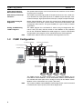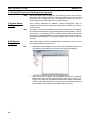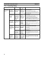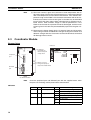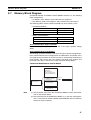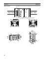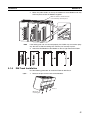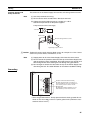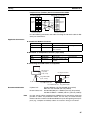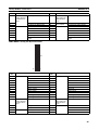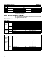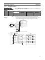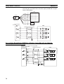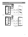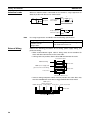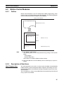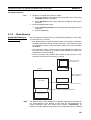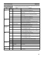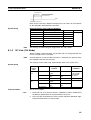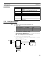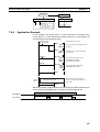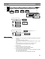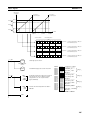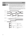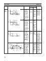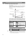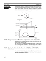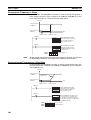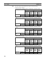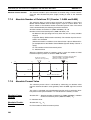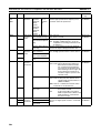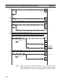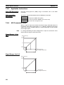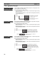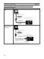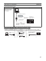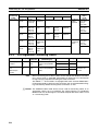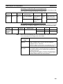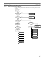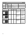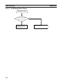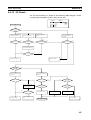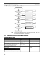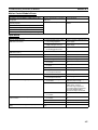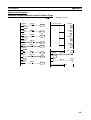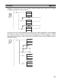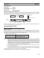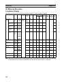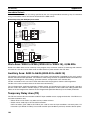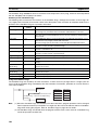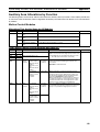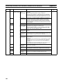
1
Cat. No. O010-E1-01 FQM1 Series FQM1-CM001 FQM1-MMP21 FQM1-MMA21 Flexible Motion Controller OPERATION MANUAL FQM1 Series FQM1-CM001 FQM1-MMP21 FQM1-MMA21 Flexible Motion Controller Operation Manual Produced November 2004 iv Notice: OMRON products are manufactured for use according to proper procedures by a qualified operator and only for the purposes described in this manual. The following conventions are used to indicate and classify precautions in this manual. Always heed the information provided with them. Failure to heed precautions can result in injury to people or damage to property. !DANGER Indicates an imminently hazardous situation which, if not avoided, will result in death or serious injury. !WARNING Indicates a potentially hazardous situation which, if not avoided, could result in death or serious injury. !Caution Indicates a potentially hazardous situation which, if not avoided, may result in minor or moderate injury, or property damage. OMRON Product References All OMRON products are capitalized in this manual. The word “Unit” is also capitalized when it refers to an OMRON product, regardless of whether or not it appears in the proper name of the product. The abbreviation “Ch,” which appears in some displays and on some OMRON products, often means “word” and is abbreviated “Wd” in documentation in this sense. The abbreviation “CM” means Coordinator Module and the abbreviation “MM” means Motion Control Module. Visual Aids The following headings appear in the left column of the manual to help you locate different types of information. Note Indicates information of particular interest for efficient and convenient operation of the product. 1,2,3... 1. Indicates lists of one sort or another, such as procedures, checklists, etc. OMRON, 2004 All rights reserved. No part of this publication may be reproduced, stored in a retrieval system, or transmitted, in any form, or by any means, mechanical, electronic, photocopying, recording, or otherwise, without the prior written permission of OMRON. No patent liability is assumed with respect to the use of the information contained herein. Moreover, because OMRON is constantly striving to improve its high-quality products, the information contained in this manual is subject to change without notice. Every precaution has been taken in the preparation of this manual. Nevertheless, OMRON assumes no responsibility for errors or omissions. Neither is any liability assumed for damages resulting from the use of the information contained in this publication. v vi TABLE OF CONTENTS PRECAUTIONS . . . . . . . . . . . . . . . . . . . . . . . . . . . . . . . . . . . xiii 1 Intended Audience . . . . . . . . . . . . . . . . . . . . . . . . . . . . . . . . . . . . . . . . . . . . . . . . . . . . . . . . . xiv 2 General Precautions . . . . . . . . . . . . . . . . . . . . . . . . . . . . . . . . . . . . . . . . . . . . . . . . . . . . . . . . xiv 3 Safety Precautions . . . . . . . . . . . . . . . . . . . . . . . . . . . . . . . . . . . . . . . . . . . . . . . . . . . . . . . . . xiv 4 Conformance to EC Directives . . . . . . . . . . . . . . . . . . . . . . . . . . . . . . . . . . . . . . . . . . . . . . . xix 5 Data Backup. . . . . . . . . . . . . . . . . . . . . . . . . . . . . . . . . . . . . . . . . . . . . . . . . . . . . . . . . . . . . . xxii SECTION 1 Features and System Configuration . . . . . . . . . . . . . . . . . . . 1 1-1 Outline of FQM1 Flexible Motion Controller . . . . . . . . . . . . . . . . . . . . . . . . . . . . . . . . . . . . 2 1-2 FQM1 Configuration . . . . . . . . . . . . . . . . . . . . . . . . . . . . . . . . . . . . . . . . . . . . . . . . . . . . . . . 4 1-3 Modules . . . . . . . . . . . . . . . . . . . . . . . . . . . . . . . . . . . . . . . . . . . . . . . . . . . . . . . . . . . . . . . . . 6 1-4 CX-Programmer . . . . . . . . . . . . . . . . . . . . . . . . . . . . . . . . . . . . . . . . . . . . . . . . . . . . . . . . . . 8 1-5 Expanded System Configuration . . . . . . . . . . . . . . . . . . . . . . . . . . . . . . . . . . . . . . . . . . . . . . 9 1-6 Basic Operating Procedure . . . . . . . . . . . . . . . . . . . . . . . . . . . . . . . . . . . . . . . . . . . . . . . . . . 13 1-7 Function Tables Arranged by Purpose. . . . . . . . . . . . . . . . . . . . . . . . . . . . . . . . . . . . . . . . . . 19 SECTION 2 Specifications and Nomenclature . . . . . . . . . . . . . . . . . . . . . 31 2-1 List of Models . . . . . . . . . . . . . . . . . . . . . . . . . . . . . . . . . . . . . . . . . . . . . . . . . . . . . . . . . . . . 32 2-2 General Specifications . . . . . . . . . . . . . . . . . . . . . . . . . . . . . . . . . . . . . . . . . . . . . . . . . . . . . . 32 2-3 Coordinator Module. . . . . . . . . . . . . . . . . . . . . . . . . . . . . . . . . . . . . . . . . . . . . . . . . . . . . . . . 34 2-4 Motion Control Modules . . . . . . . . . . . . . . . . . . . . . . . . . . . . . . . . . . . . . . . . . . . . . . . . . . . . 37 2-5 Dimensions . . . . . . . . . . . . . . . . . . . . . . . . . . . . . . . . . . . . . . . . . . . . . . . . . . . . . . . . . . . . . . 43 2-6 Module Current Consumption . . . . . . . . . . . . . . . . . . . . . . . . . . . . . . . . . . . . . . . . . . . . . . . . 45 2-7 Memory Block Diagram . . . . . . . . . . . . . . . . . . . . . . . . . . . . . . . . . . . . . . . . . . . . . . . . . . . . 47 SECTION 3 Installation and Wiring . . . . . . . . . . . . . . . . . . . . . . . . . . . . . 49 3-1 Installation . . . . . . . . . . . . . . . . . . . . . . . . . . . . . . . . . . . . . . . . . . . . . . . . . . . . . . . . . . . . . . . 50 3-2 Wiring . . . . . . . . . . . . . . . . . . . . . . . . . . . . . . . . . . . . . . . . . . . . . . . . . . . . . . . . . . . . . . . . . . 60 3-3 Wiring Module Connectors . . . . . . . . . . . . . . . . . . . . . . . . . . . . . . . . . . . . . . . . . . . . . . . . . 67 3-4 Wiring Servo Relay Units . . . . . . . . . . . . . . . . . . . . . . . . . . . . . . . . . . . . . . . . . . . . . . . . . . . 75 3-5 List of FQM1 Connecting Cables . . . . . . . . . . . . . . . . . . . . . . . . . . . . . . . . . . . . . . . . . . . . . 83 3-6 Wiring Precautions . . . . . . . . . . . . . . . . . . . . . . . . . . . . . . . . . . . . . . . . . . . . . . . . . . . . . . . . 85 SECTION 4 Operation . . . . . . . . . . . . . . . . . . . . . . . . . . . . . . . . . . . . . . . . . 91 4-1 Coordinator Module. . . . . . . . . . . . . . . . . . . . . . . . . . . . . . . . . . . . . . . . . . . . . . . . . . . . . . . . 92 4-2 Motion Control Modules . . . . . . . . . . . . . . . . . . . . . . . . . . . . . . . . . . . . . . . . . . . . . . . . . . . . 95 4-3 Operating Modes . . . . . . . . . . . . . . . . . . . . . . . . . . . . . . . . . . . . . . . . . . . . . . . . . . . . . . . . . . 99 vii TABLE OF CONTENTS 4-4 Power OFF Operation . . . . . . . . . . . . . . . . . . . . . . . . . . . . . . . . . . . . . . . . . . . . . . . . . . . . . . 100 SECTION 5 Module Functions and Data Exchange . . . . . . . . . . . . . . . . . 103 5-1 Synchronous Operation between Modules . . . . . . . . . . . . . . . . . . . . . . . . . . . . . . . . . . . . . . 104 5-2 Data Exchange between Modules . . . . . . . . . . . . . . . . . . . . . . . . . . . . . . . . . . . . . . . . . . . . . 105 5-3 Cyclic Refresh . . . . . . . . . . . . . . . . . . . . . . . . . . . . . . . . . . . . . . . . . . . . . . . . . . . . . . . . . . . . 106 5-4 Synchronous Data Refresh . . . . . . . . . . . . . . . . . . . . . . . . . . . . . . . . . . . . . . . . . . . . . . . . . . 109 5-5 DM Data Transfer . . . . . . . . . . . . . . . . . . . . . . . . . . . . . . . . . . . . . . . . . . . . . . . . . . . . . . . . . 112 5-6 Cycle Time Settings. . . . . . . . . . . . . . . . . . . . . . . . . . . . . . . . . . . . . . . . . . . . . . . . . . . . . . . . 114 5-7 Operation Settings at Startup and Maintenance Functions . . . . . . . . . . . . . . . . . . . . . . . . . . 118 5-8 Diagnostic Functions . . . . . . . . . . . . . . . . . . . . . . . . . . . . . . . . . . . . . . . . . . . . . . . . . . . . . . . 120 SECTION 6 Coordinator Module Functions . . . . . . . . . . . . . . . . . . . . . . . 123 6-1 Serial Communications . . . . . . . . . . . . . . . . . . . . . . . . . . . . . . . . . . . . . . . . . . . . . . . . . . . . . 124 SECTION 7 Motion Control Module Functions . . . . . . . . . . . . . . . . . . . . 137 7-1 Overview . . . . . . . . . . . . . . . . . . . . . . . . . . . . . . . . . . . . . . . . . . . . . . . . . . . . . . . . . . . . . . . . 139 7-2 Interrupt Functions. . . . . . . . . . . . . . . . . . . . . . . . . . . . . . . . . . . . . . . . . . . . . . . . . . . . . . . . . 140 7-3 Input Interrupts . . . . . . . . . . . . . . . . . . . . . . . . . . . . . . . . . . . . . . . . . . . . . . . . . . . . . . . . . . . 142 7-4 Interval Timer Interrupts . . . . . . . . . . . . . . . . . . . . . . . . . . . . . . . . . . . . . . . . . . . . . . . . . . . . 146 7-5 Pulse Inputs . . . . . . . . . . . . . . . . . . . . . . . . . . . . . . . . . . . . . . . . . . . . . . . . . . . . . . . . . . . . . . 148 7-6 Pulse Outputs . . . . . . . . . . . . . . . . . . . . . . . . . . . . . . . . . . . . . . . . . . . . . . . . . . . . . . . . . . . . . 167 7-7 Functions for Servo Drivers Compatible with Absolute Encoders . . . . . . . . . . . . . . . . . . . . 199 7-8 Virtual Pulse Output Function . . . . . . . . . . . . . . . . . . . . . . . . . . . . . . . . . . . . . . . . . . . . . . . . 212 7-9 Analog Input Functions . . . . . . . . . . . . . . . . . . . . . . . . . . . . . . . . . . . . . . . . . . . . . . . . . . . . . 215 7-10 Analog Outputs . . . . . . . . . . . . . . . . . . . . . . . . . . . . . . . . . . . . . . . . . . . . . . . . . . . . . . . . . . . 225 SECTION 8 Connecting the CX-Programmer . . . . . . . . . . . . . . . . . . . . . 233 8-1 CX-Programmer . . . . . . . . . . . . . . . . . . . . . . . . . . . . . . . . . . . . . . . . . . . . . . . . . . . . . . . . . . 234 8-2 Connecting the CX-Programmer . . . . . . . . . . . . . . . . . . . . . . . . . . . . . . . . . . . . . . . . . . . . . . 235 SECTION 9 Error Processing . . . . . . . . . . . . . . . . . . . . . . . . . . . . . . . . . . . 241 viii 9-1 Error Log . . . . . . . . . . . . . . . . . . . . . . . . . . . . . . . . . . . . . . . . . . . . . . . . . . . . . . . . . . . . . . . . 242 9-2 Error Processing. . . . . . . . . . . . . . . . . . . . . . . . . . . . . . . . . . . . . . . . . . . . . . . . . . . . . . . . . . . 243 9-3 Troubleshooting Problems in Modules . . . . . . . . . . . . . . . . . . . . . . . . . . . . . . . . . . . . . . . . . 256 TABLE OF CONTENTS SECTION 10 Inspection and Maintenance . . . . . . . . . . . . . . . . . . . . . . . . . 259 10-1 Inspections . . . . . . . . . . . . . . . . . . . . . . . . . . . . . . . . . . . . . . . . . . . . . . . . . . . . . . . . . . . . . . . Appendices Programming . . . . . . . . . . . . . . . . . . . . . . . . . . . . . . . . 260 263 A I/O Memory . . . . . . . . . . . . . . . . . . . . . . . . . . . . . . . . . . . . . . . . . . . . . . . . . . . . . . . . . . . . . . . . . 299 B System Setup, Auxiliary Area Allocations, and Built-in I/O Allocations . . . . . . . . . . . . . . . . . . 311 C Auxiliary Area Allocations . . . . . . . . . . . . . . . . . . . . . . . . . . . . . . . . . . . . . . . . . . . . . . . . . . . . . 349 Index. . . . . . . . . . . . . . . . . . . . . . . . . . . . . . . . . . . . . . . . . . . . . 375 Revision History . . . . . . . . . . . . . . . . . . . . . . . . . . . . . . . . . . . 387 ix TABLE OF CONTENTS x About this Manual: This manual describes the operation of the Coordinator Module and Motion Control Modules of the FQM1-series Flexible Motion Controller. Please read this manual and all related manuals listed in the table below and be sure you understand information provided before attempting to program or use FQM1-series Flexible Motion Controllers in a control system. Name FQM1 Series FQM1-CM001, FQM1-MMP21, FQM1-MMA21 Flexible Motion Controller Operation Manual (this manual) Cat. No. Contents O010 This manual provides an overview of and describes the following information for the FQM1-series Flexible Motion Controller: features, system configuration, system design, installation, wiring, maintenance, I/O memory allocation, troubleshooting, etc. O011 Describes the ladder diagram programming instrucFQM1 Series tions supported by FQM1-series Flexible Motion ConFQM1-CM001, FQM1-MMP21, FQM1-MMA21 troller. Use this manual together with the Operation Flexible Motion Controller Manual (Cat. No. O010). Instructions Reference Manual SYSMAC WS02-CXP@@-E W437 Provides information on how to use the CX-ProgramCX-Programmer Operation Manual Version 5.@ mer, a Windows-based programming and monitoring package for OMRON PLCs. Section 1 describes the features of the FQM1 and its system configuration. Section 2 provides the specifications of the FQM1 and describes the parts and their functions on the Coordinator Module and Motion Control Modules. Section 3 describes how to install and wire the FQM1 Section 4 describes the operation of the FQM1. Section 5 describes the functions common to both the Coordinator Module and Motion Control Modules and the methods to transfer data between the Coordinator Module and Motion Control Modules. Section 6 describes the serial communications functions, which are supported only by the Coordinator Module. Section 7 describes the various functions supported by the Motion Control Module. Section 8 explains how to connect a personal computer running the CX-Programmer to the FQM1. Section 9 provides information on identifying and correcting errors that occur during FQM1 operation. Section 10 provides inspection and maintenance information. The Appendices provide information on programming, I/O Memory, System Setup, and built-in I/O allocations, and Auxiliary Area allocations. xi xii PRECAUTIONS This section provides general precautions for using the FQM1-series Flexible Motion Controller and related devices. The information contained in this section is important for the safe and reliable application of the FQM1-series Flexible Motion Controller. You must read this section and understand the information contained before attempting to set up or operate a control system using the FQM1-series Flexible Motion Controller. 1 Intended Audience . . . . . . . . . . . . . . . . . . . . . . . . . . . . . . . . . . . . . . . . . . . . . xiv 2 General Precautions . . . . . . . . . . . . . . . . . . . . . . . . . . . . . . . . . . . . . . . . . . . . xiv 3 Safety Precautions. . . . . . . . . . . . . . . . . . . . . . . . . . . . . . . . . . . . . . . . . . . . . . xiv 4 Conformance to EC Directives . . . . . . . . . . . . . . . . . . . . . . . . . . . . . . . . . . . . xix 4-1 Applicable Directives . . . . . . . . . . . . . . . . . . . . . . . . . . . . . . . . . . . . xix 4-2 Concepts . . . . . . . . . . . . . . . . . . . . . . . . . . . . . . . . . . . . . . . . . . . . . . xix 4-3 Conformance to EC Directives . . . . . . . . . . . . . . . . . . . . . . . . . . . . . xix 4-5 Relay Output Noise Reduction Methods . . . . . . . . . . . . . . . . . . . . . xx Data Backup . . . . . . . . . . . . . . . . . . . . . . . . . . . . . . . . . . . . . . . . . . . . . . . . . . xxii 5 xiii 1 Intended Audience 1 Intended Audience This manual is intended for the following personnel, who must also have knowledge of electrical systems (an electrical engineer or the equivalent). • Personnel in charge of installing FA systems. • Personnel in charge of designing FA systems. • Personnel in charge of managing FA systems and facilities. 2 General Precautions The user must operate the product according to the performance specifications described in the operation manuals. Before using the product under conditions which are not described in the manual or applying the product to nuclear control systems, railroad systems, aviation systems, vehicles, combustion systems, medical equipment, amusement machines, safety equipment, petrochemical plants, and other systems, machines, and equipment that may have a serious influence on lives and property if used improperly, consult your OMRON representative. Make sure that the ratings and performance characteristics of the product are sufficient for the systems, machines, and equipment, and be sure to provide the systems, machines, and equipment with double safety mechanisms. !WARNING It is extremely important that the FQM1 be used for the specified purpose and under the specified conditions, especially in applications that can directly or indirectly affect human life. You must consult with your OMRON representative before applying a FQM1 System to the above-mentioned applications. 3 Safety Precautions !WARNING Do not attempt to take any Modules apart while the power is being supplied. Doing so may result in electric shock. !WARNING Do not touch any of the terminals or terminal blocks while the power is being supplied. Doing so may result in electric shock. !WARNING Do not attempt to disassemble, repair, or modify any Modules. Any attempt to do so may result in malfunction, fire, or electric shock. !WARNING Provide safety measures in external circuits, i.e., not in the Flexible Motion Controller (referred to as the “FQM1”), to ensure safety in the system if an abnormality occurs due to malfunction of the FQM1 or another external factor affecting the FQM1 operation. Not doing so may result in serious accidents. • Emergency stop circuits, interlock circuits, limit circuits, and similar safety measures must be provided in external control circuits. • The FQM1 will turn OFF all outputs when its self-diagnosis function detects any error or when a severe failure alarm (FALS) instruction is executed. As a countermeasure for such errors, external safety measures must be provided to ensure safety in the system. • The FQM1 outputs may remain ON or OFF due to destruction of the output transistors. As a countermeasure for such problems, external safety measures must be provided to ensure safety in the system. xiv 3 Safety Precautions • When the 24-VDC output (service power supply to the FQM1) is overloaded or short-circuited, the voltage may drop and result in the outputs being turned OFF. As a countermeasure for such problems, external safety measures must be provided to ensure safety in the system. !WARNING Fail-safe measures must be taken by the customer to ensure safety in the event of incorrect, missing, or abnormal signals caused by broken signal lines, momentary power interruptions, or other causes. Not doing so may result in serious accidents. !Caution Execute online edit only after confirming that no adverse effects will be caused by extending the cycle time. Otherwise, the input signals may not be readable. !Caution User programs and parameters written to the Coordinator Module or Motion Control Module will be automatically backed up in the FQM1 flash memory (flash memory function). The contents of I/O memory (including the DM Area), however, are not written to flash memory. Part of the DM Area used as a holding area when recovering from a power interruption is backed up using a super capacitor, but correct values will not be maintained if an error occurs that prevents memory backup. As a countermeasure for such problems, take appropriate measures in the program using the Memory Not Held Flag (A404.14) when externally outputting the contents of the DM Area. !Caution Confirm safety at the destination Module before transferring a program to another Module or editing the I/O area. Doing either of these without confirming safety may result in injury. !Caution Tighten the screws on the terminal block of the AC Power Supply Unit to the torque specified in the operation manual. The loose screws may result in burning or malfunction. !Caution Do not touch the Power Supply Unit while the power is ON, and immediately after turning OFF the power. Touching hot surfaces may result in burning. !Caution Pay careful attention to the polarities (+/-) when wiring the DC power supply. A wrong connection may cause malfunction of the system. 3-1 Operating Environment Precautions !Caution Do not operate the control system in the following places: • Locations subject to direct sunlight • Locations subject to temperatures or humidity outside the range specified in the specifications • Locations subject to condensation as the result of severe changes in temperature • Locations subject to corrosive or flammable gases • Locations subject to dust (especially iron dust) or salts • Locations subject to exposure to water, oil, or chemicals • Locations subject to shock or vibration !Caution Take appropriate and sufficient countermeasures when installing systems in the following locations: xv 3 Safety Precautions • Locations subject to static electricity or other forms of noise • Locations subject to strong electromagnetic fields • Locations subject to possible exposure to radioactivity • Locations close to power supplies !Caution The operating environment of the FQM1 System can have a large effect on the longevity and reliability of the system. Improper operating environments can lead to malfunction, failure, and other unforeseeable problems with the FQM1 System. Make sure that the operating environment is within the specified conditions at installation and remains within the specified conditions during the life of the system. 3-2 Application Precautions !WARNING Always heed these precautions. Failure to abide by the following precautions could lead to serious or possibly fatal injury. • Always connect to a ground of 100 Ω or less when installing the FQM1. Not doing so may result in electric shock. • Always connect to a ground of 100 Ω or less when short-circuiting the functional ground and line ground terminals of the Power Supply Unit, in particular. • Always turn OFF the power supply to the FQM1 before attempting any of the following. Not turning OFF the power supply may result in malfunction or electric shock. • Mounting or dismounting Power Supply Unit, Coordinator Module, Motion Control Module, and End Module • Assembling the Modules • Setting DIP switches • Connecting or wiring the cables • Connecting or disconnecting the connectors !Caution Failure to abide by the following precautions could lead to faulty operation of the FQM1 or the system, or could damage the FQM1. Always heed these precautions. • Always use the CX-Programmer (Programming Device for Windows) to create new cyclic tasks and interrupt tasks. • The user program and parameter area data in Coordinator Module and Motion Control Modules is backed up in the built-in flash memory. Do not turn OFF the power supply to the FQM1 while the user program or parameter area data is being transferred. The data will not be backed up if the power is turned OFF. • The FQM1 will start operating in RUN mode when the power is turned ON with the default settings (i.e., if the operating mode at power ON (startup mode) setting in the System Setup is disabled). • Configure the external circuits so that the control power supply turns ON after the power supply to the FQM1 turns ON. If the power is turned ON in the opposite order, the built-in outputs and other outputs may momentarily malfunction and the control outputs may temporarily not operate correctly. xvi 3 Safety Precautions • Outputs may remain ON due to a malfunction in the built-in transistor outputs or other internal circuits. As a countermeasure for such problems, external safety measures must be provided to ensure the safety of the system. • Part of the DM Area (data memory) in the Motion Control Module is held using the super capacitor. Corrupted memory may prevent the correct values from being saved, however. Take appropriate measures in the ladder program whenever the Memory Not Held Flag (A404.14) turns ON, such as resetting the data in the DM Area. • Part of the DM Area in the Coordinator Module is backed up in the built-in flash memory when transferring data from the CX-Programmer. Do not turn OFF the power to the FQM1 while data is being transferred. The data will not be backed up if the power is turned OFF. • Confirm that no adverse effect will occur in the system before attempting any of the following. Not doing so may result in an unexpected operation. • Changing the operating mode of the FQM1 • Force-setting/force-resetting any bit in memory • Changing the present value of any word or any set value in memory • Install external breakers and take other safety measures against short-circuiting in external wiring. Insufficient safety measures against short-circuiting may result in burning. • Be sure that all the terminal screws and cable connector screws are tightened to the torque specified in the relevant manuals. Incorrect tightening torque may result in malfunction. • Mount the Modules only after checking the connectors and terminal blocks completely. • Before touching the Module, be sure to first touch a grounded metallic object in order to discharge any static built-up. Not doing so may result in malfunction or damage. • Be sure that the terminal blocks, connectors, and other items with locking devices are properly locked into place. Improper locking may result in malfunction. • Wire correctly according to the specified procedures. • Always use the power supply voltage specified in the operation manuals. An incorrect voltage may result in malfunction or burning. • Take appropriate measures to ensure that the specified power with the rated voltage and frequency is supplied. Be particularly careful in places where the power supply is unstable. An incorrect power supply may result in malfunction. • Leave the dust protective label attached to the Module when wiring. Removing the label may result in malfunction. • Remove the dust protective label after the completion of wiring to ensure proper heat dissipation. Leaving the label attached may result in malfunction. • Use crimp terminals for wiring. Do not connect bare stranded wires directly to terminals. Connection of bare stranded wires may result in burning. • Do not apply voltages to the built-in inputs in excess of the rated input voltage. Excess voltages may result in burning. xvii Safety Precautions 3 • Do not apply voltages or connect loads to the built-in outputs in excess of the maximum switching capacity. Excess voltage or loads may result in burning. • Disconnect the functional ground terminal when performing withstand voltage tests. Not disconnecting the functional ground terminal may result in burning. • Wire correctly and double-check all the wiring or the setting switches before turning ON the power supply. Incorrect wiring may result in burning. • Check that the DIP switches and data memory (DM) are properly set before starting operation. • Check the user program for proper execution before actually running it on the Module. Not checking the program may result in an unexpected operation. • Resume operation only after transferring to the new Module the contents of the DM Areas, programs, parameters, and data required for resuming operation. Not doing so may result in an unexpected operation. • Do not pull on the cables or bend the cables beyond their natural limit. Doing either of these may break the cables. • Do not place objects on top of the cables. Doing so may break the cables. • Use the dedicated connecting cables specified in operation manuals to connect the Modules. Using commercially available RS-232C computer cables may cause failures in external devices or the Coordinator Module. • Do not connect pin 6 (+5V) on the RS-232C port on the Coordinator Module to any external device other than the NT-AL001 or CJ1W-CIF11 Conversion Adapter. Doing so may result in damage to the external device and the Coordinator Module. • When replacing parts, be sure to confirm that the rating of a new part is correct. Not doing so may result in malfunction or burning. • When transporting or storing the product, cover the PCBs with electrically conductive materials to prevent LSIs and ICs from being damaged by static electricity, and also keep the product within the specified storage temperature range. • Do not touch the mounted parts or the rear surface of PCBs because PCBs have sharp edges such as electrical leads. • When connecting the Power Supply Unit, Coordinator Module, Motion Control Module, and End Module, slide the upper and lower sliders until a click sound is heard to lock them securely. Desired functionality may not be achieved unless Modules are securely locked in place. • Be sure to mount the End Module supplied with the Coordinator Module to the rightmost Module. Unless the End Module is properly mounted, the FQM1 will not function properly. • Make sure that parameters are set correctly. Incorrect parameter settings may result in unexpected operations. Make sure that equipment will not be adversely affected by the parameter settings before starting or stopping the FQM1. xviii 4 Conformance to EC Directives 4 4-1 Conformance to EC Directives Applicable Directives • EMC Directives • Low Voltage Directive 4-2 Concepts EMC Directives OMRON devices that comply with EC Directives also conform to the related EMC standards so that they can be more easily built into other devices or the overall machine. The actual products have been checked for conformity to EMC standards (see the following note). Whether the products conform to the standards in the system used by the customer, however, must be checked by the customer. EMC-related performance of the OMRON devices that comply with EC Directives will vary depending on the configuration, wiring, and other conditions of the equipment or control panel on which the OMRON devices are installed. The customer must, therefore, perform the final check to confirm that devices and the overall machine conform to EMC standards. Note Applicable EMC (Electromagnetic Compatibility) standards are as follows: EMS (Electromagnetic Susceptibility): EN61000-6-2 EMI (Electromagnetic Interference): EN61000-6-4 (Radiated emission: 10-m regulations) Low Voltage Directive Always ensure that devices operating at voltages of 50 to 1,000 V AC and 75 to 1,500 V DC meet the required safety standards for the Motion Controller (EN61131-2). 4-3 Conformance to EC Directives The FQM1-series Flexible Motion Controllers comply with EC Directives. To ensure that the machine or device in which the Motion Controller is used complies with EC Directives, the Motion Controller must be installed as follows: 1,2,3... 1. The Motion Controller must be installed within a control panel. 2. You must use reinforced insulation or double insulation for the DC power supplies used for the communications power supply and I/O power supplies. 3. Motion Controllers complying with EC Directives also conform to the Common Emission Standard (EN61000-6-4). Radiated emission characteristics (10-m regulations) may vary depending on the configuration of the control panel used, other devices connected to the control panel, wiring, and other conditions. You must therefore confirm that the overall machine or equipment complies with EC Directives. 4-4 EMC Directive Conformance Conditions The immunity testing condition of the Motion Control Modules is as follows: Overall accuracy of FQM1-MMA21 analog I/O: +4%/−2% xix 4 Conformance to EC Directives 4-5 Relay Output Noise Reduction Methods The FQM1-series Flexible Motion Controller conforms to the Common Emission Standards (EN61000-6-4) of the EMC Directives. However, noise generated by relay output switching may not satisfy these Standards. In such a case, a noise filter must be connected to the load side or other appropriate countermeasures must be provided external to the Motion Controller. Countermeasures taken to satisfy the standards vary depending on the devices on the load side, wiring, configuration of machines, etc. Following are examples of countermeasures for reducing the generated noise. Countermeasures (Refer to EN61000-6-4 for more details.) Countermeasures are not required if the frequency of load switching for the whole system with the Motion Controller included is less than 5 times per minute. Countermeasures are required if the frequency of load switching for the whole system with the Motion Controller included is more than 5 times per minute. Countermeasure Examples When switching an inductive load, connect an surge protector, diodes, etc., in parallel with the load or contact as shown below. Circuit Current AC DC Yes C Power R supply xx Inductive load CR method Yes Characteristic Required element If the load is a relay or solenoid, there is a time lag between the moment the circuit is opened and the moment the load is reset. If the supply voltage is 24 or 48 V, insert the surge protector in parallel with the load. If the supply voltage is 100 to 200 V, insert the surge protector between the contacts. The capacitance of the capacitor must be 1 to 0.5 µF per contact current of 1 A and resistance of the resistor must be 0.5 to 1 Ω per contact voltage of 1 V. These values, however, vary with the load and the characteristics of the relay. Decide these values from experiments, and take into consideration that the capacitance suppresses spark discharge when the contacts are separated and the resistance limits the current that flows into the load when the circuit is closed again. The dielectric strength of the capacitor must be 200 to 300 V. If the circuit is an AC circuit, use a capacitor with no polarity. 4 Conformance to EC Directives Circuit Current AC DC Power supply Inductive load Varistor method Power supply No Yes Yes Yes Inductive load Diode method Characteristic Required element The diode connected in parallel with the load changes energy accumulated by the coil into a current, which then flows into the coil so that the current will be converted into Joule heat by the resistance of the inductive load. This time lag, between the moment the circuit is opened and the moment the load is reset, caused by this method is longer than that caused by the CR method. The varistor method prevents the imposition of high voltage between the contacts by using the constant voltage characteristic of the varistor. There is time lag between the moment the circuit is opened and the moment the load is reset. If the supply voltage is 24 or 48 V, insert the varistor in parallel with the load. If the supply voltage is 100 to 200 V, insert the varistor between the contacts. The reversed dielectric strength value of the diode must be at least 10 times as large as the circuit voltage value. The forward current of the diode must be the same as or larger than the load current. The reversed dielectric strength value of the diode may be two to three times larger than the supply voltage if the surge protector is applied to electronic circuits with low circuit voltages. --- When switching a load with a high inrush current such as an incandescent lamp, suppress the inrush current as shown below. Countermeasure 1 Countermeasure 2 R OUT OUT R COM COM Providing a dark current of approx. one-third of the rated value through an incandescent lamp Providing a limiting resistor The following Unit and Cables can be used with the FQM1-series Flexible Motion Controller. Name Relay Unit Controller Connecting Cables Model Cable length XW2B-80J7-1A XW2Z-050J-A28 --0.5 m XW2Z-100J-A28 XW2Z-050J-A30 1m 0.5 m XW2Z-100J-A30 XW2Z-050J-A31 1m 0.5 m XW2Z-100J-A31 1m xxi 5 Data Backup 5 Data Backup The user programs, I/O memories, and other data in the Coordinator Module and Motion Control Modules is backed up either by a super capacitor or flash memory, as listed in the following table. Module Coordinator Module Data Error log Motion Control Module DM Area words D30000 to D32767 Error log Coordinator Module User program System Setup DM Area words D30000 to D32767 Data backup RAM with super capacitor Flash memory Motion Control Module User program System Setup The data backup time of the super capacitor is given in the following table and shown in the following graph. Temperature Initial After 5 years After 10 years Ta = 25°C 101.61 hours (4.23 days) 96.2 hours (4.01days) 90.8 hours (3.78 days) Ta = 40°C 26.39 hours (1.09 days) 15.28 hours 4.16 hours Backup time (h) Super Capacitor Backup Times 120 25°C: 101.61 h 25°C: 96.20 h 25°C: 90.80 h 96 72 48 40°C: 26.39 h 24 40°C: 15.28 h 0 40°C: 4.16 h 25 35 45 55 65 75 Ambient temperature (°C) Initial value, Note After 5 years, After 10 years 1. The times give above assume that the capacitor is completely charged. Power must be supply to the FQM1 for at least 20 minutes to completely charge the capacitor. 2. The backup time of the super capacitor is reduced as the capacitor ages. It is also affected by the ambient temperature. Use portion of the DM Area backed up by the super capacitor only for data that is to be held during mo- xxii 5 Data Backup mentary power interruptions. For operating parameters and other longterm data, use the portion of DM Area stored in flash memory in the Coordinator Module and transfer it to the Motion Control Modules before starting operation. The data in the DM Area and error log will become unstable or corrupted if the power to the system is OFF for longer than the backup time. If the power supply is to be turned OFF for an extended period of time, use D30000 to D32767 in the Coordinator Module, which is backed up in flash memory, to store data. Otherwise, the Memory Not Held Flag (A404.14) can be used as the input condition for programming using data in areas stored for power interruptions to perform suitable processing. A404.14: Turns ON when power is turned ON if data stored for power interruptions in the DM Area or error log is corrupted. A404.14 Processing for corruption of data backed up for power interruptions DM Area words D30000 to D32767 in the Coordinator Module are backed up in flash memory as described in the next section. Backing Up DM Area Data in Flash Memory DM Area words D30000 to D32767 in the Coordinator Module is read from flash memory when the power supply is turned ON. We recommend using DM Area words D30000 to D32767 in the Coordinator Module to store operating parameters and other data required for system operation and then using the DM transfer function to transfer the data from the Coordinator Module to the Motion Control Modules at the start of operation. xxiii Data Backup xxiv 5 SECTION 1 Features and System Configuration This section describes the features of the FQM1 and its system configuration. 1-1 Outline of FQM1 Flexible Motion Controller . . . . . . . . . . . . . . . . . . . . . . . . 2 1-2 FQM1 Configuration. . . . . . . . . . . . . . . . . . . . . . . . . . . . . . . . . . . . . . . . . . . . 4 1-3 Modules. . . . . . . . . . . . . . . . . . . . . . . . . . . . . . . . . . . . . . . . . . . . . . . . . . . . . . 6 1-4 CX-Programmer . . . . . . . . . . . . . . . . . . . . . . . . . . . . . . . . . . . . . . . . . . . . . . . 8 1-5 Expanded System Configuration. . . . . . . . . . . . . . . . . . . . . . . . . . . . . . . . . . . 9 1-6 1-7 1-5-1 Serial Communications. . . . . . . . . . . . . . . . . . . . . . . . . . . . . . . . . . . 9 1-5-2 Systems . . . . . . . . . . . . . . . . . . . . . . . . . . . . . . . . . . . . . . . . . . . . . . . 9 Basic Operating Procedure . . . . . . . . . . . . . . . . . . . . . . . . . . . . . . . . . . . . . . . 13 1-6-1 Examples. . . . . . . . . . . . . . . . . . . . . . . . . . . . . . . . . . . . . . . . . . . . . . 15 Function Tables Arranged by Purpose . . . . . . . . . . . . . . . . . . . . . . . . . . . . . . 19 1-7-1 Sync Cycles and Synchronized data . . . . . . . . . . . . . . . . . . . . . . . . . 19 1-7-2 Position and Speed Control . . . . . . . . . . . . . . . . . . . . . . . . . . . . . . . 21 1-7-3 Measuring Input Pulses. . . . . . . . . . . . . . . . . . . . . . . . . . . . . . . . . . . 25 1-7-4 High-speed Analog I/O Control . . . . . . . . . . . . . . . . . . . . . . . . . . . . 26 1-7-5 Controlling Timing . . . . . . . . . . . . . . . . . . . . . . . . . . . . . . . . . . . . . . 28 1 Section 1-1 Outline of FQM1 Flexible Motion Controller 1-1 Outline of FQM1 Flexible Motion Controller The FQM1 (Flexible Quick Motion) is a stand-alone Flexible Motion Controller that can be used to create flexible high-speed, high-precision motion control systems for 2 to 8 axes. PT (Monitor parameter settings) Host Controller or Coordinator Module Motion Control Modules Power Supply Unit End Module Peripheral port RS-422A RS-232C port Servo Relay Units CX-Programmer Servomotors and Servo Drivers Flexible Configurations of Up To 8 Axes An FQM1 Flexible Motion Controller System is made up of a Power Supply Unit, a Coordinator Module, one or more Motion Control Modules, and an End Module. Motion Control Modules are available with either pulse I/O or analog I/O, and a mixture of up to four Motion Control Modules can be included in one system (up to three if only analog I/O Motion Control Modules are used.) A flexible system ideal for the application can be created because each Motion Control Module controls two axes, giving total motion control of eight axes when four Motion Control Modules are connected. High-speed Processing 2 Each Motion Control Module and Coordinator Module has independent ladder programming, allowing high-speed independent control of pulse and analog I/O. Data can be shared between all Modules. The Coordinator Module performs general-purpose I/O control and manages overall system operation. Section 1-1 Outline of FQM1 Flexible Motion Controller Coordinator Module CXProgrammer Peripheral port Ladder program Motion Control Module #1 Motion Control Module #2 Motion Control Module #3 Motion Control Module #4 Ladder program Ladder program Ladder program Ladder program Special I/O (pulse or analog I/O) Basic I/O Special I/O (pulse or analog I/O) Basic I/O Special I/O (pulse or analog I/O) Basic I/O RS-232C PT, host computer, etc. RS-422A Normal I/O Servo Driver Built-in RS-232C Port in Coordinator Module Special I/O (pulse or analog I/O) Basic I/O A Programmable Terminal (PT) can be connected to the Coordinator Module to monitor present values on the PT or make parameter settings for Servomotors from the PT. The RS-232C port is useful for a variety of applications. It can be used, for example, to connect to a host computer or for a Serial PLC Link connection to a SYSMAC CJ1M Programmable Controller. Built-in RS-422A Port in Coordinator Module A PT can be connected to the Coordinator Module so that Servo parameters can be read from and written to Servomotors/Servo Drivers using a Serial Gateway Function. Commands can also be sent from the Coordinator Module ladder program to Servomotors/Servo Drivers. Motion Control with Familiar Ladder Programming The Coordinator Module and Motion Control Modules each have their own ladder program, which perform basic I/O and special I/O (pulse I/O and analog I/O). Built-in General-purpose I/O in Coordinator Module The Coordinator Module has 24 built-in I/O (16 inputs and 8 outputs) for communications with host controllers and 12 inputs and 8 outputs for Motion Control Modules. Built-in General-purpose I/O in Motion Control Modules Motion Control Modules have 12 contact inputs and 8 contact outputs for I/O with peripheral devices. Connections for Absolute Servomotors Motion Control Modules can read absolute position data from W-series Absolute Servomotors/Servo Drivers. High-speed Counter Latch Function The high-speed counter latch function latches the high-speed counter's PV using 2 external signals. Ladder programs can then be used to read the latched values. Pulse Input Sampling Function The number of pulse inputs within a specified time can be measured. 3 FQM1 Configuration Section 1-2 Pulse Input Frequency Measurement Function The speed of pulse inputs can be measured at the same time as the number of pulse inputs is counted. Wide Variety of Interrupt Functions The FQM1 can provide high-speed I/O responses because it has a wide variety of functions for starting interrupt tasks, in addition to input interrupts, interval timer interrupts, high-speed counter interrupts, and pulse output interrupts. High-speed Analog I/O Supported Motion Control Modules with analog I/O support linear (displacement/length measurement) sensor input, inverter control, and control of Servomotors with analog-input Servo Drivers. This gives flexibility for a great variety of motion applications. Writing and Monitoring Ladder Programs The ladder program for each Module is written using CX-Programmer Ver. 5.01 or later (see note) and then written to each Module via the peripheral port on the Coordinator Module.The ladder program is saved in each Module and operation of the program can be monitored from the CX-Programmer. Note 1-2 FQM1 Patch Software must be installed for CX-Programmer Ver. 5.0. FQM1 Configuration Coordinator Module Motion Control Modules Power Supply Unit End Module Peripheral port RS-422A RS-232C port Servo Relay Units CX-Programmer Servomotors/ Servo Drivers The FQM1 consists of a Power Supply Unit, a Coordinator Module, one or more Motion Control Modules, and an End Module. Motion Control Modules are available with either pulse I/O or analog I/O and up to four Motion Control Modules can be connected in one system. (See note.) Note 4 The number of Motion Control Modules with Analog I/O that can be connected is limited by the output capacity of the Power Supply Unit. Section 1-2 FQM1 Configuration FQM1-CM001 Coordinator Module One Coordinator Module is required in an FQM1. The Coordinator Module provides the following: I/O: 16 inputs, 8 outputs Program capacity: 5 Ksteps DM Area capacity: 32 Kwords (DM) • The CX-Programmer (Ver. 5.01 or later) is connected to the peripheral port on the Coordinator Module, and a PT (Programmable Terminal) or other device is connected to the RS-232C port. • The Coordinator Module has its own ladder program, which is used to coordinate Motion Control Module data. • The Coordinator Module has 24 general-purpose I/O (16 inputs and 8 outputs). • The Coordinator Module has a Cyclic Refresh Bit Area, in which 10 words are allocated for cyclic refreshing with each Motion Control Module. This area is refreshed each Coordinator Module cycle. • The Coordinator Module has a Synchronous Data Link Bit Area, in which 4 words are allocated for sharing with the Synchronous Data Link Bit Area of each Motion Control Module. FQM1-MMP21/MMA21 Motion Control Modules Each Motion Control Module provides the following: Pulse I/O Motion Control Module FQM1-MMP21 Program capacity: 5 Ksteps Pulse inputs: 2 Pulse outputs: 2 General-purpose inputs: 12 General-purpose outputs:8 Analog I/O Motion Control Module FQM1-MMA21 Program capacity: Pulse inputs: Analog inputs: Analog outputs: General-purpose inputs: General-purpose outputs: 5 Ksteps 2 1 2 12 8 • Rotary Encoders, Linear Sensors, Servos, Inverters, etc., can be connected to the special I/O. • Each Motion Control Module has a ladder program for executing motion control and other functions. • Each Motion Control Module has 20 general-purpose I/O (12 inputs and 8 outputs). • Each Motion Control Module has 10 words allocated in the Coordinator Module's Cyclic Refresh Bit Area that is refreshed every Coordinator Module cycle. • Each Module cycle, 4 words of Motion Control Module Synchronous Data Link Bit Area data is shared with the Coordinator Module's Synchronous Data Link Bit Area. CJ1W-PA202/PA205R Power Supply Units SYSMAC CJ-series Power Supply Units are used. CJ1W-PA202 CJ1W-PA205R 100 to 240 V AC, output capacity: 5 V DC, 2.8 A, 24 V DC, 0.4 A, up to 14 W total. 100 to 240 V AC, output capacity: 5 V DC, 5.0 A, 24 V DC, 0.8 A, up to 25 W total. Select a Power Supply Unit with a capacity greater than the total current consumption of the connected Modules. 5 Section 1-3 Modules FQM1-TER01 End Module One End Module is supplied with the Coordinator Module. Always attach the End Module because it acts as a terminator for the system. A fatal error will occur if no End Module is attached. Other Peripheral Devices Special Servo Relay Units are available for connecting the FQM1 Flexible Motion Control system to OMRON W-series and SMARTSTEP Servo Drivers. Specific cables suitable for the connected Servomotor/Servo Driver models and the FQM1 Motion Control Module models are also available. 1-3 Modules The Coordinator Module acts as the interface between the FQM1 system and peripheral devices, shares data with each Motion Control Module, and synchronizes specific data (e.g., virtual axis data) between Modules. Item Functions Interfaces for peripheral devices I/O Details Connection with the CX-Programmer (peripheral port) Connection with PT for monitoring and parameter settings (RS-232C port) Connections with Servo Drivers (RS-422A port) Sharing data with each Motion Control Module (each Coordinator Module cycle) The 10 words are allocated for each Motion Control Module in the Cyclic Refresh Bit Area of the Coordinator Module (CIO 0100 to CIO 0139), based on the Motion Control Module slot number. These words correspond to CIO 0100 to CIO 0109 in the Cyclic Refresh Bit Area of each Motion Control Module. • Coordinator Module to Motion Control Module: 5 words (General-purpose output) • Motion Control Module to Coordinator Module: 5 words (General-purpose input: 4 words, program RUN, fatal errors, non-fatal errors) This cyclic refresh data is refreshed every Coordinator Module cycle. Synchronized sharing of special data between Modules (broadcast at specified sync cycle) User-specified synchronous data (see following list) can be allocated to CIO 0200 to CIO 0219 in the Synchronous Data Link Bit Area of the Coordinator Module and each Motion Control Module, 4 words at a time (2 types of data × 2 words). The allocations are fixed, starting with the Coordinator Module and followed by Motion Control Modules in order of slot number. • Any ladder program data • High-speed counter PV • Pulse output PV • Analog input PV • Analog output PV • Built-in I/O input values The synchronous data is broadcast each specified sync cycle and all other Modules receive this data in essentially real-time. DM data (499 words max.) can be transferred in the specified direction between the specified words in the DM Area in the specified Motion Control Module and the specified DM Area words in the Coordinator Module when the DM Write Request Bit (A530.00) or DM Read Request Bit (A530.01) in the Auxiliary Area of the Coordinator Module turns ON. DM data transfer with specific Motion Control Modules (as required) Serial communications • Peripheral port: Peripheral bus (for CX-Programmer) • One RS-232C port: NT Link (for OMRON PTs), Host Link (for host computers), or no protocol (for PLCs) • One RS-422A port (Same connector as general-purpose I/O): 1:N communications with Servo Drivers (for transferring parameters to Servo Drivers) General-purpose General-purpose inputs: 16 40-pin connector (including RS-422A) I/O General-purpose outputs: 8 Programs Program capacity 5 Ksteps (for data exchange with host computer, coordination of Motion Control Modules, and other peripheral programming) 6 Section 1-3 Modules Outline of Internal Data Exchange and I/O Coordinator Module Motion Control Module #1 Motion Control Module #2 Motion Control Module #3 Motion Control Module #4 Ladder program Ladder program Ladder program Ladder program Ladder program Cyclic Refresh Bit Area (refreshed each Coordinator Module cycle) Sync Data Link Bit Area (Broadcast each Motion Control Module cycle) CX-Programmer DM DM DM data transfer (as required) Peripheral port RS-232C PT PLC 16 inputs 12 inputs Special I/O 8 outputs 8 outputs RS-422A (for parameter settings) W-series/ SMART STEP Servo Driver Coordinator Module Motion Control Modules 12 inputs Special I/O 8 outputs 12 inputs Special I/O 8 outputs 12 inputs Special I/O 8 outputs W-series/ SMART STEP Servo Driver • Peripheral port for connecting CX-Programmer and RS-232C port for connecting PTs and other devices • Ladder program for coordinating Motion Control Module data and other functions • 24 general-purpose I/O • 10 words of cyclic refresh data for each Motion Control Module allocated in Cyclic Refresh Bit Area, which is refreshed each Coordinator Module cycle • 4 synchronous data link words allocated for each Motion Control Module in Coordinator Module's Synchronous Data Link Bit Area, which is shared each Module cycle • Linear Sensors, Servo Drivers, Inverters, etc., connected to special I/O • Ladder program for executing motion control and other functions • 20 general-purpose I/O • 10 words of cyclic refresh data for each Motion Control Module allocated in its Cyclic Refresh Bit Area, which is refreshed each Coordinator Module cycle • 4 synchronous data link words allocated for each Motion Control Module in Coordinator Module's Synchronous Data Link Bit Area, which is shared each Module cycle 7 Section 1-4 CX-Programmer 1-4 CX-Programmer The CX-Programmer provides software functions for programming and debugging. FQM1 Patch Software must be installed for the CX-Programmer Ver. 5.0 (Model: WS02-CXPC1-E-V50) to use it to create ladder programs, make settings in the System Setup, and monitor operation. The FQM1 Patch Software can be installed for CX-Programmer Ver. 5.0 or later, but not to Ver. 4.0 or earlier versions. Refer to 8-1 CX-Programmer. CX-Programmer Item Applicable Motion Controllers OS Personal computers Connection method Note 8 Details FQM1 Series Note CX-Programmer can also be used for SYSMAC CS/CJseries PLCs. Microsoft Windows Microsoft Windows Microsoft Windows 95, 98, or NT4.0 2000 or Me XP Service Pack 6 IBM PC/AT or com- IBM PC/AT or com- IBM PC/AT or compatible patible patible Peripheral port or built-in RS-232C port on the Coordinator Module Communications protocol with FQM1 Peripheral Bus or Host Link Offline functions Online functions Programming, editing of I/O memory, System Setup, printing Transferring comparing data, monitoring, System Setup Main functions 1. Programming functions: Creating and editing of applicable FQM1 ladder or mnemonic programs. 2. Changing operating modes for each Module. 3. Transfer functions: Transferring programs, I/O memory data, and System Setup between computer and Modules. 4. Monitoring program execution status: Monitoring I/O bit status and PV using ladder display, monitoring I/O bit status and PV using mnemonic display, and monitoring PV using I/O memory display. The CX-Programmer can be connected online to FQM1 Coordinator Modules and Motion Control Modules at the same time. If the default baud rate is changed when Coordinator and Motion Control Modules are connected at the same time, set the baud rate to 38.4 kpps max. Section 1-5 Expanded System Configuration 1-5 1-5-1 Expanded System Configuration Serial Communications The FQM1 system can be expanded using the two serial ports built into the Coordinator Module: Peripheral port and RS-232C port. System Configuration Host computer CX-Programmer Peripheral port Automatic detection of communications parameters Host Link RS-232C port Coordinator Module 1-5-2 Systems The serial communications port mode (protocol) can be switched in the Coordinator Module’s System Setup. Depending on the protocol selected, the following systems can be configured. Protocols Protocol The following protocols support serial communications. Main connection Use Communications between the host computer and the Module Applicable commands and communications instructions Host Link commands/ FINS commands Host Link (SYSMAC WAY) Personal computer OMRON Programmable Terminals (PTs) No-protocol (custom) communications General-purpose external devices No-protocol communications with TXD(236) instruction and general-purpose devices, host RXD(235) instruction Servo Drivers controllers, and Servo Drivers Host controllers NT Links (1: N) OMRON Programmable Terminals (PTs) High-speed communications with None Programmable Terminals via direct access Peripheral Bus (Toolbus) CX-Programmer None Serial PLC Link Slave OMRON PLC Communications between the CX-Programmer running on a computer and the FQM1 Communications between OMRON PLC and the FQM1 Serial Gateway OMRON Programmable Terminals (PTs) Servo Drivers Communications between a PT and W-series or SMARTSTEP Servo Drivers via the FQM1 FINS commands None 9 Section 1-5 Expanded System Configuration Host Link System The Host Link System allows the I/O memory of the Modules to be read/written and the operating mode to be changed from a host computer (personal computer or Programmable Terminal (PT)) by executing Host Link commands or FINS commands that are preceded by a Host Link header and followed by a terminator. A Host Link System is possible for either the peripheral port or the RS-232C port on the Coordinator Module. Host computer Applicable Ports Coordinator Module RS-232C Host link commands or FINS commands embedded in Host Link commands No-protocol (Custom) Communications System via RS-232C Port Peripheral port RS-232C port Yes (See note.) Yes Note: Turn ON pin 2 on the DIP switch on the front of the Coordinator Module and set the serial communications mode in the System Setup to "Host Link." No-protocol communications allow simple data transmissions, such as inputting bar code data and outputting printer data using communications port I/O instructions TXD(236) and RXD(235). The start and end codes can be set and, RS and CS signal control is also possible with no-protocol communications. Coordinator Module Applicable Ports Coordinator Module Peripheral RS-232C RS-422A No Yes Yes Note Set the serial communications mode in the System Setup to "non-procedural." RXD(235) instruction RS-232C TXD(236) instruction NT Link System (1:N Mode, Standard) If the FQM1 and a Programmable Terminal (PT) are connected together using the RS-232C port, the allocations for the PT’s status control area, status notify area, objects such as touch switches, indicators, and memory maps can be allocated in the I/O memory of the FQM1. The NT Link System allows the PT to be controlled by the FQM1, and the PT can periodically read data from the status control area of the FQM1, and perform necessary operations if there are any changes in the area. The PT can communicate with the FQM1 by writing data to the status notify area of the FQM1 from the PT. The NT Link System allows the PT status to be controlled and monitored without using FQM1 ladder programming. The ratio of FQM1 Controllers to PTs is 1: n (n ≥ 1). 10 Section 1-5 Expanded System Configuration Set the PT communications settings for a 1:N or Standard NT Link. An NT Link System is possible for either the peripheral port or the RS-232C port. NT Link 1:N Mode RS-232C PT NT Link 1:N Mode Applicable Ports Coordinator Module Peripheral port RS-232C port Yes Yes (See note.) RS-232C RS-232C to RS-422A/485 Conversion Adapter RS-422A/485 PT Note PT Note Turn ON pin 2 on the DIP switch on the front of the Coordinator Module and set the serial communications mode in the System Setup to an NT Link. PT (1) The FQM1 can be connected to any PT port that supports 1:N NT Links. It cannot be connected to the RS-232C ports on the NT30 or NT30C, because these ports support only 1:1 NT Links. (2) The Programming Console functionality of a PT (Expansion Function) cannot be used. (3) When more than one PT is connected to the same FQM1, be sure that each PT is assigned a unique unit number. Malfunctions will occur if the same unit number is set on more than one PT. (4) The NT Link System includes 1:1 and 1:N modes. These two modes are not compatible as serial communications modes. Serial PLC Link Slave The FQM1 can be connected to a Serial PLC Link by linking to a Serial PLC Master. (It cannot be connected by the Complete Link Method.) Program-free data exchange can be achieved between the master and slave by connecting a CJ1M CPU Unit as the master and the FQM1 as the slave. The FQM1 connection is made to the RS-232C port on the Coordinator Module. CIO 0080 to CIO 0099 in the Serial PLC Link Bit Area in the Coordinator Module are shared with the CJ1M master as shown below Note Use a CJ1W-CIF11 RS-232C to RS-422A/485 Conversion Adapter when connecting more than one FQM1 to the same CJ1M CPU Unit (1:N, where N = 8 max.). 11 Section 1-5 Expanded System Configuration 1:N Connection between CJ1M and FQM1 Controllers CJ1M CPU Unit (master) CJ1W-CIF11 RS-232C to RS-422A/485 Conversion Adapter connected to RS-232C port RS-422A/485 Data sharing Coordinator Module FQM1 (slave) FQM1 (slave) FQM1 (slave) CJ1W-CIF11 RS-232C to RS-422A/485 Conversion Adapters connected to RS-232C ports 8 nodes max. 1:1 Connection between CJ1M and FQM1 Controller CJ1M CPU Unit (master) RS-232C Data sharing Coordinator Module FQM1 (slave) Serial Gateway Reading/writing Servo Parameters and other data in Servo Drivers connected via RS-422A can be performed through the FQM1 Coordinator Module from an NS-series PT or computer application running on CX-Server. The serial communications mode for the RS-422A port on the FQM1 Coordinator Module is set to Serial Gateway to achieve this. Servo Drivers Connectable to RS-422A OMRON’s W-series or SMARTSTEP Servo Drivers can be connected. System Configuration Example Smart Active Parts on an NS-series PT connected via an NT Link can be used to access W-series or SMARTSTEP Servo Drivers. 12 Section 1-6 Basic Operating Procedure NS-series PT Smart Active Parts NT Link Coordinator Module FQM1 Protocol conversion Servo parameters RS-422A W-series or SMART STEP Servo Driver W-series or SMART STEP Servo Driver No-protocol (Custom) Communications System via RS-422A Port No-protocol communications allow simple data transmissions, such as inputting bar code data and outputting printer data using communications port I/O instructions TXD(236) and RXD(235). The start and end codes can be set with no-protocol communications. Coordinator Module Applicable Ports Coordinator Module Peripheral RS-232C RS-422A No Yes Yes Note Set the serial communications mode in the System Setup to "non-procedural." RXD(235) instruction RS-422A TXD(236) instruction 1-6 Basic Operating Procedure The following procedure outlines the normal steps to operate the FQM1. 1,2,3... 1. Installation Connect the Power Supply Unit, Coordinator Module, Motion Control Modules, and End Module. Refer to 3-1-4 Connecting FQM1 Components for details. Mount the FQM1. Refer to 3-1-5 DIN Track Installation for details 2. Wiring Connect the power supply wiring and ground. Refer to 3-2-1 Wiring Power Supply Units for details. 13 Section 1-6 Basic Operating Procedure Wiring I/O terminals and connectors. Refer to 3-3 Wiring Module Connectors for details. 3. Initial Hardware Settings Set the DIP switch on the front of the Coordinator Module as required. Refer to 2-3 Coordinator Module for details. 4. Turning ON Power and Checking Initial Operation Connect the CX-Programmer (using CX-Programmer Ver. 5.0 with the FQM1 Patch Software installed). Refer to 3-1-4 Connecting FQM1 Components for details. Check the power supply wiring and voltage and then turn ON the power supply. Check the RDY indicator and CX-Prorammer display. Refer to 8-2 Connecting the CX-Programmer for details. 5. System Setup Settings Using the CX-Programmer With the FQM1 in PROGRAM mode, change the settings in the System Setup as necessary from the CX-Programmer online. (Another method is to change the System Setup in CX-Programmer offline and transfer it to the Coordinator Module and Motion Control Modules.) Set the Sync Mode under Synchronization between Modules to ASync Mode to make debugging easier. Refer to System Setup in the Coordinator Module on page 311 in Appendix C System Setup, Auxiliary Area Allocations, and Built-in I/O Allocations for details. 6. Writing the Programs Write the programs for the Coordinator Module and Motion Control Modules with the CX-Programmer. Refer to Appendix A Programming and to the FQM1 Instructions Reference Manual (Cat. No. O011) for details. 7. Transferring the Programs Transfer the programs from CX-Programmer to the Coordinator Module and Motion Control Modules. 8. Testing Operation a. Checking I/O Wiring Output wiring Input wiring With the FQM1 in PROGRAM mode, force-set output bits and check the status of the corresponding outputs. Activate sensors and switches and either check the status of the input indicators or check the status of the corresponding input bits with the CX-Programmer’s Bit/Word Monitor operation. b. Trial Operation Test operation after switching the FQM1 to MONITOR mode. c. Monitoring and Debugging Monitor operation from the CX-Programmer. Use functions such as force-setting/force-resetting bits, tracing, and online editing to debug the program. Note If the Coordinator and Motion Control Modules are connected at the same time, set the baud rate to 38.4 kpps max. 9. Saving and Printing the Programs Save the debugged ladder programs and System Setup. 10. Running the Programs Switch the FQM1 to RUN mode to run the programs. 14 Section 1-6 Basic Operating Procedure 1-6-1 Examples 1. Installation Connect the Power Supply Unit, Coordinator Module, Motion Control Modules, and End Module to assemble the FQM1. AC100 -240V INPUT L1 L2/N NC NC Make sure that the total power consumption of the Modules is less than the maximum capacity of the Power Supply Unit. Use DIN Track to mount the FQM1 to the control panel. CM001 PA202 FLEXIBLE MOTION CONTROLLER RDY RUN ERR PRPHL COMM1 COMM2 PERIPHERAL MMP21 RDY RUN ERR ON 12 POWER 1 OFF IN 0 1 2 3 4 5 6 7 8 9 10 11 2 L1 AC100 -240V INPUT A1 B1 A2 B2 OUT 0 1 2 3 4 5 6 7 1 2 L2/N 26 25 CN1 CN2 PORT CN1 NC RS422 NC 39 40 2 1 39 40 A B B A A B 2. Wiring Connect the power supply, ground, and I/O wiring. 3. Initial Hardware Settings Set the DIP switch on the Coordinator Module. In particular, be sure that the settings for the peripheral port are correct. Example: When connecting the CX-Programmer to the peripheral port, turn OFF pin 2. When devices other than the CX-Programmer are connected to the peripheral port and RS-232C port, turn ON pin 2. CM001 FLEXIBLE MOTION CONTROLLER RDY RUN ERR PRPHL COMM1 COMM2 ON 1 2 Note OFF 15 Section 1-6 Basic Operating Procedure 4. Turning ON Power and Checking Initial Operation Note 5. System Setup Settings The System Setup and user programs are backed up in built-in flash memory. When the data is being backed up, a message indicating the data is being transferred will be displayed on the CX-Programmer. Never turn OFF the power supply to the FQM1 while data is being backed up. These settings determine the Modules’ software configuration. Refer to Appendix C System Setup, Auxiliary Area Allocations, and Built-in I/O Allocations for details. Note 6. Writing the Programs The FQM1 is set to the Sync Mode by default. This mode must be changed on the Coordinator Module when programming Motion Control Modules, transferring programs, or debugging. Set the mode to ASync Mode in the System Setup of the Coordinator Module to enable changing the operating modes of the Motion Control Modules and creating programs directly from the CX-Programmer. Write each program with the CX-Programmer, including one cyclic task and the required number of interrupt tasks. 1,2,3... 1. Add Motion Control Modules to the tree by executing Insert - PC once for each Motion Control Module connected to the Coordinator Module. 2. When going online to Motion Control Modules through the Coordinator Module, the node set for the FINS destination address in the network settings on the Change PC Type Window determines the Motion Control Module that is connected. Normally the node number is automatically allocated for the Motion Control Module when Insert - PC is executed. 16 Section 1-6 Basic Operating Procedure 7. Transferring the Programs When the programs has been created in the CX-Programmer, they must be transferred to the Motion Control Modules through the Coordinator Module. 8. Testing Operation 8-a) I/O Wiring Checks Check Output Wiring With the FQM1 in PROGRAM mode, force-set and force-reset output bits from the CX-Programmer and verify that the corresponding outputs operate properly. Check Input Wiring Activate input devices, such as sensors and switches, and verify that the corresponding input indicators light. Also, use the Bit/Word Monitor operation from the CX-Programmer to verify the operation of the corresponding input bits. 8-b) Trial Operation Use the CX-Programmer to switch each Module to MONITOR mode. Using the CX-Programmer Coordinator Module Trial Operation Select PC - Mode - MONITOR. Peripheral port Actual operation Select PC - Mode - RUN. CX-Programmer FQM1 8-c) Monitoring and Debugging There are several ways to monitor and debug FQM1 operation, including the force-set and force-reset operations, differentiation monitoring, time chart monitoring, data tracing, and online editing. Force-Set and Force-Reset When necessary, the force-set and force-reset operations can be used to force the status of bits and check program execution. From the CX-Programmer, select the bit to be force-set or force-reset and then select Force On or Off from the PLC menu. Differentiation Monitor The differentiation monitor operation can be used to monitor the up or down differentiation of particular bits. Use the following procedure from the CX-Programmer. 17 Section 1-6 Basic Operating Procedure 1,2,3... 1. Select the bit for differential monitoring. 2. Select Differential Monitor from the PLC Menu. The Differential Monitor Dialog Box will be displayed. 3. Select Rising or Falling. 4. Click the Start Button. The buzzer will sound when the specified change is detected and the count will be incremented. 5. Click the Stop Button. Differential monitoring will stop. Time Chart Monitoring The CX-Programmer’s time chart monitor operation can be used to check and debug program execution. Data Tracing The CX-Programmer’s data trace operation can be used to check and debug program execution. Online Editing When a few lines of the program in a Module have to be modified, they can be edited online with the FQM1 in MONITOR mode or PROGRAM mode from the CX-Programmer. When more extensive modifications are needed, upload the program from the Module to the CX-Programmer, make the necessary changes, and transfer the edited program back to the Module. 9. Save and Print the Programs To save a program, select File and then Save (or Save As) from the CX-Programmer menus. To print a program, select File and then Print from the CX-Programmer menus. 10. Run the Programs 18 Switch the FQM1 to RUN mode to run the programs. Section 1-7 Function Tables Arranged by Purpose 1-7 1-7-1 Function Tables Arranged by Purpose Sync Cycles and Synchronized data Purpose Synchronizing 3 Simple control or more axes of all axes operations from the Coordinator Module Operation Synchronizing all Motion Control Modules to Coordinator Module cycle Function used Details Sync Mode, 5-1 Synchronous Operation between Modules Sync Cycle Set Sync Mode to Sync and Sync Cycle Time to Time 0 ms. Executes Motion Control Module ladder programs at the same time as Coordinator Module ladder program, which makes it easy to control Motion Control Module program execution from the Coordinator Module ladder program. Synchronous Data Link Bit Area 5-2 Data Exchange between Modules If information to be shared between Modules every cycle is placed in the Synchronous Data Link Bit Area, it is automatically shared between Modules every cycle. Synchronous operation is also possible because programs can handle the same data between different Modules. Example: Sending position data for VIRTUAL AXIS (AXIS) instruction from a Module; sending high-speed counter PVs from pulse inputs, etc. Constant Cycle Time (Coordinator Module) Sync Cycle Time (matches cycle time) 5-1 Synchronous Operation between Modules The cycle time of the Coordinator Module can be made constant using the Constant Cycle Time function. This constant cycle time is set as the Sync Cycle Time in the FQM1. Cycle Time (Motion Control Modules) 5-1 Synchronous Operation between Modules The Coordinator Module's constant cycle time is set as the FQM1 Sync Cycle Time (as above). The I/O refresh interval for the Motion Control Module within that Sync Cycle Time is made constant, and the I/O cycle with external interfaces is also made constant. 5-4-4 Settings Used to synchronize, as much as possible, the start of processing between Modules. When system interrupts are prohibited, the variation in the start of processing between Modules is approx. 2 µs. Prohibit System Interruption of the Sync Mode 19 Section 1-7 Function Tables Arranged by Purpose Purpose Operation Synchronizing 3 Make control Synchronizing or more axes cycle as short Motion Control as possible with Modules only Modules synchronized Control operation using pulse and analog data simultaneously Fast control loops 20 Synchronizing Motion Control Modules to Coordinator Module cycle or synchronizing between Motion Control Modules only Changing to Async Mode Function used Details Sync Mode, 5-1 Synchronous Operation between Modules Sync Cycle Set Sync Mode to Sync and Sync Cycle Time to Time between 0.1 and 10.0 ms. If the Coordinator Module cycle varies or gets too long after connecting the FQM1 to peripheral devices, Motion Control Module operation can be synchronized to have short control cycles for Motion Control Modules only. The Sync Cycle Time can be set to any value. Synchronous Same as “Synchronous Data Link Bit Area,” Data Link Bit above. Area Cycle Time 5-1 Synchronous Operation between Modules (Motion Control The Coordinator Module's constant cycle time is Modules) set as the FQM1 Sync Cycle Time (as above). The I/O refresh interval for the Motion Control Module in that Sync Cycle Time is made constant and the I/O cycle with external interfaces is also made constant. Prohibit System Interruption of the Sync Mode Synchronous Data Selection Sync Mode Same as “Prohibit System Interruption of the Sync Mode” above. 5-4 Synchronous Data Refresh Information for I/O from different Motion Control Modules can be stored within Modules and a control loop created. Select the type of synchronous data. • Ladder execution results • High-speed counter PV • Pulse output PV • Analog input values • Analog output values • Built-in I/O inputs 5-1 Synchronous Operation between Modules Set the Sync Mode to Async. Each Module will no longer be synchronized, bus refreshing will stop, and the Motion Control Module overhead time will be minimized. The minimum overhead time for FQM1-MMP21 is 0.19 ms. Section 1-7 Function Tables Arranged by Purpose 1-7-2 Position and Speed Control Purpose PTP positioning using pulse I/O Operation Main functions used Using Servo Controlling posi- • Relative pulse Driver compati- tioning speed output funcble with an tions incremental • Pulse output encoder or stepinstructions ping Servomo(SPED(885)(8 tor/Servo Driver 85), ACC(888), PULS(886), and PLS2(887)) Controlling trap- • PLS2(887) ezoidal position- instruction ing speed control Speed Change Cycle Selection (2 ms/1 ms) Details 7-6-6 Pulse Output Function Details Set operating mode to Relative Pulse Output. The number of pulses is determined from the current position. Instructions to control pulses and speed can be used, depending on what is to be controlled. Speed can be controlled between 20 Hz and 1 MHz. • Basic I/O can be used for origin signal and other I/O, and pulse inputs can be used for encoder inputs, for Servomotors/Servo Drivers • For stepping motors, combination with basic I/O and pulse (CW) + direction control is possible. 7-6-12 PLS2(887) Pulse Output Direction Priority Mode Trapezoidal positioning at any acceleration/deceleration ratio. The system will automatically switch to triangle control (trapezoidal control without constant speed interval) when acceleration/deceleration conditions with specified total output pulses do not lead to trapezoidal control. 7-6-11 Acceleration/Deceleration Rates in ACC(888) and PLS2(887) Instructions The speed change cycle of ACC(888) and PLS2(887) instructions can be selected. This is useful for fine control of time taken to reach target speed or to reduce positioning time. Defining the ori- Pulse Output PV 7-5-8 Pulse Input Function Description gin Reset Turn ON the Pulse Output PV Reset Bit at the origin. A626.00 (pulse output 1)/A627.00 (pulse output 2) turn ON. Using Servo Controlling posi- • Absolute Pulse Drivers compati- tioning speed Output ble with an • Pulse output Absolute instructions Encoder (SPED(885)(8 85), ACC(888), PULS(886), and PLS2(887)) Controlling trap- PLS2(887) ezoidal position- instruction ing speed Pulse Output Direction/Absolute Position Priority Mode Setting 7-6-6 Pulse Output Function Details Change operating mode to Absolute Pulse Output. The number of pulses in the command is handled as an absolute position. Everything else is the same as relative pulse output. Same as for Servo Drivers compatible with an incremental encoder, outlined above. 7-6-12 PLS2(887) Pulse Output Direction Priority Mode Can switch between giving priority to CW/CCW output direction specification for PLS2(887) instructions or absolute position specification to determine output direction. 21 Section 1-7 Function Tables Arranged by Purpose Purpose PTP positioning using pulse I/O Operation Using Servo Reading PV Drivers compati- from Servo ble with an Driver Absolute Encoder Presetting the absolute position to the pulse output counter. Main functions used • Absolute counter operation (absolute linear/circular) • High-speed counter absolute encoder read Pulse output counter PV convert (INI(880) instruction) PTP positioning Using Servo using analog I/O Driver compatible with an incremental encoder Position control • Virtual axis in semi-closed (AXIS instrucloop using virtion) tual pulse output • High-speed function counter (FB pulse) • Analog output instructions with position deviation using virtual axis and high-speed counter Use Servo Driv- Position control As above ers compatible in semi-closed with Absolute loop using virEncoder tual pulse output function Reading current • Absolute position from counter mode Servo Driver (absolute linear/circular) • High-speed counter absolute encoder read Presets abso• High-speed lute position in counter PV AXIS instruction • MOVL instruction 22 Details 7-7 Functions for Servo Drivers Compatible with Absolute Encoders Set counter operation to Absolute Linear (CW−), Absolute Circular, or Absolute Linear (CW+). Uses OMRON W-series Servo Drivers and reads the absolute position from the Servo Driver before operation starts. Once the origin has been set, it is easier to find the origin by reading the absolute position before operation starts. 7-6-6 Pulse Output Function Details Reflects in the pulse output instruction the absolute value read using the absolute encoder read instruction outlined above. 7-8 Virtual Pulse Output Function Uses virtual axis (AXIS instruction) in relative mode. The current position output for the AXIS instruction is used as the command pulse to create a position loop with the high-speed counter PV (the feedback pulse from the Servo Driver). A control loop for the analog output instruction is generated according to this deviation and used. 7-8 Virtual Pulse Output Function Uses virtual axis (AXIS instruction) in absolute mode. Everything else is the same as above. Same as PTP positioning with pulse I/O when Servo Drivers compatible with Absolute Encoder used. 7-8 Virtual Pulse Output Function Presets the high-speed counter PV read using the high-speed counter absolute encoder read instruction outlined above, and presets and uses this PV as the current position output in the AXIS instruction. The PV is preset before executing AXIS instruction. Section 1-7 Function Tables Arranged by Purpose Purpose Operation PTP positioning Simple position- Stepped or using analog I/O ing using invert- sloped analog ers output corresponding to the high-speed counter PV Path control Synchronous control Drawing path Executing elecwith linear inter- tronic cam conpolation trol for 2 axes synchronized to virtual axis Main functions used • Target value match instruction (CTBL(882) instruction) for high-speed counter • Analog output instruction (SPED(885) instruction) or analog output slope variation (ACC(888) instruction) in interrupt tasks Drawing path with circular interpolation Drawing elliptical and other special locus As above • Virtual axis (AXIS instruction) • Create path tables using ladder program (APR instruction) • Electronic cam pulse output (PULS(886) instruction) As above As above As above Slave axis control synchronized to real axis. Electronic cam: • High-speed Changing target counter PV position and • Cam curve speed every generation or cycle based on cam curve input pulse table every (position or cycle based on angle for one ladder prorotation, etc.) to gramming execute posi(APR instructioning. tion) • Pulse output with specified target position and frequency (PULS(886) instruction) • Constant cycle time Details 7-10 Analog Outputs Used when positioning only using speed command according to analog output. Applicable when speed patterns have been determined based on specified positions. An instruction to change the output variable every time instructions are executed (SPED(885) instruction) and an instruction to change analog outputs at a specified rate of change every 2 ms (ACC(888) instruction) are available for analog outputs. Fine speed control loops can be included using the FQM1 high-speed cycle time and analog output conversion functions (approx. 40 µs). 7-8 Virtual Pulse Output Function Pulse output operation mode set to electronic cam control mode (linear). Virtual axis used as basic axis. Path can be drawn by synchronizing 2 pulse output axes (controlled as slave axes) with the basic axis. Set the desired path pattern to the broken-line approximation instruction (APR instruction) table data, and execute pulse output control based on the APR instruction calculation result for the basic axis. The maximum number of line points for one APR instruction is 256, but multiple APR instructions can be used in ladder programs so the number of curve points can be increased by setting the table data across multiple APR instructions. 7-6-14 Pulse Output Function Examples Set pulse output operation mode to electronic cam control mode (linear) or electronic cam control mode (circular). Makes Motion Control Module cycle times constant, specifies target position and speed, and executes pulse outputs to Servo Driver for the slave axis according to high-speed counter PV. If cam curves are generated using ladder programming, the cam curves can be changed during operation. High-precision, synchronized control with external axes is possible with FQM1 high-speed cycle. 23 Section 1-7 Function Tables Arranged by Purpose Purpose Synchronous control Speed control 24 Operation Main functions used • Virtual axis (AXIS instruction) • Cam curve generation or cam curve table every cycle based on ladder programming (APR instruction) • Pulse output with specified target position and frequency (PULS(886) instruction) • Constant cycle time • High-speed counter PV • Straight-line table (APR instruction) • Pulse outputs with specified target position and frequency (PULS(886) instruction) • Constant cycle time Details Slave axis control synchronized to virtual axis. Electronic cam: Changing target position and speed every cycle based on virtual pulse output (position or speed) to execute positioning. Control of a particular axis operation at a speed with a uniform ratio applied Electronic gear operation: Pulse outputs based on input pulses multiplied by a set factor. Creating any trapezoidal speed control pattern (e.g., Scurve acceleration/deceleration) (fine control of acceleration/deceleration using time) Electronic cam • Cam curve 7-6-13 Pulse Output Function Procedures operation: generation or Set pulse output operation mode to electronic Changing target cam curve cam control mode (linear) or electronic cam conposition and table every trol mode (circular). speed every cycle based on Used for applications such as creating ideal Sercycle according ladder provomotor control patterns. to time axis and gramming perform posi(APR instruc- Makes the Motion Control Module cycle time constant, generates a time axis using ladder tioning. tion) programming, specifies the target position and • Pulse output with specified speed for the Servo Driver of the slave axis target position based on that time axis and gives pulse outputs. and frequency The time unit can be set to milliseconds, allow(PULS(886) ing fine control in FQM1 high-speed cycles. instruction) • Constant cycle time 7-8 Virtual Pulse Output Function Execute pulse output control of slave axis based on virtual axis position and speed using AXIS instruction, instead of high-speed counter PV for real axis outlined above. Instead of the slave axis operation reflecting the real machinery operation outlined above, this method is used to operate position control for multiple axes using the same timing. 7-6-13 Pulse Output Function Procedures Set pulse output operating mode to electronic cam control (circular). Prepare a straight line table whose slope becomes the multiplier for APR instruction and use APR instructions to calculate the pulse output target position for slave axis corresponding to high-speed counter PV and executes pulse output control. Speed is set and controlled to enable distribution of specified number of pulses within FQM1 control cycle. Section 1-7 Function Tables Arranged by Purpose Purpose Speed control 1-7-3 Operation Main functions used Torque control Switching • Analog input (position + between posi• Pulse input (for torque control) tion and torque Servo Drivers control modes. compatible Individual axis with Absolute control for mold- During torque ing equipment control, perform- Encoders) and similar ing speed con- • Analog output applications trol using high- • Feedback calspeed control culations using loops based on ladder profeedback from grams torque sensors. Details 7-9 Analog Input Functions 7-10 Analog Outputs Uses 2 analog outputs for speed and torque commands for Servo Driver. Can switch freely between position and torque control modes in ladder program, allowing for operations such as position control → torque control → position control. Speed and torque commands to Servo Drivers can be freely controlled during torque control based on feedback from torque sensors via analog inputs. Fine speed control is possible in FQM1 highspeed cycle. Line control Performing ana- • Analog input 7-9 Analog Input Functions (winding/feedlog output con- • Analog output 7-10 Analog Outputs ing control) trol based on • Feedback cal- Performs speed control of winding and feeding Tension control, feedback using culations using motors while executing feedback calculations in analog inputs etc. ladder proladder programs based on analog input informagrams tion from dancer rollers or tension detectors. High-speed feedback loops can be created using FQM1 high-speed cycles and analog I/O conversion (approx. 40 µs). Simple speed Controlling • Timer instruc- 7-10 Analog Outputs control correstepped or traptions Used to create any speed change pattern using sponding to time ezoidal analog • Analog output an inverter. axis using outputs based instructions The speed pattern is based on the time axis, inverter on time (SPED(885) and the speed can be changed to any value and ACC(888) once a set time has passed. instructions) Measuring Input Pulses Purpose Detecting position and length using rotary encoder inputs Operation Main functions used High-precision positioning Counts highspeed encoder output using high-speed counter Reading highspeed counter PV when mark has gone past mark sensor Latching highHigh-speed speed counter counter PV latch PV when sensor turns ON for latch input Counting at 2 MHz (phase differential × 4) Details 7-5-8 Pulse Input Function Description Set counter operation to phase differential × 4 and counting speed to 500 kHz. Can be used when high-speed pulse inputs need to be counted using high-speed counter for positioning in µm-units. 7-5-8 Pulse Input Function Description High-speed counter PV captured to latch register when external latch inputs change from OFF to ON. The values can be read using the PRV(881) instruction. Can be quickly read using hardware latch circuits. 25 Section 1-7 Function Tables Arranged by Purpose Purpose Detecting speed Detecting speed using rotary and use in outencoder inputs put control while managing position using encoder inputs Operation Measuring displacement of workpiece per unit time Monitoring Measure input speed while pulse cycle managing workpiece position using encoder input 1-7-4 Details 7-5-8 Pulse Input Function Description Outputs the change in the high-speed counter PV each cycle, while outputting number of input pulses as high-speed counter PV. Used for applications such as detecting speed of external master axis during synchronous control. Monitoring Highspeed Counter Movement (sampling time specified) 7-5-8 Pulse Input Function Description Outputs the change in the high-speed counter PV each sampling cycle (1 to 9,999 ms) specified asynchronously to Motion Control Module cycle. Used for applications such as detecting external device speed or number of pulses within a specified time (not used for output control). Counter frequency measurement (pulse input 1 only) 7-5-8 Pulse Input Function Description Number of input pulses can be monitored simultaneously as high-speed counter PV and pulse frequency. High-speed Analog I/O Control Purpose Measuring undulation, distortion, thickness, height, or diameter, etc., of an object 26 Main functions used Monitoring Highspeed Counter Movement (cycle time) Operation Main functions used High-speed tracing of analog data when external signal turns ON Storing analog input value in memory at specified time (constant cycle) High-speed tracing of analog data synchronized with target object position Storing analog High-speed inputs to DM analog samArea synchropling function nous with position (pulse input) • Interval timer interrupts • PRV(881) instruction Details 7-9-3 Analog Input Function Specifications Can perform analog sampling at a constant cycle, using scheduled interrupt processing in analog input immediate refresh mode. Sampling can be executed at small time intervals using analog input conversion (40 µs). Data stored in memory can also be displayed on PT and other display devices, e.g., to show trends. 7-9-7 High-speed Analog Sampling (FQM1MMA21 Only) Sampling of target measurement object position as compared to the sampling based on time. Interrupt tasks, as outlined above, are not used, so even more detailed sampling is possible. Used for applications such as generating displacement data for the measurement object from one position to another position. Section 1-7 Function Tables Arranged by Purpose Purpose Control using measurement results for undulation, distortion, thickness, height, diameter, etc., of an object Judgment processing based on measurement results Position control using measurement results Responding quickly to external signals with analog control Operation Main functions Details used Reading analog Analog input + 7-9 Analog Input Functions input values in ladder program- Uses analog sensors to detect objects that can't high-speed ming be detected with ON/OFF sensors and performs cycles and perjudgment by comparing the analog input value forming judgand internally held threshold values. ment processing Processing with faster tact time is possible using using ladder high-speed analog input conversion (40 µs) and program high-speed cycle times (approximately 2 µs minimum when only analog inputs are enabled). Also, analog sampling at 50-µs intervals (min.) is possible if analog inputs are set to immediate refresh and PRV(881) instructions are used in parallel processing in the ladder program. Performing sync Synchronous control using Data Link Bit high-speed Area counter PV position information and analog input information simultaneously Changing ana- Immediate log output refresh of anaamount as soon log output as signal turns ON Reading analog input value as soon as signal turns ON Holding analog --output at the maximum value or at the value at that time when set conditions or errors occur. Immediate refresh of analog input Determining analog output value at output enable OFF or error 7-6 Pulse Outputs 7-9 Analog Input Functions Can perform synchronous control while performing position control on slave axis synchronized with position based on pulse input or synchronous control while adding analog value from displacement sensor as position control compensation. MMP21 and MMA21 used together for this application. • Settings for 7-10 Analog Outputs immediate SPED(885) or ACC(888) instructions can be refresh used to directly refresh analog outputs. • SPED(885)/AC Used to change output amount immediately C(888) instruc- after external signal triggers. tions 7-9 Analog Input Functions • Settings for immediate PRV(881) instructions can be used to directly refresh refresh analog inputs. • PRV(881) Used to read input values immediately after instructions external signal triggers. Analog output 7-10 Analog Outputs hold function The analog output status can be held at the maximum value, cleared, or held at the current value at output enable OFF or system errors. 27 Section 1-7 Function Tables Arranged by Purpose 1-7-5 Controlling Timing Purpose Responding quickly to external signals and operate Executing processing as soon as change in external input signal detected Starting interrupt processing when an input bit turns ON and/or OFF. Executing processing after set amount of external signal changes counted Starting interrupt processing once the specified number of input bit rising edges, falling edges, or both have been counted Starting interrupt processing at scheduled time Repeating processes each time specified period passes Executing processing once specified timer interval passes after startup signal input Starting processing when high-speed counter PV reaches set value 28 Operation Main functions used • Input function settings • Interrupt inputs (MSKS(690) instructions) Details 7-3 Input Interrupts - Input Interrupt Mode Set input function to Interrupt inputs. Executes interrupt tasks when Motion Control Module built-in input bits (input No. 0.00 to 0.03) turn ON and/or OFF. • Input function 7-3 Input Interrupts settings - Counter Mode • Counting inter- Set input function to Interrupt input and counter rupts in mode using MSKS(690) instructions. counter mode Decrements the PV each time the Motion Con(MSKS(690) trol Module built-in input bit (input numbers instruction) 0000.00 to 0000.03) turns ON and/or OFF and executes interrupt tasks when the PV reaches 0. • Interval timer interrupt (scheduled interrupt: STIM(980) instruction) 7-4 Interval Timer Interrupts - 7-4-3 Interval Timer Interrupt Modes Repeats interrupt task execution at scheduled intervals. Can be used within interrupt tasks because special timer used. Starting interrupt processing once only, after specified interval has elapsed • Interval timer interrupt (oneshot interrupt: STIM(980) instruction) 7-4 Interval Timer Interrupts - 7-4-3 Interval Timer Interrupt Modes Executes interrupt task once only after specified period elapses. Can be used within interrupt tasks because special timer used. Starting interrupt processing once periods of any set time have elapsed from timer start • Pulse output • Target value comparison interrupt (CTBL(882) instruction) 7-6-9 Target-value Comparison Interrupts from Pulse Output PVs Executes specified interrupt task when target value in registered table matches the pulse output counter PV. Starting interrupt processing when highspeed counter PV reaches specified value • High-speed counter target value comparison interrupt (CTBL(882) instruction) 7-5 Pulse Inputs Executes specified interrupt task when target value in registered table matches high-speed counter PV. Section 1-7 Function Tables Arranged by Purpose Purpose Operation with highly precise timing Main functions Details used Increasing accu- High-precision • One-shot pulse 7-5 Pulse Inputs racy of external ON outputs, with outputs Set pulse output operation mode to one-shot output ON time. minimum unit of (STIM(980) output. (Feeding, hole 0.01 ms instruction) Specified outputs turn ON during specified interopening, tape val (0.01 ms to 9,999 ms). winding, gluing, Output OFF after specified time elapses is perand other appliformed by hardware, which gives accurate ON cations) time with no fluctuation. Can be used within interrupt tasks because uses special timer. Highly accurate measurement of external input signal ON/OFF time Timing output according to workpiece position Operation Starting/stopping high-precision timer at 0.001-ms unit min. • Pulse output counter measurement mode (time measurement) (Unit: 0.001 ms min.) Various processing (instruction execution) at each one of multiple time intervals, using high-precision timer Outputting • Pulse output ON/OFF patcounter meatern when pulse surement output counter mode (time PV is within set measurement) value range. • Range comparison bit pattern output Timing output using highspeed counter PV Outputting ON/OFF pattern when highspeed counter PV within certain range • High-speed counter range comparison bit pattern output (Executes comparison at execution of CTBL(882) instructions) 7-6-8 Time Measurement with the Pulse Counter Time measurement starts/stops with input interrupt (MSKS(690) instruction) + STIM(980) instruction within interrupt tasks. The elapsed time is stored in Motion Control Module Auxiliary Area. This data can be read using the PRV instruction. Note Pulse output 1 or pulse output 2 must be set to pulse counter time measurement in System Setup. 7-6-8 Time Measurement with the Pulse Counter Can be used to obtain output pattern each time interval elapsed after timer start. Timer accuracy can be selected from as low as 0.001 ms. 7-5-8 Pulse Input Function Description Outputs set bit pattern when high-speed counter PV enters the range between set upper and lower limits. 29 Function Tables Arranged by Purpose 30 Section 1-7 SECTION 2 Specifications and Nomenclature This section provides the specifications of the FQM1 and describes the parts and their functions on the Coordinator Module and Motion Control Modules. 2-1 List of Models . . . . . . . . . . . . . . . . . . . . . . . . . . . . . . . . . . . . . . . . . . . . . . . . . 32 2-2 General Specifications . . . . . . . . . . . . . . . . . . . . . . . . . . . . . . . . . . . . . . . . . . 32 2-3 Coordinator Module . . . . . . . . . . . . . . . . . . . . . . . . . . . . . . . . . . . . . . . . . . . . 34 2-4 Motion Control Modules. . . . . . . . . . . . . . . . . . . . . . . . . . . . . . . . . . . . . . . . . 37 2-5 Dimensions . . . . . . . . . . . . . . . . . . . . . . . . . . . . . . . . . . . . . . . . . . . . . . . . . . . 43 2-6 Module Current Consumption . . . . . . . . . . . . . . . . . . . . . . . . . . . . . . . . . . . . 45 2-7 Memory Block Diagram . . . . . . . . . . . . . . . . . . . . . . . . . . . . . . . . . . . . . . . . . 47 31 Section 2-1 List of Models 2-1 List of Models Name Coordinator Module Type Standard (with built-in I/O) Model FQM1-CM001 Specifications Program capacity: 5 Ksteps 16 general-purpose inputs, 8 general-purpose outputs Peripheral port, RS-232C port, RS-422A port Motion Control Modules Pulse I/O FQM1-MMP21 Program capacity: 5 Ksteps 2 pulse inputs, 2 pulse outputs, 12 general-purpose inputs, 8 general-purpose outputs Analog I/O FQM1-MMA21 Program capacity: 5 Ksteps 2 pulse inputs, 1 analog input, 2 analog outputs, 12 general-purpose inputs, 8 general-purpose outputs End Module Servo Relay Units Standard --- FQM1-TER01 XW2B-80J7-1A Connects to the right end of the FQM1. Simplifies wiring from the Motion Control Module to two Servo Drivers, wiring for all switches, sensors, and other general-purpose I/O, and wiring the RS-422A line. FQM1 Flexible Motion Controller Set Set for pulse I/O FQM1S-MC231 Programming Device A set including the CJ1W-PA202, FQM1-CM001, FQM1MMP21, and FQM1-TER01 Set for analog I/O FQM1S-MC222 A set including the CJ1W-PA205R, FQM1-CM001, FQM1-MMA21, and FQM1-TER01 CX-Programmer WS02-CXPC1-E-V5@ Used for System Setup setting, programming, and moniVer. 5.0 or later (See note.) toring for Coordinator Modules and Motion Control Modules. The FQM1 patch file is used with CX-Programmer Ver. 5.0. Note 2-2 If CX-Programmer Ver. 5.0 is used with the FQM1, the FQM1 Patch Software must be installed. General Specifications General Specifications Item Insulation resistance Dielectric strength Specifications 20 MΩ min. (at 500 VDC) between AC external and GR terminals (See note 1.) 2,300 V AC 50/60 Hz for 1 min between AC external and GR terminals (See notes 1 and 2.) Leakage current: 10 mA max. 720 V AC 50/60 Hz for 1 min between DC external and GR terminals (See note 1.) Leakage current: 10 mA max. Noise immunity Vibration resistance 2 kV on power supply line (conforming to IEC61000-4-4) 10 to 57 Hz, 0.075-mm amplitude, 57 to 150 Hz, acceleration: 9.8 m/s2 in X, Y, and Z directions for 80 minutes total (Time coefficient: 8 minutes × coefficient factor 10 = total time 80 min.) (conforming to JIS C0040) Shock resistance 147 m/s2 3 times each in X, Y, and Z directions (conforming to JIS C0041) Ambient operating temperature 0 to 55°C Ambient operating humidity 10% to 90% (with no condensation) Atmosphere Ambient storage temperature Must be free from corrosive gases −20 to 75°C Grounding Enclosure Less than 100 Ω Mounted in a panel. Dimensions Weight 49 × 90 × 80 mm (W × H × D) (not including cables) All models are each 5 kg max. Safety measures Conforms to EC directives, C-Tick, and cULus. 32 Section 2-2 General Specifications Note (1) Disconnect the Power Supply Unit's LG terminal from the GR terminal when testing insulation and dielectric strength. Testing the insulation and dielectric strength with the LG and GR terminals connected will damage internal circuits. (2) Do not apply more than 600 V when testing the dielectric strength of analog I/O terminals. Applying more than 600 V may damage the internal elements. Power Supply Unit Specifications Item Power Supply Unit CJ1W-PA205R Specifications CJ1W-PA202 Supply voltage 100 to 240 V AC (wide-range), 50/60 Hz Operating voltage 85 to 264 V AC, 47 to 63 Hz and frequency ranges Power consumption 100 VA max. Inrush current (See note 1.) Output capacity 50 VA max. At 100 to 120 V AC: 15 A/8 ms max. for cold start at room temperature At 200 to 240 V AC: 30 A/8 ms max. for cold start at room temperature 5.0 A, 5 VDC (including supply to Modules) At 100 to 120 V AC: 20 A/8 ms max. for cold start at room temperature At 200 to 240 V AC: 40 A/8 ms max. for cold start at room temperature 2.8 A, 5 VDC (including supply to Modules) 0.8 A, 24 VDC Total 25 W max. 0.4 A, 24 VDC Total 14 W max. Output terminal RUN output Not provided. Contact configuration: SPST-NO Switching capacity: 250 V AC, 2 A (resistive load) 120 V AC, 0.5 A (inductive load) 24 VDC, 2 A (resistive load) 24 VDC, 2 A (inductive load) Insulation resistance Dielectric strength 20 MΩ min. (at 500 VDC) between AC external and GR terminals (See note 2.) Noise immunity Not provided. 2,300 V AC 50/60 Hz for 1 min between AC external and GR terminals (See note 2.) Leakage current: 10 mA max. 1,000 V AC 50/60 Hz for 1 min between DC external and GR terminals (See note 1.) Leakage current: 10 mA max. 2 kV on power supply line (conforming to IEC61000-4-4) Vibration resistance 10 to 57 Hz, 0.075-mm amplitude, 57 to 150 Hz, acceleration: 9.8 m/s2 in X, Y, and Z directions for 80 minutes total (Time coefficient: 8 minutes × coefficient factor 10 = total time 80 min.) (conforming to JIS C0040) Shock resistance Ambient operating temperature Ambient operating humidity 147 m/s2 3 times each in X, Y, and Z directions (conforming to JIS C0041) 0 to 55°C 10% to 90% (with no condensation) Atmosphere Ambient storage temperature Grounding Must be free from corrosive gases. −20 to 75°C Less than 100 Ω Enclosure Weight Mounted in a panel. 5 kg. total max. Dimensions Safety measures 80 × 90 × 65 mm (W × H × D) Conforms to cULus and EC Directives. 45 × 90 × 65 mm (W × H × D) 33 Section 2-3 Coordinator Module Note (1) The inrush current is given for a cold start at room temperature with an AC power supply. The AC inrush control circuit uses a thermistor element with a low-temperature current control characteristic. If the ambient temperature is high or the FQM1 is hot-started, the thermistor will not be sufficiently cool, and the inrush currents given in the table may be exceeded by up to twice the given values. When selecting fuses or breakers for external circuits, allow sufficient margin in shut-off performance. If the FQM1 is hot-started, the capacitor will not be discharged, and the inrush currents given in the table may be exceeded by up to twice the given values. (2) Disconnect the Power Supply Unit's LG terminal from the GR terminal when testing insulation and dielectric strength. Testing the insulation and dielectric strength with the LG terminal and the GR terminals connected will damage internal circuits. 2-3 Coordinator Module Nomenclature Indicators Peripheral port RDY RUN ERR PRPHL COMM1 COMM2 PERIPHERAL ON OFF 1 Peripheral port baud rate detection/System Setup switch FLEXIBLE MOTION CONTROLLER 2 CN1 PORT RS-232C port RDY RUN ERR PRPHL COMM1 COMM2 CM001 ON 1 2 FLEXIBLE MOTION CONTROLLER 1 2 CM001 OFF 40-pin connector 㧔24 general-purpose I/O points and RS-422A㧕 RS422 39 40 Coordinator Module Note Cover the peripheral port and RS-232C port with the supplied covers when the ports are not being used to prevent dust contamination. Indicators Indicator Color 34 Name Status RDY Green Module operation RUN Green Program execution Lit Not lit ERR Red Module error Lit Not lit Meaning The Module is operating normally. Module error (e.g., WDT error). Executing internal Module program. Internal Module program stopped. Lit Fatal error. Flash- Non-fatal error. ing Not lit Module operating normally. Section 2-3 Coordinator Module Indicator Color Name PRPHL Yellow Peripheral port communications COMM1 COMM2 Switch on Front Panel Status Meaning Lit Communicating via the peripheral port. Not lit Yellow RS-232C commu- Lit nications Not lit All other times. Communicating via the RS-232C port. All other times. Yellow RS-422A communications Lit Communicating via RS-422A port (for Servo Driver) Not lit All other times Peripheral Port Baud Rate Detection/System Setup Switch RDY RUN ERR PRPHL COMM1 COMM2 ON 1 2 CM001 FLEXIBLE MOTION CONTROLLER OFF SW2 Peripheral port baud rate detection/System Setup ON OFF SW1 Reserved --- System Setup settings Automatic baud rate detection Function Specifications Item Specifications Control method Stored program I/O control method Programming Cyclic scan Ladder diagram Instruction length Ladder instructions 1 to 7 steps per instruction Approx. 260 Execution time Basic instructions 0.1 µs min. Special instructions 0.3 µs min. Common processing (overhead) time Sync Mode: 390 µs ASync Mode: 180 µs Program capacity 5 Ksteps None Ladder Comment storage Number of tasks Subroutines Cyclic tasks: 1, interrupt tasks: 50 256 JMP instructions Number of basic I/O 256 24 35 Section 2-3 Coordinator Module CIO Area Item Input Bit Area Specifications 16 bits (CIO 0000): CIO 0000.00 to CIO 0000.15 Output Bit Area Cyclic Refresh Bit Area 8 bits (CIO 0001): CIO 0001.00 to CIO 0001.07 640 bits (40 words): CIO 0100 to CIO 0139 Refresh words for Motion Control Module # 1: CIO 0100 to CIO 0109 Refresh words for Motion Control Module # 2: CIO 0110 to CIO 0119 Refresh words for Motion Control Module # 3: CIO 0120 to CIO 0129 Refresh words for Motion Control Module # 4: CIO 0130 to CIO 0139 Synchronous Data Link Bit Area 320 bits (20 words): CIO 0200 to CIO 0219 Sent from Coordinator Module: CIO 0200 to CIO 0203 Sent from Motion Control Module #1: CIO 0204 to CIO 0207 Sent from Motion Control Module #2: CIO 0208 to CIO 0211 Sent from Motion Control Module #3: CIO 0212 to CIO 0215 Sent from Motion Control Module #4: CIO 0216 to CIO 0219 320 bits (20 words): CIO 0080 to CIO 0099 CIO 0080 to CIO 0089: CJ1M to FQM1 CIO 0090 to CIO 0099: FQM1 to CJ1M Can be connected as a Serial PLC Link slave to host PLC (CJ1M). Serial PLC Link Bit Area Work Bit Areas CIO Area Work Area 2,784 bits: CIO 0002 to CIO 0079, CIO 0140 to CIO 0199, and CIO 0220 to 0255 4,096 bits: W000 to W255 Auxiliary Area Read only: 5,568 bits: A000 to A099 and A200 to A447 Read/write: 3,232 bits: A448 to A649 100 words: A100 to A199 (20 records) Read/Write Error Log Temporary Area Holding Area 16 bits: TR0 to TR15 None Timer Area Counter Area 256 timers: T0000 to T0255 (1-ms, 10-ms, and 100-ms timers) 256 counters: C0000 to C0255 (decrementing counters and reversible counters) Note Status not retained when power turned OFF. DM Area Read/Write (not retained) 30 Kwords: D00000 to D29999 (Status not retained when power is turned OFF.) Read/Write (retained) 2,768 words: D30000 to D32767 (Status retained in flash memory. Not retained if written by a ladder program, but retained in flash memory if written using the CXProgrammer.) System Setup System Setup area (Coordinator Module/Motion Control Module settings and peripheral service settings), peripheral service setting area Index Registers Data Registers IR0 and IR1 used with JSB instruction. None Interrupt Func- Input interrupts tions Timer interrupts None 1 (Scheduled or one-shot interrupt) Power interruption hold function (momentary power interruption) Memory backup Super capacitor Trace memory Peripheral servicing Super capacitor backup Flash memory Error log User programs, System Setup, part of DM Area Self-diagnosis function 4,000 words Servicing for devices connected to peripheral port (only CX-Programmer), RS232C port (Host Links, no-protocol communications, NT Links, and Serial PLC Links (slave)), and RS-422A port (for Servo Driver) CPU errors (WDT) and memory errors Program check Super-capacitor backup time Programs checked from the CX-Programmer. Approximately 100 hours at 25°C Clock Fixed Power OFF detection time None AC: 10 to 25 ms (variable) User-set Power OFF detection time 0 to 10 ms 36 Section 2-4 Motion Control Modules Item Specifications RUN output 1 (when CJ1W-PA205R used) Individual func- Serial communications tions Peripheral port: Peripheral bus (Toolbus), Host Links, NT Links Built-in RS-232C port on Coordinator Module: Peripheral bus (Toolbus), Host Links, no-protocol communications, NT Links, and Serial PLC Links (slave). Built-in RS-422A port on Coordinator Module: Servo Driver interface I/O Specifications Built-in General-purpose I/O Item Inputs Number of inputs Input voltage Specifications 16 20.4 to 26.4 V Input response Outputs Inputs for normal input (16 points): ON delay time: 100 µs OFF delay time: 1 ms max. 8 points/common Number of outputs 8 Output type NPN transistor Switching capacity 4.5 to 30 V DC, 0.3 A per output ON delay time OFF delay time 2-4 0.1 ms max. 1 ms max. Motion Control Modules Motion Control Module FQM1-MMP21 (Pulse I/O) I/O Item Pulse I/O General-purpose I/O Functions Pulse outputs Pulse inputs Program Specifications Pulse inputs: 2 (compatible with Servo Drivers with absolute encoders) 40-pin connector Pulse outputs: 2 General-purpose inputs: 12 26-pin connector General-purpose outputs: 8 The following operations are supported: • Speed control (fixed, acceleration, deceleration) • Positioning (Fixed-speed positioning; trapezoid, acceleration/deceleration positioning, and deceleration positioning) • Speed control according to the present position (pulse output target value comparison or range comparison) • Electronic cam operation (Positioning according to the rotation position of the real or virtual axis.) • One-shot pulse output (Output ON only for specified time. minimum increment: 0.01 ms) • Time measurement using pulse counter (minimum increment: 0.0001 ms ) • High-speed counters: Phase, Increment/decrement, Pulse + direction inputs (50 kHz/1 MHz), or phase differential (50 kHz/500 kHz; phase differential × 4, 2 MHz ) • High-speed counter can be started/stopped using counter start bit. • Changes in high-speed counter present value can be measured. • High-speed counter frequency can be measured. Program capacity 5 Ksteps 37 Section 2-4 Motion Control Modules FQM1-MMA21 (Analog I/O) I/O Item Pulse inputs Specifications Pulse inputs: 2 (compatible with Servo Drivers with absolute encoders) 40-pin connector Analog I/O • Analog inputs: 1 (−10 to 10 V, 0 to 10 V, 0 to 5 V, 1 to 5 V, and 4 to 20 mA), conversion speed: 40 µs/input • Analog outputs: 2 (−10 to 10 V, 0 to 10 V, 0 to 5 V, and 1 to 5 V), conversion speed: 40 µs/output General-purpose General-purpose inputs: 12 26-pin I/O General-purpose outputs: 8 connector Functions Analog output • Slope • Output hold • Offset/gain adjustment • Offset/gain adjustment Analog input Program Program capacity 5 Ksteps Nomenclature Pulse I/O indicators MMP21 RDY RUN ERR IN OUT 0 1 2 3 4 5 6 7 8 9 10 11 General-purpose I/O indicators 26 A1 B1 A2 B2 0 1 2 3 4 5 6 7 1 MMP21 RDY RUN ERR 2 IN 25 0 1 2 3 4 5 6 7 8 9 10 11 40-pin connector Special I/O CN2 26-pin connector 20 general-purpose I/O points Indicators CN1 2 1 39 A1 B1 A2 B2 OUT 0 1 2 3 4 5 6 7 1 40 Motion Control Module Indicators Note 38 Indicator Color Name RDY Green Module operation Status Lit Not lit Module error (e.g., WDT error) RUN Green Program execution Lit Not lit Executing internal Module program Internal Module program stopped. ERR Red Lit Flashing Fatal error. Non-fatal error. Module operating normally. Input signal ON Module error Meaning Module operating normally. IN0 to IN11 Yellow Inputs Not lit Lit 0UT0 to OUT7 Yellow Outputs Not lit Lit Input signal OFF Output signal ON A1/B1 A2/B2 Yellow Pulse inputs Not lit Lit Output signal OFF Input signal ON Not lit Input signal OFF IN0 to IN 11, OUT0 to OUT7, and A1 to B2 are all controlled by hardware. 2 Section 2-4 Motion Control Modules Performance Specifications Item Control method Stored program Specifications I/O control method Programming language Cyclic scan Ladder diagram Instruction length Number of instructions 1 to 7 steps per instruction Approx. 270 Instruction execution time Basic instructions 0.1 µs min. Special instructions 0.3 µs min. Common processing time (overhead) MMP21 Sync Mode: 250 µs ASync Mode: 190 µs MMA21 Program capacity Ladder Sync Mode: 340 µs ASync Mode: 280 µs Each analog input when analog output is disabled: 190 µs When analog output disabled: 230 µs 5 Ksteps Comment storage Number of tasks None Cyclic tasks: 1, interrupt tasks: 50 Subroutines JMP instructions 256 256 Number of basic I/O CIO Area Input Bit Area 20 per Module 12 bits (CIO 0000): CIO 0000.00 to CIO 0000.11 Output Bit Area Cyclic Refresh Bit Area 8 bits (CIO 0001): CIO 0001.00 to CIO 0001.07 160 bits (10 words): CIO 0100 to CIO 0109 Input refresh for Coordinator to Motion Control Module: CIO 0100 to CIO 0104 Output refresh for Motion Control Module to Coordinator Module: CIO 0105 to CIO 0109 Synchronous Data 320 bits (20 words): CIO 0200 to CIO 0219 Link Bit Area Sent from Coordinator Module: CIO 0200 to CIO 0203 Sent from Motion Control Module #1: CIO 0204 to CIO 0207 Sent from Motion Control Module #2: CIO 0208 to CIO 0211 Sent from Motion Control Module #3: CIO 0212 to CIO 0215 Sent from Motion Control Module #4: CIO 0216 to CIO 0219 Work Area CIO Area WR Area 3,584 bits: CIO 0002 to CIO 0099, CIO 0110 to CIO 0199, and CIO 0220 to CIO 0255 4,096 bits: W000 to W255 Auxiliary Area Read/Write Read only: 5,568 bits, A000 to A099 and A200 to A447 Read/write: 3,232 bits, A448 to A649 100 words: A100 to A199 (20 records) Error Log Temporary Area Holding Area 16 bits: TR0 to TR15 None Timer Area Counter Area 256 timers: T0000 to T0255 (1-ms, 10-ms, and 100-ms timers) 256 counters C0000 to C0255 (decrementing counters and reversible counters) Note Status not retained when power turned OFF. DM Area Read/write (not retained) Read/write (retained) System Setup Index Registers Data Registers Interrupt Input interrupts Functions Timer interrupts 30 Kwords: D00000 to D29999 (Status not retained when power is turned OFF.) 2,768 words: D30000 to D32767 (Retained by super capacitor) System Setup Area (Coordinator Module/Motion Control Module settings), motion parameter setting area IR0 and IR1 used with JSB instruction None 4 (with adjustment down mode) 1(Scheduled or one-shot interrupt) 39 Section 2-4 Motion Control Modules Item Power interruption hold function (momentary power interruption) Super capacitor Memory backup Super capacitor backup Error log, part of DM Area (backup for momentary power interruptions) Flash memory 4,000 words User programs, System Setup Trace memory Peripheral servicing Self-diagnosis function Event requests from Coordinator Module CPU errors (WDT) and memory errors Program check Super-capacitor backup time Programs checked from the CX-Programmer. Approximately 100 hours at 25°C Clock Individual functions None Phase pulse inputs, Up/down pulse inputs, Pulse + direction pulse inputs (50 kHz/1 MHz) Phase differential inputs (50 kHz/500 kHz; phase differential × 4, 2 MHz) High-speed counters Specifications High-speed pulse outputs CW and CCW (1 MHz: Line-driver) One-shot pulse output High-speed counters Single phase pulse inputs/Up/down pulse inputs /Pulse + direction pulse inputs (50 kHz/1 MHz) FQM1-MMP21 (pulse I/O) FQM1-MMA21 (analog I/O) Phase differential inputs (50 kHz/500 kHz; phase differential × 4, 2 MHz) Analog input Conversion speed: 40 µs/input Resolution: −10 to 10 V: 1/16,000; 0 to 10 V: 1/8,000; 0 to 5 V: 1/4,000; 1 to 5 V: 1/4,000; 4 to 20 mA: 1/4,000 Analog outputs Conversion speed: 40 µs/output Resolution: −10 to 10 V: 1/10,000; 0 to 10 V/0 to 5 V/1 to 5 V: 1/4,000 I/O Specifications General-purpose I/O Specifications Common Specifications for FQM1-MMP21 (Pulse I/O) and FQM1-MMA21 (Analog I/O) Inputs Item Number of inputs Input voltage Input response Specifications 12 inputs 20.4 to 26.4 V Interrupt input (4 points with one common) Normal input (8 points with one common) ON delay time: 30 µs OFF delay time: 0.2 ms max. ON delay time: 100 µs OFF delay time: 1 ms max. Outputs Number of outputs 8 outputs Output type Transistor (NPN) Switching capacity 4.5 to 30 V DC, 0.3 A per output ON delay time 0.1 ms max. OFF delay time 40 1 ms max. Section 2-4 Motion Control Modules Pulse I/O Specifications FQM1-MMP21 (Pulse I/O) Pulse inputs Item Number of counters 2 Counter operations Linear counter and circular counter Input signals Two words each for phase A, phase B, and phase Z. Signal levels Input method Counting speed 24 V DC, line-driver Phase differential ×1 Phase differential ×2 Phase differential ×4 Increment/decrement Pulse + direction Voltage 50 k Hz Line-driver Absolute Servo Driver interfaces Pulse outputs Oneshot pulse outputs Specifications Number of outputs Output signal Signal levels 50 k Hz/500k Hz (phase differential × 4, 2 MHz) 2 SEN output specifications: 5 V PNP output, output current: 5 mA When SEN signal is output to Servo Driver, Servo Driver will transmit the number of encoder's rotations to this Module. After that, it transmits pulse train corresponding to displacement of the number of turns to the Module. 2 Output speed CW/CCW Line-driver (equivalent to AM26LS31) Max. output current: 20 mA 1 MHz Number of outputs Output type 2 Open collector (NPN) Max. switching capacity 80 mA/5 to 24 V DC ± 10% Min. switching capacity 7 mA/5 to 24 VDC ± 10% Output pulse width Set time ± 1 µs or 0.1% of set time 41 Section 2-4 Motion Control Modules Pulse Inputs and Analog I/O Specifications FQM1-MMA21 (Analog I/O) Pulse inputs Analog input Item Number of counters 2 Counter operations Input signals Linear counter, circular counter Two words each for phase A, phase B, and phase Z. Signal levels CH1: 24 V DC, line-driver CH2: Line-driver Input method Phase differential ×1 Phase differential ×2 Phase differential ×4 Increment/decrement Pulse + direction Counting speed Voltage Line-driver Absolute Servo Driver interfaces 2 SEN output specifications: 5 V PNP output, output current 5 mA When SEN signal is output to Servo Driver, Servo Driver will transmit the number of encoder's rotations to this Module. After that, it transmits pulse train corresponding to displacement of the number of rotations to the Module. Number of analog inputs 1 Input signals Voltage inputs: −10 to 10 V 0 to 10 V 1 to 5 V 0 to 5 V Resolution −10 to 10 V: 0 to 10 V: 0 to 5 V: 1 to 5 V/4 to 20 mA: Voltage input: ± 0.2% (23 ± 2°C) ± 0.4% (0 to 55°C) 40 µs max./input Total: 1.5 ms max. 2 Accuracy (FS) Conversion speed Analog outputs 42 Specifications Number of outputs 50 kHz 50 k Hz/500k Hz (phase differential × 4, 2 MHz) Current inputs: 4 to 20 mA 14 bits (1/16,000) 13 bits (1/8,000) 12 bits (1/4,000) 12 bits (1/4,000) Current input: ± 0.4% (23 ± 2°C) ± 0.6% (0 to 55°C) Output signal Resolution −10 to 10 V, 0 to 10 V, 1 to 5 V, 0 to 5 V −10 to 10 V: 14 bits (1/1,0000) 0 to 10 V: 12 bits (1/4,000) 0 to 5 V: 12 bits (1/4,000) 1 to 5 V: 12 bits (1/4,000) Accuracy (FS) Conversion speed ± 0.3% (23 ± 2°C) ± 0.5% (0 to 55°C) 40 µs max./output Total: 200 µs max. Section 2-5 Dimensions 2-5 Dimensions FQM1-CM001 Coordinator Module 49 mm 80 mm RDY RUN ERR PRPHL COMM1 COMM2 PERIPHERAL ON 1 1 2 CM001 FLEXIBLE MOTION CONTROLLER OFF 2 90 mm CN1 PORT RS422 39 40 FQM1-MMP21/MMA21 Motion Control Modules 49 mm 80 mm MMP21 RDY RUN ERR IN 0 1 2 3 4 5 6 7 8 9 10 11 90 mm 26 A1 B1 A2 B2 OUT 0 1 2 3 4 5 6 7 1 2 25 CN2 CN1 2 1 39 40 FQM1-TER01 End Module 2.7 90 2.7 14.7 43 Section 2-5 Dimensions Power Supply Units CJ1W-PA202 PA202 POWER L1 AC100 -240V INPUT L2/N 90 NC NC 65 81.6 45 CJ1W-PA205R PA205R POWER L1 AC100-240V INPUT L2/N 90 RUN OUTPUT AC240V DC24V 65 81.6 44 80 Section 2-6 Module Current Consumption XW2B-80J7-1A Servo Relay Unit Terminating resistance switch 160 Signal switches 4.5 dia. Phase B switches 100 90 41.7 30.7 15.9 2-6 Module Current Consumption The amount of current/power that can be supplied to the Modules mounted in the FQM1 is limited. Refer to the following tables when designing your system so that the total current consumption of the mounted Modules does not exceed the maximum current for each voltage system and the total power consumption does not exceed the maximum for the Power Supply Unit. Maximum Current and Maximum Total Power Consumption The following table shows the maximum currents and power that can be supplied by Power Supply Units to the Controller. Power Supply Unit CJ1W-PA202 CJ1W-PA205R Max. current consumption 5-V system 24-V system 24-V system (internal logic) (analog) (service) Max. total power consumption 2.8 A 5.0 A 14 W 25 W 0.4 A 0.8 A None None Current Consumption for Each Module Current Consumption for 5-V System Name Note Model Coordinator Module FQM1-CM001 Note The listed value includes the current consumption for the CX-Programmer. End Module FQM1-TER01 5-V system current consumption (A) 0.47 (See note.) Included in Coordinator Module current consumption The current consumption increases by 0.15 A/Module if NT-AL001 Link Adapters are used. 45 Section 2-6 Module Current Consumption Motion Control Modules Name Type Motion Control Module Model Pulse I/O FQM1-MMP21 5-V system current consumption (A) 0.836 Analog I/O FQM1-MMA21 0.843 Current Consumption for 24-V Systems Name Type Model Motion Control Module Analog I/O Example Calculation of Current and Power Consumption FQM1-MMA21 Name Current consumption Model FQM1-CM001 Quantity 1 Power consumption Voltage system 5V 24 V 0.47 A --- FQM1-MMP21 1 0.836 A --- FQM1-MMA21 Calculation 1 0.843 A 0.47 + 0.836 + 0.843 2.15 A (≤ 2.8 A) 0.104 A 0.104 A Result 0.104 × 24 V = 2.5 W --- Calculation 2.15 × 5 V = 10.75 W Result 10.75 + 2.5 = 13.75 W (≤ 14 W) The following table shows the Power Supply Units that can be connected for different numbers of Motion Control Modules. Number of axes 1 0 0 1 4 2 1 0 1 0 3 2 0 2 1 1 0 2 3 4 3 0 1 2 1 2 3 0 4 8 Note Number of connected Motion Control Modules FQM1-MMP21 FQM1-MMA21 2 6 46 0.104 Example for CJ1W-PA202 Power Supply Unit with the Following Modules Mounted Coordinator Module Motion Control Module Combining Power Supply Units and Motion Control Modules 24-V system current consumption (A) Power Supply Unit CJ1W-PA202 (or CJ1W-PA205R) CJ1W-PA205R Not possible (See note.) These combinations are not possible because the current consumption exceeds the capacity of the Power Supply Unit. Section 2-7 Memory Block Diagram 2-7 Memory Block Diagram Coordinator Module and Motion Control Module memory has the following block configurations. • I/O Memory Area: Memory accessible from user programs. • User Memory (UM): User programs and parameter area (See note 1.) The following tables show the backup methods for these memory areas. • Coordinator Modules Area User memory I/O memory area (part of DM Area) Backup method Flash memory Flash memory • Motion Control Modules Area User memory I/O memory area (part of DM Area) Backup method Flash memory Super capacitor Areas Backed Up by Super Capacitors Data backed up by super capacitors is lost if the super capacitor voltage drops. Areas Backed Up to Flash Memory Data backed up to flash memory is not lost if the super capacity voltage drops. Data transferred from the CX-Programmer or edited online and written to the user program or parameters in the user memory is automatically backed up to flash memory. This means that user memory data (both user program and parameter area data) is not lost if the super capacitor voltage drops. Coordinator Module/Motion Control Module Internal RAM I/O Memory Area I/O bit area Work bit areas Cyclic refresh bit area Sync data link bit area DM Area D30000 to D32767 (See note 2.) Backup Super capacitor Flash memory User Program Parameter Area (See note 1.) Note (1) The parameter area stores the Coordinator Module system information, such as the System Setup. (2) Data transferred to the Coordinator Module, e.g., from the CX-Programmer, is saved to flash memory. Motion Control Module data is backed up only by the super capacitor. 47 Memory Block Diagram 48 Section 2-7 SECTION 3 Installation and Wiring This section describes how to install and wire the FQM1. 3-1 3-2 3-3 Installation. . . . . . . . . . . . . . . . . . . . . . . . . . . . . . . . . . . . . . . . . . . . . . . . . . . . 50 3-1-1 Installation and Wiring Precautions . . . . . . . . . . . . . . . . . . . . . . . . . 50 3-1-2 Installation in a Control Panel . . . . . . . . . . . . . . . . . . . . . . . . . . . . . 53 3-1-3 Assembled Appearance and Dimensions . . . . . . . . . . . . . . . . . . . . . 54 3-1-4 Connecting FQM1 Components . . . . . . . . . . . . . . . . . . . . . . . . . . . . 56 3-1-5 DIN Track Installation . . . . . . . . . . . . . . . . . . . . . . . . . . . . . . . . . . . 57 Wiring . . . . . . . . . . . . . . . . . . . . . . . . . . . . . . . . . . . . . . . . . . . . . . . . . . . . . . . 60 3-2-1 Wiring Power Supply Units . . . . . . . . . . . . . . . . . . . . . . . . . . . . . . . 60 3-2-2 RS-232C Port Wiring . . . . . . . . . . . . . . . . . . . . . . . . . . . . . . . . . . . . 64 Wiring Module Connectors. . . . . . . . . . . . . . . . . . . . . . . . . . . . . . . . . . . . . . . 67 3-3-1 Connector Pin Arrangement . . . . . . . . . . . . . . . . . . . . . . . . . . . . . . . 67 3-3-2 External Connection Diagrams. . . . . . . . . . . . . . . . . . . . . . . . . . . . . 70 3-3-3 Wiring Examples . . . . . . . . . . . . . . . . . . . . . . . . . . . . . . . . . . . . . . . 71 3-3-4 Wiring Methods . . . . . . . . . . . . . . . . . . . . . . . . . . . . . . . . . . . . . . . . 74 3-4 Wiring Servo Relay Units . . . . . . . . . . . . . . . . . . . . . . . . . . . . . . . . . . . . . . . . 75 3-5 List of FQM1 Connecting Cables . . . . . . . . . . . . . . . . . . . . . . . . . . . . . . . . . . 83 3-6 Wiring Precautions . . . . . . . . . . . . . . . . . . . . . . . . . . . . . . . . . . . . . . . . . . . . . 85 3-6-1 Reducing Electrical Noise . . . . . . . . . . . . . . . . . . . . . . . . . . . . . . . . 85 3-6-2 Connecting I/O Devices . . . . . . . . . . . . . . . . . . . . . . . . . . . . . . . . . . 87 49 Section 3-1 Installation 3-1 3-1-1 Installation Installation and Wiring Precautions Be sure to consider the following factors when installing and wiring the FQM1 to improve the reliability of the system and make the most of the FQM1’s functions. Ambient Conditions Do not install the FQM1 in any of the following locations. • Locations subject to ambient temperatures lower than 0°C or higher than 55°C. • Locations subject to drastic temperature changes or condensation. • Locations subject to ambient humidity lower than 10% or higher than 90%. • Locations subject to corrosive or flammable gases. • Locations subject to excessive dust, salt, or metal filings. • Locations that would subject the FQM1 to direct shock or vibration. • Locations exposed to direct sunlight. • Locations that would subject the FQM1 to water, oil, or chemical reagents. Be sure to enclose or protect the FQM1 sufficiently in the following locations. • Locations subject to static electricity or other forms of noise. • Locations subject to strong electromagnetic fields. • Locations subject to possible exposure to radioactivity. • Locations close to power lines. Installation in Cabinets or Control Panels When the FQM1 is being installed in a cabinet or control panel, be sure to provide proper ambient conditions as well as access for operation and maintenance. Temperature Control The ambient temperature within the enclosure must be within the operating range of 0°C to 55°C. When necessary, take the following steps to maintain the proper temperature. • Provide enough space for good air flow. • Do not install the FQM1 above equipment that generates a large amount of heat such as heaters, transformers, or high-capacity resistors. • If the ambient temperature exceeds 55°C, install a cooling fan or air conditioner. Control panel Fan FQM1 Flexible Motion Controller Louver Accessibility for Operation and Maintenance 50 • To ensure safe access for operation and maintenance, separate the FQM1 as much as possible from high-voltage equipment and power equipment. Section 3-1 Installation • The FQM1 will be easiest to install and operate if it is mounted at a height of about 1.0 to 1.6 m. Improving Noise Resistance • Do not mount the FQM1 in a control panel containing high-voltage equipment. • Install the FQM1 at least 200 mm away from power lines. Power lines 200 mm min. FQM1 200 mm min. • Ground the mounting plate between the FQM1 and the mounting surface. 51 Section 3-1 Installation • The FQM1 must be mounted in an upright position to provide proper cooling. CM001 PA202 FLEXIBLE MOTION CONTROLLER POWER RDY RUN ERR PRPHL COMM1 COMM2 PERIPHERAL MMP21 RDY RUN ERR ON 1 12 FQM1 Orientation OFF IN 0 1 2 3 4 5 6 7 8 9 10 11 2 L1 AC100 -240V INPUT A1 B1 A2 B2 OUT 0 1 2 3 4 5 6 7 1 2 L2/N 26 25 CN1 CN2 PORT CN1 NC RS422 NC 39 40 2 1 39 40 • Do not install the FQM1 in any of the following positions. NC NC L2/N NC NC L1 L1 AC100 -240V INPUT L2/N AC100 -240V INPUT 52 Section 3-1 Installation 3-1-2 Installation in a Control Panel The FQM1 must be mounted inside a control panel on DIN Track. AC100 -240V INPUT L1 L2/N NC NC Note The FQM1 must be mounted on DIN Track. It cannot be mounted with screws. Wiring Ducts Use wiring ducts to wire the FQM1’s built-in I/O. Install the wiring ducts to facilitate wiring the built-in I/O. It is handy to have the duct at the same height as the FQM1. Duct 20 mm min. Unit DIN Track 20 mm min. Duct Wiring Duct Example The following example shows the proper installation of wiring ducts. PLC 30 mm 30 mm 40 mm Mounting bracket FQM1 Duct 80.0 mm Note Tighten terminal block screws and cable screws to the following torques. Terminal Screws M4: 1.2 N·m M3: 0.5 N·m 53 Section 3-1 Installation Routing Wiring Ducts Install the wiring ducts at least 20 mm away from the FQM1 and any other objects, (e.g., ceiling, wiring ducts, structural supports, and devices) to provide enough space for air circulation and replacement of Modules. Input duct Output duct Power duct 200 mm min. PLC Breakers, fuses FQM1 AC100 L1 -240V INPUT FQM1 FQM1 FQM1 L2/N NC NC Power equipment such as transformers and magnetic relays Fuses, relays, timers, etc. (NOT heat-generating equipment, power equipment, etc.) 3-1-3 Terminal blocks for FQM1 Terminal blocks for power equipment Assembled Appearance and Dimensions The Modules that make up the FQM1 are connected to each other, and an End Module is connected to the right end. AC100 -240V INPUT L1 L2/N NC NC 54 Section 3-1 Installation Assembled Dimensions PA202 MMP21 CM001 FLEXIBLE MOTION CONTROLLER RDY RUN ERR PRPHL COMM1 COMM2 RDY RUN ERR ON 12 POWER OFF 1 PERIPHERAL IN 2 L1 AC100 -240V INPUT MMA21 A1 B1 A2 B2 OUT 0 1 2 3 4 5 6 7 8 9 10 11 0 1 2 3 4 5 6 7 1 RDY RUN ERR IN 2 A1 B1 A2 B2 OUT 0 1 2 3 4 5 6 7 8 9 10 11 0 1 2 3 4 5 6 7 27 1 2 L2/N 26 25 26 CN1 PORT 90 25 CN2 35.4 CN2 CN1 CN1 NC RS422 27.6 NC 39 40 2 39 1 40 2 1 39 40 80 W W = a + 49 + 49 × n* + 14.7 * n is the number of connected Motion Control Modules (Up to 4 can be connected.) Power Supply Unit width: “a” mm Name Power Supply Unit Model CJ1W-PA202 Specifications 100 to 240 V AC, 14 W Unit width 45 mm CJ1W-PA205R 100 to 240 V AC, 25 W 80 mm Coordinator Module width: 49 mm Name Coordinator Module Model FQM1-CM001 Module width 49 mm Motion Control Module width: 49 mm Name Motion Control Module Model Pulse I/O Analog I/O Module width FQM1-MMP21 FQM1-MMA21 49 mm End Module width: 14.7 mm Name End Module Model FQM1-TER01 Module width 14.7 mm Installation Dimensions CM001 PA202 FLEXIBLE MOTION CONTROLLER RDY RUN ERR PRPHL COMM1 COMM2 PERIPHERAL MMP21 RDY RUN ERR ON 1 12 POWER OFF IN 0 1 2 3 4 5 6 7 8 9 10 11 2 L1 AC100 -240V INPUT A1 B1 A2 B2 OUT 0 1 2 3 4 5 6 7 1 2 L2/N 26 25 CN1 PORT CN2 CN1 NC RS422 NC 39 40 2 1 39 40 55 Section 3-1 Installation Installation Height The installation height of the FQM1 varies from 115 to 165 mm. When a CX-Programmer or connecting cables are connected, however, even greater height is required. Allow sufficient depth in the control panel containing the FQM1. OMRON Approx. 115 mm to 165 mm 3-1-4 Connecting FQM1 Components The Modules that make up the FQM1 can be connected simply by pressing the Modules together and locking the sliders. The End Module is connected on the far right side of the FQM1. 1,2,3... 1. Insert the two hooks on the top of the Module to the hook holes on the other Module, and join the Modules so that the connectors fit exactly. AC100 -240V INPUT L1 L2/N NC NC 56 Section 3-1 Installation 2. Move the yellow sliders at the top and bottom of each Module until they click into place to lock the Modules together. Slide the sliders towards the back cover until they click into place. Lock Unlock AC100 -240V INPUT L1 L2/N Slider NC NC Note If the locking tabs are not secured properly, the FQM1 may not function properly. Be sure to slide the locking tabs until they are securely in place. 3. Attach the End Module to the Module on the far right side of the FQM1. CM001 PA202 FLEXIBLE MOTION CONTROLLER RDY RUN ERR PRPHL COMM1 COMM2 PERIPHERAL MMP21 RDY RUN ERR ON 12 POWER 1 OFF IN 0 1 2 3 4 5 6 7 8 9 10 11 2 L1 AC100 -240V INPUT 0 1 2 3 4 5 6 7 MMA21 A1 B1 A2 B2 OUT 1 RDY RUN ERR IN 0 1 2 3 4 5 6 7 8 9 10 11 2 A1 B1 A2 B2 OUT 0 1 2 3 4 5 6 7 1 2 L2/N 26 25 26 CN1 PORT 25 CN2 CN2 CN1 CN1 NC RS422 NC 39 3-1-5 40 2 1 39 40 2 1 39 40 DIN Track Installation Use the following procedure to install the FQM1 on DIN Track. 1,2,3... 1. Release the pins on the backs of the Modules. Release DIN Track mounting pins 57 Section 3-1 Installation 2. Fit the back of the FQM1 onto the DIN Track by inserting the FQM1 onto the top of the Track and then pressing in at the bottom of the FQM1, as shown below. 1 DIN Track 2 3. Lock the pins on the backs of the Modules. P21 MM A1 B1 A2 B2 Y RD N RU R ER T OU 001 CM 0 1 2 3 4 5 6 7 IN LE XIB FLETION LLER MONTRO CO 0 1 2 3 4 5 6 7 8 9 10 11 F 12 Y RD N RU R ER L PH PR 1 MM2 CO MM CO OF ON 2 2 1 1 AL PA 202 PO WER RIPH PE ER CN 25 2 12 CN 1 1 CN L1 0 AC10V -240 T INPU PO 40 RT 20 L2/N 22 RS4 1 1 40 20 NC NC DIN Track mounting pins 4. Install a DIN Track End Plate on each end of the FQM1. To install an End Plate, hook the bottom on the bottom of the track, rotate the Plate to hook the top of the Plate on the top of the track, and then tighten the screw to lock the Plate in place. 2 1 End Plates 58 Section 3-1 Installation DIN Track and Accessories Use the DIN Track and DIN Track End Plates shown below. • DIN Track Model numbers: PFP-50N (50 cm), PFP-100N (100 cm), and PFP-100N2 (100 cm) Secure the DIN Track to the control panel using M4 screws separated by 210 mm (6 holes) or less and using at least 3 screws. The tightening torque is 1.2 N·m. PFP-100N2 DIN Track 16 28-25 × 4.5 oblong holes 4.5 30±0.3 27 15 25 10 25 25 10 1000 25 15 24 29.2 1 1.5 PFP-100N/50N DIN Track 7.3±0.15 4.5 35±0.3 15 25 10 25 25 1000 (500)* 10 25 15 (5)* 27±0.15 1 * PFP-50N dimensions are given in parentheses. DIN Track End Plates (2 Required) Model number: PFP-M 59 Section 3-2 Wiring 3-2 Wiring 3-2-1 Wiring Power Supply Units PA202 POWER M4 self-raising screws Isolation transformer 1:1 AC power supply 100 to 240 V AC power supply L1 AC100 -240V INPUT L2/N NC RUN output (See note.) ON when Coordinator Module is in RUN or MONITOR mode. OFF when in PROGRAM mode or during a fatal error. Note AC Power Source NC Power supply The RUN output function is provided only for the CJ1W-PA205R Power Supply Unit. It is not provided on the CJ1W-PA202 Power Supply Unit. • Supply 100 to 240 V AC. • Keep the voltage fluctuations within the specified range. Supply voltage 100 to 240 V AC Allowable voltage fluctuations 85 to 264 V AC • If one power supply phase of the equipment is grounded, connect the grounded phase side to the L2/N terminal. Isolation Transformer The FQM1's internal noise isolation circuits are sufficient to control typical noise in power supply lines, but noise between the FQM1 and ground can be significantly reduced by connecting a 1-to-1 isolation transformer. Do not ground the secondary coil of the transformer. Power Supply Capacity The power consumption will be 100 VA max. for the CJ1W-PA205R and 50 VA for the CJ1W-PA202, but there will be a surge current of at least 5 times the max. current when the power is turned ON. 60 Section 3-2 Wiring Terminal Screws and Crimp Terminals The terminals on the Power Supply Unit use M4, self-raising terminal screws. Note (1) Use crimp terminals for wiring. (2) Do not connect bare stranded wires directly to terminals. (3) Tighten the terminal block screws to a torque of 1.2 N·m. Use M4 crimp terminals for AC power supplies. Crimp Terminals for AC Power Supply 7 mm max. 20 mm max. M4 self-raising terminal screws Tightening torque 1.2 N•m !Caution Tighten AC power supply terminal block screws to a torque of 1.2 N·m. Loose screws may cause shorts, malfunctions, or fire. Note (1) Supply power to all of the Power Supply Units from the same source. (2) Do not remove the protective label from the top of the Power Supply Unit until the wiring has been completed. This label prevents wire strands and other foreign matter from entering the Unit during wiring procedures. (3) Do not forget to remove the label from the top of the Power Supply Unit after wiring the Unit. The label will block air circulation needed for cooling. Grounding PA205R POWER L1 AC100-240V INPUT L2/N RUN OUTPUT AC240V DC24V LG (Noise-filtered neutral terminal) Ground separately with a resistance of less than 100 Ω to increase resistance to noise and to prevent electric shocks. GR (Ground) Ground this terminal separately to less than 100 Ω to prevent electric shock. • GR is the ground terminal. To help prevent electric shock, ground this terminal to less than 100 Ω and use special ground wire (minimum crosssectional area of 2 mm2). 61 Section 3-2 Wiring • LG is a noise-filtered neutral terminal. If noise is a significant source of errors and to prevent electrical shocks, connect the line ground terminal to the ground terminal and ground both with a ground resistance of less than 100 Ω or less. • If connecting the line ground and ground terminals, always ground both to less than 100 Ω to prevent electrical shock. • The ground wire should not be more than 20 m long. • The FQM1 is designed to be mounted so that it is isolated (separated) from the mounting surface to protect it from the effects of noise in the installation environment (e.g., the control panel). Control panel FQM1 ground terminal Ground the FQM1 system separately to a resistance of 100 Ω or less. • Do not share the FQM1's ground with other equipment or ground the FQM1 to the metal structure of a building. Doing so may worsen operation. 62 Section 3-2 Wiring FQM1 Other equipment LG GR GR Ground to 100 Ω or less. FQM1 Ground to 100 Ω or less. Other equipment LG GR GR Ground to 100 Ω or less. FQM1 Ground to 100 Ω or less. Other equipment LG GR Terminal Screws and Crimp Terminals GR The terminals on the Power Supply Unit use M4 self-raising terminal screws. Note (1) Use crimp terminals for wiring. (2) Do not connect bare stranded wires directly to terminals. (3) Tighten the terminal block screws to a torque of 1.2 N·m. (4) Use M4 crimp terminals for AC power supplies. Crimp Terminals for Ground Wire 7 mm max. 7 mm max. 63 Section 3-2 Wiring 3-2-2 RS-232C Port Wiring Connector Pin Arrangement 1 Pin No. FG Signal Name Protection earth --- 2 3 SD (TXD) RD (RXD) Send data Receive data Output Input 4 5 RS (RTS) CS (CTS) Request to send Clear to send Output Input 6 7 5V DR (DSR) Power supply Data set ready --Input 8 9 ER (DTR) SG (0V) Data terminal ready Signal ground Output --- Protection earth --- Connector hood FG 1 Direction 6 9 5 Note Do not connect the 5-V power supply on pin number 6 of the RS-232C port to any devices other than a NT-AL0001 Converter. Doing so may damage the external device and the Coordinator Module. Connection Methods 1:1 Connections with Personal Computers Host Link Serial Communications Mode Coordinator Module Signal Pin No. RS-232C interface FG SD RD RS CS 5V DR ER SG 1 2 3 4 5 6 7 8 9 9-pin D-sub connector (male) 64 IBM PC/AT or compatible Pin Signal No. 1 2 3 4 5 6 7 8 9 CD RD SD ER SG DR RS CS CI RS-232C interface 9-pin D-sub connector (female) Section 3-2 Wiring Peripheral Bus (Toolbus) Serial Communications Mode IBM PC/AT or compatible Coordinator Module Signal Pin Pin Signall No. No. FG 1 SD 2 3 RS-232C RD interface RS 4 CS 5 5V 6 DR 7 ER 8 SG 9 9-pin D-sub connector (male) 1 CD 2 RD 3 SD RS-232C 4 ER interface 5 SG 6 DR 7 RS 8 CS 9 CI 9-pin D-sub connector (female) Use the following connectors and cables if making the RS-232C cable for RS232C port connections. Applicable Connectors ■ Coordinator Module Connector Item ■ Plug Model XM2A-0901 Hood XM2S-0911-E 9-pin, millimeter screws, static resistant IBM PC/AT or Compatible Connector (9-pin, Male) Item Plug Hood ■ 9-pin male Model XM2D-0901 XM2S-0913 Specifications 9-pin female 9-pin, inch screws, static resistant Coordinator Module Plug: XM2D-0901 (9-pin, female) Hood: XM2S-0913 Note Used together Connecting to an IBM PC/AT or Compatible IBM PC/AT or compatible (9-pin, male) Recommended Cables Specifications Used together Recommended cable Hood: XM2S-0911-E RS-232C port Plug: XM2A-0901 UL2464 AWG28 × 5P IFS-RVV-SB (UL product) AWG 28 × 5P IFVV-SB (non-UL product) Hitachi Cable, Ltd.: UL2464-SB (MA) 5P × 28AWG (7/0.127) (UL product) CO-MA-VV-SB 5P × 28AWG (7/0.127) (non-UL product) Fujikura Ltd.: Use the special cables provided from OMRON for all connections whenever possible. If cables are produced in-house, be sure they are wired correctly. External devices and the Coordinator Module may be damaged if general-purpose (e.g., computer to modem) cables are used or if wiring is not correct. 65 Section 3-2 Wiring Connection Example to Programmable Terminal (PT) Direct Connection from RS-232C to RS-232C RS-232C port PT RS-232C 1:N NT Link Coordinator Unit Signal PT Pin No. Pin No. FG Shell FG 1 2 RS-232C SD interface RD 3 RS 4 CS 5 5V 6 DR 7 ER 8 SG 9 9-pin D-sub (male) Signal Shell FG 1 – 2 SD RS-232C 3 RD interface 4 RS 5 CS 6 5V 7 – 8 – 9 SG 9-pin D-sub (male) • Communications Mode: NT Link (1:N, N = 1 node only) • OMRON Cables with Connectors: XW2Z200T (2 m) XW2Z500T (5 m) RS-232C Port Specifications Item Communications method Half duplex Synchronization Baud rate Transmission distance Interface Protocol Note 66 Specification Asynchronous 0.3, 0.6, 1.2, 2.4, 4.8, 9.6, 19.2, 38.4, or 57.6 kbps (See note.) 15 m max. EIA RS-232C Host Link, 1:N NT Link, No-protocol, or Peripheral Bus (Toolbus) Baud rates for the RS-232C are specified only up to 19.2 kbps. The FQM1 supports serial communications from 38.4 kbps to 57.6 kbps, but some computers cannot support these speeds. Lower the baud rate if necessary. Section 3-3 Wiring Module Connectors 3-3 Wiring Module Connectors 3-3-1 Connector Pin Arrangement The following tables provide the connector pin arrangement for FQM1 Modules. FQM1-CM001 Coordinator Module General-purpose I/O 40-pin Connector Pin No. 1 2 CN1 39 40 Name Address 1 3 External input 0 External input 1 CIO 0000.00 CIO 0000.01 5 7 External input 2 External input 3 9 11 Pin No. Name Address 2 4 External input 8 External input 9 CIO 0000.08 CIO 0000.09 CIO 0000.02 CIO 0000.03 6 8 External input 10 External input 11 CIO 0000.10 CIO 0000.11 External input 4 External input 5 CIO 0000.04 CIO 0000.05 10 12 External input 12 External input 13 CIO 0000.12 CIO 0000.13 13 15 External input 6 External input 7 CIO 0000.06 CIO 0000.07 14 16 External input 14 External input 15 CIO 0000.14 CIO 0000.15 17 Common for external inputs 0 to 7 --- 18 Common for external inputs 8 to 15 19 21 External output 0 External output 1 CIO 0001.00 CIO 0001.01 20 22 External output 4 External output 5 CIO 0001.04 CIO 0001.05 23 25 External output 2 External output 3 CIO 0001.02 CIO 0001.03 24 26 External output 6 External output 7 CIO 0001.06 CIO 0001.07 27 Common for external outputs 0 to 8 28 Power supply for external outputs 0 to 8 29 31 Not used. Not used. 30 32 Not used. Not used. 33 35 SDA− (RS-422A) SDB+ (RS-422A) 34 36 RDA− (RS-422A) RDB+ (RS-422A) 37 39 Not used. Not used. 38 40 Not used. Not used. 67 Section 3-3 Wiring Module Connectors FQM1-MM@21 Motion Control Modules General-purpose I/O 26-pin Connector Pin No. 26 24 Not used. Address External input 6 CIO 0000.06 CIO 0000.01 21 External input 7 CIO 0000.07 CIO 0000.02 19 External input 8 CIO 0000.08 CIO 0000.03 17 External input 9 CIO 0000.09 16 14 External input 4 External input 5 CIO 0000.04 CIO 0000.05 15 13 External input 10 External input 11 CIO 0000.10 CIO 0000.11 12 Common for external inputs 0 to 3 11 Common for external inputs 4 to 11 10 8 External output 0 External output 1 CIO 0001.00 CIO 0001.01 9 7 External output 4 External output 5 CIO 0001.04 CIO 0001.05 6 4 External output 2 External output 3 CIO 0001.02 CIO 0001.03 5 3 External output 6 External output 7 CIO 0001.06 CIO 0001.07 2 Common for external outputs 0 to 7 1 Power supply for external outputs 0 to 7 18 1 Name 23 20 2 Not used. Pin No. 25 CIO 0000.00 25 CN1 Address External input 0 (interrupt input) External input 1 (interrupt input) External input 2 (interrupt input) External input 3 (interrupt input) 22 26 Name FQM1-MMP21 Pulse I/O 40-pin Connector 1 2 CN2 39 Pin No. 1 40 Name Name Phase A 24 V 2 3 5 Phase A LD+ Phase A LD−/0 V 4 6 Phase A LD+ Phase A LD−/0 V 7 9 Phase B 24 V Phase B LD+ 8 10 Phase B 24 V Phase B LD+ 11 13 Phase B LD−/0 V Phase Z 24 V 12 14 Phase B LD−/0 V Phase Z 24 V 15 17 Phase Z LD+ Phase Z LD−/0 V 16 18 Phase Z LD+ Phase Z LD−/0 V 19 21 Latch signal 1 input Latch signal common 20 22 Latch signal 2 input Latch signal common 68 Counter 1 Pin No. Counter 2 Phase A 24 V Section 3-3 Wiring Module Connectors Pin No. 23 Counter 1 SEN output signal for absolute Servo Driver Name SEN output Pin No. 24 Counter 2 SEN output signal for absolute Servo Driver 25 27 SEN_0 V 5-V power for SEN output 26 28 Power supply for 5-V GND pulse outputs 5-V power for pulse outputs CW+ CW− 30 32 Pulse 2 33 35 CCW+ CCW− 34 36 CCW+ CCW− 37 39 One-shot pulse output 1 Common for one-shot pulse output 38 40 One-shot pulse output 2 24-V power for one-shot pulse output 29 31 Pulse 1 Name SEN output CW+ CW− FQM1-MMA21 Analog I/O 40-pin Connector 1 2 CN2 39 Pin. No. 1 3 40 Name Name Phase A 24 V Phase A LD+ 2 4 5 7 Phase A LD−/0 V Phase B 24 V 6 8 Phase A LD−/0 V Not used. 9 11 Phase B LD+ Phase B LD−/0 V 10 12 Phase B LD+ Phase B LD−/0 V 13 15 Phase Z 24 V Phase Z LD+ 14 16 Not used. Phase Z LD+ 17 Phase Z LD−/0 V 18 Phase Z LD−/0 V 19 21 Latch signal 1 input Latch signal common 20 22 Latch signal 2 input Latch signal common SEN output 24 25 SEN_0 V 26 27 29 5-V power for SEN output Not used. 28 30 Not used. Not used. Not used. 32 Not used. 23 31 Counter 1 Pin. No. Counter 1 SEN output signal for absolute Servo Driver --- Counter 2 Counter 2 SEN output signal for absolute Servo Driver --- Not used. Phase A LD+ SEN output Not used. 69 Section 3-3 Wiring Module Connectors Pin. No. 33 35 37 Name Analog input Voltage input (+) Pin. No. 34 Analog output 1 Voltage input (−) Voltage output (+) 36 38 Voltage output (−) 40 39 Note 3-3-2 Name Analog input Current input (See note.) Analog output 2 (Current input common) Voltage output (+) Voltage output (−) Connect the voltage input (+) and the current input when using with a current input between 4 and 20 mA. External Connection Diagrams The connections with the Servo Drivers, the main type of device connected, are outlined in the following tables. FQM1-MM@21 Motion Control Modules Pulse Outputs INP1 W-series Servo Driver Positioning completed output CW Limit Input Servo ON RUN RUN command input Alarm reset Error Counter Reset RESET ECRST Alarm reset input Error Counter Reset Input Inputs Phase Z LD+ Phase Z LD− +Z −Z Encoder output phase Z Encoder output phase Z Outputs Pulse output CCW Pulse output CW CCW CW Forward pulse Reverse pulse GeneralInputs Purpose I/O Connector (26 pin) Motion Control Module Positioning Completed Signal Origin Proximity Input Signal CCW Limit Input Outputs Special I/O Connector (40 pin) Analog Outputs Motion Control Module GeneralInputs purpose I/O Connector (26 pin) Outputs Special I/O Connector (40 pin) Inputs Outputs 70 W-series Servo Driver Origin Proximity Input Signal CCW Limit Input CW Limit Input Servo ON RUN Run command input Alarm reset Phase A LD+ RESET +A Alarm reset input Encoder output phase A Phase A LD− Phase B LD+ −A +B Encoder output phase A Encoder output phase B Phase B LD− Phase Z LD+ −B +Z Encoder output phase B Encoder output phase Z Phase Z LD− Analog output 1 (+) −Z REF Encoder output phase Z Speed command input Analog output 1 (−) Analog output 2 (+) AGND TREF Speed command input Torque command input Analog output 2 (−) AGND Torque command input Section 3-3 Wiring Module Connectors 3-3-3 Wiring Examples Connecting Pulse Inputs (FQM1-MMP21/ MMA21) Port 1 Port 2 Pin number Pin number 24 V: 1 (5) 24 V: 7 (11) 24 V: 2 (6) 24 V: 8 (12) Connect the output from an encoder to the connector in the following way, according to the port's counter operation. Signal name Encoder output Phase Differential Input Mode Encoder input A Encoder input B Note Increment/Decrement Pulse Input Mode Encoder phase-A input Increment pulse input Encoder phase-B input Decrement pulse input Pulse + Direction Input Mode Pulse input Direction signal input The numbers in parentheses are the pin numbers on the negative side. Example • The wiring for an encoder (24 V) with an open-collector output is shown below. These examples are for encoders with phases A, B, and Z. FQM1 Differential phase input mode 1 Pulse input 1: Phase A, 24 V Black Phase A Encoder (Power supply: 24 V DC) 5 Pulse input 1: Phase A, 0 V 7 Pulse input 1: Phase B, 24 V White Phase B Orange Phase Z Example: E6B2-CWZ6C NPN opencollector output Brown 11 Pulse input 1: Phase B, 0 V 13 Pulse input 1: Phase Z, 24 V 17 Pulse input 1: Phase Z, 0 V +Vcc Blue 0 V (COM) 24-V DC power supply 0V 24 V Do not share the power supply with other I/O) Power supply Encoder − Power 0 V supply 24 V 0 V + FQM1 Shielded twisted-pair cable 1 IA 5 Phase A 7 IB 11 Phase B 13 IZ 17 Phase Z 71 Section 3-3 Wiring Module Connectors • The wiring for an encoder with a line-driver output (Am26LS31 or equivalent) is shown below. FQM1 Differential phase input mode Black A+ Black striped A− Encoder White B+ White striped B− Orange Example: E6B2-CWZ1X line driver output Z+ Orange striped Z− Brown 5 V DC Blue Power supply Encoder 3 Pulse input 1: Phase A, LD + 5 Pulse input 1: Phase A, LD − 9 Pulse input 1: Phase B, LD + 11 Pulse input 1: Phase B, LD − 15 Pulse input 1: Phase Z, LD + 17 Pulse input 1: Phase Z, LD − 5-V DC power supply 5V 0V 0V FQM1 Shielded twisted-pair cable A+ 3 A− 5 B+ 9 B− 11 Z+ 15 Z− 17 Connecting a Servo Driver (OMRON's W Series) Compatible with an Absolute Encoder (FQM1-MMP21/MMA21) OMRON W-series Servo Driver Compatible with Absolute Encoder Shielded twisted-pair cable Encoder phase A output IA Encoder phase B output 4 5 6 11 12 Encoder phase Z output 15 16 IZ 17 18 23 24 SEN 72 3 9 10 IB SENGND FQM1 External power supply (5 V) 27 25 Section 3-3 Wiring Module Connectors Connecting Pulse Outputs (FQM1-MMP21) 5 V-DC power supply FQM1-MMP21 5-V DC power supply for output CW pulse output CCW pulse output Example 28 + Servo Driver (for 5-V inputs) − 26 29/30 (+) 31/32 (−) 33/34 (+) 35/36 (−) Connections with a Servo Driver are given below, as an example. 5-V DC power supply FQM1-MMP21 5-V DC power supply for outputs CW pulse outputs CCW pulse outputs 28 + Servo Driver (Line receiver input) − 26 SG (See note.) 29/30 (+) 31/32 (−) 33/34 (+) 35/36 (−) Note: When connecting a line receiver, connect the signal ground (SG for the Servo Driver's line receiver input and the GND for the 5-V DC power supply. 73 Section 3-3 Wiring Module Connectors Connecting Analog Outputs (FQM1MMA21) Output signals are connected as shown in the following diagram. FQM1-MMA21 40-pin connector Pin No. 38 (V2+) + 40 (V2−) − 37 (V1+) + 39 (V1−) − Analog output 2 Analog output 1 Shield Connecting Analog Inputs (FQM1-MMA21) Voltage Input FQM1 Special I/O connector Pin No. 33 (V1+) + 35 (V1−) − Analog input Shield Current Input FQM1 Special I/O connector Pin No. 34 Current input 33 (V1+) + 35 (V1−) − Analog input Shield 3-3-4 Wiring Methods Either make a cable using the special connector (purchased separately), or connect to a terminal block using an OMRON special cable with a connector. Note (1) Do not apply voltages that exceed the maximum switching capacity of output circuits and the input voltage of I/O circuits. (2) Do not mistake positive and negative when wiring power supply, where there are positive and negative terminals. (3) To conform to the EC Low Voltage Directive, use a DC power supply for I/O that has reinforced or double insulation. (4) Check that the connector wiring has been performed correctly before supplying power. (5) Do not pull on cables. Doing so may result in disconnection. (6) Do not bend cables beyond their natural limit. Doing so may result in disconnection. Connectors Connecting MIL Connectors Connector type Pressure welded 74 Number of Ordering as a set pins (OMRON) 26 pins 40 pins XG4M-2630-T XG4M-4030-T DDK Ltd. FRC5-A026-3T0S FRC5-A040-3T0S Section 3-4 Wiring Servo Relay Units Applicable Connector-Terminal Block Conversion Units Connecting Cable XW2Z-@@@K Connector-Terminal Block Conversion Unit XW2D-40G6 Number of Size pins 40 pins Miniature XW2B-40G5 XW2B-40G4 XW2Z-@@@J-A28 Recommended Wire Size 3-4 Standard Standard XW2D-34G6 34 pins Miniature The recommended size for cable wires is AWG24 to AWG26 (0.2 to 0.13 mm2). Use a cable with an outer diameter of less than 1.61 mm. Wiring Servo Relay Units XW2B-80J7-1A Servo Relay Units can be used to connect Motion Control Modules and Servo Drivers. A Servo Relay Unit simplifies wiring, e.g., from a Motion Control Module to two Servo Drivers, for general-purpose I/O wiring, such as for switches and sensors, and for RS-422A line wiring. 0 o1 rv C W se _ S B A C IN 19 The Servo Relay Unit uses a special cable and simplifies connections from one Motion Control Module to two Servo Drivers, such as the W Series and SMARTSTEP Series. Servo Relay Units can be mounted to DIN Track or on the panel itself. 75 Section 3-4 Wiring Servo Relay Units Nomenclature and Functions 6. Signal switches 7. Terminating resistance switch 4. RS-422 connectors 8. Servo Driver # 2 phase B switch 8. Servo Driver # 1 phase B switch 1. Motion Control Module 40-pin connector 3. Servo Driver #2 connector 2. Motion Control Module 34-pin connector 3. Servo Driver #1 connector 5. Screw-less Clamp Terminal Block (40 terminals each on upper and lower tiers) 1,2,3... Mounting hole (Can be mounted to DIN Track.) 1. Motion Control Module 40-pin Connector Connects to the 40-pin connector on the Motion Control Module. 2. Motion Control Module 34-pin Connector Connects to the 26-pin connector on the Motion Control Module. The Motion Control Module general-purpose I/O is allocated to the clamp terminal block. 3. Servo Driver Connectors Connects to two Servo Drivers. Motion Control Module Corresponding connecting cable Servo Driver cable Servo Driver FQM1-MMP21 XW2Z-@@@J-A28 XW2Z-@@@J-B9 W-series Servo XW2Z-@@@J-A30 Driver XW2Z-@@@J-B10 SMARTSTEP FQM1-MMA21 XW2Z-@@@J-A28 XW2Z-@@@J-B13 W-series Servo XW2Z-@@@J-A31 Driver 4. RS-422 Connector Pin No. 1 Signal TXD− 2 3 TXD+ --- 4 5 ----- 6 7 RXD− --- 8 9 RXD+ --- Case FG 5. Screw-less, Clamp Terminal Block (80 Terminals) The clamp terminal block is used for the Motion Control Module generalpurpose I/O and the Servo Driver control signals. It is also used for external device connections, such as analog inputs and latch signal inputs. 76 Note +24 V (See note 4.) IN0 IN1 IN2 IN3 --Servo #2 ALM Servo #2 TGON IN8 IN9 IN10 IN11 --Servo #2 RUN Servo #2 RESET Servo #2 ECRST Servo #2 MING --FG 0 1 2 3 4 5 6 7 8 9 10 11 12 13 14 15 16 17 18 19 0V Common (0 V) Common (0 V) Common (0 V) Common (0 V) --- Servo #2 INP Common (0 V) Common (0 V) Common (0 V) Common (0 V) Common (0 V) --- OUT4 OUT5 OUT6 OUT7 --- FG Signal name +24 V (See note 3.) No. 0V Signal name Latch signal input 1 Latch signal input 2 CNT1 phase A LD + input CNT1 phase B LD + input Servo # 1 phase Z LD + output Voltage input (+) (See note 1.) Servo #1 ALM Servo #1 TGON IN4 IN5 IN6 IN7 --Servo #1 RUN Servo #1 RESET Servo #1 ECRST Servo #1 MING TXD+ RXD+ 43 44 45 46 47 48 49 50 51 52 53 54 55 56 57 58 59 Latch signal 2 common (0 V) CNT1 phase A LD − CNT1 phase B LD − Servo #1 phase Z LD − Voltage input (−) (See note 1.) Servo #1 INP Common (0 V) Common (0 V) Common (0 V) OUT0 OUT1 OUT2 OUT3 TXD− RXD− No. 20 --- Lower Terminal Block Pin Arrangement Common (0 V) No. 60 Common (0 V) 5 V (See note 2.) 42 0V 41 Latch signal 1 common (0 V) Signal name No. 40 Signal name Wiring Servo Relay Units Section 3-4 60 Upper terminal block Lower terminal block 0 1 2 3 4 5 6 7 8 9 0 1 2 3 4 5 6 7 8 79 9 0 1 2 3 4 5 6 7 8 9 0 1 2 3 4 5 6 7 8 9 0 1 2 3 4 5 6 7 8 9 0 1 2 3 4 5 6 7 8 9 0 1 2 3 4 5 6 7 8 9 0 1 2 3 4 5 6 7 8 9 0 19 Upper Terminal Block Pin Arrangement 61 62 63 64 65 66 67 68 69 70 71 72 73 74 75 76 77 78 79 21 22 23 24 25 26 27 28 29 30 31 32 33 34 35 36 37 38 39 (1) Allocated when connecting an FQM1-MMA21 Analog I/O Motion Control Module. (2) Used as the power supply for FQM1-MMP21 pulse outputs or SEN outputs for Servo Drivers compatible with absolute encoder. (3) IN4 to IN11 and OUT0 to OUT7 are used for the servo control signal power supply. (4) IN0 to IN3 (interrupt inputs) are used for the latch input power supply. 77 Section 3-4 Wiring Servo Relay Units 6. Signal Switches TER_A TER_B TER_Z X axis CUR SER_A CNT1 SER_B CNT1 SER_Z CNT1 Y axis DA2 VOL AD Switch CNT1 SER_A CNT1 SER_B Setting details SER_A Connects the Servo #1 phase A to the Motion Control Module's CNT1 phase A. TER_A Connects the external encoder phase A to the Motion Control Module's CNT1 phase A. (See note a.) SER_B Connects the Servo #1 phase B to the Motion Control Module's CNT1 phase B. Connects the external encoder phase B to the Motion Control Module's CNT1 phase B. (See note a.) Connects the Servo #1 phase Z to the Motion Control Module's CNT1 phase Z. Outputs the Servo #1 phase Z output from the terminal. TER_B CNT1 SER_Z SER_Z DA2 Y axis TER_Z VOL Connects FQM1-MMA21 analog output 2 to Servo #2 REF. Connects FQM1-MMA21 analog output 2 to Servo #1 TREF. Sets analog inputs as voltage inputs. CUR Sets analog inputs as current inputs. (See note b.) X axis AD Note (a) An external encoder with a line-driver output can be connected. (b) For 4 to 20 mA current inputs, voltage input (+) and current input do not need to be connected. 7. Terminating Resistance Switch Set this terminating resistance switch to ON when the Servo Relay Unit is at the end of the RS-422A line and the PORT2 terminal is not connected to PORT1 on another Servo Relay Unit. SW6 TERM ON OFF 8. Servo Driver Phase B Switches When the high-speed counter is set to absolute mode CW in the System Setup, inputs are the inverse of the phase from the encoder output phase B from the Servo Driver. The high-speed counter is used in incremental mode for all other System Setup settings. Servo #2 phase B switch INC 78 servo1 ABS_CWSW8 SW7 servo2 ABS_CW- Servo #1 phase B switch INC Section 3-4 Wiring Servo Relay Units External Dimensions Terminating resistance switch 160 Signal switches 4.5 dia. Phase B switches 100 90 41.7 30.7 15.9 Wiring Screw-less Clamp Terminal Blocks Screw-less clamp terminal blocks use clamps to attach wires, and do not require screws. In addition to control signal wiring to Servo Drivers, clamp terminal blocks can be used to connect sensors and external devices. A ferrule, however, must be connected to the sensor or external device cable when connecting to clamp terminal blocks. The following table shows the suitable ferrules. Manufacturer Model Phoenix Contact Inc. 0.5 mm2 (20AWG) AI-0.75-10 0.75 mm2 (18AWG) AI-1.5-10 1.25 mm2 (16AWG) Nihon Weidmuller Co. Ltd. H 0.5/16 D Wiring Method Applicable wire AI-0.5-10 0.5 mm2 (20AWG) H 0.75/16 D 0.75 mm2 (18AWG) H 1.5/16 D 1.25 mm2 (16AWG) • Inserting Wires Insert the ferrule into the terminal hole. • Removing Wires Push and hold the release button on top of the terminal hole with a small flat-blade screwdriver and remove the wire. Small minus screwdriver 02 +V 1 2 3 +V 07 +V 06 +V 05 +V 04 +V 03 +V NC 4 08 Release button The following screwdriver can be used when removing wires. 79 Section 3-4 Wiring Servo Relay Units Recommended Screwdriver Model SZF1 80 Manufacturer Phoenix Contact Inc. Side Front 0.6 mm 3.5 mm Section 3-4 Wiring Servo Relay Units Wiring when Using Servo Relay Units CX-Programmer Programmable Terminal (PT) SYSMAC PLC RS-232C connection or RS-422A/485 connection via CJ1W-CIF11 CS1W-CN226/626 Peripheral Port Cable CM001 PA202 Power Supply Unit RDY RUN ERR PRPHL COMM1 COMM2 PERIPHERAL MMP21 RDY RUN ERR ON 1 12 FLEXIBLE MOTION CONTROLLER POWER OFF IN 2 L1 AC100 -240V INPUT 0 1 2 3 4 5 6 7 MMA21 A1 B1 A2 B2 OUT 0 1 2 3 4 5 6 7 8 9 10 11 1 RDY RUN ERR IN 2 A1 B1 A2 B2 OUT 0 1 2 3 4 5 6 7 8 9 10 11 0 1 2 3 4 5 6 7 1 End Cover 2 L2/N 26 25 26 CN1 PORT 25 CN2 CN2 CN1 CN1 Servo Relay Unit Cable NC RS422 NC 39 40 2 1 39 40 2 1 39 40 Servo Relay Unit Cable Coordinator Module Motion Control Modules (Up to 4 Modules can be connected) RS-422A Cable XW2Z-@@@K ConnectorTerminal Block Conversion Unit Cable XW2D-40G6 or other Connecter-Terminal Block Conversion Unit Servo Relay Unit Servo Relay Unit Servo Driver Cable RS-422A Cable (Modified by user) Servo Driver Servomotor Cable Servomotor 81 82 6 7 8 9 12 13 TXD− RXD− TXD+ RXD+ 2 3 4 5 6 7 8 9 0 1 2 3 4 5 6 7 8 9 0 1 2 3 4 5 6 7 8 9 0 1 2 3 4 5 6 7 8 9 0 1 2 3 4 5 6 7 8 9 0 1 2 3 4 5 6 7 8 9 15 76 16 77 17 --- Servo #1 MING 1 78 18 FG OUT3 0 FG 14 Servo #1 RESET 0 Servo #2 MING 32 54 75 8 --- 31 53 7 Servo #2 ECRST 30 74 Servo #1 ECRST 60 OUT7 29 73 6 OUT6 28 OUT2 52 OUT1 51 5 Servo #2 RESET 4 OUT5 50 --- 49 Servo #1 RUN 48 --- IN7 47 OUT0 IN6 72 --- Common (0 V) 3 Servo #2 RUN Common (0 V) 71 IN11 2 OUT4 11 --- 10 IN10 IN5 70 Common (0 V) IN4 1 Common (0 V) Common (0 V) Lower Terminal Block Arrangement Common (0 V) 27 69 IN9 26 68 IN8 46 Servo #1 ALM Voltage input (+)* 45 Servo #1 TGON Servo #1 phase Z LD + output 44 Servo #1 INP CNT1 phase B LD + input 43 Common (0 V) CNT1 phase A LD + input 42 Servo #2 TGON Latch signal input 2 41 Servo #2 ALM Voltage input (−)* Servo #1 phase Z LD −/0 V CNT1 phase B LD −/0 V CNT1 phase A LD −/0 V Latch signal input 1 40 67 0 Common (0 V) 5 --- IN3 IN2 IN1 25 66 9 Common (0 V) 4 65 8 Common (0 V) 3 24 7 Servo #2 INP 2 23 64 6 --- 1 22 63 5 Common (0 V) 0 62 4 Common (0 V) 24 V 21 3 Common (0 V) 20 61 Latch signal 2 0 V 5V Latch signal 1 0 V 60 2 IN0 24 V 5V 5V 1 Common (0 V) 0V 0 24 V 24 V Example Servo Relay Unit Wiring 0V 0V Wiring Servo Relay Units Section 3-4 When Servo Relay Units for the FQM1 are used, the I/O power supply is provided from terminals 20-0, 21-1, and 60-40. The only additional wiring required are the connections between the signals, as shown in the following diagram. 79 9 Upper terminal block Lower terminal block 19 Upper Terminal Block Arrangement 79 55 56 57 58 59 33 34 35 36 37 38 39 19 Section 3-5 List of FQM1 Connecting Cables 3-5 List of FQM1 Connecting Cables It is recommended that special cables are used when connecting Coordinator and Motion Control Modules to Servo Relay Units. CM001 PA202 RDY RUN ERR PRPHL COMM1 COMM2 PERIPHERAL MMP21 RDY RUN ERR ON 1 12 FLEXIBLE MOTION CONTROLLER POWER OFF IN 0 1 2 3 4 5 6 7 8 9 10 11 2 L1 AC100 -240V INPUT 0 1 2 3 4 5 6 7 MMA21 A1 B1 A2 B2 OUT 1 RDY RUN ERR IN 0 1 2 3 4 5 6 7 8 9 10 11 2 A1 B1 A2 B2 OUT 0 1 2 3 4 5 6 7 1 2 L2/N 26 25 26 CN1 PORT 25 CN2 CN2 CN1 CN1 2. Servo Relay Unit Cable NC RS422 NC 39 40 2 1 39 40 2 1 39 40 3. Servo Relay Unit Cable Coordinator Module Motion Control Modules 4. RS-422A Cable 1. Connector-Terminal Block Conversion Unit Cable XW2D-40G6 Connector Terminal Block Conversion Unit 7. RS-422A Cable (Modified by user) 5. Servo Driver Cables Servo Driver 6. Servomotor Cable Servomotor Connecting Cable Models 1,2,3... 1. Connector-Terminal Block Conversion Unit Cables (for FQM1-CM001, 40pin MIL Connector) Specifications Connects FQM1-CM001 and XW2D-40G6 1 m Connector-Terminal Block Conversion Unit. 1.5 m 2m 3m 5m Model XW2Z-100K XW2Z-150K XW2Z-200K XW2Z-300K XW2Z-500K 2. Servo Relay Unit Connecting Cables (for FQM1-MMP21/MMA21, 26-pin MIL Connector) Specifications Connects FQM1-MMP21 and Servo Relay Unit. 0.5 m Model XW2Z-050J-A28 1m XW2Z-100J-A28 83 Section 3-5 List of FQM1 Connecting Cables 3. Servo Relay Unit Connecting Cables (for FQM1-MMP21/MMA21, 40-pin MIL Connector) Specifications Connects FQM1-MMP21 and Servo Relay Unit. Connects FQM1-MMA21 and Servo Relay Unit. 0.5 m Model XW2Z-050J-A30 1m 0.5 m XW2Z-100J-A30 XW2Z-050J-A31 1m XW2Z-100J-A31 4. RS-422A Connecting Cables (with 9-pin D-sub Connector) Specifications Connects RS-422A between Servo Relay Units. Model 1m 2m XW2Z-100J-C1 XW2Z-200J-C1 5. Servo Driver Connecting Cables (Servo Relay Unit to Servo Driver) FQM1-MMP21 FQM1-MMA21 Specifications Connects Servo Relay Unit and W-series Servo Driver. Connects Servo Relay Unit and SMARTSTEP. Connects Servo Relay Unit and W-series Servo Driver. 1m Model XW2Z-100J-B9 2m XW2Z-200J-B9 1m XW2Z-100J-B10 2m 1m XW2Z-200J-B10 XW2Z-100J-B13 2m XW2Z-200J-B13 6. Servomotor Connecting Cables Refer to the catalog for the Servo Driver or Servomotor to be connected. 7. RS-422A Cable, connects Connector-Terminal Block Conversion Unit and Servo Relay Unit. • Cut off one end of the RS-422A cable listed above (4.) and attach crimp terminals. Pin No. 84 1 Signal TXD− 2 3 TXD+ --- 4 5 ----- 6 7 RXD− --- 8 9 RXD+ --- Case FG Section 3-6 Wiring Precautions • Attach the modified cable to the XW2D-40G6 Connector-Terminal Block Conversion Unit. XW2D-40G6 ConnectorTerminal Block Conversion Unit XW2Z-100J-C1 or XW2Z-200J-C1 RS-422A Cable RS-422A Connecting Cable No. Signal 3-6 3-6-1 2 SDB+ Connector-Terminal Block Conversion Unit terminal number A18 1 8 SDA− RDB+ A17 B18 6 RDA− B17 Wiring Precautions Reducing Electrical Noise I/O Signal Wiring Whenever possible, place I/O signal lines and power lines in separate ducts or raceways both inside and outside of the control panel. 1 1 2 1 = I/O cables 2 = Power cables 1 2 2 Suspended ducts In-floor ducts Conduits If the I/O wiring and power wiring must be routed in the same duct, use shielded cable and connect the shield to the GR terminal to reduce noise. 85 Section 3-6 Wiring Precautions Inductive Loads When an inductive load is connected to I/O, connect a surge suppressor or diode in parallel with the load as shown below. IN L Diode L OUT DC input COM Relay output or triac output COM Surge suppressor OUT + Relay output or transistor output COM Note Diode Use surge suppressors and diodes with the following specifications. Surge suppressor specifications Diode specifications Resistor: 50 Ω Breakdown voltage: 3 times load voltage min. Capacitor: 0.47 µF Mean rectification current: 1 A Voltage: 200 V External Wiring Observe the following precautions for I/O wiring, power supply wiring, and power line wiring. • When multi-conductor signal cable is being used, do not combine I/O wires and other control wires in the same cable. • If wiring racks are parallel, allow at least 300 mm between the racks. Low-current cables FQM1 I/O wiring Control cables 300 mm min. Control cables 300 mm min. FQM1 power supply and general control circuit wiring Power lines Ground to 100 Ω or less • If the I/O wiring and power cables must be placed in the same duct, they must be shielded from each other using grounded steel sheet metal. FQM1 power supply and general FQM1 I/O wiring control wiring Power lines Steel sheet metal 200 mm min. Ground to 100 Ω or less 86 Section 3-6 Wiring Precautions 3-6-2 Connecting I/O Devices Input Devices Use the following information for reference when selecting or connecting input devices. DC Inputs The following types of DC input devices can be connected. Contact output IN DC input COM Two-wire DC output IN Sensor power supply + DC input COM + NPN open-collector output + Sensor power supply DC input Output IN 7 mA 0V COM + 87 Section 3-6 Wiring Precautions NPN current output + Current regulator Output DC input IN 7 mA Sensor power 0V supply + COM + PNP current output + Sensor power supply Output 7 mA 0V DC input IN COM Voltage output + COM + Output 0V DC input IN Sensor power supply • The circuit below should NOT be used for I/O devices having a voltage output. + Output 0V Sensor power supply DC input IN COM − Precautions when Connecting a Two-wire DC Sensor When using a two-wire sensor with a 24-V DC input device, check that the following conditions have been met. Failure to meet these conditions may result in operating errors. 1,2,3... 1. Relation between the FQM1 ON voltage and the sensor residual voltage: VON ≤ VCC – VR 2. Relation between the FQM1 ON current and sensor control output (load current): IOUT (min) ≤ ION ≤ IOUT (max.) ION = (VCC – VR – 1.5 [FQM1 internal residual voltage])/RIN If ION is smaller than IOUT (min), connect a bleeder resistor R. The bleeder resistor constant can be calculated as follows: R ≤ (VCC – VR)/(IOUT (min.) – ION) Power W ≥ (VCC – VR)2/R × 4 [allowable margin] 88 Section 3-6 Wiring Precautions 3. Relation between FQM1 OFF current and sensor leakage current: IOFF ≥ Ileak Connect a bleeder resistor R if Ileak is greater than IOFF. Use the following equation to calculate the bleeder resistance constant. R ≤ (RIN × VOFF)/(Ileak × RIN – VOFF) Power W ≥ (VCC – VR)2/R × 4 [allowable margin] DC input Two-wire sensor VR RIN R VCC VCC: VON: VOFF: ION: IOFF: RIN: Power voltage FQM1 ON voltage FQM1 OFF voltage FQM1 ON current FQM1 OFF current FQM1 input impedance VR: IOUT: Ileak: R: Sensor output residual voltage Sensor control current (load current) Sensor leakage current Bleeder resistance 4. Precautions on Sensor Surge Current An incorrect input may occur if a sensor is turned ON after the FQM1 has started up to the point where inputs are possible. Determine the time required for sensor operation to stabilize after the sensor is turned ON and take appropriate measures, such as inserting into the program a timer delay after turning ON the sensor. Programming Example In this example, the sensor’s power supply voltage is used as the input to CIO 0000.00 and a 100-ms timer delay (the time required for an OMRON Proximity Sensor to stabilize) is created in the program. After the Completion Flag for the timer turns ON, the sensor input on CIO 0000.01 will cause output bit CIO 0001.00 to turn ON. 0000.00 TIM 0000 #0001 TIM0000 0000.01 0001.00 Output Wiring Precautions Output Short-circuit Protection If a load connected to the output terminals is short-circuited, output components and printed circuit boards may be damaged. To guard against this, incorporate a fuse in the external circuit. Use a fuse with a capacity of about twice the rated output. Transistor Output Residual Voltage A TTL circuit cannot be connected directly to a transistor output because of the transistor’s residual voltage. It is necessary to connect a pull-up resistor and a CMOS IC between the two. 89 Section 3-6 Wiring Precautions Output Surge Current When connecting a transistor or triac output to an output device having a high surge current (such as an incandescent lamp), steps must be taken to avoid damage to the transistor or triac. Use either of the following methods to reduce the surge current. Method 1 Add a resistor that draws about 1/3 of the current consumed by the bulb. L OUT FQM1 + R COM Method 2 Add a control resistor as shown in the following diagram. R OUT FQM1 COM 90 L + SECTION 4 Operation This section describes the operation of the FQM1. 4-1 4-2 4-3 4-4 Coordinator Module . . . . . . . . . . . . . . . . . . . . . . . . . . . . . . . . . . . . . . . . . . . . 92 4-1-1 Outline . . . . . . . . . . . . . . . . . . . . . . . . . . . . . . . . . . . . . . . . . . . . . . . 92 4-1-2 Coordinator Module Operation. . . . . . . . . . . . . . . . . . . . . . . . . . . . . 93 4-1-3 I/O Refreshing and Peripheral Servicing . . . . . . . . . . . . . . . . . . . . . 94 4-1-4 Startup Initialization . . . . . . . . . . . . . . . . . . . . . . . . . . . . . . . . . . . . . 94 Motion Control Modules. . . . . . . . . . . . . . . . . . . . . . . . . . . . . . . . . . . . . . . . . 95 4-2-1 Outline . . . . . . . . . . . . . . . . . . . . . . . . . . . . . . . . . . . . . . . . . . . . . . . 95 4-2-2 Description of Each Area . . . . . . . . . . . . . . . . . . . . . . . . . . . . . . . . . 95 4-2-3 Motion Control Module Operation. . . . . . . . . . . . . . . . . . . . . . . . . . 96 Operating Modes. . . . . . . . . . . . . . . . . . . . . . . . . . . . . . . . . . . . . . . . . . . . . . . 99 4-3-1 Operating Modes . . . . . . . . . . . . . . . . . . . . . . . . . . . . . . . . . . . . . . . 99 4-3-2 Status and Operations in Each Operating Mode. . . . . . . . . . . . . . . . 99 4-3-3 Operating Mode Changes and I/O Memory . . . . . . . . . . . . . . . . . . . 100 Power OFF Operation . . . . . . . . . . . . . . . . . . . . . . . . . . . . . . . . . . . . . . . . . . . 100 4-4-1 Power OFF Operation. . . . . . . . . . . . . . . . . . . . . . . . . . . . . . . . . . . . 100 4-4-2 Instruction Execution for Power Interruptions . . . . . . . . . . . . . . . . . 102 91 Section 4-1 Coordinator Module 4-1 Coordinator Module The FQM1 Coordinator Module and each Motion Control Module have separate ladder programming. Each Module independently processes the ladder programming, I/O, and peripheral servicing to achieve high-speed I/O response somewhat like a system of multiple CPU Units. 4-1-1 Outline The Coordinator Module mainly manages FQM1 operation and performs peripheral servicing. It has 24 general-purpose I/O, a peripheral port, RS232C port, and RS-422 port. The following diagram shows the internal structure of the Coordinator Module. Coordinator Module User program Cyclic task Access I/O memory Automatic backup Auto- Flash memory matic backup User Program PLC Setup and other parameters The CX-Programmer (see note) is used to create the user programs, which are transferred to the Coordinator Module via the peripheral port. The user programs includes a cyclic task, which is executed once per cycle, and interrupt tasks, which are executed at synchronous data refresh. The cyclic task is executed every cycle. Instructions written in a program are executed in order from the beginning of the program, and these instructions are used to read from and write to I/O memory. Once the cyclic task has been completed, cyclic refreshing with the Motion Control Modules is executed, and then the cyclic task is executed again (cyclic scan method). Note I/O Memory Install the FQM1 Patch Software for CX-Programmer Ver. 5.0. CX-Programmer Ver. 4.0 or earlier cannot be used. Refer to 8-1 CX-Programmer for details. I/O memory is the RAM memory area accessed by the user programs. Part of I/O memory area is cleared and part of the memory area is retained when the power is turned OFF and ON again. I/O memory is also divided into an area that exchanges data with the Motion Control Modules and an area that is used for internal processing. 92 Section 4-1 Coordinator Module System Setup The System Setup contains software switches used to make initial settings and other settings. As shown in Appendix C System Setup, Auxiliary Area Allocations, and Built-in I/O Allocations, addresses (words and bits) are allocated for settings in the System Setup. The addresses can normally be ignored when making the settings, however, because the settings follow CXProgrammer menus. Flash Memory When the user writes to the Coordinator Module, the user program, System Setup settings, other parameters, and part of the DM Area are automatically backed up to flash memory. 4-1-2 Coordinator Module Operation The following flowchart shows the operation of the Coordinator Module. Programming is executed before I/O is refreshed and peripherals are serviced. This cycle is executed repeatedly. Power ON Cycle time Startup initialization • Initialize hardware memory and system work area. • Detect connected Motion Control Modules. • Clear I/O memory. • Check user memory. • Clear forced status, etc. Common processing • Read DIP switch settings. • Check I/O bus. • Check user program memory. Program execution • Operation processing: Execute the user programming. • Error processing: Turn OFF outputs. • After error: Clear I/O memory (unless a FALS instruction caused the error.) I/O refreshing Refresh built-in I/O. Cyclic refreshing (See note.) Exchange cyclic data with Motion Control Modules. (Refreshing is stopped if there is a bus error.) Note: Cyclic refreshing occurs in PROGRAM mode as well. Peripheral servicing Perform the following servicing if any events have occurred. • Motion Control Module event servicing • Peripheral port servicing • RS-232C port servicing • RS-422A port servicing 93 Section 4-1 Coordinator Module 4-1-3 I/O Refreshing and Peripheral Servicing I/O Refreshing I/O refreshing updates general-purpose I/O status. All I/O is refreshed in the same cycle (i.e., time slicing is not used). I/O refreshing is always performed after program execution. Cyclic Refreshing For cyclic refreshing, data is exchanged every cycle between predetermined areas and the Motion Control Modules. Peripheral Servicing Peripheral servicing involves servicing non-scheduled events for external devices. This includes both processing for service requests from external devices and service requests to external devices. Most peripheral servicing involves FINS commands. The time specified in the system is allocated to each type of servicing and executed every cycle. If the servicing is finished before the end of the allocated time, the remaining time is not used and the next servicing is started. Servicing Contents Motion Control Mod- • Non-scheduled servicing for FINS commands from Motion ule event servicing Control Modules. • Non-scheduled servicing for FINS commands from the Coordinator Module to the Motion Control Modules. Peripheral port ser- • Non-scheduled servicing for FINS or Host Link commands vicing received via the peripheral or RS-232C ports from the CXProgrammer, PTs, or host computers (e.g., requests for proRS-232C port sergram transfer, monitoring, forced-set/reset operations, or vicing online editing). • Non-scheduled servicing from the Coordinator Module transmitted from the peripheral or RS-232C port. RS-422A port servic- • Non-scheduled servicing to Servo Driver. ing Note 4-1-4 Servicing for Motion Control Modules, peripheral ports, RS-232C ports, and RS-422A ports is allocated 6.25% of the immediately preceding cycle time by default. If servicing is separated over more than one cycle, delaying completion of the servicing, set the actual amount of time for Set Time to All Events (same time for all services) rather than a percentage on the Timer/Peripheral Service Tab Page in the System Setup. Startup Initialization The following initialization is performed once each time the power is turned ON. • Detecting mounted Modules • Clearing the non-retained areas of I/O memory • Clearing forced-set/reset status • Performing self-diagnosis (user memory check) • Restoring the user program • Restoring retained DM Area data 94 Section 4-2 Motion Control Modules 4-2 4-2-1 Motion Control Modules Outline Motion Control Modules each have independent ladder programming, which perform processing independently from other Modules. The following diagram shows the internal structure of Motion Control Modules. Motion Control Module User program (See note 1.) RAM and flash memory I/O memory General-purpose Read/Write DM Area D00000 to RAM (See note 2.) D32767 System Setup Area (See note 1.) Note RAM and flash memory (1) User Memory (UM) Protect The following data can be write-protected using settings in the System Setup. • User program • System Setup Area These Areas are stored in RAM and flash memory. (2) Part of the DM Area in the I/O Memory Area is backed up by a super capacitor. 4-2-2 Description of Each Area User Program Area The CX-Programmer (see note) is used to create the Motion Control Module ladder programs and set the System Setup. Programs and settings are transferred to each Motion Control Module through the peripheral port on the Coordinator Module. The user program is written using ladder diagram programming and executed using a cyclic scan method. 95 Section 4-2 Motion Control Modules Broadly speaking, the user program consists of a cyclic task and interrupt tasks, which are executed for interrupts. The cyclic task is executed every cycle. The user program is stored in RAM and flash memory. Data is not lost, therefore, even if the super capacitor backup time is exceeded. I/O Memory I/O memory is the area accessed by the user program and the CX-Programmer. Part of I/O Memory Area is cleared and part of it is retained when the power is turned OFF and ON again. I/O memory is also divided into an area that exchanges data with other Motion Control Modules and an area that is used for internal processing. System Setup The System Setup contains software switches used to make initial settings and other settings for the Motion Control Module. Addresses are allocated for the settings in the System Setup, but these addresses can normally be ignored when making the settings, because the settings follow CX-Programmer menus. The System Setup is stored in RAM and flash memory, so the data is not lost even if the super capacitor backup time is exceeded. Read/Write DM Area (D00000 to D32767) 4-2-3 The Read/Write DM Area can be accessed from the user program. D00000 to D29999 is cleared when the power is turned OFF and ON again. D30000 to D32767 is retained for a set period by the super capacitor. The data is lost when the super capacitor backup time has been exceeded. Motion Control Module Operation Operation between the Coordinator Module and the Motion Control Modules can be set to synchronous (“Sync”) or asynchronous (“Async”) modes using a setting in the System Setup of the Coordinator Module. System Setup Using CX-Programmer Tab page Module Settings ASync Mode Operation Item Synchronization between Modules Settings • Sync Mode • ASync Mode In ASync Mode, scan processing by the Motion Control Modules is not synchronized with the Coordinator Module. Motion Control Module built-in I/O refreshing is executed within the scan cycle in the Motion Control Module. I/O refreshing with the Coordinator Module is determined by the Coordinator Module and is executed asynchronously to the Motion Control Module scan processing. Synchronous Data Link Bit Area refreshing is not executed in ASync Mode. 96 Section 4-2 Motion Control Modules Motion Control Module Basic I/O Basic inputs (12) Pulse inputs (2) or analog input (1) Pulse or analog outputs (2) Special I/O Basic outputs (8) Coordinator Module Initialization at power ON Initialization at power ON Common processing Common processing Program execution Program execution I/O refreshing in Module 1. Basic I/O refreshing 2. Special I/O refreshing 3. Refreshing with Coordinator Module Peripheral servicing RUN/STOP and other commands Cyclic refreshing General-purpose I/O, e.g., status Peripheral servicing The cyclic refreshing with the Coordinator Module is performed during the scan cycle of each Motion Control Module and involves the asynchronous read/write of shared memory. Sync Mode Operation In Sync Mode, the Motion Control Module's cyclic scan is synced with the Coordinator Module's cyclic scan or the sync cycle time set in the System Setup. The program in each Motion Control Module is thus executed at the same time. When operation is synchronized to the Coordinator Module cycle scan, the start of program execution in every cycle is the same for all Modules. When operation is synchronized to the sync cycle time, the start of program execution in every cycle is the same for all Motion Control Modules. Motion Control Modules send all synchronous data link bits to the Coordinator Module and all other Motion Control Modules each Coordinator Module cyclic scan or at the specified sync cycle time. (See note 1.) Each Module can access the synchronous data link bits from all other Modules. (Refer to 5-4 Synchronous Data Refresh for details.) Note (1) This depends on the sync cycle time set in the System Setup of the Coordinator Module (0.1 to 10.0 ms, 0.1-ms increments). (2) High-speed counter inputs, pulse outputs, or any other data can be set for each Module. !Caution When the Coordinator Module changes from PROGRAM mode to RUN or MONITOR modes, the Motion Control Modules will switch to RUN or MONITOR mode one cycle later. Similarly, when the Coordinator Module switches from RUN or MONITOR modes to PROGRAM mode, the Motion Control Modules will switch one cycle later. The operating modes for all Motion Control Modules will switch in the same cycle. 97 Section 4-2 Motion Control Modules Coordinator Module Start operation (RUN mode entered) Operation Operation PROGRAM (See note.) (See note.) Operation (See note.) 1 cycle later Motion Control Module PROGRAM Cycle Start operation (RUN start) Operation Operation Program (See note.) (See note.) Note: "Operation" means either RUN or MONITOR mode. Initialization at At power ON Internal Module initialization (determining the operating mode, initializing user memory, clearing specified memory areas, checking for memory corruption, reading the System Setup, etc.) is performed and the bus that exchanges data with the Coordinator Module is initialized. Common Processing Common processing, which does not depend on special I/O, is performed. Program Execution The Motion Control Module's ladder program is executed. Basic I/O is refreshed whenever the IORF instruction is executed. Special I/O can also be refreshed for Modules with analog I/O. Cycle Time Calculation The execution time for one cycle is monitored. If a constant cycle time is set, processing is performed to make the cycle time constant. (Refer to 5-6-1 Constant Cycle Time Function for information on constant cycle time processing.) Motion Control Module Built-in I/O Refreshing The following 3 types of built-in I/O refreshing are performed by Motion Control Modules. 1,2,3... 1. Basic I/O Refreshing Output bits to output contacts, inputs contacts to input bits 2. Special I/O Refreshing Pulse inputs, pulse outputs, analog inputs, analog outputs, etc. 3. Coordinator Module Refreshing Data exchange with Coordinator Module Note (1) Special I/O refreshing refreshes high-speed counter present values and other special I/O. (2) Motion Control Module built-in I/O refreshing is also executed in PROGRAM mode and during fatal errors (including FALS instructions) (input refresh only). (3) Coordinator Module cyclic refreshing (allocated data exchange) is executed at the same time as the Coordinator Module scan processing. This refreshing exchanges data between the Coordinator Module and the Motion Control Modules, so it is asynchronous with the Motion Control Module's cyclic refreshing. Coordinator Module cyclic refreshing is also executed in PROGRAM mode and during fatal errors (including FALS instructions). Peripheral Servicing 98 Event servicing requests from the Coordinator Module are serviced. Section 4-3 Operating Modes 4-3 4-3-1 Operating Modes Operating Modes Coordinator and Motion Control Modules have three operating modes that control the user program. PROGRAM Programs are not executed and preparations, such as initializing the System Setup and other settings, transferring programs, checking programs, forcesetting, force-resetting, and checking wiring can be executed prior to program execution. Motion Control Module built-in I/O refreshing and Coordinator Module cyclic refreshing are, however, executed in this mode. MONITOR Programs are executed, but some operations, such as online editing and changing present values in I/O memory, are enabled for trial operation and other adjustments. RUN Programs are executed but some operations, such as online editing and changing the present values in I/O memory using CX-Programmer, cannot be performed. The CX-Programmer can monitor the program execution status (program and I/O memory monitoring). The main system operation is performed in RUN mode. Note (1) The operating mode of Motion Control Modules cannot be changed independently in Sync Mode. Always change the operating mode of the Coordinator Module in Sync Mode. (2) To debug Motion Control Module programs, change the Coordinator Module to ASync Mode under the System Setup and change the operating mode for that Motion Control Module. 4-3-2 Status and Operations in Each Operating Mode PROGRAM, RUN, and MONITOR are the three FQM1 operating modes. The following tables list status and operations for each mode. Mode Program I/O External I/O Memory CX-Programmer operations execu- refresh outputs Cleared Retained I/O Program Program transfers Program System Program ForceChang- Chang- Changtion areas areas Memory monitorcheck Setup changes set/reset ing timer/ ing timer/ ing I/O (See FQM1 to Commonitoring changes counter counter Memory note.) computer to ing SV PV PV puter FQM1 PROGRAM Stopped Executed OFF Clear RUN Performed Executed ConControlled by protrolled by gram program MONITOR Performed Executed ConControlled by protrolled by gram program Note Retained OK OK OK OK OK OK OK OK OK OK OK OK OK OK × × × × × × × × OK OK OK × × × OK OK OK OK OK The following table shows the relationship of operating modes to tasks. Mode PROGRAM Cyclic task status Disabled Interrupt task status Stopped RUN MONITOR Enabled Executed if interrupt condition is met. 99 Section 4-4 Power OFF Operation 4-3-3 Operating Mode Changes and I/O Memory Mode Changes Note Cleared areas Retained areas • I/O bits • Data Link bits • Work bits • Timer PV RUN or MONITOR to Cleared (See note 1.) PROGRAM PROGRAM to RUN Cleared (See note 1.) or MONITOR • DM Area • Counter PV RUN to MONITOR or Retained (See note 2.) MONITOR to RUN Retained Retained Retained (1) The cycle time will increase by approximately 10 ms when the operating mode is changed from MONITOR to RUN mode. This will not cause an error for exceeding the maximum cycle time limit. (2) In Sync Mode, the Motion Control Module operating mode will change one cycle after the Coordinator Module operating mode has changed. 4-4 4-4-1 Power OFF Operation Power OFF Operation The following processing is performed if FQM1 power is interrupted during operation. The following power OFF processing will be performed if the power supply falls below 85% of the minimum rated voltage while in RUN or MONITOR mode. 1,2,3... 1. The Motion Control Modules and Coordinator Module will stop. 2. All outputs from all Modules will be turned OFF. 85% of the rated voltage (AC power): 85 V AC for 100 V 170 V AC for 200 V 85 V AC for 100 to 240 V (wide range) The following processing will be performed if power drops only momentarily (momentary power interruption). 1,2,3... 1. The system will continue to run unconditionally if the momentary power interruption lasts less than 10 ms, i.e., the time it takes the minimum rated voltage at 85% or less to return to 85% or higher is less than 10 ms. 2. A momentary power interruption that lasts more than 10 ms but less than 25 ms is difficult to determine and a power interruption may or may not be detected. 3. The system will stop unconditionally if the momentary power interruption lasts more than 25 ms. It thus requires between 10 and 25 ms to detect a power interruption. This time can be increased by setting the User-set Power OFF Detection Time (0 to 10 ms) in the System Setup. Note 100 The User-set Power OFF Detection Time appears in the System Setup simply as the “Power OFF Detection Time.” Section 4-4 Power OFF Operation 85% of the rated voltage or less 10 ms 25 ms Time 0 0 to 10 ms Momentary power interruption not detected and operation continues. Power supply voltage 10 to 25 ms Power supply voltage 25 ms Operation will continue or stop depending on whether or not a momentary power interruption is detected. Power supply voltage Momentary power interruption detected and operation stops. Note The above timing chart shows an example when the User-set Power OFF Detection Time is set to 0 ms. The following timing chart shows the Coordinator Module power OFF operation in more detail. Power OFF Timing Chart Operation always stopped at this point regardless. 85% of rated voltage Holding time for 5 V internal power supply after power OFF detection: 10 ms. Power OFF detected Power OFF confirmed Power OFF detected signal Program execution status Fixed Power OFF Detection Time: Default is 10 to 25 ms (Power OFF undetermined) User-set Power OFF Detection Time: 0 to 10 ms (set in System Setup) Cyclic task or interrupt tasks not associated with power OFF Processing time after power OFF is confirmed: 10 ms minus User-set Power OFF Detection Time Note: The interrupt task execution time must be less than or equal to processing time after power OFF is confirmed. Stopped Reset signal Fixed Power OFF Detection Time The time it takes to detect power OFF after the power supply falls below 85% of the minimum rated voltage. User-set Power OFF Detection Time The time after power OFF is detected until it is confirmed. This can be set in the System Setup within a range from 0 to 10 ms (default: 0 ms). If an unstable power supply is causing power interruptions, set a longer Userset Power OFF Detection Time (10 ms max.) in the System Setup. Power Holding Time The maximum amount of time (fixed at 10 ms) that 5 V will be held internally after power interruption is detected. 101 Section 4-4 Power OFF Operation Description of Operation Power OFF will be detected if the 100 to 240 V AC power supply stays below 85% of the minimum rated voltage for the Fixed Power OFF Detection Time (variable between 10 to 25 ms.) If the User-set Power OFF Detection Time is set (0 to 10 ms) in the System Setup, the reset signal will turn ON and the Module will be reset immediately after the User-set Power OFF Detection Time expires. 4-4-2 Instruction Execution for Power Interruptions If power is interrupted and the interruption is confirmed when the Coordinator Module or Motion Control Module is operating in RUN or MONITOR mode, the instruction currently being executed will be completed and then the Module will be reset. 102 SECTION 5 Module Functions and Data Exchange This section describes the functions common to both the Coordinator Module and Motion Control Modules and the methods to transfer data between the Coordinator Module and Motion Control Modules. 5-1 Synchronous Operation between Modules . . . . . . . . . . . . . . . . . . . . . . . . . . . 104 5-2 Data Exchange between Modules . . . . . . . . . . . . . . . . . . . . . . . . . . . . . . . . . . 105 5-3 Cyclic Refresh. . . . . . . . . . . . . . . . . . . . . . . . . . . . . . . . . . . . . . . . . . . . . . . . . 106 5-3-1 Outline . . . . . . . . . . . . . . . . . . . . . . . . . . . . . . . . . . . . . . . . . . . . . . . 106 5-3-2 Applications . . . . . . . . . . . . . . . . . . . . . . . . . . . . . . . . . . . . . . . . . . . 106 5-3-3 Cyclic Refresh Area Details . . . . . . . . . . . . . . . . . . . . . . . . . . . . . . . 107 5-3-4 Cyclic Refresh Area Allocations . . . . . . . . . . . . . . . . . . . . . . . . . . . 108 Synchronous Data Refresh . . . . . . . . . . . . . . . . . . . . . . . . . . . . . . . . . . . . . . . 109 5-4-1 Outline . . . . . . . . . . . . . . . . . . . . . . . . . . . . . . . . . . . . . . . . . . . . . . . 109 5-4-2 Applications . . . . . . . . . . . . . . . . . . . . . . . . . . . . . . . . . . . . . . . . . . . 109 5-4-3 Synchronous Data Link Bit Area . . . . . . . . . . . . . . . . . . . . . . . . . . . 110 5-4-4 Settings . . . . . . . . . . . . . . . . . . . . . . . . . . . . . . . . . . . . . . . . . . . . . . . 111 DM Data Transfer . . . . . . . . . . . . . . . . . . . . . . . . . . . . . . . . . . . . . . . . . . . . . . 112 5-5-1 Outline . . . . . . . . . . . . . . . . . . . . . . . . . . . . . . . . . . . . . . . . . . . . . . . 112 5-5-2 Settings Details . . . . . . . . . . . . . . . . . . . . . . . . . . . . . . . . . . . . . . . . . 113 5-5-3 Executing DM Data Transfer . . . . . . . . . . . . . . . . . . . . . . . . . . . . . . 113 Cycle Time Settings . . . . . . . . . . . . . . . . . . . . . . . . . . . . . . . . . . . . . . . . . . . . 114 5-6-1 Constant Cycle Time Function . . . . . . . . . . . . . . . . . . . . . . . . . . . . . 114 5-6-2 Watch Cycle Time Function . . . . . . . . . . . . . . . . . . . . . . . . . . . . . . . 116 5-6-3 Cycle Time Monitoring Function . . . . . . . . . . . . . . . . . . . . . . . . . . . 116 5-6-4 Clearing Constant Cycle Time Exceeded Errors . . . . . . . . . . . . . . . 117 5-4 5-5 5-6 5-7 5-8 Operation Settings at Startup and Maintenance Functions . . . . . . . . . . . . . . . 118 5-7-1 Specifying the Startup Mode . . . . . . . . . . . . . . . . . . . . . . . . . . . . . . 118 5-7-2 Program Protection . . . . . . . . . . . . . . . . . . . . . . . . . . . . . . . . . . . . . . 118 5-7-3 Flash Memory. . . . . . . . . . . . . . . . . . . . . . . . . . . . . . . . . . . . . . . . . . 119 Diagnostic Functions. . . . . . . . . . . . . . . . . . . . . . . . . . . . . . . . . . . . . . . . . . . . 120 5-8-1 Error Log . . . . . . . . . . . . . . . . . . . . . . . . . . . . . . . . . . . . . . . . . . . . . 120 5-8-2 Failure Alarm Functions . . . . . . . . . . . . . . . . . . . . . . . . . . . . . . . . . . 121 103 Section 5-1 Synchronous Operation between Modules 5-1 Synchronous Operation between Modules Sync and ASync Modes Sync Mode The Coordinator Module and Motion Control Modules are normally set to operate using the same cycle time, i.e., synchronously. Synchronous operation is the default setting in the System Setup. With this setting, all Motion Control Modules synchronize operation with the Coordinator Module cycle time. This allows synchronous control of up to 8 axes. System Setup Default Module Settings Tab Page Sync Mode Synchronization between Sync Cycle Time = 0 ms Modules Coordinator Module cycle time ASync Mode Settings Use in Sync Mode (default). To operate only the Motion Control Modules with high-speed synchronous operation, set a value for the Coordinator Module sync cycle time. The Motion Control Modules can be operated at high-speed in ASync Mode. Some delays in peripheral servicing may occur, but ASync Mode is useful for increasing the speed of overall system operation. System Setup Module Settings Tab Page Synchronization between Modules 104 Default Sync Mode Settings Set to ASync Mode. Section 5-2 Data Exchange between Modules 5-2 Data Exchange between Modules The three methods for data exchange between Coordinator and Motion Control Modules are outlined in the following table. These methods can be used simultaneously. Method Outline Description 1. Cyclic refresh Exchanges data each Coordinator Module cycle. 2. Synchronous Broadcasts data at a specdata refresh ified sync cycle. A Cyclic Refresh Area is allocated for each Motion Control Module in the Coordinator Module. Specified synchronous data is broadcast from each Motion Control Module and the Coordinator Module. All other Modules receive and share the data in the Synchronous Data Link Bit Area. 3. DM data transfer Data is transferred in the specified direction between the specified DM Area words of a specified Motion Control Module and the specified DM Area words of the Coordinator Module when the DM Write Request Bit (A530.00) or DM Read Request Bit (A530.01) in the Auxiliary Area of the Coordinator Module is turned ON. Transfers large volumes of data between a specified Motion Control Module and the Coordinator Module when required. Coordinator Module Cyclic Refresh Area Motion Control Module #1 Motion Control Module #2 Motion Control Module #3 Motion Control Module #4 Cyclic Refresh Area Cyclic Refresh Area Cyclic Refresh Area Cyclic Refresh Area Sync Data Link Bit Area Sync Data Link Bit Area 1. Cyclic refresh Sync Data Link Bit Area Sync Data Link Bit Area Sync Data Link Bit Area 2. Synchronous data refresh Specified DM Area words Specified DM Area words 3. DM data transfer 105 Section 5-3 Cyclic Refresh 5-3 5-3-1 Cyclic Refresh Outline Status information, general-purpose I/O, and other information for each Motion Control Module in the Cyclic Refresh Area of the Coordinator Module are refreshed every Coordinator Module cycle (asynchronous to the Motion Control Module cycles). As shown in the following diagram, 10 words per Motion Control Module (5 output words and 5 input words) are allocated according to the Motion Control Module slot number (#1 to #4 in the following diagram) in the Cyclic Refresh Area of the Coordinator Module (CIO 0100 to CIO 0139). Coordinator Module Motion Control Module #1 Motion Control Module #2 Motion Control Module #3 Motion Control Module #4 CIO 0000 CIO 0100 to CIO 0104 CIO 0105 to CIO 0109 CIO 0100 to CIO 0104 CIO 0105 to CIO 0109 CIO 0100 to CIO 0104 CIO 0105 to CIO 0109 CIO 0100 to CIO 0104 CIO 0105 to CIO 0109 to CIO 0099 CIO 0100 to CIO 0104 CIO 0105 to CIO 0109 CIO 0110 to CIO 0114 CIO 0115 to CIO 0119 CIO 0120 to CIO 0124 CIO 0125 to CIO 0129 CIO 0130 to CIO 0134 CIO 0135 to CIO 0139 Note 5-3-2 Cyclic refreshing between the Coordinator Module and Motion Control Modules is asynchronous. Information may take up to 2 cycles to be received. Applications In addition to the Synchronous Data Link Bit Area, normal data exchange between the Coordinator Module and Motion Control Modules is possible using the Cyclic Refresh Area. Information for which high-speed data exchange between Modules is not required can be allocated anywhere, and a ladder program written for the Coordinator Module and Motion Control Modules to access these areas during operation can be created. 106 Section 5-3 Cyclic Refresh 5-3-3 Cyclic Refresh Area Details Coordinator Module Cyclic Refresh Area CIO 0100 to CIO 0109 in each Motion Control Module is allocated to ten words between CIO 0100 to CIO 0139 in the Coordinator Module according to the slot number for the Motion Control Module. CM: MM: Word address Bits CIO 0100 to 00 to CIO 0104 15 CIO 0105 Coordinator Module Motion Control Module 00 to 07 08 09 10 11 Details CM Output Refresh Area (CM to MM) The data in this area is allocated to the MM Input Refresh Area (CM to MM) for Motion Control Module #1. Reserved. Refresh Area for CM Input MM #1 Refresh Area (MM to CM) The data in the MM Output Refresh Area (MM to CM) for MM #1 is allocated here. Reserved Cycle time over warning OFF: No error ON: Cycle time exceeded 10 ms. MM #1 non-fatal error (including FAL instructions) OFF: No non-fatal error ON: Non-fatal error MM #1 fatal error (including FALS instructions) OFF: No fatal error ON: Fatal error 12 to 14 Reserved 15 MM #1 program status OFF: Stopped (PROGRAM mode) ON: Executing (RUN or MONITOR mode) CIO 0106 to 00 to CIO 0109 15 CM Input Refresh Area (MM to CM) The data in the MM Output Refresh Area (MM to CM) for MM #1 is allocated to this area. CIO 0110 to 00 to CIO 0119 15 CIO 0120 to 00 to CIO 0129 15 Refresh Area for Same as for MM #1. MM #2 These areas can be used as work bits by the Coordinator Module when no Refresh Area for Motion Control Modules are connected. MM #3 CIO 0130 to 00 to CIO 0139 15 Refresh Area for MM #4 Motion Control Module Cyclic Refresh Areas Word address Motion Control Modules use CIO 0100 to CIO 0109, as shown in the following table. CM: Coordinator Module MM Motion Control Module Bits CIO 0100 00 to 15 MM Input Refresh Area (CM CIO 0101 00 to 15 to this MM) CIO 0102 00 to 15 The data in the Coordinator Module's CM Output Refresh CIO 0103 00 to 15 Area (CM to MM) is allocated CIO 0104 00 to 15 to this area. Details General-purpose refresh data from CM to MM. 107 Section 5-3 Cyclic Refresh Word Bits address CIO 0105 00 to 07 MM Output Refresh Area (This MM to CM) 08 Data from this area is allo09 cated to the Coordinator Module's CM Input Refresh Area (MM to CM). 10 11 12 to 14 15 Details Reserved Reserved Cycle time over warning OFF: No error ON: MM cycle time exceeded 10 ms. Non-fatal error for this Motion Control Module (including FAL instructions) OFF: No non-fatal error ON: Non-fatal error Fatal error for this Motion Control Module (including FALS instructions) OFF: No fatal error ON: Fatal error Reserved Program status for this Motion Control Module OFF: Stopped (PROGRAM mode) ON: Executing (RUN or MONITOR mode) General-purpose refresh data from MM to CM CIO 0106 00 to 15 CIO 0107 00 to 15 CIO 0108 00 to 15 CIO 0109 00 to 15 5-3-4 Cyclic Refresh Area Allocations CM: Coordinator Module MM: Motion Control Module Direction Motion Control Module allocation Word address Bits Details Coordinator Module allocation #1 Word address CM to CIO 0100 00 to 15 General-pur- CIO 0100 MM CIO 0101 00 to 15 pose refresh CIO 0101 data from CM CIO 0102 00 to 15 to MM CIO 0102 CIO 0103 00 to 15 CIO 0103 #2 Bit Word address #3 Bit Word address #4 Bit Word address Bit 00 to 15 CIO 0110 00 to 15 CIO 0120 00 to 15 CIO 0130 00 to 15 00 to 15 CIO 0111 00 to 15 CIO 0121 00 to 15 CIO 0131 00 to 15 00 to 15 CIO 0112 00 to 15 CIO 0122 00 to 15 CIO 0132 00 to 15 00 to 15 CIO 0113 00 to 15 CIO 0123 00 to 15 CIO 0133 00 to 15 CIO 0104 00 to 15 CIO 0104 00 to 15 CIO 0114 00 to 15 CIO 0124 00 to 15 CIO 0134 00 to 15 MM to CIO 0105 00 to 07 Reserved CIO 0105 00 to 07 CIO 0115 00 to 07 CIO 0125 00 to 07 CIO 0135 00 to 07 CM 08 Reserved 08 08 08 08 09 Cycle time 09 09 09 09 over warning 10 Non-fatal 10 10 10 10 error 11 Fatal error 11 11 11 11 12 to 14 Reserved 15 Program status CIO 0106 00 to 15 General-pur- CIO 0106 CIO 0107 00 to 15 pose refresh CIO 0107 data from CIO 0108 00 to 15 MM to CM CIO 0108 CIO 0109 00 to 15 CIO 0109 108 12 to 14 15 12 to 14 15 12 to 14 15 12 to 14 15 00 to 15 CIO 0116 00 to 15 CIO 0126 00 to 15 CIO 0136 00 to 15 00 to 15 CIO 0117 00 to 15 CIO 0127 00 to 15 CIO 0137 00 to 15 00 to 15 CIO 0118 00 to 15 CIO 0128 00 to 15 CIO 0138 00 to 15 00 to 15 CIO 0119 00 to 15 CIO 0129 00 to 15 CIO 0139 00 to 15 Section 5-4 Synchronous Data Refresh 5-4 5-4-1 Synchronous Data Refresh Outline If Sync is set under Synchronization between Modules in the System Setup, each Module will broadcast the specified data (2 types data, 4 words max.) to the Synchronous Data Link Bit Areas each Coordinator Module cycle or specified sync cycle. Each other Module receives this data. Every Module can access the synchronous data for every other linked Module. If Synchronization between Modules is set to Sync, the cycle for every Motion Control Module will be automatically synchronized to the Coordinator Module or specified sync cycle, which enables the use of the synchronous Data Link Bit Areas as synchronous data. The Synchronous Data Link Bit Area is from CIO 0200 to CIO 0219, with 4 words allocated to each Module (Coordinator Module and all Motion Control Modules). Sync Cycle Time When Sync Mode is set, the Sync Cycle Time can be set under Sync Cycle Time in the Coordinator Module’s System Setup. (Default: Coordinator Module cycle time. Setting range: 0.1 to 10.0 ms, Unit: 0.1 ms.) Note Synchronous Data Set the Sync Cycle Time longer than the longest cycle time among the synchronized Motion Control Modules. Any of the following data can be set as synchronous data for each Module (4 words max.) • Ladder execution results • High-speed counter 1/2 PV • Pulse output 1/2 PV • Analog input value • Analog 1/2 output value • Built-in I/O input 5-4-2 Applications An example application would be the creation of a virtual axis in any Module for all Modules to refer to when synchronizing operation. Another application is for the results of ladder program execution to be used as synchronous data. Coordinator Module Motion Control Module #1 Motion Control Module #2 Motion Control Motion Control Module #3 Module #4 CIO 200 to CIO 203 #0 (4 words) #0 (4 words) #0 (4 words) #0 (4 words) #0 (4 words) CIO 204 to CIO 207 CIO 208 to CIO 211 CIO 212 to CIO 215 CIO 216 to CIO 219 #1 (4 words) #1 (4 words) #1 (4 words) #1 (4 words) #1 (4 words) #2 (4 words) #2 (4 words) #2 (4 words) #2 (4 words) #2 (4 words) #3 (4 words) #3 (4 words) #3 (4 words) #3 (4 words) #3 (4 words) #4 (4 words) #4 (4 words) #4 (4 words) #4 (4 words) #4 (4 words) Synchronous data transfer 109 Section 5-4 Synchronous Data Refresh Synchronous Data Normal (via Ladder) Counter 1 values Counter 2 values Pulse output 1 System Setup Select Synchronous Data Set in upper 2 words 4 words of data transferred for each Module Example: 4 words of data sent by Motion Control Module #1 +0 +1 +2 +3 Pulse output 2 Analog input Analog output 1 Analog output 2 System Setup Select Synchronous Data Set in lower 2 words Counter 1 values Pulse output 1 Transfer Above example: Motion Control Module #1 sends its high-speed counter 1 PV and pulse output 1 PV as the synchronous data link bits. Inner I/O input (Built-in input) Note (1) Synchronous data for Coordinator Modules is fixed to general-purpose (ladder execution results) data. (2) If there is no synchronous data to be sent, select no data for Select Synchronous Data in the System Setup to shorten the synchronous data transfer time. (3) Auxiliary Area data is transferred when input and output refresh method is set to Immediate refresh and the synchronous data is set to an analog input or analog output value in the System Setup. 5-4-3 Synchronous Data Link Bit Area Synchronous Data Word Link Bit Areas in address Coordinator and (See note Motion Control 1.) Modules Sent from Coordina- CIO 0200 tor Module CIO 0201 CIO 0202 Sent from Motion Control Module #1 Sent from Motion Control Module #2 Sent from Motion Control Module #3 110 Bits Method for selecting type of synchronous data 00 to 15 Fixed to general-purpose data (e.g., ladder execution results) 00 to 15 00 to 15 Fixed to general-purpose data (e.g., ladder execution results) CIO 0203 CIO 0204 00 to 15 00 to 15 CIO 0205 CIO 0206 00 to 15 00 to 15 CIO 0207 CIO 0208 00 to 15 00 to 15 CIO 0209 CIO 0210 00 to 15 00 to 15 CIO 0211 CIO 0212 00 to 15 00 to 15 CIO 0213 CIO 0214 00 to 15 00 to 15 CIO 0215 00 to 15 Set using upper 2 words of Select Synchronous Data in the System Setup for Motion Control Module #1. Set using lower 2 words of Select Synchronous Data in the System Setup for Motion Control Module #1. Set using upper 2 words of Select Synchronous Data in the System Setup for Motion Control Module #2. Set using lower 2 words of Select Synchronous Data in the System Setup for Motion Control Module #2. Set using upper 2 words of Select Synchronous Data in the System Setup for Motion Control Module #3. Set using lower 2 words of Select Synchronous Data in the System Setup for Motion Control Module #3. Section 5-4 Synchronous Data Refresh Synchronous Data Word Link Bit Areas in address Coordinator and (See note Motion Control 1.) Modules Sent from Motion CIO 0216 Control Module #4 CIO 0217 CIO 0218 CIO 0219 Note Bits 00 to 15 00 to 15 00 to 15 00 to 15 Method for selecting type of synchronous data Set using upper 2 words of Select Synchronous Data in the System Setup for Motion Control Module #4. Set using lower 2 words of Select Synchronous Data in the System Setup for Motion Control Module #4. (1) Addresses are the same for the Coordinator Module and all Motion Control Modules. (2) When the synchronous data is one-word data (analog input values, analog output values, built-in I/O, etc.), the other word can be used for general-purpose data. 5-4-4 Settings The following settings must be made beforehand when using the synchronous data refresh function. System Setup (Coordinator Module) Synchronization between Modules and Sync Cycle Time must be set in the Coordinator Module's System Setup. Synchronization between Modules Name Settings Module Settings Tab Page Sync/Async Sync Mode Default Sync Description Synchronization between Modules Auxiliary Area Flags --- Enabled At power ON Sync Cycle Time Name Settings Module Settings Tab Page Default (cycle time) (0.1 to 10.0 ms) Sync Cycle Time Default Description CM cycle time Sync cycle time (unit: 0.1 ms) Auxiliary Area Flags A404.06 Sync Cycle Time Too Long Flag Enabled At power ON When the Sync Cycle Time is specified, all Motion Control Modules will synchronize with the Coordinator Module cycle time in PROGRAM mode. The specified Sync Cycle Time is enabled in RUN and MONITOR modes, and the Motion Control Module cycle times will change to the set Sync Cycle Time when in these modes. Synchronous data link bits will be broadcast from each Module at the time specified under Sync Cycle Time. If an interrupt task 000 is created, it can be used as a regular interrupt task executed each Sync Cycle Time. When the Sync Cycle Time is on the default setting, the synchronous data link bits are broadcast from each Module each Coordinator Module cycle. The Motion Control Module cycles are synchronous with the Coordinator Module cycle. Note If the Sync Cycle Time Too Long Flag (A404.06) turns ON in the Coordinator Module, it means that the Motion Control Module cycle time is longer than the Sync Cycle Time. Either change the Sync Cycle Time or check the Motion Control Module ladder program and shorten the Motion Control Module cycle time to less than the Sync Cycle Time. 111 Section 5-5 DM Data Transfer System Setup (Motion Control Modules) Selecting Synchronous Data Tab page Module Settings Select the type of synchronous data to be sent by each Motion Control Module in the System Setup for that Motion Control Module, as shown in the following table. Function Settings Select Syn- Upper 2 words chronous (+0 and +1) Data Lower 2 words (+2 and +3) Note Prohibit System Interruption of the Sync Mode Name Enabled At power ON Normal (via Ladder) Counter 1 values Counter 2 values Pulse output 1 Pulse output 2 Analog input Reserved Analog output 1 Analog output 2 Inner I/O input (built-in input) No data (See note.) The time for synchronous data exchange can be shortened by selecting No data. Use this function to keep the timing of the calculation start for each Motion Control Module as close as possible, when using Sync Mode. Function Settings Module Settings Tab Page Prohibit system interrup- OFF: Allow system interruption of the sync tion of the sync mode mode Execution Process ON: Prohibit system interruption of the sync mode Enabled At start of operation !Caution Do not set this function to Prohibit system interruption of the sync mode when the cycle time is 10 ms or longer. Doing so may cause the System Clock Bits to malfunction. Note 5-5 5-5-1 Settings are made using the CX-Programmer Ver. 5.0@ menus. DM Data Transfer Outline Large volumes of any DM data can be transferred between the Coordinator Module and a Motion Control Module at any specified timing. • Only DM Area words can be used for transfer in both the Coordinator Module and Motion Control Modules. • Up to 499 words can be transferred. Data is transferred in the specified direction between the specified DM Area words in a specified Motion Control Module and the specified DM Area words in the Coordinator Module when the DM Write Request Bit (A530.00) or DM Read Request Bit (A530.01) in the Auxiliary Area of the Coordinator Module is turned ON. This function is used, for example, to manage data in the Coordinator Module for use by Motion Control Modules when the data must be backed up. DM data transfer is possible in PROGRAM, RUN, or MONITOR mode for the Coordinator Module and Motion Control Modules. 112 Section 5-5 DM Data Transfer 5-5-2 Settings Details The settings for using the DM data transfer function are made in the Auxiliary Area. Name Address DM Write Request Bit (Coordinator A530.00 Module to Motion Control Module) Description Read/write DM data transfer is executed from the Coordinator Mod- Enabled ule to Motion Control Module when this bit turns ON. DM Read Request Bit (Motion Control Module to Coordinator Module) Slot No. of Motion Control Module for DM Transfer A530.01 DM data transfer is executed from the Motion Control Module to Coordinator Module when this bit turns ON. A531 Specifies the slot number (in 4-digit hexadecimal) for the Motion Control Module with which DM data is to be transferred. 0001: Motion Control Module #1 0002: Motion Control Module #2 0003: Motion Control Module #3 0004: Motion Control Module #4 DM Transfer Size (number of words) A532 Specifies the size, in number of words, of the DM data to be transferred. 0001 to 01F3 hex (1 to 499 words) First DM Transfer Source Word A533 First DM Transfer Destination Word A534 Transfer Error Flag A535.14 Specifies the first address of the DM transfer source in the Coordinator Module or Motion Control Module. 0000 to 7FFF hex Specifies the first address of the DM transfer destination in the Coordinator Module or Motion Control Module. 0000 to 7FFF hex Turns ON when a DM data transfer error occurs. Transfer Busy Flag A535.15 Turns ON during DM data transfer and turns OFF when the transfer has been completed. DM Read/Write Request Bit A535.15 Transfer Busy Flag A535.14 Transfer Error Flag Error cleared at start of transfer. 5-5-3 Turns ON when transfer has been completed if an error has occurred. Executing DM Data Transfer Step 1: Make Auxiliary Area Settings To transfer data, the Auxiliary Area settings, described earlier, must be made. The following settings are made in the Auxiliary Area. • Slot No. of Motion Control Module for DM Transfer Specifies the slot number for the Motion Control Module to which DM data is being transferred. • Transfer details • DM Transfer Size (number of words) • First DM Transfer Source Word • First DM Transfer Destination Word 113 Section 5-6 Cycle Time Settings Step 2: Turn ON Request Bit • Transferring DM Data from the Coordinator Module to a Motion Control Module: Turn ON the DM Write Request Bit (Coordinator Module to Motion Control Module) (A530.00). • Transferring DM Data from a Motion Control Module to the Coordinator Module: Turn ON the DM Read Request Bit (Motion Control Module to Coordinator Module) (A530.01). Programming Example The following diagram shows a programming example for the Coordinator Module when transferring DM data from the Coordinator Module (CM) to the Motion Control Module mounted to slot #1 (MM). CM D00200 to D00299 㨃000.00 @MOV #0001 A531 @MOV #0064 A532 Transfer of 100 words of DM data MM D00100 to D00199 @MOV #00C8 A533 @MOV #0064 A534 Set to slot #1, the slot for the Motion Control Module for the DM data transfer. DM Transfer Size: Set to 100 (64 hex). First DM Transfer Source Word (in CM): Set to C8 Hex (D00200). First DM Transfer Destination Word (in MM): Set to 64 Hex (D00100). A530.00 (CM to MM transfer request) Note 5-6 When executing a DM data transfer from a Motion Control Module to the Coordinator Module (DM read request), do not set the First DM Transfer Source Word to D30000 or higher Cycle Time Settings This section describes the constant cycle time function, the watch cycle time function, and the cycle time monitoring function. 5-6-1 Constant Cycle Time Function A constant cycle time can be set with the FQM1 Series. Programs are executed at standard intervals, which allows the control cycles for Servomotors to be constant. The constant cycle time is set using the Cycle Time setting in the System Setup (0.1 to 100.0 ms, unit: 0.1 ms). Constant cycle time (enabled) Real cycle time Constant cycle time (enabled) Real cycle time Constant cycle time (enabled) Real cycle time If the real cycle time is longer than the set cycle time, the constant cycle time function will be ignored and operation will be based on the real cycle time. 114 Section 5-6 Cycle Time Settings Constant cycle time Constant cycle time Real time Real time Constant cycle time (enabled) Real time System Setup Tab page Name Timer/Peripheral servicing or Cycle Time Cycle Time Settings 0.1 to 100.0 ms, 0.1 ms units Default Variable Constant Cycle Time Exceeded Flag Name Address Constant Cycle Time A404.05 Exceeded Flag Description This flag turns ON when the constant cycle time function is used and the cycle time exceeds the constant cycle time set value. Constant Cycle Time Exceeded Error Clear Bit Name Address Constant Cycle Time A509.15 Exceeded Error Clear Bit Description The constant cycle time function can be enabled again after the cycle time has exceeded the constant cycle time and A404.05 has turned ON. Constant Cycle Time Function in Sync Mode When in Sync Mode with a Sync Cycle Time set for the Coordinator Module cycle time (default), and the constant cycle time function is used, the cycle time for Motion Control Modules will be as described below. Constant Cycle Time Function Enabled for Coordinator Module The Motion Control Module cycle time is synchronized with the Coordinator Module constant cycle time, and will therefore be constant. Constant cycle time Constant cycle time Coordinator Module Waiting to synchronize Motion Control Module Constant Cycle Time Function Enabled for Motion Control Module Processing I/O refresh Waiting to synchronize Processing I/O refresh The Motion Control Module cycle time is synchronized with the Coordinator Module constant cycle time, and gradually is made constant, while the Motion Control Module's built-in I/O refresh timing is made constant. The time from when the processing starts in the Motion Control Module until the I/O refresh will be constant. 115 Section 5-6 Cycle Time Settings Constant cycle time Constant cycle time Coordinator Module Waiting for I/O refresh Waiting to synchronize to become constant Motion Control Module Processing I/O refresh Waiting to synchronize I/O refresh Processing Constant I/O refresh timing Note 5-6-2 Waiting for I/O refresh to become constant Constant I/O refresh timing When the constant cycle time function is enabled for the Motion Control Module in ASync Mode, the Motion Control Module's cycle time will be constant. Watch Cycle Time Function If the real cycle time is longer than the set watch cycle time, operation will stop for all Modules and the Cycle Time Too Long Flag (A401.08) in the Auxiliary Area will turn ON. System Setup Tab page Timer/Peripheral Servicing or Cycle Time Name Cycle Time Details 0.1 to 100.0 ms (unit: 0.1 ms) Watch Cycle Time 1 to 100 ms (unit: 1 ms) Default Variable 50 ms !Caution If the Cycle Time Too Long Flag turns ON for one Module in Sync Mode, the Cycle Time Too Long Flag will turn ON for all Modules. Note The settings are made using CX-Programmer Ver. 5.0@ menus. Cycle Time Too Long Flag Name Address Cycle Time Too Long A401.08 Flag 5-6-3 Details Turns ON if the cycle time PV exceeds the Watch Cycle Time in the System Setup. Cycle Time Monitoring Function Every cycle, the maximum cycle time is stored in A206 and A207 and the PV is stored in A208 and A209 in the Auxiliary Area. Auxiliary Area Words Name Addresses Meaning Maximum Cycle Time A206 to A207 The maximum cycle time value is stored in binary each cycle. The time is measured in 0.01-ms units. Cycle Time PV A208 to A209 The cycle time PV is stored in binary each cycle. The time is measured in 0.01-ms units. The average cycle time for the last 8 scans can also be read from the CX-Programmer. Note 116 The FQM1 can skip program areas that do not need to be executed by using the JMP-JME instructions to shorten cycle times. Section 5-6 Cycle Time Settings 5-6-4 Clearing Constant Cycle Time Exceeded Errors When using the constant cycle time function, normally the cycle time will no longer stay constant (i.e., will vary depending on the real cycle time) if the constant cycle time is exceeded once. To return to a constant cycle time even if the cycle time has been exceeded once, turn ON the Constant Cycle Time Exceeded Error Clear Bit (A509.15) (i.e., set to 1). This function allows a constant cycle time to be restored and variations in I/O processing time to be kept to a minimum even if the cycle time is temporarily long as a result of special processing, e.g., initialization at the start of user programs in each Module. Normal Operation The constant cycle time function is cleared if the cycle time exceeds the set constant cycle time. Cycle time Constant cycle time value Constant cycle time cleared Constant cycle time Real cycle time Time Constant Cycle Time Exceeded Error Clear Function The constant cycle time function can be enabled again by turning ON the Constant Cycle Time Exceeded Clear Bit. Cycle time Constant cycle time Constant cycle time cleared Constant cycle time enabled again Constant cycle time Real cycle time Time Constant Cycle Time Exceeded Flag (A404.05) Constant Cycle Time Exceeded Error Clear Bit (A509.15) ON for 1 scan Auxiliary Area Bits Bit Constant Cycle Time A509.15 Exceeded Error Clear Bit Function Controlled by OFF to ON: User Constant cycle time exceeded error cleared. 117 Section 5-7 Operation Settings at Startup and Maintenance Functions 5-7 Operation Settings at Startup and Maintenance Functions This section describes the following operation settings at startup and maintenance functions. • Operating mode at startup • Program protection • Remote programming and monitoring • Flash memory 5-7-1 Specifying the Startup Mode The operating mode when the power is turned ON can be specified in the System Setup. Power ON System Setup Tab page Startup Note 5-7-2 Name Startup Mode Details Specifies the initial operating mode when the power is turned ON. Settings System Setup disabled • RUN mode System Setup enabled • PROGRAM mode • MONITOR mode • RUN mode Default System Setup disabled The operating mode at startup for Motion Control Modules will be the same as that for the Coordinator Module when in Sync Mode, but will be RUN mode when in ASync Mode. Program Protection The FQM1 provides the following kinds of protection for user programs. Read Protection Using Passwords Read and display access to the user program area can be blocked from the CX-Programmer. Protecting the program will prevent unauthorized copying of the program and loss of intellectual property. A password is set for program protection from the CX-Programmer and read access is prevented to the whole program. Note (1) If you forget the password, the program in the FQM1 cannot be transferred to the computer. (2) If you forget the password, programs can be transferred from the computer to the FQM1. Programs can be transferred from the computer to the FQM1 even if the password protection has not been released. 118 Section 5-7 Operation Settings at Startup and Maintenance Functions Password Protection 1,2,3... 1. Register a password either online or offline. a. Select the Module in the Device Type drop-down menu and select Properties from the View Menu. b. Select Protection from the PLC Properties Dialog Box and input the password. 2. Set password protection online. a. Select PLC/Protection/Set. The Protection Setting Dialog Box will be displayed. b. 5-7-3 Click the OK Button. Flash Memory Automatic Backup to Flash Memory The user program and parameters are automatically backed up in flash memory whenever they are written. • The following data is backed up automatically: User program, parameters (including the System Setup, absolute offset data, and analog I/O offset gain adjustment values), and some DM Area data (only for the Coordinator Module). • The automatic backup is executed whenever the Module user program or parameter area is written (e.g., for data transfer operations from the CXProgrammer and online editing). • The user program and parameter data written to flash memory is automatically transferred to user memory at startup. Data transfer from CX-Programmer Module Online editing from CX-Programmer User program User memory Transfer operation Parameters Automatic backup Automatically restored when Module is turned ON. Flash memory Note The backup status will be displayed in a Memory Backup Status Window by the CX-Programmer when backing up data from the CX-Programmer for transfer operations other than normal data transfers (PLC/Transfer). To obtain this window, display of the backup status dialog box must be selected 119 Section 5-8 Diagnostic Functions in the PLC properties and Window/PLC Memory Backup Status must be selected from the View Menu. For normal transfer operations (PLC/Transfer), the backup status will be displayed in the transfer window after the transfer status for the program and other data. Never turn OFF the FQM1 power during these backup operations. The flash memory will be corrupted if the power is turned OFF. Auxiliary Area Flags Name Flash Memory Error Flag 5-8 Address A403.10 Meaning Turns ON when the flash memory is corrupted. Diagnostic Functions This section provides a brief overview of the following diagnostic and debugging functions. • Error Log • Failure Alarm Functions (FAL(006) and FALS(007)) 5-8-1 Error Log Each time that an error occurs, the Module stores error information in the Error Log Area. The error information includes the error code (stored in A400) and error contents. Up to 20 records can be stored in the Error Log. In addition to system-generated errors, the Module records user-defined FAL(006) and FALS(007) errors, making it easier to track the operating status of the system. Refer to SECTION 9 Error Processing for details. Note A user-defined error is generated when FAL(006) or FALS(007) is executed in the program. The input conditions of these instructions constitute the userdefined error conditions. FAL(006) generates a non-fatal error and FALS(007) generates a fatal error that stops program execution. When more than 20 errors occur, the oldest error data (in A100 to A104) is deleted, the remaining 19 records are shifted down by one record, and the newest record is stored in A195 to A199. 120 Section 5-8 Diagnostic Functions Order of occurrence Error code 4102 C101 80C0 1 2 Error Log Area A100 A101 A102 A103 A104 A105 A106 A107 A108 A109 4 1 0 2 0 0 0 C 1 1 1 1 0 0 0 1 0 1 1 0 1 1 0 1 A195 A196 A197 A198 A199 8 0 C 0 0 0 0 0 1 1 1 1 Error code Error contents Error code Error contents 20 0 0 0 Error code Error contents 1 0 1 1 0 1 1 0 1 A408 Error Log Pointer The number of records is stored in binary in the Error Log Pointer (A408). The pointer is not incremented when more than 20 errors have occurred. Note 5-8-2 The FQM1 does not support a clock and the time data in the error log will always be 0101. Failure Alarm Functions The FAL(006) and FALS(007) instructions generate user-defined errors. FAL(006) generates a non-fatal error and FALS(007) generates a fatal error that stops program execution. When the user-defined error conditions (input conditions for FAL(006) or FAL(007)) are met, the Failure Alarm instruction will be executed and the following processing will be performed. 1,2,3... 1. The FAL Error Flag or FALS Error Flag in the Auxiliary Area is turned ON. 2. The corresponding error code is written to the Auxiliary Area. 3. The error code is stored in the Error Log. 4. The error indicator on the front of the Modules will flash or light. 5. If FAL(006) has been executed, the Modules will continue operating. If FALS(007) has been executed, the Modules will stop operating. (Program execution will stop.) Operation of FAL(006) A FAL 002 #0000 When input condition A goes ON, an error with FAL number 2 is generated and A402.15 (FAL Error Flag) is turned ON. Program execution continues. 121 Section 5-8 Diagnostic Functions Errors generated by FAL(006) can be cleared by executing FAL(006) with FAL number 00 or performing the error read/clear operation from the CX-Programmer. Operation of FALS(007) B FALS 003 #0000 When input condition B goes ON, an error with FALS number 3 is generated and A401.06 (FALS Error Flag) is turned ON. Program execution is stopped. Errors generated by FALS(007) can be cleared by eliminating the cause of the error and performing the error read/clear operation from the CX-Programmer. 122 SECTION 6 Coordinator Module Functions This section describes the serial communications functions, which are supported only by the Coordinator Module. 6-1 Serial Communications . . . . . . . . . . . . . . . . . . . . . . . . . . . . . . . . . . . . . . . . . . 124 6-1-1 Host Link Communications . . . . . . . . . . . . . . . . . . . . . . . . . . . . . . . 126 6-1-2 No-protocol Communications (RS-232C Port) . . . . . . . . . . . . . . . . 129 6-1-3 NT Link (1:N Mode) . . . . . . . . . . . . . . . . . . . . . . . . . . . . . . . . . . . . 131 6-1-4 Serial PLC Links. . . . . . . . . . . . . . . . . . . . . . . . . . . . . . . . . . . . . . . . 132 6-1-5 Serial Gateway . . . . . . . . . . . . . . . . . . . . . . . . . . . . . . . . . . . . . . . . . 134 6-1-6 No-protocol Communications (RS-422A Port) . . . . . . . . . . . . . . . . 136 123 Section 6-1 Serial Communications 6-1 Serial Communications The FQM1 supports the following serial communications functions. Protocol Host Link Connections Host computer or OMRON PT (Programmable Terminal) Description Various control commands, such as reading and writing I/O memory, changing the operating mode, and forcesetting/resetting bits, can be executed by sending Host Link (C-mode) commands or FINS commands from the host computer to the Coordinator Module. Use Host Link communications to monitor data, such as status trace data, or to send data, such as operating conditions information, to the FQM1. Ports Peripheral RS232C OK Not allowed Communicate with general- Not purpose devices connected allowed to the RS-232C port without a command–response format. The TXD(236) and RXD(235) instructions are executed from the program to transmit data from the send port or read data at the receive port. The frame headers and end codes can be specified. OK Not allowed 1:N NT Link OMRON PT (The 1:N NT (Programmable Terminal) Link communications are used even for 1:1 connections.) Data can be exchanged with PTs without using a communications program in the Coordinator Module. OK Not allowed Serial PLC Link Slave Up to ten words per Module Not can be shared with up to allowed eight Coordinator Modules as slaves using a CJM1 CPU Unit as the maser. An RS-422A Converter can be connected to the RS232C port on each Coordinator Module to communicate via RS-422A/485, or one Coordinator Module can communicate via an RS232C connection to the CJ1M master. The Serial PLC Links can also include PTs as slaves via NT Links (1:N) combined with Coordinator Modules. OK Not allowed OMRON PT (Programmable Terminal) Host computer or No-protocol Monitor and set parameters General-purpose external device CJ1W-CIF11 connected to RS-232C port (See note.) For NSCJ1M CPU Unit series PT: Master NS-AL002 RS-422A/485 FQM1 FQM1 8 Units max. CJ1M CPU Unit Master RS-232C FQM1 124 OK RS422A OK Section 6-1 Serial Communications Protocol Connections Description Peripheral Peripheral Bus Programming Device (CX-Programmer) Serial Gateway Host computer OMRON PT (Programmable Terminal) or Ports RS232C RS422A Provides high-speed commu- OK nications with the CX-Programmer. (Remote programming through modems is not supported.) OK Not allowed Communications are possiNot ble between a host comallowed puter or PT connected to the RS-232C port and Servo Drivers connected to the RS422A port. Not allowed OK TXD(236) and RXD(235) Not instructions in the Coordina- allowed tor Module program can be used to send data to and receive data from Servo Drivers. Not allowed OK Servo Drivers No-protocol FQM1 Servo Drivers Note The CJ1W-CIF11 is not insulated and the total transmission distance is 50 meters max. If the total transmission distance is greater than 50 meters, use the insulated NT-AL001 and do not use the CJ1W-CIF11. If only the NTAL001 is used, the total transmission distance is 500 meters max. 125 Section 6-1 Serial Communications 6-1-1 Host Link Communications The following table shows the Host Link communication functions available in FQM1. Select the method that best suits your application. Command flow Host computer to FQM1 Command type C-mode (Host Link) commands Host Link command Communications method Create frame in the host computer and send command to the FQM1. Receive the response from the FQM1. FINS command (with Host Link header and terminator) Configuration Directly connect the host computer in a 1:1 or 1:N system. OR Command Directly connect the host computer in a 1:1 or 1:N system. Application and remarks Use this method when communicating primarily from the host computer to the FQM1. To use FINS commands, the host computer must send the commands using a Host Link header and terminator. FINS OR Header Terminator Command Procedure Set the System Setup from the CX-Programmer. (Settings such as the Host Link communications mode and parameters.) Refer to CX-Programmer Operation Manual for CXProgrammer procedures. Power OFF Connect the Coordiator Module to the general-purpose external device using RS-232C. Power ON Host computer to FQM1 Send host link commands from the host computer. Send FINS commands from the host computer. A list of Host Link commands is provided next. Refer to the C-series Host Link Units System Manual (W143) for details on Host Link and FINS commands. 126 Section 6-1 Serial Communications Host Link Commands Type Reading I/O memory The following table lists the Host Link commands. Refer to the C-series Host Link Units System Manual (W143) for details. Header code Name Function RR CIO AREA READ RC PV READ RG T/C STATUS READ Reads the status of the Completion Flags of the specified number of timers/counters, starting from the specified timer/counter. RD DM AREA READ Reads the contents of the specified number of DM Area words, starting from the specified word. RJ AR AREA READ WR CIO AREA WRITE WC PV WRITE WD DM AREA WRITE Reads the contents of the specified number of Auxiliary Area words, starting from the specified word. Writes the specified data (word units only) to the CIO Area, starting from the specified word. Writes the PVs (present values) of the specified number of timers/counters, starting from the specified timer/counter. Writes the specified data (word units only) to the DM Area, starting from the specified word. WJ AR AREA WRITE Writes the specified data (word units only) to the Auxiliary Area, starting from the specified word. R# SV READ 1 Reads the 4-digit BCD constant or word address in the SV of the specified timer/counter instruction. R$ SV READ 2 Searches for the specified timer/counter instruction beginning at the specified program address and reads the 4-digit constant or word address of the SV. R% SV READ 3 Searches for the specified timer/counter instruction beginning at the specified program address and reads the 4-digit BCD constant or word address of the SV. W# SV CHANGE 1 Changes the 4-digit BCD constant or word address in the SV of the specified timer/counter instruction. W$ SV CHANGE 2 Searches for the specified timer/counter instruction beginning at the specified program address and changes the 4-digit constant or word address of the SV. W% SV CHANGE 3 MS STATUS READ Searches for the specified timer/counter instruction beginning at the specified program address and changes the 4-digit constant or word address of the SV. Reads the operating status of the Coordinator Module (operating mode, force-set/reset status, fatal error status). SC MF STATUS CHANGE ERROR READ Changes the Coordinator Module’s operating mode. Reads errors in the Coordinator Module (non-fatal and fatal). KS FORCE SET Force-sets the specified bit. KR FK FORCE RESET MULTIPLE FORCE SET/RESET Force-resets the specified bit. Force-sets, force-resets, or clears the forced status of the specified bits. KC FORCE SET/RESET CAN- Cancels the forced status of all force-set and force-reset bits. CEL Reading model codes MM PLC MODEL READ Reads the model type of the FQM1. Test commands TS TEST Returns, unaltered, one block of data transmitted from the host computer. Writing I/O memory Changing timer/counter set values Status commands Force-set/reset commands Reads the contents of the specified number of CIO Area words, starting from the specified word. Reads the contents of the specified number of timer/counter PVs (present values), starting from the specified timer/counter. 127 Section 6-1 Serial Communications Type Program area access commands Compound reading of I/O memory Header code RP Name PROGRAM READ WP PROGRAM WRITE QQMR COMPOUND COMMAND Reads the contents of the Coordinator Module’s user program area in machine language (object code). Writes the machine language (object code) program transmitted from the host computer into the Coordinator Module’s user program area. Registers the desired bits and words in a table. QQIR COMPOUND READ Reads the registered words and bits from I/O memory. ABORT (command only) Aborts the Host Link command that is currently being processed. Initializes the transmission control procedure of all Host Link Units connected to the host computer. This response is returned if the header code of a command was not recognized. Processing Host XZ Link communications ** INITIALIZE (command only) Undefined command (response only) IC FINS Commands Type I/O Memory Area Access Function The following table lists the FINS commands. Refer to the C-series Host Link Units System Manual (W143) for details. Command code Name Function 01 01 01 02 MEMORY AREA READ MEMORY AREA WRITE Reads consecutive data from the I/O memory area. Writes consecutive data to the I/O memory area. 01 03 MEMORY AREA FILL Fills the specified range of I/O memory with the same data. 01 04 Reads non-consecutive data from the I/O memory area. 01 05 MULTIPLE MEMORY AREA READ MEMORY AREA TRANSFER 02 01 PARAMETER AREA READ 02 02 02 03 PARAMETER AREA WRITE PARAMETER AREA FILL Program Area 03 Access 03 03 06 PROGRAM AREA READ Writes consecutive data to the parameter area. Fills the specified range of the parameter area with the same data. Reads data from the user program area. 07 08 PROGRAM AREA WRITE PROGRAM AREA CLEAR Writes data to the user program area. Clears the specified range of the user program area. Execution Control 04 01 RUN 04 02 STOP Switches the Coordinator Module to RUN or MONITOR mode. Switches the Coordinator Module to PROGRAM mode. 05 05 01 02 CONTROLLER DATA READ CONNECTION DATA READ Reads Coordinator Module information. Reads the model numbers of the specified Units. Parameter Area Access Configuration Read Status Read Message Access Access Right Error Access 128 Copies and transfers consecutive data from one part of the I/O memory area to another. Reads consecutive data from the parameter area. 06 01 CONTROLLER STATUS READ Reads the Coordinator Module’s status information. 06 20 CYCLE TIME READ 09 20 MESSAGE READ/CLEAR Reads the average, maximum, and minimum cycle times. Reads/clears messages and FAL(S) messages. 0C 01 ACCESS RIGHT ACQUIRE Acquires the access right if no other device holds it. 0C 02 ACCESS RIGHT FORCED ACQUIRE Acquires the access right even if another device currently holds it. 0C 03 ACCESS RIGHT RELEASE 21 01 ERROR CLEAR Releases the access right regardless of what device holds it. Clears errors and error messages. 21 21 02 03 ERROR LOG READ ERROR LOG CLEAR Reads the error log. Clears the error log pointer to zero. Section 6-1 Serial Communications Type Forced Status Command Name code 23 01 FORCED SET/RESET 23 6-1-2 02 Function Force-sets, force-resets, or clears the forced status of the specified bits. FORCED SET/RESET CANCEL Cancels the forced status of all force-set and force-reset bits. No-protocol Communications (RS-232C Port) No-protocol Mode is used to send and receive data using the communications port TXD(236) and RXD(235) I/O instructions in the Coordinator Module ladder program, without using retry processing, data conversion, branch processing based on received data, or other communications procedures and without converting the data. No-protocol mode can be used with the RS-232C and RS-422A ports in the Coordinator Module. Data can be sent or received in one direction only between the Module and the general-purpose external device connected to the RS-232C or RS-422A port. For example, data can be input from a bar code reader or output to a printer, or parameter data can be sent and received from a host controller. FQM1 Coordinator Module Coordinator Module ladder program TXD/RXD instructions RS-232C port No protocol RS-232C General-purpose external device The following table lists the no-protocol communications functions available for the FQM1. Send/receive Transfer direction Method Sending data FQM1 to Gen- Execute eral-purpose TXD(236) in external the program device Receiving data General-purpose external device to FQM1 Execute RXD(235) in the program Max. Frame format amount of Start code End code data 256 bytes Yes: 00 to FF Yes: 00 to FF No: None CR+LF None (Specify reception data size to between 1 and 256 bytes when set to none.) 256 bytes Other functions • Send delay time (delay between TXD(236) execution and sending data from specified port): 0 to 99,990 ms (unit: 10 ms) • RS and ER signal ON/OFF Monitoring of CS and DR signals 129 Section 6-1 Serial Communications Procedure Make the System Setup settings from the CX-Programmer (e.g., set the serial communications mode to Non-procedural and set the other communications conditions.) Refer to the CX-Programmer Operation Manual. Power OFF Connect the Coordinator Module and the general-purpose external device using RS-232C Power ON FQM1 → General-purpose external device General-purpose external device → FQM1 Execute TXD. Execute RXD. Data can be placed between a start code and end code for transmission by TXD(236) and frames with that same format can be received by RXD(235). When transmitting with TXD(236), just the data from I/O memory is transmitted, and when receiving with RXD(235), just the data itself is stored in specified area in I/O memory. Message Frame Formats Up to 256 bytes (not including the start and end codes) can be transferred each time TXD(236) or RXD(235) are used. The start and end codes are specified in the System Setup. Message Frame Formats for No-protocol Mode Transmission and Reception Item End code setting No Start code setting Yes No Yes Data Data 256 bytes max. 256 bytes max. Data ST 256 bytes max. ST CR+LF Data ED Data 256 bytes max. CR+LF 256 bytes max. ED ST Data CR+LF 256 bytes max. • When more than one start code is used, the first start code will be valid. • When more than one end code is used, the first end code will be valid. • If the data being transferred contains the end code, the data transfer will be stopped midway. In this case, change the end code to CR+LF. Note 130 The transmission of data after the execution of TXD(236) can be delayed by a specified transmission delay time, as shown in the following diagram. Section 6-1 Serial Communications Transmission delay time Transmission Time TXD(236) instruction Refer to the Instructions Reference Manual (Cat. No. O011) for more details on the TXD(236) and RXD(235) instructions. System Setup RS-232C Settings (Host Link Port Settings) Item Note 6-1-3 Mode RS-232C Setting Default Host Link Enabled Each cycle Delay End Code 0 to 99,990 ms (unit: 10 ms) 00 to FF hex 0 ms 00 hex Start Code Received bytes 00 to FF hex 1 to 255 bytes 00 hex 256 bytes Use of end code Use of start code Received bytes or CR+LF None Received bytes None The settings are made using CX-Programmer Ver. 5.0@ menus. NT Link (1:N Mode) With the FQM1, communications are possible with PTs (Programmable Terminals) using NT Links (1:N mode). Note Communications are not possible using the 1:1-mode NT Link protocol. Also, the standard baud rate must be used. The settings can be made using System Setup and the PT system menu. System Setup Communications port Peripheral port RS-232C port PT System Menu Name Settings contents Default Other conditions Mode NT Link (1:N mode) Host Link Baud Standard NT Link Standard NT Link Turn ON pin 2 on the Coordinator Module DIP switch. NT Link max. Mode 0 to 7 NT Link (1:N mode) 0 Host Link ----- Baud Standard NT Link Standard NT Link NT Link max. 0 to 7 0 --- Set the PT as follows: 1,2,3... 1. Select NT Link (1:N) from the Comm. A Method or Comm. B Method on the Memory Switch Menu in the System Menu on the PT. 2. Press the SET Touch Switch to set the Comm. Speed to Standard. Highspeed communications are not possible. 131 Section 6-1 Serial Communications 6-1-4 Serial PLC Links Overview The FQM1 can be connected to a Serial PLC Link by linking to a Serial PLC Master. (It cannot be connected by the Complete Link Method.) Program-free data exchange can be achieved between the master and slave by connecting a CJ1M CPU Unit as the master and the FQM1 as the slave. The FQM1 connection is made to the RS-232C port on the Coordinator Module. CIO 0080 to CIO 0099 in the Serial PLC Link Bit Area in the Coordinator Module are shared with the CJ1M master as shown below. CIO 0080 to CIO 0089: CJ1M master to FQM1 slave CIO 0090 to CIO 0099: FQM1 slave to CJ1M maser Note Use a CJ1W-CIF11 RS-232C to RS-422A/485 Conversion Adapter when connecting more than one FQM1 to the same CJ1M CPU Unit (1:N, where N = 8 max.). Up to 10 words can be sent by the CJM1 and FQM1. Fewer words can be sent by setting the number of link words, but the number of words will be the same for both the CJM1 and FQM1. System Configuration 1:N Connection between CJ1M and FQM1 Controllers (8 Nodes Max.) CJ1M CPU Unit (master) CJ1W-CIF11 RS-232C to RS-422A/485 Conversion Adapter connected to RS-232C port RS-422A/485 Coordinator Module Data sharing FQM1 (slave) FQM1 (slave) FQM1 (slave) CJ1W-CIF11 RS-232C to RS-422A/485 Conversion Adapters connected to RS-232C ports 8 nodes max. 1:1 Connection between CJ1M and FQM1 Controller CJ1M CPU Unit (master) RS-232C Data sharing FQM1 (slave) 132 Coordinator Module Section 6-1 Serial Communications Direction of Data Transfer CJ1M CPU Unit (master) For example, if the number of link words is set to 10, the CJ1M CPU Unit (master) will broadcast CIO 3100 to CIO 3109 from its I/O memory and to CIO 0080 to CIO 0089 in the I/O memory of each FQM1 Controller (slaves). Each FQM1 Controller will send CIO 0090 to CIO 0099 from its I/O memory to consecutive sets of 10 words in the CJ1M CPU Unit. FQM1 (slave) No. 0 FQM1 (slave) No. 1 Serial PLC Link Bit Area FQM1 (slave) No. 2 Serial PLC Link Bit Area Serial PLC Link Bit Area CIO 3100 to CIO 3109 CIO 0080 to CIO 0089 CIO 0080 to CIO 0089 CIO 0080 to CIO 0089 No. 0 CIO 3110 to CIO 3119 No. 1 CIO 3120 to CIO 3129 CIO 0090 to CIO 0099 CIO 0090 to CIO 0099 CIO 0090 to CIO 0099 No. 2 CIO 3130 to CIO 3139 No. 3 CIO 3140 to CIO 3149 No. 4 CIO 3150 to CIO 3159 No. 5 CIO 3160 to CIO 3169 No. 6 CIO 3170 to CIO 3179 No. 7 CIO 3180 to CIO 3189 Source Words and Number of Link Words The words that will be sent depend on the number of link words as shown in the following table. Send direction No. of link words 1 word Send words 2 words 3 words ... 10 words CJ1M (master) to (FQM1) slave (CIO 3100) (CIO 3100 to (CIO 3100 to ... CIO 3101) CIO 3102) (CIO 3100 to CIO 3109) CJ1M to FQM1 No. 0 CJ1M to FQM1 No. 1 CIO 0080 CIO 0080 to CIO 0089 CIO 0080 to CIO 0081 CIO 0080 to CIO 0082 ... CJ1M to FQM1 No. 2 CJ1M to FQM1 No. 3 CJ1M to FQM1 No. 4 CJ1M to FQM1 No. 5 CJ1M to FQM1 No. 6 CJ1M to FQM1 No. 7 Note Procedure CJ1M CPU Unit I/O memory addresses are given in parentheses. The Serial PLC Links operate according to the following settings in the PLC Setup and System Setup. CJ1M (Master) Settings 1,2,3... 1. Set the serial communications mode of the RS-232C communications port to Serial PLC Links (Polling Unit). 2. Set the link method to the Polling Unit Link Method. 3. Set the number of link words (1 to 10). 4. Set the maximum unit number in the Serial PLC Links (0 to 7). FQM1 (Slave) Settings 1,2,3... 1. Set the serial communications mode of the RS-232C communications port to PC Link (Slave). 2. Set the unit number of the Serial PLC Link slave. 133 Section 6-1 Serial Communications Settings CJ1M (Master) PLC Setup Item Address Word RS-232C Serial communica- 160 port setting tions mode Port baud rate 161 Link method 166 Number of link words Highest unit number Note Bits 08 to 11 Set value Default 04 to 07 8 hex: Serial PLC Links Polling Unit 00 to 09 hex: Standard (0A hex: High-speed cannot be used.) ON: Polling Unit links (OFF: Complete links cannot be used.) 1 to A hex 00 to 03 0 to 7 hex 00 to 07 15 Refresh timing 0 hex Every cycle 00 hex 0 0 hex (See note 1.) 0 hex (1) Automatically allocates 10 words (A hex) when the default setting of 0 hex is used. (2) Connection to the FQM1 is not possible at 115,200 bits/s. FQM1 (Slave) System Setup Item Set value RS-232C port Mode settings Baud PC Link Unit No. Note 6-1-5 Default Refresh timing 7 hex: PC Link (Slave) Host Link Every cycle 00 to 09 hex: Standard Standard (0A hex: High-speed cannot be used.) (38,400:1, 8, 1, 0) 0 to 7 hex 0 hex The settings are made using CX-Programmer Ver. 5.0@ menus. Serial Gateway Serial Gateway Function Servo parameters and other data can be read and written from NS-series PTs or personal computers (applications that operate on the CX-Server) to Servo Drivers that are connected to the FQM1 Coordinator Module's RS-422A port. This function can be executed by setting the FQM1 Coordinator Module’s RS422A serial communications mode to Serial Gateway. RS-422A-compatible Servo Drivers OMRON W-series and OMRON SMARTSTEP Servo Drivers. System Configuration Example: Accessing a W-series or SMARTSTEP Servo Driver from Smart Active Parts on a NS-series PT using an NT Link 134 Section 6-1 Serial Communications NS-series PT Smart Active Parts NT Link Coordinator Module FQM1 Protocol conversion Servo parameters or other data RS-422A W-series or SMARTSTEP Servo Driver Note W-series or SMARTSTEP Servo Driver When the Serial Gateway function is used, the FQM1 receives FINS commands (encapsulated W-series or SMARTSTEP commands) via the RS-422A port from NT-series PTs or personal computers and converts them to Wseries or SMARTSTEP Servo Driver commands (removes the encapsulation) and transfers them to the W-series or SMARTSTEP Servo Drivers. System Setup Item Drive Tab Page Settings Default Mode Serial Gateway or Non-procedural (no-protocol) Serial Gateway RS-422 Response Timeout of Command 0.1 to 25.5 s (unit: 0.1 s) 5s Note Smart Active Parts Communications Settings Enabled Each cycle The settings are made using CX-Programmer Ver. 5.0@ menus. When using NS-series Smart Active Parts for Servo Drivers with the FQM1, set the Destination Unit No. (U) to 251 on the Smart Active Parts Communications Settings Screen. No. 251 indicates the RS-422A port for the FQM1. 135 Section 6-1 Serial Communications 6-1-6 No-protocol Communications (RS-422A Port) FQM1 Coordinator Module Coordinator Module ladder program TXD/RXD instructions RS-232C port RS-422A port No-protocol RS-232C No-protocol Generalpurpose external device RS-422A Servo Driver Servo Driver RS-422A Settings Item Mode Settings No-protocol Default Serial Gateway Delay End code 0 to 99,990 ms (unit: 10 ms) 00 to FF hex 0 ms 00 hex Start code Received bytes 00 to FF hex 01 to FF hex: 1 to 255 bytes 00 hex 256 bytes Use of end code Received bytes or CR+LF Use of start No code Yes Note 136 Enabled Each cycle Received bytes No The settings are made using CX-Programmer Ver. 5.0@ menus. SECTION 7 Motion Control Module Functions This section describes the various functions supported by the Motion Control Module. 7-1 Overview . . . . . . . . . . . . . . . . . . . . . . . . . . . . . . . . . . . . . . . . . . . . . . . . . . . . . 7-2 Interrupt Functions . . . . . . . . . . . . . . . . . . . . . . . . . . . . . . . . . . . . . . . . . . . . . 140 7-2-1 Overview. . . . . . . . . . . . . . . . . . . . . . . . . . . . . . . . . . . . . . . . . . . . . . 140 7-2-2 Interrupt Priority . . . . . . . . . . . . . . . . . . . . . . . . . . . . . . . . . . . . . . . . 140 7-2-3 Disabling and Enabling All Interrupts . . . . . . . . . . . . . . . . . . . . . . . 141 7-3 7-4 7-5 7-6 139 Input Interrupts . . . . . . . . . . . . . . . . . . . . . . . . . . . . . . . . . . . . . . . . . . . . . . . . 142 7-3-1 Applicable Models . . . . . . . . . . . . . . . . . . . . . . . . . . . . . . . . . . . . . . 142 7-3-2 Overview of the Input Interrupt Function. . . . . . . . . . . . . . . . . . . . . 142 7-3-3 Interrupt Modes . . . . . . . . . . . . . . . . . . . . . . . . . . . . . . . . . . . . . . . . 142 7-3-4 Input Interrupt Specifications . . . . . . . . . . . . . . . . . . . . . . . . . . . . . . 142 7-3-5 Using Input Interrupts. . . . . . . . . . . . . . . . . . . . . . . . . . . . . . . . . . . . 143 7-3-6 Application Example . . . . . . . . . . . . . . . . . . . . . . . . . . . . . . . . . . . . 145 Interval Timer Interrupts . . . . . . . . . . . . . . . . . . . . . . . . . . . . . . . . . . . . . . . . . 146 7-4-1 Applicable Models . . . . . . . . . . . . . . . . . . . . . . . . . . . . . . . . . . . . . . 146 7-4-2 Overview. . . . . . . . . . . . . . . . . . . . . . . . . . . . . . . . . . . . . . . . . . . . . . 146 7-4-3 Interval Timer Interrupt Modes . . . . . . . . . . . . . . . . . . . . . . . . . . . . 146 7-4-4 Using Interval Timer Interrupts . . . . . . . . . . . . . . . . . . . . . . . . . . . . 146 7-4-5 Application Example . . . . . . . . . . . . . . . . . . . . . . . . . . . . . . . . . . . . 147 Pulse Inputs . . . . . . . . . . . . . . . . . . . . . . . . . . . . . . . . . . . . . . . . . . . . . . . . . . . 148 7-5-1 Applicable Models . . . . . . . . . . . . . . . . . . . . . . . . . . . . . . . . . . . . . . 148 7-5-2 Outline . . . . . . . . . . . . . . . . . . . . . . . . . . . . . . . . . . . . . . . . . . . . . . . 148 7-5-3 Specifications . . . . . . . . . . . . . . . . . . . . . . . . . . . . . . . . . . . . . . . . . . 148 7-5-4 Pulse Input Specifications. . . . . . . . . . . . . . . . . . . . . . . . . . . . . . . . . 150 7-5-5 Latch Input Specifications . . . . . . . . . . . . . . . . . . . . . . . . . . . . . . . . 152 7-5-6 Applicable Instructions. . . . . . . . . . . . . . . . . . . . . . . . . . . . . . . . . . . 152 7-5-7 Internal Circuit Configurations. . . . . . . . . . . . . . . . . . . . . . . . . . . . . 152 7-5-8 Pulse Input Function Description . . . . . . . . . . . . . . . . . . . . . . . . . . . 153 7-5-9 Pulse Input Function Procedures . . . . . . . . . . . . . . . . . . . . . . . . . . . 160 7-5-10 Pulse Input Function Example Application . . . . . . . . . . . . . . . . . . . 162 Pulse Outputs . . . . . . . . . . . . . . . . . . . . . . . . . . . . . . . . . . . . . . . . . . . . . . . . . 167 7-6-1 Applicable Models . . . . . . . . . . . . . . . . . . . . . . . . . . . . . . . . . . . . . . 167 7-6-2 Outline . . . . . . . . . . . . . . . . . . . . . . . . . . . . . . . . . . . . . . . . . . . . . . . 167 7-6-3 Specifications . . . . . . . . . . . . . . . . . . . . . . . . . . . . . . . . . . . . . . . . . . 168 7-6-4 Pulse Output Specifications . . . . . . . . . . . . . . . . . . . . . . . . . . . . . . . 169 7-6-5 Applicable Instructions. . . . . . . . . . . . . . . . . . . . . . . . . . . . . . . . . . . 170 7-6-6 Pulse Output Function Details . . . . . . . . . . . . . . . . . . . . . . . . . . . . . 171 7-6-7 One-shot Pulse Output Function. . . . . . . . . . . . . . . . . . . . . . . . . . . . 176 7-6-8 Time Measurement with the Pulse Counter . . . . . . . . . . . . . . . . . . . 178 7-6-9 Target-value Comparison Interrupts from Pulse Output PVs . . . . . . 179 137 7-7 7-8 7-9 138 7-6-10 Range Comparison Bit Pattern Outputs from Pulse Output PVs . . . 182 7-6-11 Acceleration/Deceleration Rates in ACC(888) and PLS2(887) Instructions. . . . . . . . . . . . . . . . . . . . . . . . . . . . . . . . 182 7-6-12 PLS2(887) Pulse Output Direction Priority Mode . . . . . . . . . . . . . . 183 7-6-13 Pulse Output Function Procedures . . . . . . . . . . . . . . . . . . . . . . . . . . 184 7-6-14 Pulse Output Function Examples . . . . . . . . . . . . . . . . . . . . . . . . . . . 189 7-6-15 Pulse Output Starting Conditions . . . . . . . . . . . . . . . . . . . . . . . . . . . 194 Functions for Servo Drivers Compatible with Absolute Encoders . . . . . . . . . 199 7-7-1 Applicable Models . . . . . . . . . . . . . . . . . . . . . . . . . . . . . . . . . . . . . . 199 7-7-2 Overview . . . . . . . . . . . . . . . . . . . . . . . . . . . . . . . . . . . . . . . . . . . . . . 199 7-7-3 Data Format of Absolute Encoder Output. . . . . . . . . . . . . . . . . . . . . 200 7-7-4 Counter Operation . . . . . . . . . . . . . . . . . . . . . . . . . . . . . . . . . . . . . . . 201 7-7-5 Absolute Number of Rotations PV (Counter 1: A604 and A605) . . 202 7-7-6 Absolute Present Value . . . . . . . . . . . . . . . . . . . . . . . . . . . . . . . . . . . 202 7-7-7 Absolute Present Value Preset. . . . . . . . . . . . . . . . . . . . . . . . . . . . . . 203 7-7-8 Absolute Offset Preset. . . . . . . . . . . . . . . . . . . . . . . . . . . . . . . . . . . . 203 7-7-9 Related Areas . . . . . . . . . . . . . . . . . . . . . . . . . . . . . . . . . . . . . . . . . . 204 7-7-10 Overview of Absolute Encoder Output Data Acquire. . . . . . . . . . . . 207 7-7-11 Timing Chart of the Functions for Servo Drivers Compatible with Absolute Encoders . . . . . . . . . . . . . . . . . . . . . . . . . . . . . . . . . . 209 7-7-12 Sample Programs (Connecting an OMRON W-series Servo Driver) 209 Virtual Pulse Output Function . . . . . . . . . . . . . . . . . . . . . . . . . . . . . . . . . . . . . 212 7-8-1 Applicable Models . . . . . . . . . . . . . . . . . . . . . . . . . . . . . . . . . . . . . . 212 7-8-2 Overview . . . . . . . . . . . . . . . . . . . . . . . . . . . . . . . . . . . . . . . . . . . . . . 212 7-8-3 AXIS Instruction (For Virtual Pulse Outputs). . . . . . . . . . . . . . . . . . 213 7-8-4 Application Example. . . . . . . . . . . . . . . . . . . . . . . . . . . . . . . . . . . . . 215 Analog Input Functions . . . . . . . . . . . . . . . . . . . . . . . . . . . . . . . . . . . . . . . . . . 215 7-9-1 Applicable Models . . . . . . . . . . . . . . . . . . . . . . . . . . . . . . . . . . . . . . 215 7-9-2 Overview . . . . . . . . . . . . . . . . . . . . . . . . . . . . . . . . . . . . . . . . . . . . . . 215 7-9-3 Analog Input Function Specifications. . . . . . . . . . . . . . . . . . . . . . . . 217 7-9-4 Related Areas and Settings . . . . . . . . . . . . . . . . . . . . . . . . . . . . . . . . 218 7-9-5 Applicable Instructions . . . . . . . . . . . . . . . . . . . . . . . . . . . . . . . . . . . 222 7-9-6 A/D Conversion Value. . . . . . . . . . . . . . . . . . . . . . . . . . . . . . . . . . . . 222 7-9-7 High-speed Analog Sampling (FQM1-MMA21 Only). . . . . . . . . . . 223 7-10 Analog Outputs . . . . . . . . . . . . . . . . . . . . . . . . . . . . . . . . . . . . . . . . . . . . . . . . 225 7-10-1 Applicable Models . . . . . . . . . . . . . . . . . . . . . . . . . . . . . . . . . . . . . . 225 7-10-2 Outline. . . . . . . . . . . . . . . . . . . . . . . . . . . . . . . . . . . . . . . . . . . . . . . . 225 7-10-3 Analog Output Function Specifications . . . . . . . . . . . . . . . . . . . . . . 226 7-10-4 Applicable Instructions . . . . . . . . . . . . . . . . . . . . . . . . . . . . . . . . . . . 228 7-10-5 Procedure. . . . . . . . . . . . . . . . . . . . . . . . . . . . . . . . . . . . . . . . . . . . . . 229 7-10-6 Application Example. . . . . . . . . . . . . . . . . . . . . . . . . . . . . . . . . . . . . 230 Section 7-1 Overview 7-1 Overview The FQM1 Modules have the following functions. Main function (Applicable Modules) Basic interrupt functions (FQM1-MMP21/MMA21) Sub-functions Input Interrupts (4 points) (Input Interrupt Mode or Counter Mode) Interval Timer Interrupt (1 point) Scheduled Interrupts Setting range: 0.5 to 99,990 ms One-shot Interrupts Unit: 0.1 ms Constant Cycle Time Exceeded Error Clear Function High-speed Counters High-speed Counter PVs (2 points) (FQM1-MMP21/MMA21) Phase differential, Increment/decrement, or Pulse + direction; 50 kHz or 500 kHz No interrupts Target Value Comparison Interrupts (Count check interrupts) Range Comparison and Bit Pattern Outputs High-speed Counter Movement Measurement Sampling time (1 to 9,999 ms) or cycle time High-speed Counter Frequency Measurement Measured frequency: 0 to 500 kHz (1 point) Functions for Servo Drivers Compatible with Absolute Encoders (FQM1-MMP21/MMA21) Pulse Outputs (FQM1-MMP21 only) High-speed Counter Latch (2 latch inputs) (Latched high-speed counter PV can be read with PRV(881) instruction.) Absolute Number of Rotations PV Absolute PV Absolute PV Preset Function Absolute Offset Preset Function Pulse Outputs (2 points) Pulse output without acceleration/deceleration, non-trapezoidal acceleration or deceleration, trapezoidal acceleration/deceleration, and electronic cam control One-shot Pulse Output Pulse ON time: 0.01 to 9,999 ms Pulse Counter (for time measurement) Measurement unit: Select 0.001 ms, 0.01 ms, 0.1 ms, or 1 ms. Measurement range: 0000 0000 to FFFF FFFF hex Virtual Pulse Outputs (FQM1-MMP21/MMA21) Analog Outputs (FQM1-MMA21 only) Analog Inputs (FQM1-MMA21 only) These three interrupt/bit pattern output No interrupts settings can be set for the Pulse OutTarget Value Comparison Interrupts puts, One-shot Pulse Outputs, and (Count check interrupts) Pulse Counter Functions listed above. Range Comparison and Bit Pattern Outputs The AXIS instruction generates trapezoidal acceleration/deceleration in a virtual axis. Sloped Output by Instruction (2 points) 1 to 5 V, 0 to 5 V, 0 to 10 V, or −10 to 10 V Immediate refreshing at instruction execution, analog output value hold function, offset/ gain adjustment supported Immediate Refreshing by Instruction (1 point) 1 to 5 V, 0 to 5 V, 0 to 10 V, −10 to 10 V, or 4 to 20 mA Offset/Gain Adjustment of Analog Input Value High-speed Analog Sampling The CTBL(882) instruction starts analog sampling when the high-speed counter 1 PV matches the preset target value. 139 Section 7-2 Interrupt Functions 7-2 7-2-1 Interrupt Functions Overview The Motion Control Modules support the following interrupts. Executing Interrupt Programs in the FQM1 The programming routines that are executed for all of the following interrupts are programmed as interrupt tasks. Input Interrupts Inputs to the Motion Control Module’s built-in contact inputs 0 to 3 can be set as interrupt inputs. If they are set as interrupt inputs, an interrupt will be generated when the input turns ON, OFF, or both. If they are set for Counter Mode, an interrupt will be generated when a specified counter value is reached. Interval Timer Interrupts An interrupt will be generated for an interval timer that can be set to a precision of 0.1 ms. Interval timer interrupts can also be used in the Coordinator Module. High-speed Counter Interrupts An interrupt will be generated when the PV of the counter equals a preset target value. Pulse Output Interrupts An interrupt will be generated when the PV of the pulse output (or the pulse counter’s PV/measured time) equals a preset target value. Note 7-2-2 In addition to interrupts, bit patterns can be output internally when the PV is within a specified range in Range Comparison Mode. High-speed counter PVs, pulse output PVs, pulse counter timer PVs, and one-shot pulse elapsed times can be used as the PVs for bit pattern output. Interrupt Priority A specified interrupt task will be executed when an interrupt is generated. The priority of interrupts is shown below. If an additional interrupt occurs while another interrupt is already being processed, the new interrupt will be executed after the first interrupt task has been completed. If two or more interrupts occur simultaneously, the higher-priority interrupt will be executed first. Interrupts have the following priority: • Input interrupt 0 → Input interrupt 1 → Input interrupt 2 → Input interrupt 3 • Interval timer interrupt → Pulse output 1 interrupt → Pulse output 2 interrupt → High-speed counter 1 interrupt → High-speed counter 2 interrupt An instruction controlling a port operation cannot be programmed in an interrupt task if an instruction in the main program is already controlling pulse I/O or a high-speed counter for the same port. If this is attempted, the ER Flag will turn ON. The following instructions are included: INI(880), PRV(881), CTBL(882), SPED(885), PULS(886), PLS2(887), ACC(888), and STIM(980). 140 Section 7-2 Interrupt Functions This situation can be avoided with the programming methods shown in the following diagram. Method 2: Executing the routine in the main program instead of the interrupt task, where it could not be executed. Method 1: Disabling all interrupts in the main program (Main program) MSKS 0100 0000 0000 @PLS2 0001 0000 D00010 P_On 7-2-3 CTBL PRV 0001 0002 D00000 0001 0000 D00000 Always ON 0002.00 @CTBL 0001 0000 D00000 MSKS 0200 0000 0000 Note (Interrupt task) P_ER SET 0002.00 ER Flag RSET 0002.00 Only one interrupt task number is recorded for pulse output and high-speed counter interrupts. When a pulse output or high-speed counter interrupt is on standby (because another interrupt is being executed or interrupts are disabled) and another interrupt occurs, the earlier interrupt task number is replaced with the most recent interrupt task number. Design the system to allow sufficient time between interrupts for the length of the interrupt tasks to prevent unwanted conflicts between interrupts. Disabling and Enabling All Interrupts All interrupts can be disabled using the DI(802) instruction, as shown below. The following interrupts are disabled and enabled by DI(802) and EI(694). • Input interrupts • Interval timer interrupts • High-speed counter interrupts • Pulse output interrupts Observe the following precautions when using DI(802). • DI(802) and EI(694) cannot be used within an interrupt task to disable or enable interrupts. • Do not use DI(802) to disable all interrupts unless there is a specific need to do so. Disabling All Interrupts The DI(802) instruction will disable all interrupts. (@)DI Note Enabling All Interrupts Interrupt processing will not be executed for an interrupt that occurs while interrupts are disabled, but the interrupt event will be recorded for each type of interrupt and interrupt processing will be executed when interrupts are enabled. The EI(694) instruction clears the prohibition on all interrupts that was set with the DI(802) instruction. (@)EI Note Executing the EI(694) instruction merely returns the interrupts to the status they were in before all interrupts were prohibited (disabled by DI(802)). 141 Section 7-3 Input Interrupts The EI(694) instruction does not enable all interrupts. If an interrupt was masked before all interrupts were disabled, that interrupt will still be masked after the prohibition on all interrupts is cleared. Clearing Recorded Interrupts 7-3 7-3-1 7-3-2 The CLI(691) instruction clears the interrupt event information recorded while all interrupts were disabled by the DI(802) instruction. Input Interrupts Applicable Models Model number FQM1-MMP21 Functions Motion Control Module for Pulse I/O FQM1-MMA21 Motion Control Module for Analog I/O Overview of the Input Interrupt Function Contact inputs 0 to 3 in the Motion Control Modules can be used for external interrupt inputs. These inputs correspond to CIO 0000.00 to CIO 0000.03. The interrupt tasks corresponding to these inputs are fixed and cannot be changed. Contact inputs 0 to 3 call interrupt tasks 000 to 003, respectively. Note 7-3-3 If the input interrupts are not being used, interrupt tasks 000 to 003 can be used as interrupt tasks for other interrupt functions. Interrupt Modes There are two modes that can be used for the input interrupts. Each of the four interrupt inputs can be set to either of these modes. • Input Interrupt Mode: An interrupt is generated when the external input turns ON, OFF, or both. • Counter Mode: External signals are counted, decrementing the PV from an SV, and an interrupt is generated when the PV equals 0. The interrupt mode for each interrupt input is set using the MSKS(690) instruction. 7-3-4 Input Interrupt Specifications Input Interrupt Mode Item Interrupt condition Interrupt task numbers Response time Signal pulse width 142 Specification Contact inputs 0 to 3 (CIO 0000.00 to CIO 0000.03) turn ON, OFF, or both Note Set the interrupt condition in the System Setup. CIO 0000.00 to CIO 0000.03: Interrupt tasks 000 to 003 0.1 ms for ON interrupt condition The response time is measured from when interrupt condition is met until interrupt task execution starts. ON: 0.1 ms min., OFF: 0.2 ms min. Section 7-3 Input Interrupts Counter Mode Item Interrupt condition Specification Counter decremented from SV each time input contacts 0 to 3 (CIO 0000.00 to CIO 0000.03) turn ON, OFF, or both and PV reaches 0. Note Set the interrupt condition in the System Setup. 7-3-5 Interrupt task numbers CIO 0000.00 to CIO 0000.03: Interrupt tasks 000 to 003 (fixed) Counter operation Input method Decrementing pulse input Single phase Counting speed Counter value 2 kHz 0000 to FFFF hex Counter PV storage Input interrupts 0 to 3 (CIO 0000.00 to CIO 0000.03): A524 to A527 Counter SV storage Input interrupts 0 to 3 (CIO 0000.00 to CIO 0000.03): A520 to A523 Using Input Interrupts Input Interrupt Mode Procedure 1,2,3... 1. Determine which input interrupt number will be used. 2. Wire the input. Input External interrupt input 0 Allocated input bit CIO 0000.00 Interrupt task number 000 External interrupt input 1 External interrupt input 2 CIO 0000.01 CIO 0000.02 001 002 External interrupt input 3 CIO 0000.03 003 3. Make the necessary System Setup settings. • Set the Interrupt Input Settings (set whether an interrupt will be generated when the input turns ON, OFF, or both). Note The default input setting is for a normal input. 4. Create the necessary ladder programming. • Use the MSKS(690) instruction (SET INTERRUPT MASK) to enable the input as an interrupt input. • Create the interrupt task program. Interrupt 0 input 1 CIO 0000.00 2 CIO 0000.02 3 CIO 0000.03 Interrupt input 0 Interrupt generated. CIO 0000.01 Ladder program Execute specified task. MSKS Interrupt control Enable interrupt inputs Interrupt input 1 END Interrupt input 2 Interrupt input 3 System Setup Interrupt input settings 143 Section 7-3 Input Interrupts Counter Mode Procedure 1,2,3... 1. Determine which input interrupt number will be used. 2. Determine the initial SV for the decrementing counter. 3. Wire the input. Input External interrupt input 0 Allocated input bit CIO 0000.00 Interrupt task number 000 External interrupt input 1 External interrupt input 2 CIO 0000.01 CIO 0000.02 001 002 External interrupt input 3 CIO 0000.03 003 4. Make the necessary System Setup settings. • Set the Interrupt Input Settings (set whether an interrupt will be generated when the input turns ON, OFF, or both). Note The default input setting is for a normal input. 5. Create the necessary ladder programming. • Use the MSKS(690) instruction (SET INTERRUPT MASK) to refresh the counter’s SV in counter mode. • Create the interrupt task program. Interrupt 0 input 1 CIO 0000.00 2 CIO 0000.02 3 CIO 0000.03 Counter 0, 1 kHz Interrupt input (counter mode) See note. Ladder program MSKS Counter 1, 1 kHz Counter 2, 1 kHz Counter 3, 1 kHz Execute specified task. Interrupt control Refresh PV (Decrementing) Change SV (Decrementing) Counter SV Counter 0 A520 Counter 1 A521 Counter 2 A522 Counter 3 A523 (Auxiliary Area) System Setup Interrupt input settings 144 Interrupt generated. CIO 0000.01 Refresh PV (once each cycle) Counter PV Counter 0 A524 Counter 1 A525 Counter 2 A526 Counter 3 A527 (Auxiliary Area) END Note: Interrupt used only when the counter counts out. Section 7-3 Input Interrupts 7-3-6 Application Example This example shows input interrupt 0 and input interrupt 1 used in interrupt input mode and counter mode, respectively. Before executing the program, verify that the following System Setup settings have been made: input 0 and input 1 both set to Interruption (up). The other System Setup settings are set to their default settings. P_First_Cycle MOV #000A A521 (ON for the first cycle) 0002.00 @CLI #0000 #0001 The SV of input interrupt 1 counter mode operation is set to 10 in 4-digit hexadecimal (000A). When CIO 0002.00 is ON, the following instructions are executed. (1) Clears any masked interrupts for input interrupts 0 and 1. @CLI #0001 #0001 @MSKS #0000 #0000 @MSKS #0001 #0002 0002.00 @MSKS #0000 #0001 (2) Enables interrupts by input interrupt 0 in Input interrupt mode. (3) Enables interrupts by input interrupt 1 in counter mode. (The counter SV is 10 decimal.) When CIO 0002.00 is OFF, MSKS(690) masks input interrupts 0 and 1 and disables those interrupts. @MSKS #0001 #0001 P_On (Always ON) CLC ADB A521 #000A A521 Interrupt task 0 Interrupt task 000 is called when there is an interrupt from input interrupt 0, 10 is added to the counter SV for input interrupt 1 (the SV increases to 20), and the counter is refreshed. MSKS #0001 #0002 END Interrupt task 1 END When input interrupt 1 counts down to 0, interrupt task 001 is called and executed. 145 Section 7-4 Interval Timer Interrupts The following timing chart shows the operation of the program as it is executed. CIO 0000.00 Interrupt task 000 10 counts CIO 0000.01 10 counts (See note 1.) 20 counts (See note 1.) Interrupt task 001 (See note 2.) CIO 0002.00 Note (1) Counting continues even while the interrupt task is being executed. (2) The input interrupts are masked after this point. 7-4 7-4-1 Interval Timer Interrupts Applicable Models Model number 7-4-2 Functions FQM1-CM001 FQM1-MMP21 Coordinator Module Motion Control Module for Pulse I/O FQM1-MMA21 Motion Control Module for Analog I/O Overview Interval timers can be used to perform high-speed, high-precision timer interrupt processing. The Motion Control Modules and Coordinator Module are equipped with one interval timer each. 7-4-3 Interval Timer Interrupt Modes There are two modes for interval timer operation. • One-shot Mode In one-shot mode, the interrupt is executed just once when the timer times out. • Scheduled Interrupt Mode In scheduled interrupt mode, the timer is reset to the SV each time it times out so the interrupt is repeated regularly at a fixed interval. 7-4-4 Using Interval Timer Interrupts 1,2,3... 1. Interrupt Mode • Determine whether the timer will operate in one-shot mode or scheduled interrupt mode. 2. Ladder Programming • Use the STIM(980) instruction to set the timer SV and start the timer in one-shot or scheduled interrupt mode. • Create the interrupt task program. 146 Section 7-4 Interval Timer Interrupts Interval timer Generate interrupt. Execute interrupt task. Ladder Program STIM INTERVAL TIMER • Start timer. One-shot mode Scheduled interrupt mode • Read elapsed time. 7-4-5 END Application Example In this example, the interval timer is used to generate an interrupt every 2.4 ms (0.6 ms × 4). The default System Setup settings are used. (Inputs are not refreshed for interrupt processing.) First Cycle Flag (ON for 1 cycle) Interval timer set values: MOV #0004 D00010 Sets 4 for the decrementing counter set value. #0006 D00011 Sets 0.6 ms for the decrementing time interval. MOV 0002.00 0002.00 @STIM #0003 D00010 #0023 @STIM #000A 0000 0000 The interval timer starts when CIO 0002.00 turns ON. Task 23 hex = 35 BCD The interval timer stops when CIO 0002.00 turns OFF. END Interrupt task 35 Interrupt task program Every 2.4 ms the interval timer times out and the interrupt task is executed. END When the program is being executed, the interrupt task will be executed every 2.4 ms while CIO 0002.00 is ON, as shown in the following diagram. CIO 0002.00 2.4 ms 2.4 ms 2.4 ms Interrupt task 147 Section 7-5 Pulse Inputs 7-5 7-5-1 7-5-2 Pulse Inputs Applicable Models Model FQM1-MMP21 Functions Motion Control Module for Pulse I/O FQM1-MMA21 Motion Control Module for Analog I/O Outline The FQM1-MMP21 and FQM1-MMA21 Motion Control Modules can receive pulse inputs. The following table shows the processes that can be performed by combining the pulse input function with the high-speed counters to count pulse signals from a rotary encoder or other device and perform processing based on the counter PV. Process Note Description Target value comparison interrupts An interrupt task is executed when the high-speed counter PV equals a preset target value. Bit pattern outputs for range comparisons When the high-speed counter PV is within a specified range, the user-set bit pattern specified in the comparison table is output internally. Measurement modes 1 and 2 Movement in the high-speed counter or input pulse counting speed can be displayed while monitoring the high-speed counter PV. High-speed counter PV latch High-speed counters 1 and 2 each have a latch register. Two latch inputs can be used to capture the high-speed counter PVs at high speed. Interrupts cannot be generated for range comparisons. Only bit patterns are output. The high-speed counter PV movement during a fixed time interval (equivalent to the travel distance) and the high-speed counter’s frequency can also be monitored as required. 7-5-3 Specifications Item Specification Number of counters Pulse input operation mode (Set in System Setup.) Input pin High-speed High-speed numbers counter 1 counter 2 Increment/decrement Pulse + direction 24 V: 1 (5) LD: 3 (5) 24 V: 2 (6) LD: 4 (6) Phase A Increment pulse Pulse 24 V: 7 (11) LD: 9 (11) 24 V: 8 (12) LD: 10 (12) Phase B Decrement pulse Direction pulse 24 V: 14 (18) LD: 16 (18) Phase Z Reset pulse Reset pulse 24 V: 13 (17) LD: 15 (17) Input method Counting speed (Set separately for each port in the System Setup.) Counter operation 148 2 Phase differential Phase differential ×1, Single-phase ×2 Single-phase + direc×2, or ×4 (switchable) tion Set in the System Setup. (Set input for pulse input counter 1 and counter 2.) 50 kHz (default) or 500 kHz (2 MHz when using phase differential ×4) Linear Counter or Circular Counter (Set in the System Setup.) Section 7-5 Pulse Inputs Item Counter values High-speed counter PV storage locations Specification Linear Counter: 8000 0000 to 7FFF FFFF hex Circular Counter: 0000 0000 to Circular maximum count (hex) (The circular maximum count is set in the System Setup between 0000 0001 and FFFF FFFF hex.) High-speed counter 1: A601 (upper bytes) and A600 (lower bytes) High-speed counter 2: A603 (upper bytes) and A602 (lower bytes) These values can be used for target-value comparison interrupts or range-comparison bit pattern outputs. Note The PVs are refreshed during the Motion Control Module’s I/O refresh. The PVs can also be read with the PRV(881) instruction. Data storage format: 8-digit hexadecimal • Linear Counter: 8000 0000 to 7FFF FFFF hex • Circular Counter: 0000 0000 to Circular maximum count Latch inputs Control method Target value comparison Range comparison Counter reset There are two latch inputs. One latch input can be for each high-speed counter or both latch inputs can be used for one high-speed counter. It is also possible for both high-speed counters to share one latch input. The latched PV can be read with the PRV(881) instruction. Register up to 48 target values and interrupt tasks. Register up to 16 upper limits, lower limits, and output bit patterns. Phase Z Signal + Software Reset The counter is reset on the phase-Z signal if the Reset Bit is ON. Software Reset The counter is reset when the Reset Bit is turned ON. Note The counter reset method is set in System Setup. Reset Bits A610.01 is the Reset Bit for high-speed counter 1 and A611.01 is the Reset Bit for high-speed counter 2. Measurement mode Counter movements (mode 1) Counter frequency (mode 2) Measurement storage location for above measurements Measures the change in the high-speed counter’s PV for the set sampling time or each cycle. Sampling time: 1 to 9,999 ms Movement (absolute value): 0000 0000 to FFFF FFFF hex The frequency is calculated from the PV between 0 and 500,000 Hz. High-speed counter 1: A605 (upper bytes) and A604 (lower bytes) High-speed counter 2: A607 (upper bytes) and A606 (lower bytes) Note The high-speed counter value can also be read with the PRV(881) instruction. Stored Data Movement: 8-digit hexadecimal Frequency: 8-digit hexadecimal Note The data is refreshed during the Motion Control Module’s I/O refresh period. • Select mode 1 or mode 2 in the System Setup. • Measurement starts when the Measurement Start Bit (A610.02 for high-speed counter 1 or A611.02 for high-speed counter 2) is turned ON. • The Measuring Flag (A608.06 for high-speed counter 1 or A609.06 for high-speed counter 2) will be ON during the measurement. 149 Section 7-5 Pulse Inputs 7-5-4 Pulse Input Specifications Item Specification Number of pulse inputs 2 inputs Signals Ports Encoder inputs A and B and pulse input Z High-speed counters 1 and 2 Note High-speed counter 1 can be an RS-422A line-driver input or an input with a voltage of 24 VDC. High-speed counter 2 can be an RS-422A line-driver input or an input with a voltage of 24 VDC, except for the FQM1-MMA21, which supports only line-driver inputs to high-speed counter 2. High-speed counters 1 and 2 Input voltage 24 VDC ±10% Phases A and B Phase Z RS-422A line-driver (AM26LS31 equivalent) Phases A and B Phase Z Input current 5 mA typical ON voltage 19.6 V DC min. 8 mA typical 18.6 V DC min. 10 mA typical --- 13 mA typical --- OFF voltage 4.0 V DC max. 4.0 V DC max. --- --- 150 Section 7-5 Pulse Inputs Item Minimum response pulse At 50 kHz Specification Encoder Inputs A and B Waveform of Encoder Inputs A and B Signal rise and fall must be 3 µs max. 50-kHz pulse with 50% duty ratio 20 µs min. 10 µs min. 10 µs min. ON Encoder Inputs A and B Encoder Inputs A and B Waveform Square waveform 50-kHz pulse with 50% duty ratio 20 µs min. 10 µs min. 10 µs min. ON 50% OFF 50% OFF 3 µs max. 3 µs max. Relationship to Phase Differential Inputs A and B T1, T2, T3,and T4 must be 4.5 µs min. There must be 4.5 µs min. between phase-A and phase-B change points. Relationship to Phase Differential Inputs A and B T1, T2, T3,and T4 must be 4.5 µs min. There must be 4.5 µs min. between phase-A and phase-B change points. 20 µs min. ON Phase A 20 µs min. 50% OFF ON Phase A 50% OFF ON Phase B OFF ON T1 Phase B T2 T3 T4 OFF T1 T2 T3 Encoder Input Z or Sensor Input T4 Encoder Input Z or Sensor Input Encoder Input Z Waveform The pulse width must be 90 µs min. 90 µs min. ON Encoder Input Z Waveform The pulse width must be 90 µs min. 90 µs min. ON 50% OFF 50% OFF At 500 kHz Operation may not be reliable above 50 kHz. Encoder Inputs A and B Encoder Inputs A and B Waveform Square waveform 1-MHz pulse with 50% duty ratio 1 µs min. 0.5 µs min. 0.5 µs min. ON 50% OFF Relationship with Phase Differential Inputs A and B T1, T2, T3,and T4 must be 0.5 µs min. There must be 0.5 µs min. between phase-A and phase-B change points. 2 µs min. ON 50% OFF ON OFF T1 T2 T3 T4 Encoder Input Z or Sensor Input Encoder Input Z Waveform The pulse width must be 10 µs min. 10 µs min. ON 50% OFF 151 Section 7-5 Pulse Inputs 7-5-5 Latch Input Specifications Item 7-5-6 Specification Number of inputs Input voltage 2 20.4 to 26.4 V Input response ON response: 30 µs OFF response: 200 µs Applicable Instructions Instruction (@)CTBL(882) Control Range comparison Description One range comparison executed. Target value comparison table regis- Target value comparison table registered and comparison tration and starting comparison started. Target value comparison table regis- Target value comparison table registered. tration (@)INI(880) (@)PRV(881) 7-5-7 Starting comparison Stopping comparison Comparison started with previously registered target value comparison table. Target value comparison stopped. Changing PV PV of high-speed counter changed. Changing circular value Reading high-speed counter PV Maximum circular value of high-speed counter changed. PV of high-speed counter read. Reading high-speed counter movement or frequency Reading the latched high-speed counter PV Movement or frequency of high-speed counter read. Latched PV of high-speed counter read. (Reads the PV input to the latch register when the latch signal was input.) Internal Circuit Configurations Pulse Inputs Phases A and B 4.4 kΩ 1 + 2 Phase A and B internal circuits − 1 24-V input 2 Line-driver input Phase Z 3.0 kΩ 1 + 2 Phase Z internal circuit − 1 24-V input 2 Line-driver input 152 Section 7-5 Pulse Inputs 7-5-8 Pulse Input Function Description The pulse input function uses the high-speed counters. The pulse input function can be used to monitor changes (movement) in the high-speed counter PV (mode 1) or changes in the high-speed counter frequency (mode 2). High-speed Counter Function Description Input Signal Type and Count Mode High-speed counters 1 and 2 support the following inputs. The input method application depends on the signal type. Phase Differential Inputs This method uses the phase Z signal and the two phase signals (phase A and phase B) for a ×1, ×2, or ×4 phase differential. The count is incremented or decremented according to the offset between the two phase signals. Increment/Decrement Pulse Inputs The phase-A signal is the UP pulse and the phase-B signal is the DOWN pulse. The count is incremented or decremented by these pulses. Pulse + Direction Inputs The phase-A signal is the pulse signal and the phase-B signal is the direction signal. The count is incremented or decremented based on the ON/OFF status of the phase-B signal. ■ Phase Differential Input Operation Phase A Phase B ×1 multiplier 0 ×2 multiplier 0 ×4 multiplier 0 1 1 2 2 3 3 4 5 6 2 5 4 1 3 2 1 2 3 4 5 6 7 8 9 1011 12 1110 9 8 7 6 5 4 3 2 Phase A Phase B ×1 multiplier ↑ L Increment 1 1 2 2 3 4 2 3 4 5 6 7 8 ×2 multiplier Increment ×4 multiplier Increment H ↓ ↑ H ----- --Increment Increment Increment L L ↓ ↑ ----- ----- Increment Decrement ↑ H H ↓ ----- Decrement --- Decrement Decrement ↓ L Decrement Decrement Decrement 153 Section 7-5 Pulse Inputs Increment/Decrement Pulse Inputs Pulse + Direction Inputs Encoder Input A (UP input) Encoder Input A (Pulse input) Encoder Input B (DOWN input) Encoder Input B (Direction input) 2 1 3 2 1 Decrement Increment Counter Operation (Numeric Ranges) 1 2 Increment 3 2 1 Decrement The following two counter operations are available for high-speed counters 1 and 2, with the specified counting ranges. Circular Counter With a Circular Counter, the circular maximum count can be set in the System Setup, and when the count is incremented beyond this maximum value, it returns to zero. The count never becomes negative. Similarly, if the count is decremented from 0, it returns to the maximum value. The number of points on the circular is determined by setting the maximum value (i.e., the circular maximum value), which can be set between 1 and FFFF FFFF hex. Linear Counter With a Linear Counter, the count range is always 8000 0000 to 7FFF FFFF hex. If the count decrements below 8000 0000 hex, an underflow is generated, and if it increments above 7FFF FFFF hex, an overflow is generated. Linear Counter Circular Counter Circular maximum value 0 80000000 hex 0 7FFFFFFF hex Increment Decrement Underflow Overflow If an overflow occurs, the PV of the count will remain at 7FFF FFFF hex, and if an underflow occurs, it will remain at 8000 0000 hex. In either case, counting will stop and the PV Overflow/Underflow Flag shown below will turn ON to indicate the underflow or overflow. • High-speed counter 1: A608.01 • High-speed counter 2: A609.01 Note The high-speed counter PVs are refreshed during the Motion Control Module’s I/O refresh. When restarting the counting operation, toggle (turn OFF and then ON) the corresponding counter’s Reset Bit. (A610.01 is the Reset Bit for high-speed counter 1 and A611.01 is the Reset Bit for high-speed counter 2.) Reset Methods The following two methods can be set to determine the timing at which the PV of the counter is reset (i.e., set to 0): • Phase-Z signal and software reset • Software reset 154 Section 7-5 Pulse Inputs ■ Phase-Z Signal (Reset Input) and Software Reset The PV of the high-speed counter is reset on the first rising edge of the phase-Z signal after the corresponding High-speed Counter Reset Bit (see below) turns ON. 1 or more cycles Phase-Z (reset input) Reset Bit for High-speed Counter 1 or 2 1 or more cycles Within 1 cycle Reset Reset by cycle. Not reset. ■ Software Reset The PV is reset when the High-speed Counter Reset Bit turns ON. There are separate Reset Bits for high-speed counters 1 and 2. 1 or more cycles Reset Bit for High-speed Counter 1 or 2 Within 1 cycle Reset by cycle. The High-speed Counter Reset Bits are as follows: • High-speed Counter 1 Reset Bit: A610.01 • High-speed Counter 2 Reset Bit: A611.01 The High-speed Counter Reset Bits are refreshed only once each cycle, so a Reset Bit must be ON for a minimum of 1 cycle to be read reliably. Note Checking for High-speed Counter Interrupts The comparison table registration and comparison execution status will not be changed even if the PV is reset. If a comparison was being executed before the reset, it will continue. The following two methods are available to check the PV of high-speed counters 1 or 2. • Target-value comparison method • Range comparison method ■ Target-value Comparison Method Up to 48 target values and corresponding interrupt task numbers can be registered in the comparison table. When the counter PV matches one of the 48 registered target values, the specified interrupt task will be executed. Comparisons are made to each target value in the order that they appear in the comparison table until all values have been met, and then comparison will return to the first value in the table. 155 Section 7-5 Pulse Inputs Counter PV : Interrupt Comparison table Target value 3 Target value 1 Target value 2 Target value 2 Target value 4 Target value 3 Target value 4 Target value 1 Target value 5 Target value 5 0 Elapsed time (seconds) Target values for comparison 1 2 3 4 5 1 ■ Range Comparison Method Up to 16 comparison ranges (lower and upper limit values) and corresponding output bit patterns can be registered in the comparison table. When the PV of the counter first is within the upper and lower limits of one of the ranges for CTBL(882) execution, the corresponding bit pattern (1 to 16) will be output to A613 or A615. Counter PV Comparison table Comparison range 4 Range 1 Range 2 Comparison range 3 Comparison range 1 Range 3 Range 4 Comparison range 2 0 Elapsed time (seconds) The PV is compared to all comparison ranges at each instruction execution. Comparison High-speed counter PV Bit pattern output when PV is within range. 15 Range (1) Bit pattern (1) Range (2) Bit pattern (2) Range (16) Bit pattern (16) 0 0 15 A613 or A615 Internal bit pattern 156 Section 7-5 Pulse Inputs Monitoring High-speed Counter Movement (Mode 1) This function monitors the change in a high-speed counter’s PV (travel distance) regularly at the preset sampling period. The sampling period can be set between 1 and 9,999 ms. If the sampling time is set to 0, the change will be sampled once each cycle. The change in the high-speed counter PV (travel distance) is stored in A604 and A605 (high-speed counter 1) or A606 and A607 (high-speed counter 2). Status Flags A608.06 and A609.06 can be checked to determine whether or not change is being measured. Note (1) The change (per sampling period) is refreshed during the Motion Control Module’s I/O refreshing. (2) The change in the high-speed counter PV’s is output as an absolute value. Word Bits A604 and 00 to 15 A605 A606 and 00 to 15 A607 A608 06 A609 06 Function Details High-speed Counter 1 Contains the change in high-speed Monitor Data counter 1. The change in the high-speed counter PV during the specified sampling period is stored in 8-digit hexadecimal (0000 0000 to FFFF FFFF). High-speed Counter 2 Contains the change in high-speed Monitor Data counter 2. The change in the high-speed counter PV during the specified sampling period is stored in 8-digit hexadecimal (0000 0000 to FFFF FFFF). High-speed Counter 1 Measuring Flag Status Flag OFF: The high-speed counter movement measurement operation is stopped. ON: The high-speed counter movement is being measured. High-speed Counter 2 Measuring Flag Status Flag OFF: The high-speed counter movement measurement operation is stopped. ON: The high-speed counter movement is being measured. The pulse input’s counter data display must be set to counter movements (mode 1) in the System Setup in advance. The sampling period must also be set in the System Setup. Tab page Pulse input Counter 1 Counter 2 Function Counter data display Sampling time (mode 1) Counter data display Sampling time (mode 1) Details 1 hex: Counter movements (mode 1) Set the sampling time when measuring counter movement. 0000: Cycle time 0001 to 270F hex: 1 to 9999 ms (unit: 1 ms) 1 hex: Counter movements (mode 1) Set the sampling time when measuring counter movement. 0000: Cycle time 0001 to 270F hex: 1 to 9999 ms (unit: 1 ms) 157 Section 7-5 Pulse Inputs High-speed Counter Movement (Mode 1) Specifications Item Applicable pulse input Displayable movement Sampling time Specifications Either pulse 1 (high-speed counter 1) or pulse 2 (high-speed counter 2) can be used. 0000 0000 to FFFF FFFF Note The software can generate the range of values shown above, but some hardware may not be able to display the full range due to input limitations. Can be set to the cycle time or a fixed time between 1 and 9,999 ms. Operating conditions In the System Setup, set the pulse input’s counter data display to counter movements (mode 1) and specify the sampling time. Note (1) When using mode 1 with a circular counter, set the maximum circular value to 10 or higher. (2) In mode 1, the Motion Control Module outputs the change as the difference in the count measured each sampling period. The output change varies, so determine how to manage the output value in the user program when the counter is reset or the INI(880) instruction is executed to change the PV during sampling. Monitoring a High-speed Counter’s Frequency (Mode 2) Note Mode 2 is supported by high-speed counter 1 only. This function monitors the input pulse’s frequency from the high-speed counter movement value. The frequency is stored in A604 and A605. Status Flag A608.06 can be checked to determine whether or not the frequency is being measured. (1) The frequency value stored in the Auxiliary Area is refreshed during the Motion Control Module’s I/O refreshing. (2) The frequency measurement can be performed only with high-speed counter 1. The frequency cannot be measured with high-speed counter 2. (3) When measurement is started, the measurement direction (A610.03) must be specified to match the direction of the input pulses being measured. Word Bits Function Details A604 and 00 to 15 A605 High-speed Counter 1 Contains the frequency measureMonitor Data ment. The frequency calculated from the high-speed counter PV is stored in 8-digit hexadecimal (0000 0000 to 0007 A120 hex = 0 to 500 kHz). A608 High-speed Counter 1 Measuring Flag Status Flag OFF: The high-speed counter frequency measurement operation is stopped. ON: The high-speed counter frequency is being measured. 06 The pulse input’s counter data display must be set to frequency measurement (mode 2) in the System Setup in advance. System Setup Function Pulse Input Tab Specifies the counter 1 meaPage surement mode. Counter data display 158 Details 2 hex: Frequency (mode 2) Section 7-5 Pulse Inputs Frequency Measurement (Mode 2) Specifications Item Specifications Applicable pulse Only pulse 1 (high-speed counter 1) can be used. input Measurable frequen- 0 to 500 kHz cies Note When no pulses have been input for 10 s, the measured value is set to 0 Hz (stopped). The previous output value is retained during this 10-second interval. Measurement period 5 ms max. (input frequency 500 Hz min.) Note At input frequencies below 500 Hz, the measurement period is increased to accommodate the lower input frequencies and becomes 200 ms max. for input frequencies of 10 Hz min. Operating conditions In the System Setup, set the pulse input’s counter data display to frequency measurement (mode 2). Latching a High-speed Counter’s PV The present counter value can be latched at the rising edge of the latch signal input and stored as the latch register value. Each time the counter value is captured, the latch register value is overwritten with the new value and the old value is lost. To use the latched counter value (latch register value) in the ladder program, read the latch register value with the PRV(881) instruction. Word A608 08 Bit A609 08 A610 08 09 A611 08 09 Function Details High-speed Counter 1 Count Latched Flag Status Flag Indicates that a high-speed counter PV has been captured in the latch register by the latch signal input. High-speed Counter 2 Count Latched Flag Status Flag (This flag has the same function as the flag for high-speed counter 1.) High-speed Counter 1 Latch Input 1 Enable Command OFF: Disabled ON: Enabled Latch Input 2 Enable OFF: Disabled ON: Enabled High-speed Counter 2 Latch Input 1 Enable Command OFF: Disabled ON: Enabled Latch Input 2 Enable OFF: Disabled ON: Enabled There is one latch register provided for each counter. Both latch input 1 and latch input 2 can be enabled for a single counter, but only latch input 1 will be effective when both inputs are enabled. Two latch inputs can be used for a single counter by enabling/disabling latch input 1 and 2 from the ladder program to enable only the desired input when it is required. In this case, allow at least one Motion Control Module cycle between the use of the two inputs. 159 Section 7-5 Pulse Inputs 7-5-9 Pulse Input Function Procedures High-speed Counter Procedure 1,2,3... 1. Determine the Input Mode, reset method, and Numeric Range. • Counting Speed: 50 kHz or 500 kHz • Input Mode: Phase Differential, Increment/Decrement, or Pulse + Direction • Reset method: Phase Z and software reset, or Software reset • Counter Operation: Circular Counter or Linear Counter 2. Wire the input. 3. Make the necessary System Setup settings. • Counting Speed: 50 kHz or 500 kHz • Input Mode: Phase Differential, Increment/Decrement, or Pulse + Direction • Reset: Phase Z and software reset, or Software reset • Counter Operation: Circular Counter or Linear Counter • Count Check Method: Target-value Comparison or Range Comparison 4. If the count check is being used, determine the count check (comparison) method. 5. Create the necessary ladder programming. • Turn ON the High-speed Counter 1 or 2 Start Bit (A610.00 or A611.00) and start the high-speed counter. • CTBL(882) instruction: Specifies the port, registers the comparison table, and starts comparison. • INI(880) instruction: Specifies the port, changes the PV, and starts comparison. • PRV(881) instruction: Specifies the port and reads the high-speed counter PV. 160 Section 7-5 Pulse Inputs A Pulse input 1 B Input Mode Reset Method Z Phase differential Pulse + Direction Increment/Decrement Phase-Z /software reset Software reset A Pulse input 2 Counter Start Bit Counting Speed Counter Operation Circular Counter Linear Counter Count A Turn ON A610.00 or A611.00. 50 kHz 500 kHz B Z System Setup System Setup System Setup Reset Counter Operation Counting Speed System Setup Input Refresh PV (once each cycle). Port 1 Port 2 Refresh PV (immediate refresh). Counter PV A601 A600 A603 A602 (Auxiliary Area) PRV HIGH-SPEED COUNTER PV READ Read PV. Target-value comparison interrupt A Interrupt generated. Ladder Program CTBL COMPARISON TABLE LOAD See note. Specified Interrupt Task Register table only. Register table and start comparison. INI MODE CONTROL END Note: Only when using high-speed counter interrupts. Change PV. Start/Stop comparison. Range Comparison, Bit Pattern Output A Check count (compare). Range comparison is performed only when the instruction is executed. Ladder Program Pattern storage CTBL COMPARISON TABLE LOAD 15 0 A613 or A615 Perform comparison. Mode 1 Procedure 1,2,3... 1. Determine the Counting Speed, Input Mode, Reset Method, and Counter Operation. • Counting Speed: 50 kHz or 500 kHz • Input Mode: Phase Differential, Increment/Decrement, or Pulse + Direction • Reset method: Phase Z and software reset, or Software reset • Counter Operation: Circular Counter or Linear Counter 2. Wire the input. 3. Make the necessary System Setup settings. • Counter Data Display: Counter movements (mode 1) 4. Create the necessary ladder programming. • Turn ON the High-speed Counter 1 or 2 Start Bit (A610.00 or A611.00) and start the high-speed counter. • Turn ON the Measurement Start Bit (A610.02 or A611.02). 161 Section 7-5 Pulse Inputs • Monitor the high-speed counter movement value in A604 and A605 (high-speed counter 1) or A606 and A607 (high-speed counter 2). Procedure 1,2,3... 1. Set Counter movements (mode 1) in the System Settings (Pulse Input, Counter data display). 2. Turn ON the Measurement Start Bit (A610.02 or A611.02). 3. Monitor the high-speed counter movement value in A604 and A605 (high-speed counter 1) or A606 and A607 (high-speed counter 2). Mode 2 Procedure 1,2,3... 1. Determine the Counting Speed, Input Mode, Reset Method, and Counter Operation. • Counting Speed: 50 kHz or 500 kHz • Input Mode: Phase Differential, Increment/Decrement, or Pulse + Direction • Reset method: Phase Z and software reset, or Software reset • Counter Operation: Circular Counter or Linear Counter 2. Wire the input. 3. Make the necessary System Setup settings. • Counter Data Display: Frequency measurement (mode 2) 4. Create the necessary ladder programming. • Turn ON the High-speed Counter 1 Start Bit (A610.00) and start the high-speed counter. • Specify the rotation direction in the Measurement Direction Bit (A610.03). OFF is forward, ON is reverse. • Turn ON the Measurement Start Bit (A610.02). • Monitor the high-speed counter’s frequency in A604 and A605. Procedure 1,2,3... 1. Set Frequency measurement (mode 2) in the System Settings (Pulse Input, Counter data display). 2. Specify the rotation direction in the Measurement Direction Bit (A610.03). 3. Turn ON the Measurement Start Bit (A610.02). 4. Monitor the high-speed counter’s frequency in A604 and A605. 7-5-10 Pulse Input Function Example Application Example 1: High-speed Counter Target Value Comparison Interrupt In this example, pulse input 1 operates a high-speed counter, the high-speed counter PV is compared in a target-value comparison, and corresponding interrupt tasks are executed when the target values are reached. The Reset Bit is kept ON in the program and the PV of the counter is reset when the phase-Z signal is turned ON after the PV reaches its maximum value. Before running the program, make the following settings in the System Setup and restart the FQM1 to enable the new settings. Counter 1: Linear Counter, Counting speed = 50 kHz, Phase Z and software reset, and Increment/decrement pulse input 162 Section 7-5 Pulse Inputs Example When the PV reaches 2,500 hex, interrupt task 10 is started. When the PV reaches 7,500 hex, interrupt task 11 is started. When the PV reaches 10,000 hex, interrupt task 12 is started. High-speed Counter PV PV reset on phase-Z signal PV reset on phase-Z signal Target value 3 10000 Target value 2 7500 Target value 1 2500 Time Interrupt tasks Task 10 starts Task 11 Task 12 starts starts Task 10 starts Task 11 Task 12 starts starts 163 Section 7-5 Pulse Inputs P_On A610.00 Starts high-speed counter 1. (Always ON) Start high-speed counter. A610.01 Turns ON the High-speed Counter 1 Reset Bit. Reset Bit 0002.00 @CTBL #0001 #0000 D00000 Registers a target value comparison table for the PV from high-speed counter 1 and starts the comparison. (In this case, the comparison table begins at D00000.) D00000 D00001 D00002 D00003 D00004 D00005 D00006 D00007 D00008 D00009 0003 2500 0000 000A 7500 0000 000B 0000 0001 000C 3 comparison conditions Target value 1 = 2,500 Interrupt task 10 Target value 2 = 7,500 Interrupt task 11 Target value 3 = 10,000 Interrupt task 12 END Control program 1 Interrupt task 10 END Control program 2 Interrupt task 11 END Control program 3 Interrupt task 12 END Example 2: High-speed Counter Range Comparison & Bit Pattern Output In this example, pulse input 1 operates a high-speed counter, the high-speed counter PV is compared in a range comparison, and corresponding bit pattern is output internally when the PV is within a specified range. The internal bit pattern value is output by a transfer to CIO 0001. The Reset Bit is kept ON in the program and the counter PV is reset when the phase-Z signal turns ON after the PV reaches its maximum value. Before running the program, make the following settings in the System Setup and restart the FQM1 to enable the new settings. Counter 1: Linear counter, Counting speed = 50 kHz, Phase Z and software reset, and Increment/decrement pulse input The other System Setup settings are left at their default settings. Example When the PV is between 0 and 2,500 hex, CIO 0001.00 is ON. When the PV is between 2,501 and 7,500 hex, CIO 0001.01 is ON. When the PV is between 7,501 and 10,000 hex, CIO 0001.02 is ON. When the PV is 10,001 hex or higher, CIO 0001.03 is ON. 164 Section 7-5 Pulse Inputs High-speed Counter PV PV reset on phase-Z signal PV reset on phase-Z signal 10000 Range 3 7500 Range 2 2500 Range 1 0 Time A612: 0001 hex 0002 hex 0004 hex 0008 hex 0001 hex 0002 hex 0008 hex 0004 hex 0001 hex Content of A612 Internal bit pattern 15 14 13 12 11 10 9 8 7 6 5 4 3 2 1 0 0 0 0 0 0 0 0 0 0 0 0 0 0 0 0 1 (0001 hex) Content is transferred to CIO 0001 to turn ON CIO 0001.00. 0 0 0 0 0 0 0 0 0 0 0 0 0 0 1 0 (0002 hex) Content is transferred to CIO 0001 to turn ON CIO 0001.01. 0 0 0 0 0 0 0 0 0 0 0 0 0 1 0 0 (0004 hex) Content is transferred to CIO 0001 to turn ON CIO 0001.02. 0 0 0 0 0 0 0 0 0 0 0 0 1 0 0 0 (0008 hex) Content is transferred to CIO 0001 to turn ON CIO 0001.03. P_On A610.00 Starts high-speed counter 1. (Always ON) Start high-speed counter. A610.01 Turns ON the High-speed Counter 1 Reset Bit. Reset Bit P_On (Always ON) CTBL #0001 #0001 D00000 MOV A613 0001 Continually compares the high-speed counter PV from high-speed counter 1 with the specified ranges.(In this case, the comparison table begins at D00000.) Transfers the internal bit pattern from A613 to CIO 0001. D00000 D00001 D00002 D00003 D00004 D00005 D00006 D00007 D00008 D00009 D00010 D00011 D00012 D00013 D00014 D00015 D00016 D00017 D00018 D00019 D00020 0004 0000 0000 2500 0000 0001 2501 0000 7500 0000 0002 7501 0000 0000 0001 0004 0001 0001 FFFF 7FFF 0008 4 comparison conditions Lower limit A 0 Range A Upper limit A 2500 Bit pattern Lower limit B 2501 Range B Upper limit B 7500 Bit pattern Lower limit C 7501 Range C Upper limit C 10000 Bit pattern Lower limit D 10001 Range D Upper limit D 7FFFFFFF Bit pattern END 165 Section 7-5 Pulse Inputs Example 3: Latching High-speed Counter PV In this example, pulse input 1 operates a high-speed counter, the high-speed counter PV is latched, and the captured high-speed counter PV is read. When the Latch Input 1 Enable Bit is ON and the latch input 1 is turned OFF→ON externally, the high-speed counter PV is captured to the latch register and the Count Latched Flag is turned ON during the next I/O refreshing. The Count Latched Flag is used as a trigger for the PRV(881) instruction to read the captured high-speed counter PV and the Count Latched Flag is then turned OFF. If latch input 1 is turned ON again while the Count Latched Flag is still ON (before the captured PV has been read by the PRV(881) instruction), the old captured PV will be refreshed with the new captured PV. ON Latch Input 1 Enable Bit OFF ON Latch input 1 OFF ON Count Latched Flag OFF PRV instruction execution PRV instruction execution High-speed Counter PV 0 Latch register value 1 Clear Latch PRV #0001 #0002 W000 Start Latch Dummy read of latch register A610.08 Latch Input 1 Enable Bit A610.08 166 Latch Input 1 Enable Bit Count Latched Flag A608.08 PRV #0001 #0002 D00000 Read latched high-speed counter PV. Section 7-6 Pulse Outputs 7-6 Pulse Outputs 7-6-1 Applicable Models Model FQM1-MMP21 7-6-2 Functions Motion Control Module with Pulse I/O Outline The FQM1-MMP21 Motion Control Module provides 2 pulse outputs. The pulse outputs can be used for the following functions. Note Function Set the pulse output operation mode for each output in System Setup (Pulse Output Tab Page). Description Pulse output opera- The pulse outputs can be used for positioning or speed control at tion mode a fixed duty ratio. Select one of five pulse output operation modes: Relative pulse output, linear absolute pulse output, circular absolute pulse output, electronic cam (linear), and electronic cam (circular). One-shot pulse out- Pulse output turned ON for only the specified interval (0.01 to puts 9,999 ms.) Calculation (time Enables use of the pulse output counter as a timer using the measurement) one-shot pulse output timer. Note Pulses are not output for this mode and the specified port cannot be used for pulse output. Note Processing for PV It is possible to generate target-value interrupts (see note 2) or range-comparison bit pattern outputs based on the pulse output’s PV. (See note 1.) None It is possible to generate target-value interrupts or range-comparison bit pattern outputs based on the pulse counter’s PV. (See note 1.) (1) The processes listed in the following table can be performed for the PV of a pulse output, pulse output counter timer, or one-shot pulse output elapsed time. Process Description Target value interrupts An interrupt task can be executed when the high-speed counter PV equals a target value. Bit pattern outputs for A user-set bit pattern is output internally when the range comparisons high-speed counter PV is within a specified range. (2) Cannot be combined with pulse output in independent mode. 167 Section 7-6 Pulse Outputs 7-6-3 Specifications Item Specification Acceleration/ decelera- None tion Yes Trapezoid None None (acceleration or deceleration) Yes with separate acceleration and deceleration rates Instructions for independent-mode positioning PULS(886) + SPED(885) PULS(886) + ACC(888) PLS2(887) PULS(886) (Electronic Cam Control) Instructions for contin- SPED(885) --ACC(888) --uous-mode speed control Output frequencies Constant specified for 0 Hz to 1 MHz 0 Hz to 1 MHz SPED(885): 0 Hz to 1 MHz Word specified for SPED(885): 0 Hz to 1 MHz Although the above ranges can be set for the instructions, the output frequency range is ultimately controlled by the clock frequency. The output frequencies are obtained by dividing the clock pulse with an integer dividing ratio, meaning the actual output frequency can be different from the set frequency. (Refer to Precautions when Using Pulse Outputs on page 175 for details.) The settings in the System Setup (Clock) are as follows: 20 MHz Pulse output frequency range: 400 Hz to 1 MHz 10 MHz Pulse output frequency range: 200 Hz to 200 kHz 5 MHz Pulse output frequency range: 100 Hz to 100 kHz 2.5 MHz Pulse output frequency range: 40 Hz to 50 kHz 1.25 MHz Pulse output frequency range: 20 Hz to 20 kHz Frequency acceleration/deceleration rate --- 1 Hz to 9,999 Hz every 2 ms or 1 ms Duty ratio 50% (fixed) Pulse output operation One of the following can be set for each port in the System Setup. modes 1) Relative pulse output: No. of output pulses = pulse output value 2) Absolute linear pulse output: No. of output pulses = |PV of pulse output – target pulse amount| 3) Absolute circular pulse output: As above. If the circular maximum count is exceeded, the count value returns to 0000 0000 hex. (Circular maximum count is set in System Setup.) 4) Electronic cam control (linear) (output with absolute position specification:) The direction is automatically determined from the relation between the PV and target position (PV < Target = CW, PV > Target = CCW. No. of output pulses = |PV of pulse output – target pulse amount| 5) One-shot pulse output: Pulse turned ON for specified time between 0.01 and 9,999 ms via STIM(980) instruction 6) Pulse counter timer: High-precision timer created using the one-shot pulse output function. Pulses are not output externally. 7) Electronic cam (circular) (output with absolute position specification): The direction is automatically determined from the relation between the PV and target position (PV < Target = CW, PV > Target = CCW). No. of output pulses = |PV of pulse output – target pulse amount)| 168 Section 7-6 Pulse Outputs Item Number of output pulses Storage location for pulse output PV Specification 1) Relative pulse output: 0000 0000 to FFFF FFFF hex 2) Absolute linear pulse output: 8000 0000 to 7FFF FFFF hex 3) Absolute circular pulse output: 0000 0000 to Circular maximum count hex 4) Electronic cam control (linear) (output with absolute position specification): 8000 0000 to 7FFF FFFF hex 5) Electronic cam control (circular) (output with absolute position specification): 0000 0000 to 7FFF FFFF hex Note The number of pulses is not set for a one-shot pulse output or pulse counter timer. The PVs for pulse output operation modes 1 to 5, listed above, are stored in 8-digit hexadecimal in the following Auxiliary Area words: Pulse output 1: A621 (upper bytes) and A620 (lower bytes) Pulse output 2: A623 (upper bytes) and A622 (lower bytes) Target value comparison interrupts or bit pattern outputs for range comparisons can be performed on the PV. Note The contents of these above words are updated during I/O refreshing. 7-6-4 Pulse Output Specifications All Pulse Outputs Except for One-shot Pulse Outputs Item Specification Number of pulse out- 2 outputs puts Signals Pulse output CW and CCW Max. output frequency 1 MHz (but actual output frequencies are governed by clock frequency setting) External power supply Line-driver output 5 VDC +10%/–15%, 120 mA max. Conforms to Am26LS31 and max. output current is 20 mA. One-shot Pulse Outputs Item Number of pulse out- 2 output puts Specification External power supply 24 VDC +10%/–15%, 30 mA max. Max. switching capacity NPN open-collector, 80 mA at 5 to 24 VDC ±10% Min. switching capacity Leakage current NPN open-collector, 7 mA at 5 to 24 VDC ±10% Residual voltage Output pulse width 0.4 V max. (Set time) ± (1 µs or 0.1% of the set time, whichever is larger) 0.1 mA max. Output pulse width ON 90% OFF Note 1. The load during measurement is assumed to be a simple resistive load and the impedance of the cable connecting the load is not considered. 2. The actual pulse width might be smaller than the value given above due to pulse waveform distortion caused by impedance in the connecting cables. 169 Section 7-6 Pulse Outputs 7-6-5 Applicable Instructions The following seven instructions can be used to control pulse outputs. The relationship between the instruction and the types of pulse output that is possible is also listed in the following table. Instruction Control Positioning (Independent Mode) No Acceleration/deceleration, acceleration/ single-phase output deceleration, No trapezoid, Trapezoid, single-phase acceleration separate output and acceleration and deceleration deceleration rates Speed Control (Continuous Mode) No Acceleration/ acceleration/ deceleration, deceleration, single-phase single-phase output output PULS(886) Sets number of out- OK put pulses or absolute position. OK No No No SPED(885) Controls pulse out- OK put without acceleration or deceleration (number of pulses set with PULS(886) for positioning). No No OK No ACC(888) Controls pulse out- No put with same acceleration and deceleration without trapezoid (number of pulses set with PULS(886) for positioning). Sets absolute posi- OK tion or frequency and outputs pulses. OK No No OK No No No No Controls pulse out- No put with different acceleration and deceleration with trapezoid (number of pulses is also set using PLS2(887)). Stops pulse output. OK No OK No No OK OK OK OK OK OK OK OK PULS(886) for Electronic Cam PLS2(887) INI(880) PRV(881) Reads the current OK PV for pulse output. Instructions Ineffective during Pulse Output 170 Once pulse output has been started by an instruction, the output cannot always be changed with an instruction. Refer to 7-6-15 Pulse Output Starting Conditions for details on the allowed combinations of pulse output instructions. Section 7-6 Pulse Outputs 7-6-6 Pulse Output Function Details Overview Pulses are output in independent mode or continuous mode. In independent mode, the number of output pulses is specified in advance. In continuous mode, the number of output pulses is not specified in advance. Mode Independent mode Continuous mode Note Description This mode is used for positioning. The pulse output stops automatically after the specified number of pulses has been output. With some instructions, the pulse output can be stopped (see note). This mode is used for speed control. The pulse output continues until it is stopped by an instruction (see note) or the Motion Control Module is switched to PROGRAM mode. When pulses are being output by an SPED(885) or ACC(888) instruction, the pulse output can be stopped by executing the INI(880) instruction. The pulse output can also be stopped by executing SPED(885) or ACC(888) with a target frequency = 0. When pulses are being output by the PULS(886) instruction (Electronic Cam Control), the pulse output can be stopped by executing the INI(880) instruction. When using independent mode, select one of the four pulse output operation modes shown in the following table, depending on the method used to calculate the number of pulses and whether it is necessary to change the value during operation. Specify the pulse output operation mode in the System Setup (the operation mode setting in the Pulse Output Tab Page). In addition, if the PULS(886) instruction is being used, it is necessary to specify the Pulse Type in the second operand. 171 Section 7-6 Pulse Outputs Pulse output Description operation mode (Only in Independent Mode) (1) Positions to a relative position from the present position. Relative pulse output The number of output pulses (actual output amount) in the specified direction is the target number of pulses. • The frequency can be changed during pulse output. • The direction and the target number of pulses cannot be changed during pulse output. (2) (3) Absolute pulse output (4) Electronic cam control (linear) (5) Electronic cam control (circular) 172 Compatible instructions PULS(886) + SPED(885) or PULS(886) + ACC(888) (PULS(886) sets the number of pulses and SPED(885) or ACC(888) starts the pulse output.) PLS2(887) (Sets number of pulses and starts pulse output.) Positions to an absolute position from the origin. The number of output pulses is calculated automatically from the difference between the present position (pulse output PV) and target pulse amount. Number of output pulses (actual output amount) = |Present position − Target position| • The frequency can be changed during pulse output. • The direction and the target number of pulses cannot be changed during pulse output. --- (2) Linear mode Operates as linear counter with pulse output values ranging from 8000 0000 to 7FFF FFFF hex. Same as for (1). (3) Circular mode PULS(886) + SPED(885) or PULS(886) + ACC(888) (PULS(886) sets the number of pulses and SPED(885) or ACC(888) starts the pulse output.) Operates as circular counter with pulse output values ranging from 0000 0000 to the circular value. When the pulse output PV exceeds the circular value, it is automatically returned to 0000 0000. Conversely, when the pulse output PV is decremented from 0000 0000, it is automatically returned to the circular value. Positions to an absolute position from the origin. The difference between the present position (pulse output PV) and target pulse amount is calculated automatically. Number of output pulses (actual output quantity) = |Present pulse position − Target position| • The direction is recognized automatically (CW direction when the present position < target position, and CCW direction when the present position > target position). • The frequency and target position can be changed during pulse output. The pulse output will stop if the direction is changed during pulse output. PULS(886) (Sets the number of pulses and starts the pulse output.) ACC(888) PLS2(887) Section 7-6 Pulse Outputs Pulse Output Operations Mode Continuous mode (Speed control) The following table shows the operations that can be performed with the pulse output function. Frequency changes Frequency Target frequency Present frequency Description Procedure InstrucSettings tions Example The frequency is changed in steps (up or down) during pulse output. SPED(88 5) ↓ SPED(88 5) Port, CW/CCW, Continuous, Target frequency Use when changing frequency in steps. (See page 190.) The frequency is accelerated or decelerated from the present frequency at a fixed rate. ACC(888) or SPED(88 5) ↓ ACC(888) Port, CW/CCW, Continuous, Acceleration/deceleration rate, Target frequency Use when accelerating frequency at a fixed rate. (See page 190.) Time SPED executed. Frequency Target frequency Acceleration rate Present frequency Time ACC executed. 173 Section 7-6 Pulse Outputs Mode Independent mode (Positioning) Frequency changes Description Pulse output starts at the specified frequency and stops when the specified number of pulses have been output. (The number of pulses cannot be changed during pulse output.) Frequency Specified no. of pulses (Specified with PULS) Target frequency Time SPED executed. Frequency Stops after specified no. of pulses are output. Specified no. of pulses (Specified with PULS) Target frequency Acceleration rate Time ACC executed. Stops after specified no. of pulses are output. Frequency Target frequency Present frequency Time PULS executed. Stops at specified position. Frequency Specified number of pulses Target frequency Acceleration rate Deceleration rate Starting frequency Stopping frequency Time Output starts Target reached 174 Deceleration point Output stops Procedure InstrucSettings tions PULS(88 No. of 6) pulses, Relative or ↓ absolute SPED(88 operation, 5) Port, CW/CCW, Independent, Target frequency Example Use when positioning with a single-phase output and no acceleration or deceleration. (See page 189.) The frequency accelerates or decelerates at a fixed rate and stops immediately when the specified number of pulses have been output. (The number of pulses cannot be changed during pulse output.) PULS(88 6) ↓ ACC(888) No. of --pulses, Relative or absolute operation, Port, CW/CCW, Independent, Acceleration/deceleration rate, Target frequency Pulse output starts at the specified frequency and stops immediately when the specified position is reached. (The target position can be changed during positioning (pulse output).) PULS(88 6) (Electronic Cam Control) Port, Target frequency, Absolute positioning Use for absolute positioning (electronic cam control) with a single-phase output, no acceleration or deceleration, and target position changes in a fixed time interval. (See page 191.) The frequency PLS2(887 Port, accelerates at a ) CW/CCW, fixed rate, decelAcceleraerates at a fixed tion rate, rate, and stops Decelerawhen the specition rate, fied number of Target frepulses have quency, been output. Starting frequency, (The number of No. of pulses cannot pulses be changed during positioning (pulse output).) Use for trapezoidal acceleration/ deceleration within a set time (the dwell time) and then a repeat of the operation in the opposite direction. (See page 193.) Section 7-6 Pulse Outputs Mode Stop Frequency changes Description Stops the pulse output immediately. Frequency Present frequency Time INI executed. Stops the pulse output immediately. Frequency Present frequency Time Procedure Example InstrucSettings tions SPED(88 Stop pulse --5) or output ACC(888) or PULS(88 6) (Electronic Cam Control) ↓ INI(880) SPED(88 5) or ACC(888) ↓ SPED(88 5) Port, --Continuous, Target frequency = 0 Decelerates the SPED(88 pulse output to a 5) or stop. ACC(888) ↓ ACC(888) Port, --Continuous, Acceleration/deceleration rate, Target frequency = 0 SPED executed. Frequency Present frequency Acceleration/ deceleration rate Target frequency = 0 Time ACC executed. Note Precautions when Using Pulse Outputs With ACC(888) and PLS2(887), the acceleration/deceleration rate’s speed-change cycle can be set to 2ms or 1 ms. Also, the acceleration/deceleration rate can be set between 1 Hz and 9.999 kHz. Refer to 7-6-11 Acceleration/Deceleration Rates in ACC(888) and PLS2(887) Instructions for more details. Pulses are output according to the clock frequency (20 MHz, 10 MHz, 5 MHz, 2.5 MHz, or 1.25 MHz) specified in the System Setup (Pulse Output/Clock). The clock signal is divided by an integer dividing ratio to create and output the output pulse frequency. This means that the actual frequency may not be the same as the target frequency. Refer to the following information to calculate the actual frequency. The following information is used to calculate the output frequency. Target frequency: Set by user. Dividing ratio: An integer set in the dividing circuit used to generate the output pulses at the target frequency. Actual frequency: The actual frequency that is output as generated by the dividing circuit. 175 Section 7-6 Pulse Outputs Integer dividing ratio set according to the target frequency set by user. Output pulses (Actual output frequency) Dividing circuit Clock-generated pulses (one of four possible settings) Formula: Actual frequency = Clock frequency ÷ INT (clock frequency/target frequency) Note INT (clock frequency/target frequency) is the dividing ratio. The difference between the target frequency and the actual frequency increases at higher frequencies. The following tables shows examples for a clock frequency of 20 MHz. 7-6-7 Target frequency (Hz) Actual output frequency 952,382 to 1,000,000 909,092 to 952,381 1,000,000 952,381 869,566 to 909,091 . . . 909,091 . . . 487,806 to 500,000 476,191 to 487,805 500,000 487,805 465,117 to 476,190 . . . 198,021 to 200,000 476,190 . . . 100,806 196,079 to 198,020 194,176 to 196,078 198,020 196,078 . . . . . . 49,876 to 50,000 49,752 to 49,875 50,000 49,875 4,929 to 49,751 . . . 49,751 . . . 402 401 402 401 400 400 One-shot Pulse Output Function The one-shot pulse output function turns ON the output only for a specified time between 0.01 and 9,999 ms. Use the STIM(980) instruction to start the pulse output (turn the output from OFF to ON). After the time specified in STIM(980) has elapsed, the pulse output is automatically turned OFF (in the hardware). 176 Section 7-6 Pulse Outputs Turned ON by STIM instruction execution. Turned OFF by hardware. ON One-shot pulse output OFF Setting units: Select 0.01 ms, 0.1 ms, or 1 ms. Setting range: 0001 to 270F Hex (1 to 9,999) Set the pulse output operation mode to 1 shot in advance in the System Setup, as shown in the following table. Tab page Pulse Output Note Function Pulse Output 1 − Operation mode Setting 1 shot (one-shot pulse output) Pulse Output 2 − Operation mode 1 shot (one-shot pulse output) A pulse output port that is being used for one-shot pulse outputs cannot be used for any other pulse output functions. The elapsed time of the one-shot pulse output is stored in 8-digit hexadecimal in words A621 and A620 (pulse output 1) or A623 and A622 (pulse output 2). When the one-shot pulse output is turned ON, the content of the corresponding words is set to 0000 0000 hex and the content is incremented as time passes. The final value is retained when the one-shot output is turned OFF. Word A620 Bits 00 to 15 A621 00 to 15 A622 00 to 15 A623 00 to 15 Function Elapsed time Lower of One-shot 4 digits pulse output 1 Upper 4 digits Contents Contains the elapsed time of the one-shot pulse output in 8-digit hexadecimal. The content can range from 0000 0000 to 0000 270F hex, and the units are set to 0.01 ms, 0.1 ms, or 1 ms with the STIM(980) instruction. Note These words are refreshed during the Motion Control Module’s I/O refreshing. Elapsed time Lower These words function just like the of One-shot 4 digits words for pulse output 1, described pulse output 2 Upper above. 4 digits One-shot Pulse Output Specifications Item Specification Pulse ON time 0.01 to 9,999 ms (Can be set with the STIM(980) instruction.) Operating conditions 1. Set the pulse output operation mode to 1 shot in the System Setup. 2. Execute the STIM(980) instruction with operand C1 = #0001 or #0002. Response time Response time when the STIM(980) instruction is executed at the beginning of an interrupt task: 0.2 ms max. from the generation of the interrupt until the one-shot pulse output goes ON 177 Section 7-6 Pulse Outputs 7-6-8 Time Measurement with the Pulse Counter The one-shot pulse output function can be used to create a high-precision pulse counter timer. To measure time with high-precision, start the timer by executing the STIM(980) instruction with C1 = 000B or 000C and C2 = 0000, and stop the timer by executing STIM(980) with C1 = 000B or 000C and C2 = 0001. Counting mode (Time measurement) Timer start condition Timer started by executing STIM with C2 = 0000. Timer stop condition Timer stopped by executing STIM with C2 = 0001. Timer PV in A620 and A621 or A622 and A623 PV held PV reset Time Elapsed time The timer’s elapsed time is stored in 8-digit hexadecimal in words A621 and A620 (pulse output 1) or A623 and A622 (pulse output 2). When the timer starts, the corresponding words are initialized to 0000 0000 hex and the content is incremented as time passes. The final value is retained when the timer stops. Word Bits Function Contents A620 00 to 15 A621 00 to 15 Pulse time measurement 1 Lower Contains the pulse counter’s time mea4 digits surement in 8-digit hexadecimal. Upper The content can range from 0000 0000 4 digits to FFFF FFFF hex. Note These words are refreshed during the Motion Control Module’s I/O refreshing. A622 00 to 15 A623 00 to 15 Pulse time measurement 2 Lower These words function just like the 4 digits words for pulse time measurement 1, Upper described above. 4 digits Set the pulse output operation mode to Calculation (time measurement) in advance in the System Setup, as shown in the following table. Tab page Pulse Output Function Pulse output 1 − Operation mode Details Calculation (time measurement) Pulse output 2 − Operation mode Note (1) The external pulse output from the port is disabled when this mode is selected. (2) A pulse output port that is being used as a pulse counter timer cannot be used for any other pulse output functions. 178 Section 7-6 Pulse Outputs (3) If the STIM(980) instruction is executed again to restart an operating timer, the timer value will be reset to 0 and the timer will restart. Pulse Counter Timer Specifications Item Specification Timer measurement range 0000 0000 to FFFF FFFF hex The time units can be set to 0.01 ms, 0.1 ms, or 1 ms with the STIM(980) instruction. Operating conditions 1. Set the pulse output operation mode to Calculation (time measurement) in the System Setup. 2. To start or stop the timer, execute the STIM(980) instruction with operand C1 = #000B or #000C and one of the following C2 values: To start the timer, execute STIM(980) with operand C2 = #0000. To stop the timer, execute STIM(980) with operand C2 = #0001. 7-6-9 Target-value Comparison Interrupts from Pulse Output PVs An interrupt task can be executed when the pulse output PV reaches a target value, although this function cannot be used in independent mode (positioning), one-shot pulse output operation mode, or electronic cam control because the pulse output stops. When the pulse output operation mode is set to linear mode, this function can be used for speed control (frequency changes) based on the present position. When the pulse output operation mode is set to circular mode, this function can be used for continuous speed control to control a series of repetitive operations at specific positions by repeating speed control patterns. The processing of the target-value comparison interrupts for pulse output PVs is the same as the processing for high-speed counter PVs, so refer to Checking for High-speed Counter Interrupts under High-speed Counter Function Description in 7-5-8 Pulse Input Function Description for details. 179 Pulse Outputs Section 7-6 Linear Mode Operation A target value can be set at a desired pulse output PV to execute an interrupt task when the target value is reached. An ACC(888) or SPED(885) instruction can be programmed in the interrupt task to perform speed control at that target value. Frequency (speed) Target value 5 Target value 4 Target value 3 Target value 2 Target value 1 Pulse output PV Speed (frequency) Controlled by ACC instruction. Time 180 Section 7-6 Pulse Outputs 3.00 @CTBL #3 #0 D00000 Cyclic task D00000 0 0 0 5 D00001 0 5 0 0 D00002 0 0 0 0 D00003 0 0 0 1 D00004 2 0 0 0 D00005 0 0 0 0 D00006 0 0 0 2 D00013 0 0 0 0 D00014 0 0 1 0 D00015 0 0 0 5 When CIO 0003.00 goes ON, a target-value comparison interrupt starts for the pulse output 1 PV. No. of comparisons: 5 Target value 1: 00000500 Interrupt task 1 Target value 2: 00002000 Interrupt task 2 Target value 5: 00100000 Interrupt task 5 END P_On A624.06 Interrupt task 1 ACC Always ON #1 #0 D00100 Accelerating/ Decelerating D00100 D00101 D00102 0 0 0 0 7 0 3 D 0 2 0 0 If interrupt task 1 is executed, the frequency is changed to a target frequency of 2,000 Hz with an acceleration/deceleration rate of 50 Hz/2 ms. Acceleration/deceleration rate Target frequency END P_On A624.06 Interrupt task 2 ACC Always ON #1 #0 D00200 Accelerating/ Decelerating If interrupt task 2 is executed, the frequency is changed to a target frequency of 30,000 Hz with an acceleration/deceleration rate of 90 Hz/2 ms. END D00200 D00201 D00202 0 7 0 0 5 0 5 3 0 A 0 0 Acceleration/deceleration rate Target frequency (Interrupt tasks 3, 4, and 5 are entered in the same way.) 181 Section 7-6 Pulse Outputs Circular Mode Operation A speed control pattern can be repeated in continuous speed control to control a series of repetitive operations at specific positions. For example, the following diagram shows an axis that repeatedly switches to low-speed operation at one position and switches to high-speed operation at another position. Since the speed control pattern must repeat in these applications, a counter cannot be used if it is reversible. Single-rotation speed control pattern High-speed region 0 Low-speed region Pulse output PV Target value 2 Target value 1 Time Speed (frequency) High-speed region Low-speed region Controlled by ACC instruction. Time 7-6-10 Range Comparison Bit Pattern Outputs from Pulse Output PVs Bit patterns can be output internally in the Auxiliary Area when the pulse output PV is within a specified range. The processing of the range-comparison bit pattern outputs for pulse output PVs is the same as the processing for high-speed counter PVs, so refer to Checking for High-speed Counter Interrupts under High-speed Counter Function Description in 7-5-8 Pulse Input Function Description for details. 7-6-11 Acceleration/Deceleration Rates in ACC(888) and PLS2(887) Instructions The acceleration/deceleration rate’s speed-change cycle can be set to either 1 ms or 2 ms for the ACC(888) and PLS2(887) instructions. The same speed-change cycle setting applies to both pulse output 1 and 2 and both the ACC(888) and PLS2(887) instructions. 182 Section 7-6 Pulse Outputs Setting the Speed-change Cycle The speed change cycle for the ACC(888) and PLS2(887) instructions is specified by setting the ON/OFF bit status of A628.07 before executing the ACC(888) or PLS2(887) instruction. 2-ms Cycle Execute ACC(888) or PLS2(887) with A628.07 OFF. Execution condition @ACC #1 #0 D00000 D00000 D00001 D00002 1-ms Cycle 07D0 C350 0000 Acceleration/deceleration rate: 2 kHz Target speed: 50 kHz Execute ACC(888) or PLS2(887) with A628.07 ON. A628.07 P_On Execution condition @ACC #1 #0 D00000 D00000 D00001 D00002 07D0 C350 0000 Acceleration/deceleration rate: 2 kHz Target speed: 50 kHz 7-6-12 PLS2(887) Pulse Output Direction Priority Mode The direction of pulses output by the PLS2(887) instruction can be determined manually based on a user-set operand (pulse output direction priority mode) or automatically based on the absolute position (absolute position priority mode). Pulse Output Direction Priority Mode The user determines the pulse output direction with an operand setting. Absolute Position Priority Mode The pulse output direction is determined automatically from the absolute position. Pulses will be output only when the output direction specified in the PLS2(887) instruction matches the direction determined from the absolute position. The Motion Control Module ignores the pulse output direction specified by the PLS2(887) operand setting. This mode allows positioning to be based on the absolute position only, so it is not necessary for the user to specify the direction. 183 Section 7-6 Pulse Outputs Setting the Pulse Output Direction Priority Mode The pulse output direction priority mode for the PLS2(887) instruction is specified by setting the ON/OFF bit status of A628.14 before executing the PLS2(887) instruction. Note Pulse Output Direction Priority Mode The priority mode setting in A628.14 applies to both pulse output 1 and 2. Execute PLS2(887) with A628.14 OFF. CW Output @PLS2 #1 #0 D00000 D00000 D00001 D00002 D00003 D00004 D00005 D00006 D00007 Absolute Position Priority Mode 8000 0000 C350 0000 0000 0000 03E8 03E8 Pulse output 1 CW direction Setting table: D00000 Target position: 8000 Hex Target speed: 50 kHz Starting speed: 0 Hz Acceleration rate: 1,000 Hz Deceleration rate: 1,000 Hz Execute PLS2(887) with A628.14 ON. A628.14 P_On Execution condition @PLS2 #1 #0 D00000 D00000 D00001 D00002 D00003 D00004 D00005 D00006 D00007 8000 0000 C350 0000 0000 0000 03E8 03E8 Pulse output 1 CW direction The direction setting is ignored and the direction is changed automatically. Setting table: D00000 Target position: 8000 Hex Target speed: 50 kHz Starting speed: 0 Hz Acceleration rate: 1,000 Hz Deceleration rate: 1,000 Hz 7-6-13 Pulse Output Function Procedures Pulse Outputs without Acceleration/Deceleration (PULS(886) + SPED(885)) This procedure shows how to use PULS(886) and SPED(885) to generate a single-phase pulse output without acceleration or deceleration. The number of output pulses cannot be changed during positioning. 1,2,3... 1. Determine pulse output port. • Select pulse output 1 or 2. 2. Wire the output. • Output: CW and CCW • Output power supply: 5 V DC 3. Make the necessary System Setup settings (Pulse Output Tab Page − Operation Mode). • Set the pulse output operation mode (in the Pulse Output Tab Page − Operation Mode) to relative pulse output, absolute linear pulse output, or absolute circular pulse output. 184 Section 7-6 Pulse Outputs • Set the clock speed for pulse outputs 1 and 2. 4. Create the necessary ladder programming. • Use PULS(886) to set number of output pulses for the specified port. • Use SPED(885) to start pulse output control without acceleration/deceleration from the specified port. • Use INI(880) to stop pulse output from the specified port. • Use PRV(881) to read the pulse output PV of the specified port. Pulse output function System Setup Pulse output mode Single-phase output without acceleration/ deceleration (fixed duty ratio) Start output Ladder program PULS CW Pulse output CCW port 1 CW Pulse output Ladder program SET PULSES SPED Set the number of output pulses. CCW port 2 SPEED OUTPUT Output mode: CW/CCW, independent/continuous Target frequency INI MODE CONTROL Start pulse output Stop pulse output. Refresh status (once each cycle just after instruction execution) Pulse output status Refresh PV (once each cycle) Port 1 A624 Port 2 A625 Pulse output PV Port 1 Port 2 A621 A623 A620 A622 Pulse Outputs with Acceleration/Deceleration This procedure shows how to use PULS(886) and ACC(888) to generate a pulse output with acceleration or deceleration. The number of output pulses cannot be changed during positioning. 1,2,3... 1. Determine pulse output port. • Select pulse output 1 or 2. 2. Wire the output. • Output: CW and CCW • Output power supply: 5 V DC 3. Make the necessary System Setup settings (Pulse Output Tab Page − Operation Mode). • Set the pulse output operation mode (in the Pulse Output Tab Page − Operation Mode) to relative pulse output, absolute linear pulse output, or absolute circular pulse output. • Set the clock speed for pulse outputs 1 and 2. 4. Create the necessary ladder programming. • Use PULS(886) to set number of output pulses for the specified port. • Use ACC(888) to start pulse output control with acceleration or deceleration from the specified port (acceleration and deceleration are specified separately). • Use INI(880) to stop pulse output from the specified port. 185 Section 7-6 Pulse Outputs • Use PRV(881) to read the pulse output PV of the specified port. Single-phase pulse output (fixed duty ratio) Mode settings for ports 1 and 2 Start output CW CCW CW Ladder program System Setup Pulse output mode PULS SET PULSE Set the number of output pulses. INI Ladder program ACC ACCELERTION CONTROL MODE CONTROL Stop pulse output. CCW Pulse output port 1 Pulse output port 2 Mode settings (CW/CCW, acceleration/deceleration, independent/continuous) Target frequency: 0 Hz to 1 MHz Acceleration/deceleration rate (common) (1 or 2 ms cycle, 1 Hz to 9,999 Hz) Start pulse output. Refresh status (once each cycle just after instruction execution) Pulse output status Port 1 A624 A625 Port 2 Refresh PV (once each cycle) Refresh PV (immediate refresh) Pulse output PV Port 1 Port 2 A621 A623 PRV A620 A622 HIGH-SPEED COUNTER PV READ Pulse Outputs without Acceleration/Deceleration (PULS(886): Electronic Cam Control) This procedure shows how to use the PULS(886) instruction’s electronic cam control function to generate a single-phase pulse output without acceleration or deceleration. The number of output pulses can be changed during positioning. Procedure 1,2,3... 1. Determine pulse output port. • Select pulse output 1 or 2. 2. Wire the output. • Output: CW and CCW • Output power supply: 5 V DC 3. Make the necessary System Setup settings (Pulse Output Tab Page − Operation Mode). • Set the pulse output operation mode (in the Pulse Output Tab Page − Operation Mode) to absolute linear pulse output (electronic cam control) or absolute circular pulse output (electronic cam control). • Set the clock speed for pulse outputs 1 and 2. 4. Create the necessary ladder programming. • Use PULS(886) to set the absolute position, output frequency, and pulse output (automatic determination of pulse output direction) for the specified port. • Use INI(880) to stop pulse output from the specified port. • Use PRV(881) to read the pulse output PV of the specified port. Electronic Cam Control Functions The electronic cam control supports the following functions. • The pulse output direction is determined automatically by comparing the present position (pulse output PV) and target position. • The PULS(886) instruction can be executed during pulse output to change the absolute position setting and pulse frequency. • Applications of Electronic Cam Operation: 186 Section 7-6 Pulse Outputs The PULS(886) instruction (Electronic Cam Control) can be used to immediately change the pulse output value for absolute positioning or the pulse output frequency for speed control in response to the high-speed counter PV (e.g., for a rotational angle). This feature allows the Motion Control Module to perform electronic cam operation using simple linear approximation of a curve (for position or speed control based on the cam angle). By setting a constant cycle time, the high-speed counter PV is read at regular intervals. The PULS(886) (Electronic Cam Control) instruction is executed immediately after reading the high-speed counter PV in order to determine the new target position for that cycle. With the PULS(886) instruction (Electronic Cam Control), the target position or pulse output frequency (speed) can be changed by executing another instruction to change the target position or output frequency while the PULS(886) instruction is being executed. Consequently, position and speed control can be performed while outputting pulses, which is not possible with the PULS(886) + SPED(885) and PULS(886) + ACC(888) instruction combinations. This capability allows the target position or pulse output frequency (speed) to be changed in steps at high-speed in response to changes in the pulse input PV. In addition, the pulse input PV can be processed with operations such as basic arithmetic operations and the result can be used for the target position or pulse output frequency (speed). Note The pulse output direction is selected automatically based on the relationship between the present position (pulse output PV) and target position. Pulse input PV Time Execution with constant cycle time Pulse output PV (absolute position) PULS instruction execution (Changes target position and speed.) Target position PULS (Electronic Cam Mode) is executed in the program with changed target position and speed. Time Note Speed control can be performed on a virtual axis by generating a virtual axis position (internal pulse count) with the AXIS instruction, processing that value with arithmetic operations or the APR instruction, and changing the target position or speed with the PULS(886) instruction. Refer to 7-8-4 Application Example for details. Trapezoidal Pulse Output with Acceleration/Deceleration (PLS2(887)) This procedure shows how to use PLS2(887) to generate a pulse output with trapezoidal acceleration and deceleration. The number of output pulses cannot be changed during positioning. 1,2,3... 1. Determine pulse output port. 187 Section 7-6 Pulse Outputs • Select pulse output 1 or 2. 2. Wire the output. • Output: CW and CCW • Output power supply: 5 V DC 3. Make the necessary System Setup settings (Pulse Output Tab Page − Operation Mode). • Set the pulse output operation mode (in the Pulse Output Tab Page − Operation Mode) to relative pulse output or absolute linear pulse output. • Set the clock speed for pulse outputs 1 and 2. 4. Create the necessary ladder programming. • Use PLS2(887) to start pulse output control with trapezoidal acceleration/ deceleration from the specified port (acceleration and deceleration are specified separately). • Use INI(880) to stop pulse output from the specified port. • Use PRV(881) to read the pulse output PV of the specified port. Single-phase pulse output with trapezoidal acceleration/deceleration Mode settings for ports 1 and 2 Start output CW CCW CW Ladder program System Setup Pulse output mode INI MODE CONTROL Ladder program PLS2 Stop pulse output. PULSE OUTPUT CCW Pulse output port 1 Pulse output port 2 Set number of output pulses. Target frequency: 20 Hz to 1 MHz Starting frequency: 0 Hz to 1 MHz Acceleration/deceleration rates (set separately)(1 or 2 ms cycle, 1 Hz to 9,999 Hz) Start pulse output. Refresh status (once each cycle just after instruction execution) Pulse output status Port 1 A624 A625 Port 2 Refresh PV (once each cycle) Refresh PV (immediate refresh) Read pulse output PV Pulse output PV Port 1 Port 2 A621 A623 A620 A622 PRV HIGH-SPEED COUNTER PV READ One-shot Pulse Output (STIM(980)) 1,2,3... 1. Determine pulse output port. • Select pulse output 1 or 2. 2. Wire the output. 3. Make the necessary System Setup settings. • Set the pulse output operation mode (in the Pulse Output Tab Page − Operation Mode) to 1 shot. 4. Create the necessary ladder programming. • Use STIM(980) (with C1 = #0001 or #0002) to turn ON the one-shot pulse output. Note The STIM(980) one-shot pulse output function can be used at the same time as an STIM(980) timer interrupt function (one-shot timer or scheduled timer). Pulse Counter Timer Function (STIM(980)) 1,2,3... 1. Determine pulse output port. • Select pulse output 1 or 2. 2. Make the necessary System Setup settings. 188 Section 7-6 Pulse Outputs • Set the pulse output operation mode (in the Pulse Output Tab Page − Operation Mode) to Calculation (time measurement). 3. Create the necessary ladder programming. a. Use STIM(980) with C1 = #000B or #000C and C2 = #0000 to start measurement. b. Note Use STIM(980) with C1 = #000B or #000C and C2 = #0001 to stop measurement. The STIM(980) pulse counter timer function used at the same time as an STIM(980) timer interrupt function (one-shot timer or scheduled timer). 7-6-14 Pulse Output Function Examples Positioning using Pulse Outputs without Acceleration/Deceleration In the following positioning example, the PULS(886) and SPED(885) instructions are used to control a relative pulse output from port 1 (CW independent mode positioning). The number of pulses specified in PULS(886) (10,000) are output at the frequency specified in SPED(885) (2,000 Hz). Frequency Number of pulses = 10,000 (Specified by PULS instruction.) Target frequency 2,000 Hz SPED executed. Output stops after 10,000 pulses have been output. CIO 0002.00 @PULS #1 #0 D00000 When CIO 0002.00 turns ON, PULS sets port 1 for 10,000 pulses (relative pulse output). @SPED Starts pulse output from #1 port 1 at 2,000 Hz (2 kHz) #2 in CW independent mode. #000007D0 D00000 D00001 2 0 7 0 1 0 0 0 Number of pulses (10,000) !Caution Be sure that the pulse frequency is within the motor’s self-starting frequency range when starting and stopping the motor. 189 Section 7-6 Pulse Outputs Changing the Frequency in Steps In this example, the SPED(885) instruction is used to change the speed of a pulse output from port 2 from a frequency of 3,000 Hz to 50,000 Hz. In this case, the pulse output is a CCW continuous mode output. Frequency Target frequency 50,000 Hz Present frequency 3,000 Hz Time SPED executed. SPED executed. 0002.00 @SPED #2 #1 #00000BB8 When CIO 0002.00 turns ON, SPED starts a pulse output from port 2 at 3,000 Hz (3 kHz) in CCW continuous mode. 0002.01 When CIO 0002.01 turns ON, #2 SPED changes the frequency #1 to 50,000 Hz (50 kHz) in CCW D00000 continuous mode. @SPED D00000 D00001 Note C 0 3 0 5 0 0 0 Target frequency Speed control timing will be accurate when frequency changes are executed by SPED(885) instructions in interrupt tasks called by input interrupts. Accelerating the Frequency at a Fixed Rate In this example, the ACC(888) instruction is used to accelerate the pulse output from port 2 from a frequency of 3,000 Hz to 50,000 Hz at an acceleration rate of 500 Hz/2 ms. Frequency Target frequency 50,000 Hz Acceleration rate 500 Hz/2 ms Present frequency 3,000 Hz Time SPED executed. ACC executed. 0002.00 @SPED #2 #1 #00000BB8 When CIO 0002.00 turns ON, SPED starts a pulse output from port 2 at 3,000 Hz (3 kHz) in CCW continuous mode. 0002.01 @ACC #2 #1 D00000 D00000 0 D00001 C D00002 0 190 1 3 0 F 5 0 4 0 0 When CIO 0002.01 turns ON, ACC is executed in mode 1 (CCW direction, acceleration, and continuous mode) to accelerate the frequency at 500 Hz/2 ms to 50,000 Hz (50 kHz). Acceleration rate Target frequency Section 7-6 Pulse Outputs Note The pulse output can be stopped by executing ACC(888) with a deceleration target frequency of 0. However, since the pulse output cannot be stopped at the correct number of pulses, the deceleration target frequency should not be set to 0 if it is necessary to output a precise number of pulses. Specified number of pulses reached before speed reaches 0. Speed (frequency) Speed reaches 0 while the remaining number of pulses is 0 or more. Speed (frequency) Time 0 Time 0 At this point, the actual number of output pulses equals the preset number of pulses. At this point, the actual number of output pulses may not equal the preset number of pulses. To be sure that the actual number of output pulses equals the specified number of pulses, set the Module so that the speed is greater than 0 (e.g., the starting frequency) when the specified number of pulses have been output. Absolute Positioning with Continually Changing Target Position This example performs absolute positioning (Electronic Cam Control) using a single-phase pulse output without acceleration/deceleration, and the target position is updated every cycle. This function relies on a constant cycle time, in which the ladder program is executed every 2 ms, and positioning is performed using a target value that is changed every cycle according to the high-speed counter PV. The pulse output is controlled by the target position, which is calculated repeatedly from the high-speed counter PV. The target position is calculated, so the APR instruction can be used for linear approximation. Pulse output target frequency in D00000 and D00001 (BCD) 4,000 0 200 400 600 800 999 High-speed Counter PV (BCD) The high-speed counter is set for circular operation with a circular value of 999 BCD. 191 Section 7-6 Pulse Outputs A610.00 P_On Starts high-speed counter. Always ON Flag MOVL &200000 D00002 Sets pulse output frequency to 200 kHz. APR Processes the high-speed counter 1 PV with the linear approximation data in D01000 to D01018 (the graph shown above) and stores the result in D00000 and D00001. P_On D01000 A600 D00000 Always ON Flag PULS #1 #2 D00000 P_EQ PULS #1 #2 D00000 Equal Flag END 192 Outputs an absolute position pulse output using the content of D00000 and D00001 as the target position and the content of D00002 and D00003 as the frequency. When the PULS instruction's pulse output was stopped and couldn't be output, the pulse output is output again. D00000 D00001 D00002 D00003 D01000 D01001 D01002 D01003 D01004 D01005 D01006 D01007 D01008 D01009 D01010 D01011 D01012 D01013 D01014 D01015 D01016 D01017 D01018 Target position (right digits) Target position (left digits) Frequency (right digits) Frequency (left digits) 1 0 0 0 0 0 0 0 0 0 0 0 0 0 0 0 0 0 0 0 3 0 0 0 0 0 1 F 0 2 F 0 3 0 0 3 0 0 0 E 0 0 C 0 0 9 A 0 5 A 0 2 0 0 E 0 0 4 7 0 0 8 0 0 0 0 0 8 0 0 0 0 0 7 0 0 Input data: A600 (High-speed counter 1 PV) No. of inputs = 5 − 1 = 4) X6 (X-axis max. value) 999 Y0 0 X1 200 Y1 0 X2 400 Y2 4000 X3 600 Y3 4000 X4 800 Y4 0 X5 999 Y5 0 Section 7-6 Pulse Outputs Using PLS2(887) for Trapezoidal Acceleration/Deceleration In this example, the axis is accelerated in the CW direction at 500 Hz/2 ms, the acceleration/deceleration rate is reduced to 300 Hz/2 ms, and the pulse output is stopped after 300,000 pulses have been output. After 5 s, the same trapezoidal acceleration/deceleration operation is performed in the CCW direction. Port 1 CW Operation Port 1 CCW Operation Frequency Target frequency 20,000 Hz Specified number of pulses: 300,000 Specified number of pulses: 300,000 Acceleration rate 500 Hz/2 ms Deceleration rate 300 Hz/2 ms Deceleration rate Acceleration rate 300 Hz/2 ms 500 Hz/2 ms Starting frequency 500 Hz Stopping frequency 500 Hz Time Output starts when PLS2 is executed. Deceleration point After 5 s, CCW output starts Output stops and when PLS2 is executed. A624.00 is turned ON. Target frequency reached. 5s 0003.00 0002.00 DIFU 0002.00 CIO 0002.00 is turned ON when CIO 0003.00 turns ON. @PLS2 When CIO 0002.00 goes ON, pulses are output from port 1 in the CW direction with the following settings: Acceleration rate: 500 Hz/2ms Deceleration rate: 500 Hz/2ms Target frequency: 20,000 Hz (20 kHz) Starting frequency: 500 Hz Number of output pulses: 300,000 0002.02 #1 #0 D00000 0002.01 0002. 01 A624.00 TIM 0000 #0050 The 5 s timer starts if A624.00 is ON (pulse output completed). T0000 @PLS2 #1 #1 D00000 After the pulse output is completed in the CW direction and 5 seconds have passed, the same pulse output pattern is performed in the CCW direction. 0002. 02 T T+1 T+2 T+3 T+4 T+5 T+6 T+7 Note D00000 D00001 D00002 D00003 D00004 D00005 D00006 D00007 9 0 4 0 0 0 0 0 3 0 E 0 1 0 1 1 E 0 2 0 F 0 F 2 0 4 0 0 4 0 4 C Number of output pulses Target frequency Starting frequency Acceleration rate Deceleration rate When PLS2(887) cannot perform trapezoidal positioning with the trapezoidal acceleration/deceleration settings, it will perform triangular positioning with the same acceleration/deceleration settings. In this case, the PLS2(887) Tar- 193 Section 7-6 Pulse Outputs get Frequency Not Reached Flag (A624.02 or A625.02) will turn ON at the peak of the triangular pattern and turn OFF when deceleration is completed. One-shot Pulse Output Function Example In this example, STIM(980) is used to generate a 1.5-ms one-shot pulse output from pulse output 1. 0002.00 @STIM #1 #000F #0 When CIO 0002.00 goes ON, STIM generates a 1.5-ms one-shot pulse output from port 1. Pulse Counter Time Measurement (Timer) Example In this example, a pulse counter timer is allocated to pulse output 1. 0002.00 @STIM #B #0 #0 When CIO 0002.00 goes ON, STIM starts pulse counter timer 1 (allocated to port 1). 0003.00 @STIM #B #1 #0 When CIO 0003.00 goes ON, STIM stops pulse counter timer 1. The measurement results are stored in Auxiliary Area words A620 and A621. 7-6-15 Pulse Output Starting Conditions Pulse Output Operation Modes Supported by Instruction Pulse output operation mode Starting instruction SPED(885) PULS(886) ACC(888) PLS2(887) STIM(980) STIM(980) (with (One-shot) (Timer) output) INI(880) (Change PV) INI(880) (Stop pulse output) Relative pulse output OK No OK OK No No OK (note 1) OK Absolute pulse output (linear) Absolute pulse output (circular) Electronic Cam Control (linear) One-shot pulse mode OK No OK OK No No OK OK OK No OK No No No OK OK No OK No OK OK No OK (note 3) No No No OK (note 2) No OK No OK (note 1) No No No No No No OK OK (note 1) No Electronic Cam Con- No trol (circular) OK OK (note 2) OK (note 3) No No OK OK Pulse counter timer Note (1) Even if the PV is changed, it will start from 0 at startup. (2) Supports continuous mode only. 194 Section 7-6 Pulse Outputs (3) Use this function for positioning. Allowed Startup Conditions for Pulse Output Operations (with Output Stopped) The following table shows when an independent mode pulse output (SPED(885) independent mode, ACC(888) independent acceleration mode, or ACC(888) independent deceleration mode) can be started when pulses are not being output. Startup conditions and status Relative Absolute linear Absolute circular Startup mode and conditions Relative Relative Absolute Absolute Absolute pulse output pulse output linear CW linear CCW circular CW CW CCW OK --- OK --- --OK Target position < Present position --- --- Target position = Present position Target position > Present position Target position < Present position Target position = Present position --- --- OK with SPED(885), ACC(888) Disabled with PLS2(887) No --- --- ----- Target position > Present position Absolute circular CCW ----OK with --SPED(885), ACC(888) Disabled with PLS2(887) --- ----- No --- --- --- --- OK OK --- --- --- OK OK --- --- --- OK OK --- The following table shows when a continuous mode pulse output (SPED(885) continuous mode, ACC(888) continuous acceleration mode, or ACC(888) continuous deceleration mode) can be started when pulses are not being output.. Startup conditions and status Startup mode and conditions Relative Relative pulse output pulse output CW CCW Relative Absolute linear Absolute circular Target position = Maximum value Target position = Minimum value Target position = Maximum value Target position = Minimum value Absolute linear CW Absolute Absolute linear CCW circular CW Absolute circular CCW OK --- OK --- --OK --OK ----- ----- --- --- OK OK --- --- --- --- --- --- OK OK --- --- --- --- OK OK 195 Section 7-6 Pulse Outputs PULS(886) Absolute Pulse Output in Progress Pulse Output Operation Mode (Absolute Linear) Limitations PLS2(887) Startup conditions and status OK OK Startup mode and conditions Pulse output direction Absolute position priority priority mode (A628.14 = 0) mode (A628.14 = 1) Absolute Absolute Absolute Absolute linear CW linear CCW linear CW linear CCW --------- --- --- OK No OK OK --- --- No No No No --- --- No OK OK OK Relative CW Relative Absolute linear Target position > Present position Target position = Present position Target position < Present position Relative CCW Startup Conditions when other Instructions are being Executed Operating instruction Starting instruction SPED(8 SPED(8 85) inde- 85) conpendent tinuous PULS(8 86) relative, without output PULS(88 6) absolute without output PULS(88 ACC(888 6) abso- ) accelerlute with ation, output continuous ACC(888 ACC(888 ACC(888 ) decel- ) acceler- ) deceleration, ation, eration, continu- indepen- independent dent ous PLS2(88 7) SPED Independent (885) OK No No No No No No OK OK No SPED Continuous (885) OK (See note 2.) OK OK OK No OK OK OK (See note 2) OK (See note 2) No PULS (886) No relative output OK OK OK --- No OK OK OK OK (See note 1) PULS (886) No absolute output OK OK --- OK No OK OK OK OK (See note 1) PULS (886) Relative output No No No No OK No No No No No ACC( 888) Acceleration + continuous Accelerating No No OK OK No No No No No No Steady speed OK (See note 2) OK OK OK No OK OK OK (See note 2) OK (See note 2) No ACC( 888) Deceleration + continuous Decelerating No No OK OK No No No No No No Steady speed OK (See note 2) OK OK OK No OK OK OK (See note 2) OK (See note 2) No ACC( 888) Acceleration + independent Accelerating No No No No No No No No No No Steady speed OK No No No No No No OK OK No ACC( 888) Deceleration + independent Decelerating No No No No No No No No Steady speed OK No No No No No No OK OK No No No No No No No No No No No PLS2 (887) Note No (1) Cancel the number of output pulses set with PULS(886) and then execute PLS2(887). (2) Execution is OK when the number of output pulses has been set. Allowed Startup Conditions for Pulse Output Operations (with Output in Progress) Operating instruction Starting instruction SPED(8 SPED(8 85) inde- 85) conpendent tinuous PULS(8 86) relative, without output PULS(88 6) absolute without output PULS(88 ACC(888 6) abso- ) acceleration, lute with continuoutput ous ACC(888 ACC(888 ACC(888 ) decel- ) acceler- ) deceleration, ation, eration, continu- indepen- indepenous dent dent SPED Independent (885) Case (1) No No No No No No Case (8) Case (11) No SPED Continuous (885) Case (2) Case (4) Yes Yes No Case (6) Case (7) Case (9) Case (12) No PULS (886) Yes Yes Yes --- No Yes Yes Yes Yes 196 No relative output PLS2(88 7) (See note.) Section 7-6 Pulse Outputs Operating instruction Starting instruction SPED(8 SPED(8 85) inde- 85) conpendent tinuous PULS(8 86) relative, without output PULS(88 6) absolute without output PULS(88 ACC(888 6) abso- ) accelerlute with ation, output continuous ACC(888 ACC(888 ACC(888 ) decel- ) acceler- ) deceleration, ation, eration, continu- indepen- independent dent ous PLS2(88 7) PULS (886) No absolute output Yes Yes --- Yes No Yes Yes Yes Yes (See note.) PULS (886) Absolute output No No No No Case (5) No No No No No ACC( 888) Acceleration + continuous Accelerating No No Yes Yes No No No No No No Steady speed Case (2) Case (4) Yes Yes No Case (6) Case (7) Case (9) Case (12) No ACC( 888) Deceleration + continuous Decelerating No No Yes Yes No No No No No Steady speed Case (2) Case (4) Yes Yes No Case (6) Case (7) Case (9) Case (12) No ACC( 888) Acceleration + independent Accelerating No No No No No No No No No Steady speed Case (3) No No No No No No Case (10) Case (13) No ACC( 888) Deceleration + independent Decelerating No No No No No No No No Steady speed Case (3) No No No No No No Case (10) Case (13) No No No No No No No No No PLS2 (887) Note No No No No No No Cancel the number of output pulses set with PULS(886) and then execute PLS2(887). Cases (1), (2), and (3) Output status Starting instruction and conditions SPED(885), independent, relative CW Relative CCW CW CCW No --- --- CCW output No CW output --- Yes --- --Yes --No CCW output --- --- No Yes CW output Absolute linear or circular SPED(885), independent, absolute (linear or circular) Yes Case (4) Output status Starting instruction and conditions SPED(885), continuous, relative CW CCW SPED(885), continuous, absolute linear CW CCW SPED(885), continuous, absolute circular CW CCW Relative CW output CCW output Yes No No Yes ----- ----- ----- ----- Absolute linear CW output CCW output ----- ----- Yes No No Yes ----- ----- Absolute circular CW output CCW output ----- ----- ----- ----- Yes No No Yes Case (5) Output status Absolute linear CW output CCW output Starting instruction and conditions PULS(886) absolute PULS(886) absolute linear output in linear output in progress progress Target position > Target position < Present position Present position Yes Yes (See note.) Yes (See note.) Yes 197 Section 7-6 Pulse Outputs Note The pulse output will stop. After the axis stops, it must be restarted. Cases (6), (8), (9), and (10) • Starting instruction: ACC(888) (continuous or independent), acceleration, relative Output status Direction and starting conditions CW Target Target position > position < Present Present position position Relative CW output CCW output Yes No No No CCW Target Target position > position < Present Present position position No Yes No No • Starting instruction: ACC(888) (continuous or independent), acceleration, absolute linear Output status Absolute linear Direction and starting conditions CW CCW CW output Target Target Target Target position > position < position > position < Present Present Present Present position position position position No No No Yes CCW output No No Yes No • Starting instruction: ACC(888) (continuous or independent), acceleration, absolute circular Output status Absolute circular Direction and starting conditions CW CCW CW output Target Target Target Target position > position < position > position < Present Present Present Present position position position position No No No Yes CCW output No No Yes No Cases (7), (11), (12), (13) • Starting instruction: ACC(888) (continuous or independent), deceleration, relative Output status Relative Direction and starting conditions CW CCW CW output Target Target Target Target position > position < position > position < Present Present Present Present position position position position No Yes No No CCW output No No No Yes • Starting instruction: ACC(888) (continuous or independent), deceleration, absolute linear Output status Absolute linear 198 Direction and starting conditions CW CCW CW output Target Target Target Target position > position < position > position < Present Present Present Present position position position position No Yes No No CCW output No No No Yes Section 7-7 Functions for Servo Drivers Compatible with Absolute Encoders • Starting instruction: ACC(888) (continuous or independent), deceleration, absolute circular Output status Absolute circular 7-7 7-7-1 Direction and starting conditions CW CCW CW output Target Target Target Target position > position < position > position < Present Present Present Present position position position position No Yes No No CCW output No No No Yes Functions for Servo Drivers Compatible with Absolute Encoders Applicable Models Model FQM1-MMP21 FQM1-MMA21 Functions Motion Control Module for Pulse I/O Motion Control Module for Analog I/O The examples in this section demonstrate the functions with high-speed counter 1 only. When using high-speed counter 2, replace the Auxiliary Area addresses with the appropriate addresses for high-speed counter 2. 7-7-2 Overview Either of the following types of pulse input signals can be input to the unit: • Pulse trains from normal incremental encoders, etc. • Encoder output data (e.g., OMRON's W Series) of Servo Drivers compatible with absolute encoders (multi-turns absolute encoders) The following explains the functions that are compatible with the latter, Servo Drivers compatible with absolute encoders. Note Refer to 7-5 Pulse Inputs for details on pulse train inputs from devices such as normal incremental encoders To input the encoder output data from a Servo Driver compatible with an absolute encoder, the SEN output signal from the Motion Control Module has to be connected to the Servo Driver. When starting an operation, the number of multi-turns (to phase A as serial data) and the initial incremental pulse (to phase A/B as pulse) are input once as the absolute position information. After that, the position data during operations are input with the phase differential input (using normal counter functions). Using a Servo Driver compatible with an absolute encoder enables the controlled operation to be started from the position at turning on the power without performing any origin searches. 199 Section 7-7 Functions for Servo Drivers Compatible with Absolute Encoders Motion Control Module Analog output (Speed command) Servo driver −10 to 10 V, etc. Pulse output Position control, (SPED, ACC, PULS or PLS2 instruction) Speed control SEN signal Absolute encoder data Absolute encoder signal (line driver) Power cable (U, V, W) Servomotor with Absolute encoder 7-7-3 Data Format of Absolute Encoder Output The format of data from a Servo Driver compatible with an absolute encoder supported by the Motion Control Module is as follows: Serial Data Specification The number of digits for rotation data 5 digits Data transmitting method Baud rate Asynchronous 9,600 bits/s Start bit Stop bit 1 bit 1 bit Parity Character code Even numbers ASCII 7 bits Data format 8 characters Data Format Byte +0 P (See note 1.) Note +1 +2 +3 +4 Rotation data Sign Integer (5-digit decimal) (+ or −) +5 +6 +7 CR (1) The “P” is in ASCII. It is 50 hex in hexadecimal. (2) The range of No. of rotations that can be received by the Motion Control Module is between +65,535 to −65,535. (3) For details of the data on the number of multi-turns received from a Servo Driver, please check the manual of the Servo Driver in use. (4) Set the System Setup’s Counter 1 Counter operation to either an absolute linear (CW−) or absolute linear (CW+) counter corresponding to the setting of reverse rotation mode on the Servo Driver in use. (5) When the mode where the data on the number of rotations is output only in the + direction is set in the absolute encoder multi-turn limit setting, the data received by the Motion Control Module is handled as described below according to the setting of Counter 1 Counter operation in the System Setup. 200 Functions for Servo Drivers Compatible with Absolute Encoders Section 7-7 • Example 1 A value between 0 and 65,534 is set in the Servo Driver, the System Setup’s Counter 1 Counter operation is set to an absolute linear (CW−) counter, and the Servo Driver’s reverse rotation mode setting (Pn000.0) is set to 0 (+ command for rotation in CCW direction). PV of +65,534 ABS PV is a positive value. 0 • Example 2 The System Setup’s Counter 1 Counter operation is set to an absolute linear (CW+) counter and the Servo Driver’s reverse rotation mode setting (Pn000.0) is set to 1 (+ command for rotation in CW direction). 0 PV of −65,534 Note 7-7-4 ABS PV is a negative value. When using an absolute linear (CW−) counter, the phase-B phase can be inverted with an FQM1-series Servo Relay Unit so that the Servo Driver’s operation matches the pulse output operation. Counter Operation Counting Operation The counting operations performed in the absolute linear (CW−), absolute linear (CW+), and absolute circular counters are the same as the pulse input function’s linear and circular counters. However, the normal linear counter does not have the function that receives the rotation data stored in a Servo Driver compatible with an absolute encoder. Counter Operation Details The details of the absolute linear (CW−), absolute linear (CW+), and absolute circular counters are as follows: Absolute Linear (CW−) Counter (CCW Rotation for + Count) When an absolute encoder rotates in reverse, the pulse information is counted with a linear counter. Use this mode when the Servo Driver’s reverse rotation mode parameter has been set to positive (+) command for CCW rotation. Absolute Linear (CW+) Counter (CW Rotation for + Count) When an absolute encoder rotates forward, the pulse information is counted with a linear counter. Use this mode when the Servo Driver’s reverse rotation mode parameter has been set to positive (+) command for CW rotation. 201 Section 7-7 Functions for Servo Drivers Compatible with Absolute Encoders Absolute Circular Counter 7-7-5 The absolute encoder’s pulse information is counted using a circular counter. (Only the initial incremental pulse (angle) reading is used as the absolute value.) Absolute Number of Rotations PV (Counter 1: A604 and A605) The multi-turn data (a present value read from an encoder) is input to the Motion Control Module after the SEN signal is input to a Servo Driver. The data is stored as the absolute number of rotations present value. The stored value is determined by the following conversion formulae: Absolute number of rotations PV (A604 and A605) = R × M Number of initial incremental pulses (A600 and A601) = P0 M: Multi-turn data (meaning how many times the axis of a rotary encoder rotated) R (System Setup: ABS encoder resolution): The number of pulses for encoder's one revolution (Absolute encoder's resolution set on Servo Driver x phase differential input multiplication of the Motion Control Module (System Setup: Counter 1 Input)) P0: The number of initial incremental pulses Ps: Absolute offset When the absolute number of rotations value is read, the number of initial incremental pulses portion is stored in A600 and A601. Reference position (Absolute offset position) 0 +1 Absolute Number of Rotations Present Value (A604 and A605) + P0 (A600 and A601) Absolute encoder's position) +2 +3 M M×R Ps 7-7-6 P0 Absolute Present Value Absolute Present Value The absolute present value is calculated by subtracting an absolute offset from the absolute encoder's state (position) when the SEN signal was turned ON. The value is calculated using the following formulae and is used for the absolute present value preset function. It is not stored in the memory as data. Absolute Linear Counter Absolute PV = Absolute number of rotations PV (A604 and A605) + Number of initial incremental pulses (A600 and A601) − Ps Ps: Absolute offset Absolute Circular Counter 202 Absolute PV = P0 − Ps P0: The number of initial incremental pulses Section 7-7 Functions for Servo Drivers Compatible with Absolute Encoders Ps: Absolute offset 7FFF 0 Ps Absolute encoder's position Reference position (Absolute offset position) Absolute Present Value Note 7-7-7 P0 With an absolute circular counter, the absolute number of rotations present value (A604/A605) is not used; only the initial incremental pulses are used. The initial incremental pulses are the data of an amount treated as the angle from an origin. Absolute Present Value Preset The absolute encoder's state (absolute number of rotations PV (in A604 and A605) and the number of initial incremental pulses (in A600 and A601)) can be reflected in high-speed counter present value 1 (A600 and A601). This function is enabled by turning ON the Absolute Present Value Preset Bit (A610.06). The absolute present value is stored in High-speed Counter Present Value 1 (A600 and A601). Additionally, absolute present values vary depending on the counter operation. See 7-7-6 Absolute Present Value for details. 7-7-8 Absolute Offset Preset The present value to be defined as an origin is obtained from the absolute number of rotations present value (A604 and A605) at the time and the number of initial incremental pulses. The value can be stored in the absolute offset (System Setup parameter). The value read from an absolute encoder at the time is defined as a machine (application) origin. This function is executed by turning ON the Absolute Offset Preset Bit (A610.05). 203 Functions for Servo Drivers Compatible with Absolute Encoders 7-7-9 Section 7-7 Related Areas System Setup Tab page Pulse Input Function Counter 1 Pulse input mode Details 0 hex: Phase differential x1 1 hex: Phase differential x2 2 hex: Phase differential x4 3 hex: Increment/decrement pulse input 4 hex: Pulse + direction Counter reset method Counting Speed 0 hex: Software reset 1 hex: Phase Z and software reset 0 hex: 50 kHz 1 hex: 500 kHz Counter opera0 hex: Linear counter tion 1 hex: Circular counter 2 hex: Absolute linear (CW−) 3 hex: Absolute circular 4 hex: Absolute linear (CW+) Counter data dis- 0 hex: Do not monitor play 1 hex: Counter movements (mode 1) 2 hex: Frequency measurement (mode 2) Sampling time (for mode 1) Counter 2 Pulse input mode Counter reset method Counting Speed Counter operation Counter data display Sampling time (for mode 1) 204 Note Frequency measurement can be set for counter 1 only. Sets the sampling time when the high-speed counter PV is being measured (mode 1). 0000 hex: Cycle time 0001 to 270F hex: 1 to 9,999 ms (1-ms units) Note This setting is used only when the Counter Data Display parameter is set to 1 hex (mode 1). The counter 2 parameters have the same functions as the parameters for counter 1, above. Note The Counter Data Display parameter cannot be set to frequency measurement (2 hex). Time when setting becomes effective At power ON Section 7-7 Functions for Servo Drivers Compatible with Absolute Encoders Tab page Function Pulse input Counter 1 Max. circular value Absolute encoder resolution (Number of input pulses per encoder revolution) Counter 2 Counter 1 Counter 2 Max. circular value Details Time when setting becomes effective When the counter operation is set to circular counter, At power ON this parameter sets the maximum value in the circular counter. Setting range: 0000 0001 to FFFF FFFF hex 0000 0001 to 0000 FFFF hex Note Set the resolution considering the Servo Driver's encoder dividing rate and the Motion Control Module's pulse input multiplier setting. Example: Set the resolution to FA0 (4,000) when the Servo Driver’s rate is 1,000 and the Motion Control Module’s multiplier is ×4. The counter 2 parameters have the same functions as the parameters for counter 1, above. Absolute encoder resolution (Number of input pulses per encoder revolution) Absolute offset Setting range: 8000 0000 to 7FFF FFFF hex This is the origin of the application when using an absolute encoder. Absolute offset Always The counter 2 offset has the same function as the counter 1 offset, above. Auxiliary Area Word Bits Function Details A600 A601 00 to 15 High-speed Counter 1 PV 00 to 15 Counter range: 8000 0000 to 7FFF FFFF hex (8 digits hexadecimal) A602 A603 00 to 15 High-speed Counter 2 PV 00 to 15 Note In Linear Counter Mode, high-speed counter PVs are checked for overflow and underflow errors when the PVs are read (at built-in I/O refresh for the Module). A604 and A605 00 to 15 High-speed Counter Counter 1 operation • Absolute linear (CW−) • Absolute circular • Absolute linear (CW+) Absolute No. of rotations PV Controlled by Motion Control Module Multi-turn data (PV read from encoder) input to Motion Conthe Motion Control Module is stored here when trol Module SEN signal is input to Servo Driver. 8000 0000 to 7FFF FFFF hex (8-digit hexadecimal) 205 Section 7-7 Functions for Servo Drivers Compatible with Absolute Encoders Word A606 and A607 A608 A609 Bits Details Controlled by Motion Control Module 00 to 15 High-speed Counter Absolute Counter 2 operation No. of • Absolute rotations PV linear (CW−) • Absolute circular • Absolute linear (CW+) 04 High-speed Absolute No. of RotaCounter 1 tions Read Error Flag Status 05 Absolute No. of Rotations Read Completed Flag The same as for high-speed counter 1, except that the high-speed counter frequency measurement cannot be performed. 12 Absolute Offset Preset Error Flag High-speed Absolute No. of rotaCounter 2 tions read error Status Absolute No. of rotations read completed Absolute offset preset error An error occurred when storing the absolute offset in the System Setup parameter area. These flags have the same functions as the ones for High-speed Counter 1 Status, above. High-speed Absolute offset preset Counter 1 Command OFF: No preset Motion Control Module OFF to ON: Offset obtained from multi-turn data from Servo Driver and the No. of initial incremental pulses are stored as the absolute offset. When defining machine origin, difference between machine and encoder's origins is preset as the absolute offset. OFF: Absolute PV preset invalid OFF to ON: At this point, the absolute PV is stored in high-speed counter PV 1 (A600 and A601). 04 05 12 A610 Function 05 06 Absolute PV preset OFF: No error Motion ConON: Error occurred trol Module OFF: Not reading or reading ON: Reading completed (This is set at the completion of receiving serial data on No. of rotations.) Motion Control Module Note Refer to 7-7-6 Absolute Present Value for details on the absolute PV. 07 Absolute No. of rotations read OFF: ON: A611 05 06 07 206 High-speed Absolute Offset Preset Counter 2 Absolute PV Preset Command Absolute No. of Rotations Read No. of rotations data read from Servo Driver invalid At the rising edge of the signal, SEN is output to Servo Driver, and multi-turn data is received from the phase A input. These control bits have the same functions as Motion Conthe ones for High-speed Counter 1 Command, trol Module above. Functions for Servo Drivers Compatible with Absolute Encoders Section 7-7 7-7-10 Overview of Absolute Encoder Output Data Acquire Behavior of the Servo Driver Compatible with an Absolute Encoder 1,2,3... The SEN signal being turned ON, the Servo Driver behaves in the following manner: 1. The Servo Driver transmits the state of the absolute encoder when the SEN signal is turned ON. The operation proceeds in the following order: a. Transmits the multi-turn data (how many revolutions the axis of the rotary encoder made) with the serial communications. b. Transmits the initial incremental pulse (difference between present position and origin) with phase differential pulse output. 2. After transmitting the absolute value data, transmits the pulse train corresponding to the rotational displacement. (Transmits the same pulse as an incremental encoder) Absolute Encoder Output Data Acquiring Method Use the following procedure to read the absolute encoder output data from a Servo Driver to the Motion Control Module: Step 1 (Required): Setting Setting the Pulse Input Method Set the pulse input method in the System Setup. Select one of the following 5 methods: Phase differential ×1, ×2, or ×4, increment/decrement pulse input, or pulse + direction. Set the pulse input method to a phase differential input. Setting the Input Pulse Counting Speed Set the input pulse counting speed to 500 kHz. To do so, set the input pulse counting speed to 500 kHz in the System Setup. Setting the Counter Operation Set the Counter 1 Counter operation in the System Setup. Select one of the following three counter operations for counting the encoder output. • Absolute linear (CW−) counter • Absolute linear (CW+) counter • Absolute circular counter Be sure to set the System Setup’s Counter 1 Counter operation so that it agrees with the Servo Driver’s reverse rotation mode setting. Setting the Absolute Encoder Resolution Set absolute encoder resolution, which is the number of pulses received from the Servo Driver for each revolution of the encoder. Consider both the Servo Driver's encoder dividing rate setting and the Motion Control Module's pulse input multiplier setting (with the System Setup’s pulse input method setting). For example, set the resolution to FA0 (4,000) when the Servo Driver’s rate is 1,000 and the Motion Control Module’s multiplier is ×4. Step 2 (Required): Acquiring the Encoder Status when the SEN Signal is Turned ON Turn ON the Absolute Number of Rotations Read Bit (A610.07) from the ladder program. At this point, the SEN signal will go ON (high level). Leave the SEN signal ON during operation, just like the RUN signal. 207 Functions for Servo Drivers Compatible with Absolute Encoders Section 7-7 After a short time has passed to allow the Servo Driver's output to stabilize, turn ON the High-speed Counter Start Bit (A610.00) from the ladder program. The encoder's status (multi-turn data), which was acquired when the SEN signal was turned ON, is received as serial data. After the multi-turn data has been received through serial communications, the Absolute Number of Rotations Read Completed Flag (A608.05) will go ON. If a reception error occurs at this point, the Absolute Number of Rotations Read Completed Flag (A608.05) and Absolute Number of Rotations Read Error Flag (A608.04) will go ON and the received data will be discarded. Step 3 (as Needed): Origin Compensation (Absolute Offset Preset) When necessary, the absolute offset preset function can be used to set encoder's present position as the origin. Use the absolute offset preset function to store the present value that will be defined as an origin as the absolute offset; the present value is computed from the Absolute Number of Rotations PV (A604 and A605) and the Number of Initial Incremental Pulses (A600 and A601). To use the absolute offset preset function, turn ON the Absolute Offset Preset Bit (A610.05). Note When performing origin compensation, set the absolute offset to 0 before starting the origin compensation operation. Use the CX-Programmer’s System Setup to set the absolute offset to 0. To use the absolute offset preset function, wait 30 to 62.5 ms after the Absolute Number of Rotations Read Completed Flag (A608.05) is turned ON and then toggle (turn ON and then OFF) the Absolute Offset Preset Bit (A610.05). Note Be sure to perform the absolute offset preset operation before starting normal Servo Driver pulse outputs. The Absolute Offset Preset Bit’s ON timing depends on encoder's resolution, etc. Adjust as needed corresponding to the system. Step 4 (Required): Absolute Present Value Preset Use the absolute present value preset function to store the absolute present value in high-speed counter PV 1 (A600 and A601). Step 5 (Required): Operating Command to Servo Driver Turn ON the RUN Signal Output Bit (Servo Lock). Doing so will cause the Servo Driver to start operating. At the same time, the Motion Control Module will start receiving pulse trains and counting the number of pulses corresponding to Servo Driver’s rotational displacement. Step 6 (Required): Stopping Servo Driver Turn OFF the RUN Signal Output Bit (Servo Lock). Doing so will stop the Servo Driver. In addition, turn OFF the Absolute Number of Rotations Read Bit (A610.07) and High-speed Counter Start Bit (A610.00). When these bits are OFF, the Motion Control Module will stop counting the pulse trains. 208 To use the absolute present value preset function, toggle (turn ON and then OFF) the Absolute PV Preset Bit (A610.06). Section 7-7 Functions for Servo Drivers Compatible with Absolute Encoders 7-7-11 Timing Chart of the Functions for Servo Drivers Compatible with Absolute Encoders ON during 1 cycle 50 ms Preset after 30 to 62.5 ms Absolute No. of Rotations Read (A610.07) User program processing The high-speed counter starts 50 ms after start of the absolute No. of rotations read. Perform absolute PV preset within 30 to 50 ms after the read is completed. High-speed Counter Start Bit (A610.00) Absolute PV Preset Bit (A610.06) RUN Signal Output Bit Motion Control Module's internal processing Absolute No. of Rotations Read Completed Flag Rotation data: Signals from Servo Driver If the absolute No. of rotations read was successful, SEN output stays ON. SEN output Phase A Serial data (rotation data) approx.15 ms Phase B Absolute Present value Counter value is not changed while reading rotation data. Initial incremental pulses The latest value 1 to 3 ms Min: (50+60) ms Typ: (50+90) ms Max: (50+260) ms 30 to 62.5 ms 7-7-12 Sample Programs (Connecting an OMRON W-series Servo Driver) Program Description 1,2,3... 1. With the Motion Control Module set to MONITOR mode, turning ON CIO 0000.01 (absolute origin define) presets the absolute origin as the absolute offset. 2. With the Motion Control Module set to MONITOR mode, turning ON CIO 0000.00 (absolute servo operation start) presets the absolute present value in A600 and A601. 209 Section 7-7 Functions for Servo Drivers Compatible with Absolute Encoders 000000 (000000) 0.00 SET ABS servo operation start ABS No. of rotations read A610.07 SEN output ON 0.01 ABS origin define 000001 (000003) 0.00 SET 2.00 ABS servo operation start 000002 (000005) Counter starts 50 ms after SEN output A610.07 TIMH ABS No. of rotations read 010 #5 SEN output TIM010 See note. A610.00 Start highspeed counter 000003 (000009) Preset the PV to the CNT 40 ms after reading ABS No. of rotations 1-Servo operation after completing ABS PV preset 2.00 Reading ABS PV A610.07 A608.05 A608.04 TIMH 011 ABS No. of ABS No. of ABS No. of rotations rotations rotations read error read read completed SEN output #4 TIM011 DIFU Preset A610.06 ABS PV A610.06 Preset ABS PV 000004 (000020) See note. DIFD Servo operation Servo operation after completing ABS PV preset 2.15 For ABS No. of rotations read error 2.00 Reading ABS PV A610.07 A608.05 A608.04 ABS No. of ABS No. of ABS No. of rotations rotations rotations read error read read completed SEN output RSET Read ABS No. of rotations A610.07 SEN output OFF RSET Reading ABS PV Note 210 2.00 Adjust the timer value of TIMH(15) instruction (10 ms timer) to match to the system requirements (such as the absolute encoder's resolution setting). When more precision is required, use the TMHH(540) instruction (1 ms timer). Section 7-7 Functions for Servo Drivers Compatible with Absolute Encoders 000005 (000026) 0.01 SET ABS origin define 2.01 ABS origin define 000006 (000028) PV preset as ABS offset 40 ms after completing ABS No. of rotations read 2.01 A610.07 A608.05 A608.04 TIMH ABS origin ABS No. of ABS No. of ABS No. of define rotations rotations rotations read error read read completed SEN output 012 #4 TIM012 DIFU ABS offset preset A609.05 A610.05 DIFD ABS offset preset 000007 (000039) See note. 2.14 For ABS No. of rotations read error 2.01 A610.07 A608.05 A608.04 ABS origin ABS No. of ABS No. of ABS No. of define rotations rotations rotations read error read read completed SEN output RSET ABS No. of rotations read SEN output OFF A610.07 RSET ABS origin define 000008 (000045) Servo operation after completing ABS PV preset 2.15 SET Servo operation start Servo operation 000009 (000047) 1.00 Clear "reading ABS PV" status after completing ABS PV preset 2.15 RSET Reading ABS PV Servo operation 000010 (000049) 2.01 2.00 Clear "defining ABS origin" status after presetting ABS offset 2.14 RSET Defining ABS origin 2.01 END 000011 (000051) Note Adjust the timer value of TIMH(15) instruction (10 ms timer) to match the system requirements (such as the absolute encoder's resolution setting). When more precision is required, use TMHH(540) instruction (1 ms timer). 211 Section 7-8 Virtual Pulse Output Function 7-8 7-8-1 7-8-2 Virtual Pulse Output Function Applicable Models Model FQM1-MMP21 Functions Motion Control Module for Pulse I/O FQM1-MMA21 FQM1-CM001 Motion Control Module for Analog I/O Coordinator Module Overview The AXIS instruction allows the execution of virtual pulse output with trapezoidal acceleration/deceleration. The AXIS instruction executes the pulse output with trapezoidal acceleration/ deceleration internally. At the same time, AXIS internally integrates (counts) the number of pulses (area) in the trapezoid. With this function, the internal pulse count can be used in various applications as a virtual axis position. Example 1: Position/Speed Control Using a Virtual Axis (Electronic Cam Operation) The internal pulse count can be treated as a virtual axis in order to perform electronic cam operation (position and speed control based on the virtual axis angle) with curve approximation on the real axis operation using the positions of the virtual axis as reference. Motion Control Module Internal pulse frequency (Speed command) Ladder program Specified number of pulses = Target position AXIS M C T Target frequency (Hz) Time Target position and Target frequency Pulse count (Internal PV) = Virtual axis Electronic cam operation by PULS based on pulse count PV Example 2: Locus Control Using a Virtual Axis (2-axis Synchronous Control) If internal pulse counts are treated as virtual reference axes, a synchronous control operation such as elliptical locus control can be performed by executing synchronous output control (electronic cam operation) simultaneously on two pulse outputs using the position and speed of the virtual axis. Example 3: Semi-closed Loop Position Control with an Analog-input Servo Driver Semi-closed loop positioning can be performed with an analog-input Servo Driver by creating a ladder program routine that controls an error counter based on the internal pulse count and the feedback signal from the Servo Driver. 212 Section 7-8 Virtual Pulse Output Function 7-8-3 AXIS Instruction (For Virtual Pulse Outputs) Overview The AXIS instruction is used to generate a virtual pulse output with trapezoidal acceleration/deceleration. The operands for the AXIS instruction are a target position specified in pulses or as an absolute position, and a target speed specified in pulses/s (Hz). While the AXIS instruction’s input condition is ON, it internally generates the specified number of pulses and integrates (counts) the number of pulses (area) in the trapezoid. Operands AXIS M (Mode Specifier) M M: Mode specifier C C: Calculation cycle T T: First word of setting table Sets the output mode. • #0000: Relative mode • #0001: Absolute mode C (Calculation Cycle) Sets the calculation cycle. • #0000: 2 ms calculation cycle • #0001: 1 ms calculation cycle • #0002: 0.5 ms calculation cycle T (First Word of Setting Table) Address T T+1 T+2 Bit 15 Bit 08 Bit 07 Bit 00 T+3 to T+4 Name Description Setting range Internal pulse count The present value of internal (8-digit hexadecimal) pulse counter is stored here. Relative mode: 0000 0000 to FFFF FFFF Absolute mode: 8000 0000 to 7FFF FFFF Virtual pulse output status OFF: ON: OFF: ON: OFF: ON: Indicates whether or not the virtual pulse output has started. Indicates the direction of virtual pulse currently being output. Indicates whether or not the virtual pulse output is being counted. Set/ monitored Monitored (Read) Pulse output stopped Pulse being output CW CCW Pulse being counted Target position reached (Counting stopped) Indicates whether or not the vir- OFF: Constant speed tual pulse output is accelerating/ ON: Accelerating/decelerating decelerating. Present speed The frequency of the virtual (8-digit hexadecimal) pulse output is stored here. 0000 0000 to 000F 4240 hex (0 to 1 MHz in 1-Hz units) 213 Section 7-8 Virtual Pulse Output Function Address Name Description Setting range T+5 to T+6 Target position Set the number of virtual output (8-digit hexadecimal) pulses here. Relative mode: 0000 0000 to FFFF FFFF Absolute mode: 8000 0000 to 7FFF FFFF T+7 to T+8 Target frequency Set the target frequency of vir(8-digit hexadecimal) tual pulses here. 0000 0001 to 000F 4240 hex (0 to 1 MHz in 1-Hz units) T+9 to T+10 Starting frequency Set the starting frequency of vir(8-digit hexadecimal) tual pulses here. 0000 0000 to 000F 4240 hex (0 to 1 MHz in 1-Hz units) T+11 Acceleration rate (4-digit hexadecimal) Deceleration rate (4-digit hexadecimal) Work area 0001 to 270F (1 to 9,999 Hz, in 1-Hz units) 0001 to 270F (1 to 9,999 Hz, in 1-Hz units) T+12 T+13 to T+26 Description Set the acceleration rate of virtual pulses here. Set the deceleration rate of virtual pulses here. Used by the system. Set/ monitored Set (Read/ Write) --- • Use the AXIS instruction with an input condition that is ON for one cycle. AXIS cannot be used as a differentiated instruction (the @ prefix is not supported). • AXIS is executed at the rising edge of the input condition. If the input remains ON, the virtual pulse output continues until the target position is reached. Once the target position is reached, the virtual pulse output is stopped. If the input condition goes OFF during the virtual pulse output, the output stops at that point. • The AXIS instruction’s mode specifier operand (M) specifies whether the virtual pulse output operates in relative or absolute mode. • In relative mode, the internal pulse counter initializes the internal pulse count to 0 when AXIS is executed and starts incrementing from 0. • In absolute mode, the internal pulse counter retains the internal pulse count when AXIS is executed and starts incrementing or decrementing from that existing pulse count. • The internal pulse counts are refreshed every cycle at the interval specified in the calculation cycle (2 ms, 1 ms, or 0.5 ms) on the condition that the cycle time is constant. If the specified calculation cycle time does not match the execution cycle time, the time difference between the cycles can cause an error in the count. If highly accurate pulse counts are required, use the constant cycle time function and match the execution cycle time and calculation cycle time. (Set the constant cycle time in the System Setup’s Cycle Time Tab Page.) • When trapezoidal control cannot be performed with the specified target position, target frequency, and acceleration/deceleration, AXIS will automatically compensate as follows: The acceleration and deceleration rates will be set to the same rate (symmetrical trapezoidal control). OR When one-half of the specified target pulses have been output, AXIS will start decelerating the operating axis at the same rate as acceleration (symmetrical triangular control). Note When the AXIS instruction’s input condition goes OFF, the contents of setting table words T+2 to T+4 will be initialized to 0. 214 Section 7-9 Analog Input Functions 7-8-4 Application Example Positioning or Speed Control Using a Virtual Axis The internal pulse count can be treated as a virtual axis position in order to perform electronic cam operation on the real axis operation with simple curve approximation. First, the AXIS instruction is executed to generate an internal pulse count. The internal pulse count is read at every cycle, that pulse count is processed with basic arithmetic operations or the APR instruction, and the result is used as a target position or target speed in the PULS(886) instruction. The PULS(886) instruction (in electronic cam control) is executed immediately after the target position or speed is calculated. Internal pulse frequency (Speed command) Pulse count (Virtual pulses) Pulses generated by AXIS Target frequency (Hz) Time Execution of AXIS Time Execute constant cycle time Execution of PULS (Changes target position and speed.) Pulse output PV (normal pulse output) Target position PULS (Electronic Cam Mode) is executed in the program with changed target position and speed. Time Simple locus control can be performed by executing electronic cam control simultaneously on both pulse outputs 1 and 2 using the same virtual axis as above. 7-9 7-9-1 Analog Input Functions Applicable Models Model FQM1-MMA21 7-9-2 Functions Motion Control Module for Analog I/O Overview The FQM1-MMA21 Motion Control Module can input analog input signals at high-speed (A/D conversion time: 40 µs). One of five signal types for analog inputs can be selected: −10 to +10 V, 0 to 10 V, 0 to 5 V, 1 to 5 V, and 4 to 20 mA. Analog input values are stored in the Motion Control Module’s Auxiliary Area in A550. The stored input value is the analog input value read at END refreshing. It is also possible to adjust the analog input values. 215 Section 7-9 Analog Input Functions The PRV(881) instruction can also be used to read the latest analog input value through immediate refreshing. Analog signals can be input from pressure sensors, position meters, or sensors that require high-speed input processing such as a displacement sensors/end-measuring sensors. Consequently, this function allows simple, low-cost pressure control, tension control, or other control applications requiring high-speed mechanical measurement (distortion/thickness/length). FQM1-MMA21 Motion Control Module Sensor (pressure, displacement, etc.) A Selected signal range: −10 to +10 V, 0 to 10 V, 0 to 5 V, 1 to 5 V, or 4 to 20 mA Immediate refreshing D User program PRV High speed input (A/D conversion time: 40 µs) Stores the data when instruction is executed. I/O memory Note 216 The analog input responsiveness has been set relatively high to increase the processing speed. The high responsiveness may result in input signal distortion by external noise or interference. Take steps to suppress noise if the Motion Control Module is being used in an environment with a lot of noise. When the Motion Control Module’s analog input value is being used, additional noise countermeasures can be added to the program such as using END refreshing and filtering the input values with AVG instructions. Section 7-9 Analog Input Functions 7-9-3 Analog Input Function Specifications Item Specification Input signals No. of analog inputs Voltage inputs, current inputs 1 input Input signal ranges Select one of the following input ranges in the System Setup (Analog Input/Output Tab Page − Input Setting): −10 to +10 V, 0 to 10 V, 0 to 5 V, 1 to 5 V, or 4 to 20 mA. A/D conversion time Input response time 40 µs 1.5 ms or less (See note.) Resolution −10 to +10 V: 0 to 10 V: 0 to 5 V: 1 to 5 V: 4 to 20 mA: Analog input refresh method Analog input value can be acquired by either of the following methods: • END Refresh Read the data from A550 in the Motion Control Module’s Auxiliary Area. (Data is stored in A550 during END refreshing after execution of END instruction) • Immediate Refresh Read the present analog input value immediately by executing the PRV(881) instruction. Analog input value storage area A550 of Motion Control Module’s Auxiliary Area With the immediate refresh, the present analog input value can be acquired by executing the PRV(881) instruction. Voltage input: Current input: Overall accuracy Function Offset/gain adjustment Note 1/16,000 (14 bits) 1/8,000 (13 bits) 1/4,000 (12 bits) 1/4,000 (12 bits) 1/4,000 (12 bits) ±0.2% (23 ±2°C) ±0.4% (23 ±2°C) ±0.4% (0 to 55°C) ±0.6% (0 to 55°C) Input values can be adjusted to correct inputs suitable for the connected devices. In PROGRAM mode, specify an offset or gain value, input the analog value from the device (the value that will be corrected with the offset or gain value), and use the CX-Programmer to monitor the adjustment value in the Adjustment Value Monitor Area (A572 and A573). It is also possible to monitor averaged offset or gain values. If averaging is required, set the number of average value samples in A574. The following diagram is provided as a reference example. This example shows the input response (step response) characteristics of an input when the external input signal is changed in a step pattern. In this case, the input range is −10 to +10 V. Response (%) 100% 80% 50% 0 0.5 1 1.5 Time (ms) 217 Section 7-9 Analog Input Functions 7-9-4 Related Areas and Settings System Setup Tab page Analog Input/ Output Function Settings Both inputs Input and outputs method 0 hex: 1 hex: END refresh At power ON and Immediate refresh (Refresh with PRV(881).) start of operation Output method 0 hex: END refresh (Content of A560 and A561 is output as analog output after execution of END instruction.) Immediate refresh (Analog output when SPED(885) or ACC(888) is executed. A560 and A561 used for monitoring.) −10 to 10 V 0 to 10 V 1 to 5 V (4 to 20 mA) 0 to 5 V At power ON and start of operation −10 to 10 V 0 to 10 V 1 to 5 V 0 to 5 V Disable outputs (See note.) At power ON 1 hex: Inputs Input range 00 hex: 01 hex: 02 hex: 03 hex: Outputs Output range Outputs 218 Time when setting becomes effective 00 hex: 01 hex: 02 hex: 03 hex: 5A hex: Note Outputs can be disabled to shorten the I/O refreshing time or reduce the Motion Control Module’s power consumption. Output stop 0 hex: Clear outputs function 1 hex: Hold outputs 2 hex: Maximum value Output These parameters have the same settings as output range 1, above. Output stop function At power ON Section 7-9 Analog Input Functions Auxiliary Area Word Bits Function A550 00 to 15 Analog Input PV A552 00 Analog Input Status Analog Input 01 to 06 07 08 09 Settings Controlled by Contains the value input from the analog input port Motion (using either the END refresh or immediate refresh) Control in 4-digit hexadecimal. Module The PV range depends on the input range: • 0 to 10 V: FE70 to 20D0 hex • 0 to 5 V or 1 to 5 V: FF38 to 1068 hex • −10 to 10 V: DDA0 to 2260 hex User Adjustment OFF: Not adjusted Completed ON: Adjustment completed Reserved Analog Sampling Started Factory Adjustment Data Error OFF: ON: OFF: ON: Not started Started No Error Error (Checked at startup.) User Adjustment Data Error OFF: No Error ON: Error (Checked at startup.) 10 to 14 15 Reserved Analog Input Status A559 01 to 15 Analog Input Status Analog Input A560 00 to 15 Analog Output 1 Output Value When an END refresh is selected, the 4-digit hexadecimal value set here by the user is output from analog output port 1. When immediate refreshing is selected, the 4-digit hexadecimal value being output from analog output port 1 is stored here for monitoring. The output value range depends on the output range, as shown below. • 0 to 10 V, 0 to 5 V or 1 to 5 V: FF38 to 1068 hex • −10 to 10 V: EA84 to 157C hex Note 1. Set the analog output method (END or immediate refreshing) with the System Setup’s output method setting. A setting of 0 hex specifies an END refresh. This setting applies to both analog output 1 and 2. 2. Specify the output range with the output 1 setting. A561 00 to 15 Analog Output 2 Output Value This word has the same settings as the analog output 1 output value (A560), above. (When an END refresh is selected, set the value to output from analog output port 2. When an immediate refresh is selected, the output value is stored here for monitoring.) Note 1. Set the analog output method (END or immediate refresh) with the System Setup’s output method setting. A setting of 0 hex specifies an END refresh. This setting applies to both analog output 1 and 2. 2. Specify the output range with the output 2 setting. Analog Input Analog Sampling Overlap OFF: Normal sampling ON: The next sampling operation occurred before the present sampling operation completed. Number of Samples Indicates the number of data samples actually input since sampling started. --Motion Control Module Motion Control Module With immediate refresh: Motion Control Module With END refresh: User 219 Section 7-9 Analog Input Functions Word A562 Bits 00 Function Analog Output 1 Flags User Adjustment Completed 01 to 03 04 Reserved Operating 05 to 07 08 Reserved Output SV Error Settings Controlled by Initial value is 0. Motion Set to 1 if user performs offset/gain adjustment and Control Returns to factory default setting of 0 if adjustment Module value is cleared. --ON: ON while the analog output is being changed Motion by ACC(888). Control Module OFF: Turned OFF when target value is reached. ON: ON when the output SV setting is outside of the allowed setting range. OFF: OFF when the output SV is within range. --Motion Control Module Note Only in End refresh mode A563 09 to 11 12 Reserved Factory Adjustment Value Error ON: 13 14 Reserved User Adjustment Value Error ON: 01 to 03 Reserved User Adjustment Completed Reserved --These flags have the same functions as the Analog Motion Output 1 Flags, above. Control Module 04 05 to 07 Operating Reserved 08 09 to 11 Output SV Error Reserved 12 Factory Adjustment Value Error 13 14 Reserved User Adjustment Value Error Reserved 15 00 15 220 Analog Output 2 Flags --ON when the factory-set data stored in flash Motion memory is invalid. Control Module OFF: OFF when the factory-set data stored in flash memory is normal. ON when the user-set adjustment value stored in flash memory is invalid. OFF: OFF when the user-set adjustment value stored in flash memory is normal. --Motion Control Module Section 7-9 Analog Input Functions Word A570 Bits 00 01 02 03 Function Adjustment Adjustment Mode ComEnable mand Bits (Effective only when A575 is 5A5A hex.) Analog Input Reserved Analog Output 1 Analog Output 2 OFF: Adjustment disabled. ON: Adjustment enabled. When this bit is turned from OFF to ON, the default value (offset or gain value) corresponding to the selected I/O signal range is transferred to Adjustment Value Monitor Area (A572 and A573). Controlled by User 04 to 06 07 Reserved Adjustment Mode Specifier OFF: Offset adjustment ON: Gain adjustment 08 to 11 12 Reserved Adjustment Value Increment Adjustment Value Decrement Adjustment Value Clear While this bit is ON, the offset or gain value will be Motion incremented by one resolution unit each 0.5 s. Control While this bit is ON, the offset or gain value will be Module decremented by one resolution unit each 0.5 s. OFF to ON: Clears the adjustment data to the factory defaults. 13 14 15 A571 Settings Adjustment Value Set OFF to ON: Reads the present value in the Adjustment Value Monitor Area (A572 and A573) and saves this value to flash memory. This adjustment value will be used for the next normal mode operation. Adjustment Oper- ON when an operational error has been made, Motion ation Error such as turning ON both the Analog Input and Ana- Control log Output 2 Adjustment Enable Bits at the same Module time. 00 Adjustment Mode Status 01 to 14 15 Reserved Adjustment Mode Started Adjustment Used for Analog Mode Monitor Input and Analog (Effective only Outputs 1/2 when A575 is 5A5A hex.) A572 00 to 15 A573 00 to 15 A574 00 to 15 A575 00 to 15 User Analog Inputs Adjustment Mode Password ON during adjustment mode operation (when A575 contains 5A5A hex). Setting Offset Moni- The values in • −10 to 10 V: tor these words FE0C to can be over01F4 hex written • 0 to 10 V, 0 directly, withto 5 V, 1 to out using the 5 V: FF38 to Adjustment 00C8 hex Value IncreGain Value Monitor • −10 to 10 V: ment/Decre1194 to ment Bits. 157C hex • 0 to 10 V, 0 to 5 V, 1 to 5 V: 0ED8 to 1068 hex Number of Average Indicates the number of valValue Samples in ues to be averaged to obtain the Offset/Gain Value MoniAdjustment Mode tor values in adjustment mode. The number of samples can be set between 0000 and 0040 hex (0 to 64). Set this parameter before turning ON the Adjustment Enable Bit. 5A5A hex: Adjustment mode enabled. Other value: Adjustment mode disabled. Motion Control Module or User User User 221 Section 7-9 Analog Input Functions 7-9-5 Applicable Instructions With END Refreshing Read the analog input PV (A550) using an instruction such as the MOV instruction. With Immediate Refreshing The data is acquired immediately with the PRV(881) instruction. (@) PRV P P: Output port (#0003: Analog input) C D 7-9-6 C: Control specification (#0000: Present value read) D: Present value storage first word A/D Conversion Value When a signal is input that exceeds the allowed ranges indicated below, the conversion value will be processed as it is. However, inputting out-of-range signals may result in hardware failure or system malfunction, so do not input out-of-range signals. Note Signal Range: −10 to 10 V If a voltage exceeding the input voltage limits is input, the conversion value will be either the upper or lower limit value. Analog input (V) +11.0 V +10.0 V 0.0 V −10.0 V −11.0 V 0000 E0C0 DDA0 Stored value (4-digit Hexadecimal) 1F40 2260 Resolution of 1/16,000 Signal Range: 0 to 10 V Analog input (V) +10.5 V +10.0 V −0.0 V −0.5 V 0000 FE70 1F40 20D0 Resolution of 1/8,000 222 Stored value (4-digit Hexadecimal) Section 7-9 Analog Input Functions Signal Range: 1 to 5 V and 4 to 20 mA Analog input (V) Analog input (mA) +20.8 mA +20.0 mA +5.2 V +5.0 V +4.0 mA +3.2 mA +1.0 V +0.8 V 0000 FF38 0FA0 1068 Stored value (4-digit Hexadecimal) Resolution of 1/4,000 Signal Range: 0 to 5 V Analog input (V) +5.25 V +5.00 V 0V −0.25 V 0000 Stored value (4-digit Hexadecimal) 0FA0 FF38 1068 Resolution of 1/4,000 7-9-7 High-speed Analog Sampling (FQM1-MMA21 Only) Overview When an FQM1-MMA21 Motion Control Module is being used, the Motion Control Module can be synchronized with pulse inputs from the encoder to collect analog data. This sampling method checks measurements in synchronization with the position, an operation which could not be performed with scheduled interrupts in earlier controllers. When the CTBL(882) instruction is used as a high-speed analog sampling function, the Motion Control Module can start sampling analog input data at high speed when a preset counter PV is reached, and store the specified number of samples automatically in the DM Area. This function can be used with high-speed counter 1 only. CTBL(882) Instruction Operation The CTBL(882) instruction starts a specified interrupt task when the high-speed counter PV of pulse input 1 matches a specified target value. If the CTBL(882) instruction is executed in the interrupt task to perform high-speed analog sampling, the Motion Control Module will sample analog values at the interval (circular counter size) specified by the CTBL(882) instruction. 223 Section 7-9 Analog Input Functions Once the sampling of analog input values starts, the number of values specified with the circular value (up to 32,767 samples) are stored in the DM Area beginning at the specified DM address. The sampling operation will be completed when the specified number of samples are all stored in the DM Area. CTBL(882) with High-speed Analog Sampling Function CTBL P M S S P: Port specifier (#0003) M: Register target value comparison table and start comparison. S: Target value comparison table Target value S+1 S+2 S+3 8-digit hex First word of data sample storage area 0000 to 7FFF hex (DM Area address) Number of data samples 0000 to 7FFF hex Example CTBL #3 #0 D00000 Sampling counter: #3 Register target value comparison table and start comparison. Start of comparison table Comparison Table D00000 D00001 D00002 D00003 Target value (rightmost 4 digits) Target value (leftmost 4 digits) Data sample storage area Number of data samples 0000 hex 0000 hex 00C8 hex (200 decimal) 0064 hex (100 decimal) FQM1-MMA21 Motion Control Module (for Analog Inputs) Pulse input High-speed counter 1 Counter PV Sampling counter 0000 0000 hex Target value 0000 0000 hex Start sampling Sample storage area Analog input D00200 D00201 D00202 D00299 Application Example Creating Displacement Data from a Particular Workpiece Position In this example, operation is synchronized to the measurement position of a workpiece (such as a sheet of glass) and the Motion Control Module collects displacement data from an analog output sensor. Displacement is measured at several measurement points. 1,2,3... 1. When the workpiece has reached the measurement point, the CTBL(882) instruction is executed and an interrupt will be generated for the high-speed counter PV (linear counter). 2. Another CTBL(882) instruction (using the CTBL(882) instruction’s high-speed analog sampling function) is executed in that interrupt task. When the High-speed counter PV (circular counter) reaches the preset value, the Motion Control Module collects the specified number of high-speed analog input data samples from a displacement sensor. 224 Section 7-10 Analog Outputs 3. The high-speed analog sampling function stops when the specified number of high-speed analog input data samples have been collected. The following diagram shows how this method can be used to collect displacement data from a particular workpiece position. FQM1-MMA21 Motion Control Module (for analog inputs) Main program @CTBL P Generates target value comparison interrupts for the high-speed counter PV (linear counter). Origin reached 4 to 20 mA Interrupt started Sampling positions and collection of sampled displacement data (analog) Interrupt task Displacement sensor Pulse input (position) Analog input sampling start points CTBL P M S Performs analog sampling based on target value comparisons with the high-speed counter PV (circular counter). Comparison table starts at S. Displacement S S+1 S+2 S+3 High-speed travel Analog input sampling position Data sample storage area Number of data samples Encoder Origin Origin Origin Linear counter Circular counter Analog input sampling The sampled data can be processed to calculate and store the average, maximum, and minimum values in multiple ranges specified. A judgement output can also be generated. 7-10 Analog Outputs 7-10-1 Applicable Models Model FQM1-MMA21 Functions Motion Control Module for Analog I/O 7-10-2 Outline The FQM1-MMA21 Motion Control Module can generate analog output signals for two ports. Each output can be set independently to one of four signal types: −10 to +10 V, 0 to 10 V, 0 to 5 V, or 1 to 5 V. Normally, the analog values stored in A560 and A561 are output cyclically during END refreshing, but the outputs values can also be immediately refreshed with the SPED(885) instruction for step-pattern outputs or the ACC(888) instruction for sloped outputs. 225 Section 7-10 Analog Outputs 7-10-3 Analog Output Function Specifications Analog Outputs Item Specification Output signals Number of analog outputs Voltage outputs 2 outputs Output ranges Select each output’s signal range in the System Setup (Analog Input/Output Tab Page, Output 1 Setting and Output 2 Setting): –10 to 10 V, 0 to 10 V, 0 to 5 V, or 1 to 5 V D/A conversion time Resolution 40 µs/output –10 to 10 V: 1/10,000 (14-bit value between EC78 and 1388 hex) 0 to 10 V, 0 to 5 V, or 1 to 5 V: 1/4,000 (12-bit value between 0000 and 0FA0 hex) Set the refresh timing of analog output values in the System Setup (Analog Input/Output Tab Page − Output): • END refresh • Immediate refresh (executing SPED(885) or ACC(888)) END refreshing The values in A560 and A561 are output as the analog output 1 and 2 output values. Immediate The specified analog value is output when SPED(885) or ACC(888) refreshing by is executed in the program. instructions • SPED(885): Changes analog output value in a step pattern. • ACC(888): Changes analog output value with a slope. (Value changes every 2 ms.) Note 1. Analog output values can also be controlled from interrupt subroutines. 2. The setting in the analog output stop function determines the analog output value from startup until execution of an instruction that controls the analog output. • With END refreshing, the analog output values are specified in A560 and A561. • With immediate refreshing by instructions, the analog output values are specified in the instruction’s operands. –10 to 10 V EC78 to 1388 hex (–5,000 to 5,000 decimal) (resolution: 10,000) corresponding to 0% to 100% voltage (–10 to 10 V) The possible setting range is actually EA84 to 157C hex (–5,500 to 5,500 decimal) corresponding to –5% to 105% voltage (–11 to 11 V) 0 to 10 V, 0 to 5 V, or 1 to 5 V: 0000 to 0FA0 hex (0 to 4,000 decimal) (resolution: 4,000) corresponding to 0% to 100% of the FS range. (Actually, the setting range is FF38 to 1068 (–200 to 4,200 decimal) corresponding to –5% to 105% voltage (–0.5 to 10.5 V, –0.25 to 5.25 V, or 0.8 to 5.2 V).) Analog output 1: A560; Analog output 2: A561 • With END refreshing, the contents of these words can be changed to change the analog output values that are output externally. (The actual output value may be different from the stored value if the output stop function is being used to clear the output or output the maximum value.) • With immediate refreshing by instructions, the value being output by SPED(885) or ACC(888) is stored in these words for monitoring when SPED(885) or ACC(888) is executed. If the hold function is being used, the values output by the hold function are stored for monitoring. 2.4 mA Analog output refresh method Analog output values Analog output value storage locations Max. external output current Overall accu23 ±2°C racy (See note 0 to 55°C 1.) 226 ±0.3% of FS ±0.5% of FS Section 7-10 Analog Outputs Functions Item Slope Specification The ACC(888) instruction can be used to change the analog output value at the following rates: –10 to 10 V: 0000 to 2AF8 hex (0 to 11,000 decimal) 0 to 10 V, 0 to 5 V, or 1 to 5 V: 0000 to 1130 hex (0 to 4,400 decimal) Output hold Offset/gain adjustment Note The output stop function will clear the output, hold it at the peak value, or hold it at the current value in the following cases. • One of the Analog Output SV Error Flags is ON. (A562.08 is the flag for output 1 and A563.08 is the flag for output 2.) (Only when end refresh is selected.) • A fatal error (other than a Motion Control Module WDT error or flash memory adjustment data error) occurred in the Motion Control Module. (See note 2.) • The other analog output is being adjusted in adjustment mode. The output values can be offset as required for the connected device. In adjustment mode, the offset or gain can be changed by turning ON the Adjustment Enable Bit (A570.00 for the analog input, A570.01 for analog output 1, or A570.02 for analog output 2), specifying the offset or gain value, and turning ON the Increment or Decrement Bit from the CX-Programmer. • Offsets: –10 to 10 V: FE0C to 01F4 hex 0 to 10 V, 0 to 5 V, or 1 to 5 V: FF38 to 00C8 hex • Gain values: –10 to 10 V: 1194 to 157C hex 0 to 10 V, 0 to 5 V, or 1 to 5 V: 0ED8 to 1068 hex (1) The overall accuracy is the ratio of accuracy to the full scale. (2) The following table shows the status of the analog outputs if there is a fatal error in the Motion Control Module or the Coordinator Module is in CPU standby status. Condition WDT error in Motion Control Module Analog output Output near 0 V (0 V output without offset adjustment). • Flash memory adjustment data error in Motion Control Module (flash memory error or adjustment data error indicated in Auxiliary Area) • CPU standby error in Coordinator Module Another fatal error in the Motion Control Mod- The output status specified by ule (such as flash memory errors not listed the hold function (clear, peak, above, FALS, etc.) or hold) will be output. If there is an error in the System Setup settings for the analog output function (Analog Input/Output), the following settings will be used. Output range: – 10 to 10 V Output stop function: Clear Refreshing method: END refresh 227 Section 7-10 Analog Outputs Specified Output Values and Analog Output Signals −10 to 10 V 0 to 10 V Analog output signal Analog output signal 10.5 V 10.0 V +11.0 V +10.0 V 0.0 V −10.0 V −11.0 V 0.0 V −0.5 V Specified output value (4-digit Hex) 0000 EC78 EA84 1388 Resolution: 10,000 0000 FF38 157C 0 to 5 V Specified output value (4-digit Hex) 0FA0 Resolution: 4,000 1068 1 to 5 V Analog output signal Analog output signal 5.25 V 5.0 V 5.2 V 5.0 V 0.0 V −0.25 V 1.0 V 0.8 V 0000 FF38 0FA0 Resolution: 4,000 1068 Specified output value (4-digit Hex) 0000 FF38 0FA0 Resolution: 4,000 1068 Specified output value (4-digit Hex) 7-10-4 Applicable Instructions END Refreshing Set the analog output values in A560 and A561 using an instruction such as the MOV instruction. With Immediate Refreshing Outputs can be controlled with SPED(885) and ACC(888) as outlined below. SPED(885) can be used to change the output value in steps. (@) SPED P #0000 F 228 P: Port specifier (#0001 for analog output 1 or #0002 for analog output 2) M: Always #0000 F: Analog output value Section 7-10 Analog Outputs F: Analog output value Specifies the target analog output value as a 4-digit hexadecimal value. Note – 10 to 10 V EA84 to 157C hex (–5,500 to 5,500 decimal, resolution: 11,000) 0 to 10 V, 0 to 5 V, 1 to 5 V FF38 to 1068 hex (–200 to 4,200 decimal, resolution: 4,400) The specified analog output value must be within the allowed range listed above. If an out-of-range output value is specified, an error will occur and it will be necessary to switch to PROGRAM mode in order to output the analog output again. ACC(888) can be used to generate a rising or falling analog output value (@) ACC P #0000 P: Port specifier (#0001 for analog output 1 or #0002 for analog output 2) M: Always #0000 T T = Rate of change, T+1 = Analog output target value T = Rate of Change (4-digit hexadecimal) T contains the rate of change (slope) per 2 ms. –10 to 10 V 0 to 10 V, 0 to 5 V or 1 to 5 V 0000 to 2AF8 hex (0 to 11,000 decimal) 0000 to 1130 hex (0 to 4,400 decimal) T+1 = Analog Output Target Value T+1 is set to the target analog output value as a 4-digit hexadecimal value. Note –10 to 10 V EA84 to 157C hex (–5,500 to 5,500 decimal, resolution: 11,000) 0 to 10 V, 0 to 5 V or 1 to 5 V FF38 to 1068 hex (–200 to 4,200 decimal, resolution: 4,400) ACC(888) and SPED(885) cannot be used to change the analog output value while ACC(888) is generating a sloped output. Change the output value only after the target value has been reached. 7-10-5 Procedure 1,2,3... 1. Determine the analog output range, number of outputs, refreshing method, and instructions that will be used. 2. Wire the analog output. 3. Make the necessary System Setup settings (output method). • Set the analog output range (−10 to +10 V, 0 to 10 V, 0 to 5 V, or 1 to 5 V). • Set the output stop function (clear, peak value, or hold). • Set the analog output refreshing method (END refresh or immediate refresh). 4. Create the necessary ladder programming. • Set the output value in A560 or A561 with an instruction such as MOV. • Execute SPED(885) or ACC(888). 229 Section 7-10 Analog Outputs 7-10-6 Application Example Outputting the Analog Output Value Stored in the Auxiliary Area In this example, the Motion Control Module outputs the analog output value stored in A560 from analog output 1. Set the following System Setup settings: • Analog Input/Output Tab Page − Output 1: Set the output range of analog output 1 to “1 to 5 V.” • Analog Input/Output Tab Page − Output: Set the analog output refreshing method to END refresh. 0002.01 @MOV #1000 A560 SET A564.00 Outputting a Stepped Analog Output When CIO 0002.01 goes ON, MOV stores 1000 hex in A560 (Analog Output 1 Output Value). Turns ON A564.00 (Analog Output 1 Conversion Enable Bit). In this example, the Motion Control Module outputs a step-pattern analog output using a particular input signal as the trigger. Set the following System Setup settings: • Analog Input/Output Tab Page − Output 1: Set the output range of analog output 1 to “1 to 5 V.” • Analog Input/Output Tab Page − Output: Set the analog output refreshing method to immediate refresh. 0002.01 @SPED #0001 #0000 D00000 D00000 Outputting a Sloped Analog Output 0 3 E 8 When CIO 0002.01 goes ON, SPED is executed to output a stepped analog signal from analog output port 1, with an output range of 1 to 5 V, and an analog output value of 03E8 hex (25% = 2 V). Specified analog output value = 03E8 hex (1,000 decimal = 25%) In this example, the Motion Control Module outputs a sloped analog output using a particular input signal as the trigger. Set the following System Setup settings: • Analog Input/Output Tab Page − Output 1: Set the output range of analog output 1 to “1 to 5 V.” • Analog Input/Output Tab Page − Output: Set the analog output refreshing method to immediate refresh. 0002.01 @ACC #0001 #0000 D00000 230 D00000 0 1 9 0 D00001 0 7 D 0 When CIO 0002.01 goes ON, ACC is executed to output a sloped analog signal from analog output port 1, with an output range of 1 to 5 V, an analog output target value of 07D0 hex (50% = 3 V), and slope of 0190 hex (10% = 0.4 V) every 2 ms. Rate of change: 0190 hex (400 decimal = 10%) Specified analog output value = 07D0 hex (2,000 decimal = 50%) Analog Outputs Section 7-10 231 Analog Outputs 232 Section 7-10 SECTION 8 Connecting the CX-Programmer This section explains how to connect a personal computer running the CX-Programmer to the FQM1. 8-1 8-2 CX-Programmer . . . . . . . . . . . . . . . . . . . . . . . . . . . . . . . . . . . . . . . . . . . . . . . 234 Connecting the CX-Programmer . . . . . . . . . . . . . . . . . . . . . . . . . . . . . . . . . . 235 8-2-1 System Configuration . . . . . . . . . . . . . . . . . . . . . . . . . . . . . . . . . . . . 235 8-2-2 CX-Programmer Connecting Cables . . . . . . . . . . . . . . . . . . . . . . . . 238 233 Section 8-1 CX-Programmer 8-1 CX-Programmer Connect the CX-Programmer Support Software to the Coordinator Module to create and monitor programs for all Modules. While monitoring the ladder programs in Motion Control Modules, it is possible to input operation conditions for monitoring the I/O of the Coordinator Module, and to debug programs. The FQM1 Patch Software is required to create the FQM1 ladder program, make System Setup settings, and monitor or debug operation. The FQM1 Patch Software must be installed for the CX-Programmer Ver. 5.0 (Model: WS02-CXPC1-E-V50). It cannot be installed for the CX-Programmer Ver. 4.0 or earlier. To connect the FQM1 and a personal computer, use the cables shown in the following table. Name Programming Device Connecting Cables (for peripheral port) Programming Device Connecting Cables (for RS-232C port) Model CS1W-CN118 Specifications Connects a personal computer (Microsoft Windows OS). D-Sub 9-pin receptacle (converts between RS-232C and peripheral communications) (Length: 0.1 m) CS1W-CN226 Connects a personal computer (Microsoft Windows OS). D-Sub 9-pin (Length: 2.0 m) CS1W-CN626 Connects a personal computer (Microsoft Windows OS). D-Sub 9-pin (Length: 6.0 m) Connects a personal computer (Microsoft Windows OS). D-Sub 9-pin (Length: 2.0 m), Static-resistant connector used. Connects a personal computer (Microsoft Windows OS). D-Sub 9-pin (Length: 5.0 m), Static-resistant connector used. Connects a personal computer (Microsoft Windows OS). D-Sub 9-pin (Length: 2.0 m) (see note) XW2Z-200S-CV XW2Z-500S-CV XW2Z-200S-V USB-Serial Conversion Cable XW2Z-500S-V Connects a personal computer (Microsoft Windows OS). D-Sub 9-pin (Length: 5.0 m) (see note) CS1W-CIF31 USB to D-Sub 9-pin conversion cable (Length: 0.5 m) Note These RS-232C Connecting Cables cannot be used to connect to the CXProgrammer with Peripheral Bus communications. Connect to the CX-Programer with Host Link (SYSMAC WAY) communications. !Caution Never connect a PLC Programming Console (such as the C200H-PRO27) to the Coordinator Module’s peripheral port. The FQM1 may malfunction if a PLC Programming Console is connected. 234 Section 8-2 Connecting the CX-Programmer 8-2 Connecting the CX-Programmer 8-2-1 System Configuration Connecting a Personal Computer Running Support Software Connecting to the Peripheral Port RS-232C Connecting Cables for Peripheral Port Length Computer connector Computer Cable 0.1 m D-Sub, 9-pin Windows CS1W-CN118 (See note 1.) 2.0 m OS D-Sub, 9-pin CS1W-CN226 6.0 m CS1W-CN626 D-Sub, 9-pin CM Computer (RS-232C, 9-pin) MM Peripheral port Note 1. The CS1W-CN118 Cable is used with an RS-232C cable to connect to the peripheral port on the Coordinator Module as shown below. Peripheral bus communications cannot be used if the CS1W-CN118 Cable is combined with an RS-232C Cable that has a model number ending in -V. In this case, Host Link (SYSMAC WAY) communications must be used. RS-232C Cable XW2Z-@@@S-@@ (See note 2.) CS1W-CN118 CM MM Peripheral port 2. Host Link (SYSMAC WAY) communications cannot be used. Use peripheral bus communications. Connecting to the RS-232C Port RS-232C Cable XW2Z-200S-CV or XW2Z-200S-V: 2 m XW2Z-500S-CV or XW2Z-500S-V: 5 m Computer (RS-232C, 9-pin) CM MM RS-232C port Note The XW2Z-200S-CV and XW2Z-500S-CV use static-resistant connectors and can be connected through peripheral bus or Host Link communications. The XW2Z-200S-V and XW2Z-500S-V, however, can only be connected through Host Link, not through peripheral bus. Programming Software OS Microsoft Windows Note Name CX-Programmer Version 5.0 or higher only (See note.) CD-ROM When the CX-Programmer is used with an FQM1, the CX-Programmer version must be Version 5.0 or higher and the FQM1 Patch Software must be installed. 235 Section 8-2 Connecting the CX-Programmer Connecting through the USB port with a USB-Serial Conversion Cable Connecting to the Peripheral Port Cable Connection Diagram Using a CS1W-CN226/626 Cable USB type A plug, male CS1W-CIF31 D-sub Connector (9-pin male) CS/CJ-series peripheral connector Peripheral port D-sub Connector (9-pin female) Recommended cable: CS1W-CN226/626 Using an RS-232C Cable (XW2Z-200S-CV, XW2Z500S-CV, XW2Z-200S-V, or XW2Z-500S-V) USB type A plug, male CS1W-CIF31 D-sub Connector (9-pin male) CS1W-CN118 D-sub Connector D-sub Connector (9-pin male) (9-pin female) XW2Z-200S-CV, XW2Z-500S-CV, XW2Z-200S-V, or XW2Z-500S-V (See note.) Peripheral port D-sub Connector (9-pin female) Note The connection must be a Host Link connection. 236 Section 8-2 Connecting the CX-Programmer Connecting to the RS-232C Port Cable Using an RS-232C Cable (XW2Z-200S-CV, XW2Z500S-CV, XW2Z-200S-V, or XW2Z-500S-V) Connection Diagram USB type A plug, male CS1W-CIF31 D-sub Connector (9-pin male) D-sub Connector (9-pin male) RS-232C port D-sub Connector (9-pin female) D-sub Connector (9-pin female) XW2Z-200S-CV, XW2Z-500S-CV, XW2Z-200S-V, or XW2Z-500S-V (See note.) Note The connection must be a Host Link connection. Connection Methods (Using a USB-Serial Conversion Cable) Computer CS1W-CIF31 Cable #1 Cable #2 (when necessary) CS1W-CN226/626 Connecting Cable for CS/CJ-series peripheral port CS1W-CN118 RS-232C to CS/CJ-series Peripheral Conversion Cable USB Connecting Cable + OR FQM1 + XW2Z-@@@ RS-232C Connecting Cable 237 Section 8-2 Connecting the CX-Programmer USB Cable 1 Cable 2 Connecting Connector Model Connector Connector Model Cable CS1F-CIF31 D-Sub 9-pin CS1WCS/CJ Unnecessary female CN226/626 peripheral (2 or 6 m) 8-2-2 Port Connector Coordinator Module peripheral D-Sub 9-pin XW2Zfemale 200S-CV/ 500S-CV (2 or 5 m) D-Sub 9-pin XW2Zfemale 200S-V/ 500S-V (2 or 5 m) D-Sub 9-pin D-Sub 9-pin CS1Wmale female CN118 (0.1 m) CS/CJ peripheral D-Sub 9-pin D-Sub 9-pin CS1Wmale female CN118 (0.1 m) CS/CJ peripheral D-Sub 9-pin XW2Zfemale 200S-CV/ 500S-CV (2 or 5 m) D-Sub 9-pin XW2Zfemale 200S-V/ 500S-V (2 or 5 m) RS-232C Unnecessary D-Sub 9-pin male Communic ations mode Peripheral bus (Tool bus) or Host Link Peripheral bus (Tool bus) or Host Link Host link RS-232C D-Sub 9-pin female RS-232C Unnecessary D-Sub 9-pin male Peripheral bus (Tool bus) or Host Link Host link CX-Programmer Connecting Cables Port on Module Computer Built-in peripheral port Windows OS Built-in RS-232C Windows OS port (D-Sub 9-pin female) Note Communications mode Port on computer (Network type) D-Sub 9-pin Peripheral bus (Tool bus) male or Host Link (SYSMAC WAY) D-Sub 9-pin Peripheral bus (Tool bus) male or Host Link (SYSMAC WAY) Model Length CS1W-CN226 2.0 m CS1W-CN626 6.0 m XW2Z-200S-CV 2m XW2Z-500S-CV 5m Remarks --- Uses staticresistant connectors When connecting one of these cables to the Coordinator Module’s RS-232C port, always touch a grounded metal object to discharge any electrostatic charge from the body before touching the cable connector. The XW2Z-@@@S-CV Cables are equipped with static-resistant XM2S-0911E Connector Hoods to improve static resistance, but we recommend discharging static build-up before touching these connectors as well. !Caution The OMRON Cables listed above can be used for connecting cables or an appropriate cable can be assembled. The external device or Coordinator Module itself may be damaged if a standard computer RS-232C cable is used as a connecting cable. 238 Section 8-2 Connecting the CX-Programmer Connecting an RS-232C Cable to the Peripheral Port The following connection configurations can be used when connecting an RS232C cable to the Coordinator Module’s peripheral port. Port on Module Built-in peripheral port Computer Windows OS Port on Communications mode Model computer (Network type) D-Sub 9-pin Peripheral bus (Tool bus) CS1W-CN118 + male or Host Link (SYSMAC XW2Z-200S-CV/ WAY) 500S-CV Length 0.1 m + (2 m or 5 m) Host link (SYSMAC WAY) CS1W-CN118 + XW2Z-200S-V/ 500S-V Remarks The XW2Z-@@@S-CV Cables have staticresistant connectors. --- Connecting an RS-232C Cable to the RS-232C Port The following connection configuration can be used to connect a personal computer to the Coordinator Module’s RS-232C port with an RS-232C cable. Port on Module Built-in RS232C port Dsub 9-pin female Computer Port on computer Windows OS D-Sub 9-pin male Note Communications mode Model (Network type) Host link (SYSMAC WAY) XW2Z-200S-V Length 2m XW2Z-500S-V 5m Remarks --- Either one of the following two serial communications modes can be used when connecting the CX-Programmer to the FQM1. Serial communications mode Peripheral bus (Tool bus) Host link (SYSMAC WAY) Features Supports high-speed communications, so this communications mode is normally used to connect to the CX-Programmer. • Supports only a 1:1 connection. • When the FQM1 is connected, the CX-Programmer can recognize the baud rate and make the connection automatically. This communications mode is generally used to connect to a host computer. Both 1:1 and 1:N connections are supported. • Host link communications are relatively slow compared to the peripheral bus mode. • The Host Link mode supports connections through modems or optical adapters, long-distance connections using RS-422A or RS-485 communications, and 1:N connections. 239 Connecting the CX-Programmer 240 Section 8-2 SECTION 9 Error Processing This section provides information on identifying and correcting errors that occur during FQM1 operation. 9-1 9-2 9-3 Error Log. . . . . . . . . . . . . . . . . . . . . . . . . . . . . . . . . . . . . . . . . . . . . . . . . . . . . 242 Error Processing . . . . . . . . . . . . . . . . . . . . . . . . . . . . . . . . . . . . . . . . . . . . . . . 243 9-2-1 Error Categories . . . . . . . . . . . . . . . . . . . . . . . . . . . . . . . . . . . . . . . . 243 9-2-2 Error Information . . . . . . . . . . . . . . . . . . . . . . . . . . . . . . . . . . . . . . . 243 9-2-3 Error Codes. . . . . . . . . . . . . . . . . . . . . . . . . . . . . . . . . . . . . . . . . . . . 244 9-2-4 Error Processing Flowchart . . . . . . . . . . . . . . . . . . . . . . . . . . . . . . . 245 9-2-5 Error Tables. . . . . . . . . . . . . . . . . . . . . . . . . . . . . . . . . . . . . . . . . . . . 246 9-2-6 Power Supply Check. . . . . . . . . . . . . . . . . . . . . . . . . . . . . . . . . . . . . 251 9-2-7 Memory Error Check . . . . . . . . . . . . . . . . . . . . . . . . . . . . . . . . . . . . 252 9-2-8 Program Error Check . . . . . . . . . . . . . . . . . . . . . . . . . . . . . . . . . . . . 252 9-2-9 Cycle Time Overrun Error Check. . . . . . . . . . . . . . . . . . . . . . . . . . . 253 9-2-10 System Setup Error Check . . . . . . . . . . . . . . . . . . . . . . . . . . . . . . . . 253 9-2-11 I/O Setting Error Check . . . . . . . . . . . . . . . . . . . . . . . . . . . . . . . . . . 254 9-2-12 I/O Check . . . . . . . . . . . . . . . . . . . . . . . . . . . . . . . . . . . . . . . . . . . . . 255 9-2-13 Environmental Conditions Check . . . . . . . . . . . . . . . . . . . . . . . . . . . 256 Troubleshooting Problems in Modules . . . . . . . . . . . . . . . . . . . . . . . . . . . . . . 256 241 Section 9-1 Error Log 9-1 Error Log Each time that an error occurs in the FQM1, the error information is stored in the Error Log Area starting at A100. The error information includes the error code (same code stored in A400) and error contents. Up to 20 records can be stored in the Error Log. Errors Generated by FAL(006)/FALS(007) In addition to system errors generated by the Coordinator Module and Motion Control Module, the FQM1 records user-defined errors generated by the FAL and FALS instructions in the ladder program. These instructions make it easier to track the operating status of the system. A user-defined error is generated when FAL or FALS is executed in the program. The input conditions of these instructions constitute the user-defined error conditions. The following table shows the error codes for FAL and FALS, which are stored in A400 and the first word of the error record when the instruction is executed. Instruction FAL FALS Note Error Log Structure FAL numbers Error codes #0001 to #01FF (1 to 511 decimal) #0001 to #01FF (1 to 511 decimal) 4101 to 42FF C101 to C2FF FAL generates a non-fatal error (the Coordinator and Motion Control Module continue operating). FALS generates a fatal error that stops operation. When more than 20 errors occur, the oldest error data (in A100 to A104) is deleted and the newest record is stored in A195 to A199. Order of Error code occurrence 4102 0300 C101 1 2 Error Log Area A100 A101 A102 A103 A104 A105 A106 A107 A108 A109 4 1 0 2 0 0 0 0 1 1 1 3 0 0 0 0 1 1 1 0 0 0 0 1 1 1 0 0 0 1 1 1 A195 A196 A197 A198 A199 C 1 0 1 0 0 0 1 1 1 0 0 0 1 1 1 Error code Error contents Error code Error contents 20 Error code Error contents A408CH Error Log Pointer Note 242 The Error Log Pointer can be reset by turning ON the Error Log Pointer Reset Bit (A500.14), effectively clearing the error log display in the CX-Programmer. The contents of the Error Log Area will not be cleared by resetting the pointer. Section 9-2 Error Processing 9-2 Error Processing 9-2-1 Error Categories Errors in the FQM1 can be broadly divided into the following three categories. Category Result RDY Standby The FQM1 will not start operation in RUN or MONITOR mode. OFF Indicators RUN ERR OFF Comments OFF Non-fatal Errors The FQM1 will continue operating (including FAL) in RUN or MONITOR mode. ON ON Flashing (Green) (Green) (Red) Fatal Errors The FQM1 will stop operating in (including FALS) RUN or MONITOR mode. ON OFF (Green) 9-2-2 ON (Red) This status occurs when a faulty Motion Control Module is connected. This status indicates a non-fatal error other than a communications error. This status indicates a fatal error other than a power interruption. (The indicators will all be OFF when there is a power interruption.) Error Information There are basically four sources of information on errors that have occurred: • The LED indicators on the front of the Coordinator and Motion Control Modules • The Auxiliary Area Error Flags • The Auxiliary Area Error Contents Words • The Auxiliary Area Error Code Word Module Indicators Auxiliary Area Flags and Words RDY: Initialization completed RUN: Lit when the Modules are in RUN or MONITOR mode. ERR: Self-diagnostic test Flashing red: Non-fatal error Lit red: Fatal error PRPHL: Lit yellow when the RDY RUN ERR PRPHL COMM1 COMM2 Error Flags Error Info. Flags indicating the type of error. Words providing error information. Error Code Word (A400) Error code A400 A400 contains the error code. (See note.) Module is communicating through the peripheral port COMM1: Lit yellow when the Module is communicating through the RS-232C port COMM2: Lit yellow when the Module is communicating through the RS-422A port Note Indicator Status and Error Conditions Indicator RDY RUN CPU error OFF OFF When two or more errors occur at the same time, the highest (most serious) error code will be stored in A400. The following table shows the status of the FQM1’s indicators for errors that have occurred in RUN or MONITOR Mode. CPU reset OFF OFF CPU standby OFF OFF Fatal error ON OFF Non-fatal error ON ON Communications error Peripheral RS-232C RS-422A ON --- ON --- ON --- 243 Section 9-2 Error Processing Indicator CPU error CPU reset CPU standby Fatal error Non-fatal error Communications error Peripheral RS-232C RS-422A ERR PRPHL ON --- OFF --- OFF --- ON --- Flashing --- --OFF ----- ----- COMM1 COMM2 ----- ----- ----- ----- ----- ----- OFF --- --OFF 9-2-3 Error Codes Classification Error code Fatal system 80F1 errors 80C0 80CE Non-fatal system errors 244 Error name Memory error Page 244 I/O bus error No End Cover 244 244 80CF 80E0 Synchronous bus error I/O setting error 244 244 80F0 809F Program error Cycle time overrun error 244 244 009B 0001 System Setup setting error Coordinator Module WDT error 244 244 0006 0300 Coordinator Module error Motion Control Module WDT error 244 244 User-defined 4101 to 42FF non-fatal errors FAL error 244 (4101 to 42FF are stored for FAL numbers 001 to 511) User-defined fatal errors FALS error (C101 to C2FF are stored for FALS numbers 001 to 511) C101 to C2FF 244 Section 9-2 Error Processing 9-2-4 Error Processing Flowchart Use the following flowchart as a guide for error processing with the CX-Programmer. Error occurred during operation Not lit Is POWER indicator lit? Proceed to 9-2-6 Power Supply Check. Lit Not lit Is RDY indicator lit? CPU Error CPU Reset CPU standby Lit Lit Is RUN indicator lit? Not lit Is ERR indicator flashing? ERR indicator lit. Flashing Can CX-Programmer connect online? Non-fatal error Proceed to 9-2-12 I/O Check and 9-2-13 Environmental Conditions Check. Yes System FAL error Fatal error System Setup error Memory error Motion Control Module Monitor error I/O Bus error Coordinator Module Fatal error I/O Table Setting error Coordinator Module (CM) WDT error Program error Cycle Time Overrun error System FALS error 245 Section 9-2 Error Processing 9-2-5 Error Tables The following tables show the errors which can occur in the FQM1 and indicate the probable cause of the errors. Note Always confirm the safety of connected equipment before turning the power supply OFF or ON. CPU Errors If the following LED indicator condition appears during operation (in RUN or MONITOR mode), it indicates that a CPU error has occurred. The CX-Programmer cannot be connected if a CPU error has occurred. If a fatal error occurs, the RDY and ERR indicators will be lit and the RUN indicator will be OFF, but a CX-Programmer can be connected. This difference can be used to distinguish between a CPU error and other fatal errors. Operating status Stopped Error name CPU error Power Supply Unit Indicators POWER Module Indicators RDY RUN ERR PRPHL COMM1 COMM2 Lit OFF OFF Lit --- --- --- Error flags Error code Error conProbable cause in Auxiliary (in A400) tents Area None None None A WDT (watchdog timer) error occurred in a Module. (This error does not normally occur) CPU Standby Remedy Turn the power OFF and restart. The Module may be damaged. Contact your OMRON representative. If the following LED indicator condition appears when the power is turned ON, it indicates that the FQM1 is in CPU standby status. When the FQM1 is turned ON, cyclic servicing starts after the Coordinator Module recognizes all of the connected Motion Control Modules. Operation can be started at that point. If the startup mode is RUN or MONITOR mode, the FQM1 will remain in standby status until all of the Motion Modules have been recognized.. Power Supply Unit Indicators POWER Lit Operating status Stopped Error name CPU standby Fatal Errors Module Indicators RDY OFF Error flags Error code Error conin Auxiliary (in A400) tents Area None None None RUN OFF ERR OFF PRPHL --- Probable cause A Motion Control Module has not started properly. COMM1 --- COMM2 --- Remedy Replace the Motion Control Module. If the following LED indicator condition appears during operation (in RUN or MONITOR mode), it indicates that a fatal error has occurred.. Power Supply Unit Indicators POWER Lit Module Indicators RDY Lit RUN OFF ERR Lit PRPHL --- COMM1 --- COMM2 --- The fatal error’s error contents will be displayed in the Error Tab in the CX-Programmer’s Error Window. Determine the cause of the error from the error 246 Error Processing Section 9-2 message and related Auxiliary Area flags/words and correct the cause of the error. Errors are listed in order of importance. When two or more errors occur at the same time, the more serious error’s error code will be recorded in A400. The I/O memory will be cleared when a fatal error other than FALS occurs. (The I/O memory will not be cleared when FALS is executed to generate a fatal error.) 247 Section 9-2 Error Processing When operation is stopped, all outputs will be turned OFF. The Servo Driver that is in Servo ON state for outputs from the FQM1 will switch to Servo OFF state. Fatal Errors Error Memory error Error Auxiliary Area code (in flag and word A400) data 80F1 A401.15: Memory Error Flag A403: Memory Error Location Probable cause An error has occurred in memory. A See below. bit in A403 will turn ON to show the location of the error as listed below. A403.00 ON: Check the program and correct the error. A checksum error has occurred in the user program memory. An illegal instruction was detected. A403.04 ON: A checksum error has occurred in the System Setup. Transfer the System Setup settings again. A403.10 ON: An error occurred in flash memory (backup memory). A403.13 ON: There is an error in the analog offset/gain data. A403.14 ON: A checksum error has occurred in the DM data stored in flash memory. Error has occurred in the data transfer between connected Modules or the End Cover is not connected to the right side of the FQM1. Module hardware is faulty. Replace the Module. I/O Bus error 80C0 80CE 80CF A401.14: I/O Bus Error Flag Program error 80F0 The program is incorrect. A bit in A401.09: Program Error Flag A405 will turn ON to show the error A405: Program details as listed below. error information Check the data and set again. Replace the Module. Try turning the power OFF and ON again. If the error persists, turn the power OFF and check connections between the Modules and the End Cover. Check for damage to the Modules. After correcting the problem, turn the FQM1’s power OFF and then ON again. Check A405 to determine the type of error that occurred. Correct the program and then clear the error. A405.11: No END error Be sure that there is an END instruction at the end of the program. A405.15: UM overflow error The last address in UM (user program memory) has been exceeded. Use the CX-Programmer to transfer the program again to FQM1. A405.13: Differentiation overflow error Too many differentiated instructions have been inserted or deleted during online editing. After writing any changes to the program, switch to PROGRAM mode and then return to MONITOR mode to continue editing the program. A405.12: Task error A task error has occurred. The task specified in the MSKS instruction doesn’t exist. Check that all of the task numbers specified in the MSKS instructions have corresponding tasks. Use MSKS to mask any input interrupt task or other interrupt tasks that are not being used and that do not have programs set for them. Check and correct the program. A405.14: Illegal instruction error The program contains an instruction that cannot be executed. 248 Possible remedy Section 9-2 Error Processing Error Error code (in A400) Auxiliary Area flag and word data I/O Table Setting error 80E0 A401.10: I/O Setting Error Flag Cycle Time Overrun error 809F A401.08: Cycle Time Too Long Flag System C101 to FALS error C2FF A401.06: FALS Error Flag Non-fatal Errors Probable cause Possible remedy More than 5 Modules are connected. Check whether the number of Modules is incorrect. If the number of Modules is incorrect, turn OFF the power supply and correctly connect the Modules. The cycle time has exceeded the Change the program to reduce the cycle maximum cycle time (watch cycle time or change the System Setup’s maxitime) set in the System Setup. mum cycle time setting. One way to reduce the cycle time is by jumping parts of the program that aren’t being used. FALS has been executed in the pro- Remove the cause of the user-defined gram. error indicated by the FAL number. The error code in A400 will indicate the FAL number. The leftmost digit of the code will be C and the rightmost 3 digits of the code will be from 101 to 2FF hex, which correspond to FAL numbers 001 to 511. If the following LED indicator condition appears during operation (in RUN or MONITOR mode), it indicates that a non-fatal error has occurred.. Power Supply Unit Indicators POWER Module Indicators RDY RUN ERR PRPHL COMM1 COMM2 Lit Lit Lit Flashing --- --- --- The non-fatal error’s error contents will be displayed in the Error Tab in the CX-Programmer’s Error Window. Determine the cause of the error from the error message and related Auxiliary Area flags/words and correct the cause of the error. Errors are listed in order of importance. When two or more errors occur at the same time, the more serious error’s error code will be recorded in A400. Non-fatal Errors Error Error code (in A400) System FAL error 4101 to 42FF System Setup error 009B Motion Control Module Monitoring error 0300 Flag and word data Probable cause A402.15: FAL Error Flag Possible remedy FAL has been executed in program. The error code in A400 will indicate the FAL number. The leftmost digit of the code will be 4 and the rightmost 3 digits of the code will be from 101 to 2FF hex, which correspond to FAL numbers 001 to 511. A402.10: SysThere is a setting error in the System Setup Error tem Setup. The location of the error Flag is written to A409. A409: System Setup Error Location Remove the cause of the userdefined error indicated by the FAL number. A402.05: Motion An error occurred during cyclic Control Module refreshing with the Motion Control Monitoring Error Module. Flag Turn the power OFF and ON again. Set the correct value in the System Setup. 249 Section 9-2 Error Processing Error Coordinator Module Fatal error Coordinator Module WDT error Error Flag and word Probable cause code (in data A400) 0006 A402.14: Coor- A fatal error occurred in the Coordidinator Module nator Module. Fatal Error Flag Remove the cause of the error in the Coordinator Module and then clear the error. 0001 Turn the power OFF and ON again. A402.13: Coordinator Module WDT Error Flag A watchdog timer error occurred in the Coordinator Module. Possible remedy Other Errors LED indicator status Power Supply Unit POWER Lit Coordinator Module RDY Lit RUN Lit ERR --- PRPHL OFF COMM1 --- COMM2 --- Power Supply Unit POWER Lit Coordinator Module RDY Lit RUN Lit ERR --- PRPHL --- COMM1 OFF COMM2 OFF Power Supply Unit POWER Lit Coordinator Module RDY Lit RUN Lit 250 ERR --- PRPHL --- COMM1 --- COMM2 OFF Error Error code (A400) Flag and word data Probable cause Possible remedy Communications error None None A communications error occurred between the peripheral port and the connected device. Check the cables. Also, check the setting of DIP Switch pin 2 and the communications settings for the peripheral port in the System Setup and correct any mistakes. Communications error None None A communications error occurred between the RS-232C port and the connected device. Check the host link port settings in the System Setup. Check the cable wiring. If a host computer is connected, check the host computer’s serial port settings and the program. Communications error None None A communications error occurred between the RS-422A port and the connected device. Check whether the servo driver settings in the System Setup are correct. Check the cable wiring. Check the operating status of the connected servo driver. Section 9-2 Error Processing 9-2-6 Power Supply Check Note Model CJ1W-PA205R CJ1W-PA202 Power Supply Unit's POWER indicator is not lit. No Supply voltage 100 to 240V AC 100 to 240V AC Permissible range 85 to 264V AC 85 to 264V AC Connect power supply. Is power being supplied to the Module? Yes Yes No Is POWER indicator lit? Is voltage in range? (See note.) No Keep voltage fluctuations within the permissible range. Yes No Yes Is POWER indicator lit? Are terminal screws loose or wires broken? Yes Tighten screws or replace damaged wires. No No Yes Is POWER indicator lit? End Replace the Module. 251 Section 9-2 Error Processing 9-2-7 Memory Error Check Memory error occurred Flash Memory Error Flag (A403.10) ON? ON The internal flash memory's rewrite limit has been exceeded. Replace the Module. OFF Was power interrupted while backing up memory with the CXProgrammer? Yes The power supply was turned OFF during a memory backup. Transfer the data again. No There was a hardware failure in the internal memory. Replace the Module. 9-2-8 Program Error Check Program error occurred Task Error Flag (A405.12) ON? ON The called task does not exist. Check the MSKS instruction that enables the interrupt task with the corresponding task number. ON There isn't an END instruciton in the program. Add an END instruction. OFF No END Error Flag (A405.11) ON? OFF Turn the power supply OFF and ON again. 252 Section 9-2 Error Processing 9-2-9 Cycle Time Overrun Error Check Cycle Time Overrun Error occurred Is the assumed cycle time less than the watch cycle time set in the System Setup? The program execution time exceeded the watch cycle time. Increase the watch cycle time setting in the System Setup. No Yes Are interrupts being used? Yes Is the Max. No Interrupt Processing Time setting OK? It is possible that the error occurred because the interrupt task execution time was too long. Yes No It is possible that the error occurred because two or more interrupt tasks were executed. Check how often interrupt tasks are executed. Not cause of error There may be an error in the program. Check all tasks, particularly instructions that control loops ,such as the JMP instruction. 9-2-10 System Setup Error Check System Setup Error occurred What is in the System Setup Error Location (A406)? #0154 hex (340) Set the proecessing mode correctly. Other value A communications error may have occurred during the transfer from the CX-Programmer. Transfer the System Setup again. 253 Section 9-2 Error Processing 9-2-11 I/O Setting Error Check I/O Setting Error occurred Are 5 or more Motion Control Modules connected? No Yes Reconfigure the system so that 4 or fewer Motion Control Modules are connected to the Coordinator Module. 254 Replace the Module. Section 9-2 Error Processing 9-2-12 I/O Check The I/O check flowchart is based on the following ladder diagram section, assuming that the problem is SOL1 does not turn ON. (LS1) CIO 0000.02 CIO 0001.00 SOL1 CIO 0005.00 Start Is the output indicator for CIO 0001.00 normal? (LS1) CIO 0000.03 No Yes Check the 0001.00 terminal voltage with a multimeter. No Is the voltage normal? No Yes Monitor the ON/OFF status of CIO 0001.00 from the CXProgrammer. Replace the terminal block connector. Wire terminals correctly. Yes Is the output wiring correct? Did the terminal's contact fail? No Operation normal? No Yes Yes Disconnect external wiring and check conduction status, etc. Yes Is the voltage normal? No Replace the Module. Check the SOL1 solenoid. Input indicators for 0000.02 and 0000.03 normal? No Yes Check voltage at the 0000.02 and 0000.03 terminals with a multimeter. Is the voltage normal? Check voltage at the 0000.02 and 0000.03 terminals with a multimeter. No Is the voltage normal? Yes Yes No Yes Disconnect external wiring, connect a test input, and check voltage again. Yes No Did the terminal's contact fail? Is the input wiring correct? No No Is the voltage normal? Wire terminals correctly. Are the terminal screws loose? No Yes Tighten terminals screws. Replace the terminal block connector. Yes Replace the Module. Check input devices LS1 and LS2. Replace the Module. Return to Start of I/O Check. 255 Section 9-3 Troubleshooting Problems in Modules 9-2-13 Environmental Conditions Check Environmental Conditions Check Is the ambient temperature below 55 °C? No Consider using a fan or air conditioner. Yes Is the ambient temperature above 0 °C? No Consider using a heater. Yes Is the ambient humidity between 10% and 90%? No Consider using an air conditioner. No Install surge suppressor or other noise-suppressing equipment at noise sources. Yes Is noise being controlled? Yes Is atmosphere acceptable? No (See note.) Consider installing in a panel or improving the installation location. Yes End Note 9-3 Prevent exposure to corrosive gases, flammable gases, dust, dirt, salts, metal dust, direct sunlight, water, oils, and chemicals. Troubleshooting Problems in Modules Coordinator Module Errors Error condition The Power Supply Unit’s POWER indicator is not lit. The RDY indicators on the Modules do not go ON. Probable cause PCB short-circuited or damaged. The power supply line is faulty Remedy Replace the Power Supply Unit. Replace the Power Supply Unit. The Coordinator Module’s RUN indicator does not go ON. The Power Supply Unit’s RUN output* does not turn ON. The Coordinator Module’s RUN indicator is lit. (*CJ1W-PA205R Power Supply Unit only) An error in program is causing a Correct program fatal error Internal circuitry of Power Sup- Replace the Power Supply Unit. ply Unit is faulty. Motion Control Module does not operate or does not operate properly. The I/O bus is faulty. A particular I/O point does not operate. Error occurs in 8-point or 16-point units. A particular I/O point stays ON. None of a particular Module’s I/O points will go ON. 256 Replace the Motion Control Module. Section 9-3 Troubleshooting Problems in Modules Motion Control Module Errors Error condition The Motion Control Module’s RUN indicator does not go ON. Probable cause An error in program is causing a fatal error Motion Control Module does not operate or does not The I/O bus is faulty. operate properly. Remedy Correct program. Replace the Motion Control Module. A particular I/O point does not operate. Error occurs in 8-point or 16-point units. A particular I/O point stays ON. None of a particular Module’s I/O points will go ON. Input Errors Error condition None of inputs turn ON. (Indicators are not lit.) None of inputs turn ON. (Indicators are lit.) None of inputs turn OFF. A particular input does not turn ON. Probable cause Remedy (1) External input power supply is not being supplied. Connect a proper external input power supply. (2) The external input power supply voltage is too low. Adjust supply voltage to within proper range. (3) Terminal block connector is not making good contact. Input circuit is faulty. Replace terminal block connector. Replace the Module. Input circuit is faulty. Replace the Module. (1) Input device is faulty. (2) Input wiring disconnected. Replace the input device. Check input wiring. (3) Faulty terminal block connec- Replace terminal block connector contact. tor. A particular input does not turn OFF. Input turns ON/OFF irregularly. (4) External input’s ON time is too short. Adjust input device (5) Faulty input circuit (6) An input bit address is used in an output instruction. Replace the Module. Correct program. (1) Input circuit is faulty. (2) An input bit address is used in an output instruction. (1) External input voltage is low or unstable. (2) Malfunction due to noise. Replace the Module. Correct program. (2) Faulty data bus (3) Faulty CPU Replace the Module. Replace the Module. Adjust external input voltage to within the proper range. Take protective measures against noise, such as: (1) Install surge suppressor. (2) Install isolating transformer. (3) Install shielded cables between the inputs and loads. (3) Faulty terminal block connec- Replace terminal block connector contact. tor. Errors occur in 8-point or 16-point blocks, i.e., for the (1) Faulty terminal block connec- Replace terminal block connecsame common. tor contact. tor. Input indicator does not light, but input operates nor- Faulty indicator or indicator cirmally. cuit. Replace the Module. 257 Section 9-3 Troubleshooting Problems in Modules Output Errors Error condition None of the outputs will go ON. Probable cause (1) The load power is not being supplied. Remedy Supply power. (2) Load power supply voltage is Adjust voltage to within the too low. allowed range. (3) Faulty terminal block connec- Replace terminal block connector contact. tor. None of the outputs will go OFF. A specific bit address’ output does not turn ON. (Indicator is not lit.) A specific bit address’ output does not turn ON. (Indicator is lit). A specific bit address’ output does not turn OFF. (Indicator is not lit.) Output of a specific bit number does not turn OFF. (Indicator lit.) Output turns ON/OFF irregularly. (4) Output circuit is faulty. Output circuit is faulty. Replace the Module. Replace the Module. (1) Output ON time too short because of a program error. (2) The bit’s status is controlled by multiple output instructions. Correct program to increase the time that the output is ON. Correct program so that each output bit is controlled by only one instruction. (3) Faulty output circuit. (1) Faulty output device. Replace the Module. Replace output device. (2) Break in output wiring. Check output wiring. (3) Faulty terminal block connec- Replace terminal block connector. tor. Output does not turn OFF due to leakage current or residual voltage. (1) The bit’s status is controlled by multiple output instructions. (2) Faulty output circuit. Replace external load or add dummy resistor. Correct program. Replace the Module. (1) Low or unstable load voltage. Adjust load voltage to within proper range (2) The bit’s status is controlled by multiple output instructions. Correct program so that each output bit is controlled by only one instruction. (3) Malfunction due to noise. Take protective measures against noise, such as: (1) Install surge suppressor. (2) Install isolating transformer. (3) Install shielded cables between the outputs and loads. (4) Faulty terminal block connec- Replace terminal block connector contact. tor. Errors occur in 8-point or 16-point blocks, i.e., for the (1) Faulty terminal block connec- Replace terminal block connecsame common. tor contact. tor. Output indicator does not light, but output operates normally. 258 (2) Faulty data bus (3) Faulty CPU Replace the Module. Replace the Module. Faulty indicator or indicator circuit. Replace the Module. SECTION 10 Inspection and Maintenance This section provides inspection and maintenance information. 10-1 Inspections . . . . . . . . . . . . . . . . . . . . . . . . . . . . . . . . . . . . . . . . . . . . . . . . . . . 260 10-1-1 Inspection Points. . . . . . . . . . . . . . . . . . . . . . . . . . . . . . . . . . . . . . . . 260 10-1-2 Module Replacement Precautions . . . . . . . . . . . . . . . . . . . . . . . . . . 261 259 Section 10-1 Inspections 10-1 Inspections Daily or periodic inspections are required in order to maintain the FQM1 in peak operating condition. 10-1-1 Inspection Points Although the major components in the FQM1 have an extremely long life time, they can deteriorate under improper environmental conditions. Periodic inspections are thus required to ensure that the required condition is being maintained. Inspection is recommended at least once every six months to a year, but more frequent inspections will be necessary in adverse environments. Take immediate steps to correct the situation if any of the conditions in the following table are not met. Inspection Points for Periodic Inspections No. Item Inspection 1 Source Power Supply 2 I/O Power Supply 3 Ambient environ- Check the ambient temperament ture. (Inside the control panel if the FQM1 is in a control panel.) Criteria Check for voltage fluctuations The voltage must be within at the power supply terminals. the allowable voltage fluctuation range. (See note.) Check for voltage fluctuations Voltages must be within at the I/O terminals. specifications for each Module. 0 to 55°C Check the ambient humidity. Relative humidity must be (Inside the control panel if the 10% to 90% with no conFQM1 is in a control panel.) densation. Check that the FQM1 is not in direct sunlight. Check for accumulation of dirt, dust, salt, metal filings, etc. Check for water, oil, or chemical sprays hitting the FQM1. Check for corrosive or flammable gases in the area of the FQM1. Check the level of vibration or shock. Check for noise sources near the FQM1 260 Not in direct sunlight Action Use a voltage tester to check the power supply at the terminals. Take necessary steps to bring voltage fluctuations within limits. Use a voltage tester to check the power supply at the terminals. Take necessary steps to bring voltage fluctuations within limits. Use a thermometer to check the temperature and ensure that the ambient temperature remains within the allowed range of 0 to 55°C. Use a hygrometer to check the humidity and ensure that the ambient humidity remains within the allowed range. In particular, verify that there is no condensation or icing caused by sudden temperature changes. Protect the FQM1 if necessary. No accumulation Clean and protect the FQM1 if necessary. No spray on the FQM1 Clean and protect the FQM1 if necessary. Check by smell or use a sensor. No corrosive or flammable gases Vibration and shock must be within specifications. No significant noise sources Install cushioning or shock absorbing equipment if necessary. Either separate the FQM1 and noise source or protect the FQM1. Section 10-1 Inspections No. Item 4 Installation and wiring Inspection Check that each Module is connected and locked to the next Module securely. Check that cable connectors are fully inserted and locked. Check for loose screws in external wiring. Criteria No looseness Check crimp connectors in external wiring. Adequate spacing between Check visually and adjust if necesconnectors sary. Check for damaged external wiring cables. No damage Note Action Press the connectors together completely and lock them with the sliding latches. Correct any improperly installed connectors. Tighten loose screws with a Phillips-head screwdriver. No looseness No looseness Check visually and replace cables if necessary. The following table shows the allowable voltage fluctuation ranges for source power supplies. Supply voltage 100 to 240 V AC Allowable voltage range 85 to 264 V AC Tools Required for Inspections Required Tools • Phillips-head screwdriver • Voltage tester or digital multimeter • Industrial alcohol and clean cotton cloth Tools Required Occasionally • Synchroscope • Oscilloscope with pen plotter • Thermometer and hygrometer (humidity meter) 10-1-2 Module Replacement Precautions Check the following after replacing any faulty Module. • Do not replace a Module until the power is turned OFF. • Check the new Module to make sure that there are no errors. • If a faulty Module is being returned for repair, describe the problem in as much detail as possible, enclose this description with the Module, and return the Module to your OMRON representative. • For poor contact, take a clean cotton cloth, soak the cloth in industrial alcohol, and carefully wipe the contacts clean. Be sure to remove any lint prior to remounting the Module. Note (1) When replacing a Coordinator Module or Motion Control Module, be sure that not only the user program but also all other data required for operation is transferred to or set in the new Coordinator Module before starting operation, including DM Area and System Setup settings. If data area and other data are not correct for the user program, unexpected operation or accidents may occur. (2) The System Setup is stored in the parameter area within the Coordinator Module or Motion Control Module. Be sure to transfer these settings to the new Coordinator Module or Motion Control Module when replacing a Module. (3) After replacing a Motion Control Module, always set the required settings. (4) In some cases, parameter data used in the Motion Control Modules is actually stored in the Coordinator Module’s DM Area, so be sure to transfer the DM Area settings when replacing a Coordinator Module. 261 Inspections 262 Section 10-1 Appendix A Programming Programs and Tasks Tasks There are basically two types of task. 1. Cyclic Task The cyclic task is executed once each cycle. 2. Interrupt Tasks An interrupt task is executed when the interrupt condition is met, even if this occurs while the cyclic task is being executed. There are three types of interrupt task. Type of task Sync mode scheduled interrupt tasks Input interrupt tasks Description The sync mode scheduled interrupt task is executed once every sync cycle. This interrupt task is supported only by the Coordinator Module. Input interrupt tasks are executed when a built-in input turns ON, OFF, or both on a Motion Control Module. Normal interrupt tasks Other interrupt tasks can be executed according to task number specified in programming instructions. These include one-shot interrupts, interval timer interrupts, high-speed counter target value interrupts, pulse output counter target value interrupts, etc. The CX-Programmer can be used to allocate one program to each of many tasks, as required by the system. Program A Allocated END Allocated Cyclic task Interrupt condition met Interrupt task Program B Each program ends with an END(001) instruction. END I/O refresh 263 Appendix A Programming Subroutines What Are Subroutines? A subroutine is a program written between the SBN(092) and RET(093) instructions in a special subroutine area. A subroutine is called from the main program using the SBS(091), MCRO(099), or JSB(982) instruction. Subroutines can be used in the following three ways with the FQM1. Type of subroutine Normal subroutines Subroutines for which parameters are passed Description Normal subroutines are executed without passing parameters. • Parameters can be passed to the subroutine. • The results of processing in the subroutine can be returned to the main program. • Flags can be used to access the input condition to the subroutine while the subroutine is being executed. • It’s possible to check to see if a subroutine has been executed in the past. • Parameters can be passed to and from the subroutine using storage registers. Calling instruction SBS(091) MCRO(099) JSB(982) Using Normal Subroutines A normal subroutine is written between the SBN(092) and RET(093) instructions and called using the SBS(091) instruction. 1. Write the program to be executed between SBN(092) and RET(093). 2. Set the subroutine number for the operand of SBN(092). 3. Call the subroutine using SBS(091) SBS Main program (section 1) 100 Set the subroutine number to call. Here, the subroutine number is 100. SBN 100 Subroutine (section 2) Processing Set the the subroutine number. Here, the subroutine number is 100. RET SBN 10 Subroutine (section 3) Processing RET 264 Set the the subroutine number. Here, the subroutine number is 10. Programming Appendix A Using Subroutines That Pass Parameters With these subroutines, parameters can be passed to the subroutine when it is called and then the results of processing in the subroutine can be returned to the main program. This enables using one subroutine while changing the I/O addresses that are used. One subroutine can thus be used in multiple locations with similar logic in the program to reduce the number of program steps and make the program easier to understand. When passing parameters to a subroutine, execution is possible either with or without using Subroutine Input Condition Flags. Execution without Subroutine Input Condition Flags The MCRO(099) instruction is used to call subroutines without Subroutine Input Condition Flags. MCRO(099) Subroutine number First input parameter word First output parameter word The following process is performed when MCR0(099) is executed. 1. Five words starting with the first input parameter word are copied to A510 through A514 (macro area inputs). 2. The specified subroutine is executed through RET(093). 3. When the subroutine is completed, the contents of A515 through A519 (macro area outputs) are copied to five words starting with the first output parameter word. 4. Program execution continues with the next instruction after MCRO(099). The first input and output parameter words can be changed when executing MCRO(099) to use the same subroutine for different purposes at different locations in the program. As shown by the above process, using the macro function has the following limitations. • The parameters being passed must be stored in 5 continuous words. • The specified I/O parameters must be passed so that they correctly correspond to the program in the subroutine. Note (1) A510 through A514 (macro area inputs) and A515 through A519 (macro area outputs) can be used as work bits if MCRO(099) is not used. (2) The words specified for the input/output parameter words can be I/O words, Auxiliary Area words, DM Area words, or words in other memory areas. (3) The subroutines called by MCRO(099) must be written in the same way as a normal subroutine, e.g., between SBN(092) and RET(093). Execution with Subroutine Input Condition Flags Overview Subroutines called with JSB(982) are always executed regardless of the input condition to the instruction. The status of the input condition, however, is stored in an Auxiliary Area bit so that the status can be used to control program execution within the subroutine. Subroutines called with JSB(982) are executed even if their input condition is OFF and even in program sections interlocked with IL(002). The status of the input condition is stored in the Subroutine Input Condition Flag corresponding to the subroutine. Subroutine Input Condition Flags are from A000 to A015 and correspond to the subroutine numbers. The Subroutine Input Condition Flag can be used within the subroutine to control program execution. For example, a subroutine could perform jogging when the input condition is ON and perform stop processing or deceleration when the input condition is OFF, or a subroutine could execute a communications instruction when the input condition turned ON and then continue to monitor communications until a response is received after the input condition turns OFF. 265 Appendix A Programming Note (1) Index registers have been used to increase the usability of subroutines called with JSB(982). The actual addresses in I/O memory of the first input parameter word and first output parameter word are automatically stored in index registers IR0 and IR1, respectively. This enables accessing the input parameter words in the subroutine by indirectly addressing IR0 to read the input parameters for specific processing, as well as accessing the output parameter words in the subroutine by indirectly addressing IR1 to write data for output. (2) When a subroutine is called with SBS(091), the entire subroutine will be skipped when the input condition is OFF, making it impossible to program processing for OFF input conditions (e.g., stopping processing or decelerating for an OFF input condition in a subroutine that performs jogging for an ON input condition). (3) When a subroutine is called with SBS(091), it is not possible to tell from within the subroutine if the subroutine has been executed before. This makes it impossible to perform different processing in different cycles, such as spreading processing over multiple cycles. JSB(982) Operation JSB Input condition N S D N: Subroutine number S: First input parameter word D: First output parameter word Note JSB(982) will be executed even if the input condition is OFF. The following process is performed when JSB(982) is executed. 1. When the subroutine is called, the status of the input condition for JSB(982) is stored in the corresponding Subroutine Input Condition Flag. Address Corresponding subroutines Word A000 Bits 00 to 15 SBN000 to SBN015 A001 A002 00 to 15 00 to 15 SBN016 to SBN031 SBN032 to SBN047 . . . . . . . . . A015 00 to 15 SBN240 to SBN255 2. The actual addresses in I/O memory of the first input parameter word and first output parameter word are automatically stored in index registers IR0 and IR1, respectively 3. The specified subroutine is executed through RET(093). 4. Program execution continues with the next instruction after JSB(982). Note If JSB(982) is within a program section interlocked by IL(002) and ILC(003), the subroutine will still be executed, but the interlock will apply to the program in the subroutine as well. 266 Appendix A Programming Application Examples Execution without Subroutine Input Condition Flags Without Macro Function 0000.00 With Macro Function P_On (Always ON) 0010.01 MCRO 0049 0000 0010 0010.00 0010.00 0000.01 0000.02 MCRO 0049 0002 0015 0010.01 0002.00 0015.01 0015.00 MCRO 0049 0005 0012 0015.00 0002.01 0002.02 0015.01 0005.00 MCRO 0049 0010 0015 0012.01 0012.00 0012.00 0005.01 0010.00 SBN 0005.02 0012.01 0220.00 0015.00 0225.00 0015.01 0015.00 0010.01 0220.01 049 0225.01 0225.00 0220.02 0225.01 0010.02 0015.01 RET 267 Appendix A Programming Execution with Subroutine Input Condition Flags Main Program a b c JSB 0 D00000 D01000 Results of logic for input condition Subroutine called Subroutine 0 is called and executed regardless of the status of the input condition. The logic results of a, b, c is stored in A000.00 as the input condition. The actual memory address of D00000 (10000 hex) is stored in IR0 and the actual memory address of D00100 (10064 hex) is stored in IR1 Subroutine 0 SBN 0 A000.00 W000.00 Subroutine 0 Input Condition Flag Either ACC or INI is executed depending on the staus of A000.00. If ACC is executed, the parameters (e.g., rate of acceleration) starting at D00000 are accessed using the actual memory address stored in IR0 to execute acceleration. W000.00 @ACC #0000 #0000 ,IR0 Acceleration Address Accessed W000.00 . @INI #0000 #0003 0000 268 Stopping D00000 D00000 D00000 Data Acceleration/deceleration rate Target frequency Appendix A Programming Basic Information on Programming Basic Information on Instructions Programs consist of instructions. The conceptual structure of the inputs to and outputs from an instruction is shown in the following diagram. Input condition*1 Input condition Instruction Instruction conditions Instruction conditions*2 Flags Flag *1: Input instructions only. Operands (sources) Operands (destinations) *2: Not output for all instructions. Memory Power Flow The power flow is the input condition that is used to control the execution of instructions when programs are executing normally. In a ladder program, power flow represents the status of the input condition. 1. Input Instructions • Load instructions indicate a logical start and output the input condition. Outputs the input condition. • Intermediate instructions input the power flow as an input condition and output the power flow to an intermediate or output instruction as an input condition. Outputs the input condition. = D00000 #1215 2. Output Instructions Output instructions execute functions, using the power flow as an input condition. Input condition for LD Input condition for output instruction Input block Output block Instruction Conditions Instruction conditions are special conditions related to overall instruction execution that are output by the instructions listed below. Instruction conditions have a higher priority than the input condition when it comes to deciding whether or not to execute an instruction. An instruction may not be executed or may act differently depending on instruction conditions. Instruction conditions are reset (canceled) at the start of each task, i.e., they are reset when the task changes. 269 Appendix A Programming The following instructions are used in pairs to set and cancel certain instruction conditions. Each pair of instructions must be in the same task. Instruction condition Description Interlocked Setting instruction An interlock turns OFF part of the program. Special conditions, such as IL(002) turning OFF output bits, resetting timers, and holding counters, are in effect. Block program A program block from BPRG(096) to BEND(801) is executed. execution BPRG(096) Canceling instruction ILC(003) BEND(801) Flags In this context, a flag is a bit that serves as an interface between instructions. Input flags Output flags • Differentiation Flags • Condition Flags Differentiation result flags. The status of these flags Condition Flags include the Always ON/OFF Flags, as well as are input automatically to the instruction for all difflags that are updated by results of instruction execution. In user ferentiated up/down output instructions and the programs, these flags can be specified by labels, such as ER, CY, DIFU(013)/DIFD(014) instructions. >, =, A1, A0, rather than by addresses. • Carry (CY) Flag The Carry Flag is used as an unspecified operand in data shift instructions and addition/subtraction instructions. Operands Operands specify preset instruction parameters (boxes in ladder diagrams) that are used to specify I/O memory area contents or constants. An instruction can be executed by entering an address or constant as the operands. Operands are classified as source, destination, or number operands. Example JMP MOV #0000 D00000 3 S (source) D (destination) Operand types Source N (number) Specifies the address of the data to be read or a constant. Operand symbol Description S Source operand Source operand other than control data (C) C Control data Compound data in a source operand that has different meanings depending bit status. Destination (Results) Specifies the address where data will be written. D --- Number Specifies a particular number used N in the instruction, such as a jump number or subroutine number. --- Note Operands are also called the first operand, second operand, and so on, starting from the top of the instruction. MOV #0000 D00000 270 First operand Second operand Appendix A Programming Instruction Location and Input Conditions The following table shows the possible locations for instructions. Instructions are grouped into those that do and those do not require input conditions. Instruction type Input Logical start instructions (Load instructions) Possible location Connected directly to the left bus bar or is at the beginning of an instruction block. Input condition Not required. Intermediate Between a logical start instructions and the output instruction. Output instructions Note Connected directly to the right bus bar. Diagram Examples LD, LD >, and other symbol comparison instructions Required. AND, OR, AND >, and other symbol comparison instructions) Required. Most instructions including OUT and MOV(021). Not required. END(001), JME(005), ILC(003), etc. (1) There is another group of instructions that executes a series of mnemonic instructions based on a single input. These are called block programming instructions. Refer to the Instructions Reference Manual (Cat. No. O011) for details on these block programs. (2) If an instruction requiring an input condition is connected directly to the left bus bar without a logical start instruction, a program error will occur when checking the program on the CX-Programmer. Addressing I/O Memory Areas Bit Addresses @@@@.@@ Bit number (00 to 15) Word address Example: The address of bit 03 in word 0001 in the CIO Area would be as shown below. This address is given as “CIO 0001.03” in this manual. 0001. 03 Bit number (03) Word address: 0001 Bit: CIO 0001.03 Word 15 14 13 12 11 10 09 08 07 06 05 04 03 02 01 00 0000 0001 0002 Word Addresses @@@@ Word address Example: The address of bits 00 to 15 in word 0010 in the CIO Area would be as shown below. This address is given as “CIO 0010” in this manual. 271 Appendix A Programming 0010 Word address DM Area addresses are given with “D” prefixes, as shown below for the address D00200. D00200 Word address Specifying Operands Operand Specifying bit addresses Description The word address and bit number are specified directly to specify a bit (input input bits). @@@@. @@ Notation 0001 02 Application examples 0001.02 Bit number (02) Bit number (00 to 15) Word address Word address: 0001 Note The same addresses are used to access timer/counter Completion Flags and Present Values. Specifying word addresses The word address is specified directly to specify the 16-bit word. MOV 0003 D00200 0003 Word address: 0003 @@@@ D00200 Word address Word address: 00200 272 Appendix A Programming Operand Specifying indirect DM addresses in Binary Mode Description Notation Application examples The offset from the beginning of the area is specified. The contents of the address will be treated as binary data (00000 to 32767) to specify the word address in Data Memory (DM). Add the @ symbol at the front to specify an indirect address in binary mode. @D@@@@@ Contents 00000 to 32767 (0000 Hex to 7FFF Hex) D 1) D00000 to D32767 are specified if @D(@@@@@) contains 0000 hex to 7FFF hex (00000 to 32767). MOV #0001 @D00300 @D00300 Contents 0100 Binary: 256 Specifies D00256. Add the @ symbol. The offset from the beginning of the area is specified. The contents of the address will be treated as BCD data (0000 to 9999) to specify the word address in Data Memory (DM). Add an asterisk (*) at the front to specify an indirect address in BCD Mode. *D@@@@@ MOV #0001 *D00200 *D00200 0100 Contents Specifies D0100 Add an asterisk (*). 00000 to 9999 (BCD) Contents D Note With indirect address specifications in binary mode, the DM Area addresses are treated as consecutive memory addresses. 273 Appendix A Programming Operand Specifying an indirect address using a register Description Indirect address (No offset) Notation The bit or word with the memory address contained in IR@ will be specified. Specify ,IR@ to specify bits and words for instruction operands. Constant offset Data 16-bit constant 32-bit constant ,IR1 The bit or word with the memory address in IR@ + or – the constant is specified. Specify +/– constant ,IR@. Constant offsets range from –2048 to +2047 (decimal). The offset is converted to binary data when the instruction is executed. Auto Incre- The contents of IR@ is incremented by ment +1 or +2 after referencing the value as an memory address. +1: Specify ,IR@+ +2: Specify ,IR@ + + +5,IR0 Auto Decrement ,– –IR0 The contents of IR@ is decremented by –1 or –2 after referencing the value as an memory address. –1: Specify ,–IR@ –2: Specify ,– –IR@ Operand Data form All binary data or Unsigned binary a limited range of Signed decimal binary data Unsigned decimal All BCD data or a BCD limited range of BCD data All binary data or Unsigned binary a limited range of binary data Signed decimal Unsigned decimal All BCD data or a BCD limited range of BCD data 274 ,IR0 Symbol # ± +31,IR1 ,IR0 ++ ,IR1 + ,–IR1 Application examples LD ,IR0 Loads the bit with the memory address in IR0. MOV #0001 ,IR1 Stores #0001 in the word with the memory address in IR1. LD +5 ,IR0 Loads the bit with the memory address in IR0 + 5. MOV #0001 +31 ,IR1 Stores #0001 in the word with the memory address in IR1 + 31 LD ,IR0 ++ Increments the contents of IR0 by 2 after the bit with the memory address in IR0 is loaded. MOV #0001 ,IR1 + Increments the contents of IR1 by 1 after #0001 is stored in the word with the memory address in IR1. LD ,– –IR0 After decrementing the contents of IR0 by 2, the bit with the memory address in IR0 is loaded. MOV #0001 ,–IR1 After decrementing the contents of IR1 by 1, #0001 is stored in the word with the memory address in IR1. Range #0000 to #FFFF Application example --- & –32768 to +32767 &0 to &65535 --- # #0000 to #9999 --- # #00000000 to #FFFFFFFF –2147483648 to +2147483647 &0 to &4294967295 --- #00000000 to #99999999 --- ± & # --- ----- Appendix A Programming Operand Data form Symbol Text string data is stored in ASCII --(one byte except for special characters) in order from the leftmost to the rightmost byte and from the rightmost (lower) to the leftmost word. 00 hex (NUL code) is stored in the rightmost byte of the last word if there is an odd number of characters. 0000 hex (2 NUL codes) is stored in the leftmost and rightmost vacant bytes of the last word + 1 if there is an even number of characters. Range Application example 'ABCDE' 'A' 'C' 'E' 'B' 'D' NUL 41 43 45 42 44 00 'ABCD' 'A' 'C' NUL 'B' 'D' NUL 41 43 00 42 44 00 ASCII characters that can be used in a text string includes alphanumeric characters, Katakana and symbols (except for special characters). The characters are shown in the following table. Upper 4 bits Lower 4 bits Data Text string 275 Appendix A Programming Data Formats The following table shows the data formats that the FQM1 can handle. Data type Data format Unsigned binary 15 14 13 Binary Decimal Hex Signed binary Decimal Hex 10 9 8 215 214 213 212 211 210 29 7 6 5 28 27 26 3276816384 8192 4096 2048 1024 512 256 128 23 22 21 15 14 13 Binary 12 11 Decimal 20 23 12 11 22 21 10 9 215 214 213 212 211 210 29 4 25 24 32 16 8 4 22 21 20 23 22 8 7 6 5 4 64 32 22 21 20 23 22 21 22 64 3276816384 8192 4096 2048 1024 512 256 128 21 23 23 26 22 2 20 28 27 23 3 20 23 25 24 3 2 23 22 16 8 4 20 23 22 1 0 4-digit hexadecimal 0 to 65535 0000 to FFFF 0 to –32768 0 to +32767 8000 to 7FFF 0 to 9999 0000 to 9999 --- --- 21 20 1 2 21 1 20 0 21 20 1 2 21 20 Sign bit: 0: Positive, 1: Negative BCD (binary coded decimal) 15 14 13 Binary 23 Decimal Single-precision floatingpoint decimal 22 12 11 21 20 23 0 to 9 31 30 29 Sign of mantissa Exponent 10 9 22 8 21 7 20 23 6 22 0 to 9 23 22 21 5 4 21 20 3 2 23 0 to 9 20 19 18 17 Binary 22 1 0 21 20 0 to 9 3 2 1 0 Mantissa Value = (−1)Sign x 1.[Mantissa] x 2Exponent 1: negative or 0: positive Sign (bit 31) Note Mantissa The 23 bits from bit 00 to bit 22 contain the mantissa, i.e., the portion below the decimal point in 1.@@@....., in binary. Exponent The 8 bits from bit 23 to bit 30 contain the exponent. The exponent is expressed in binary as 127 plus n in 2n. This format conforms to IEEE754 standards for single-precision floatingpoint data and is used only with instructions that convert or calculate floating-point data. It can be used to set or monitor from the I/O memory Edit and Monitor Screen on the CX-Programmer. As such, users do not need to know this format although they do need to know that the formatting takes up two words. Note Signed Binary Data In signed binary data, the leftmost bit indicates the sign of binary 16-bit data. The value is expressed in 4-digit hexadecimal. Positive Numbers: A value is positive or 0 if the leftmost bit is 0 (OFF). In 4-digit hexadecimal, this is expressed as 0000 to 7FFF hex. 276 Appendix A Programming Negative Numbers: A value is negative if the leftmost bit is 1 (ON). In 4-digit hexadecimal, this is expressed as 8000 to FFFF hex. The absolute of the negative value (decimal) is expressed as a two’s complement. Example: To treat –19 in decimal as signed binary, 0013 hex (the absolute value of 19) is subtracted from FFFF hex and then 0001 hex is added to yield FFED hex. F 1111 True number 0 0000 −) F 1111 0 0000 +) Two's complement F 1111 F 1111 0 0000 F 1111 0 0000 F 1111 F 1111 1 0001 E 1110 0 0000 E 1110 F 1111 3 0011 C 1100 1 0001 D 1101 Complements Generally the complement of base x refers to a number produced when all digits of a given number are subtracted from x – 1 and then 1 is added to the rightmost digit. (Example: The ten’s complement of 7556 is 9999 – 7556 + 1 = 2444.) A complement is used to express a subtraction and other functions as an addition. Example: With 8954 – 7556 = 1398, 8954 + (the ten’s complement of 7556) = 8954 + 2444 = 11398. If we ignore the leftmost bit, we get a subtraction result of 1398. Two’s Complements A two’s complement is the base-two complement. Here, we subtract all digits from 1 (2 – 1 = 1) and add one. Example: The two’s complement of binary number 1101 is 1111 (F hex) – 1101 (D hex) + 1 (1 hex) = 0011 (3 hex). The following shows this value expressed in 4-digit hexadecimal. The two’s complement b hex of a hex is FFFF hex – a hex + 0001 hex = b hex. To determine the two’s complement b hex of “a hex,” use b hex = 10000 hex – a hex. Example: To determine the two’s complement of 3039 hex, use 10000 hex – 3039 hex = CFC7 hex. Similarly use a hex = 10000 hex – b hex to determine the value a hex from the two’s complement b hex. Example: To determine the real value from the two’s complement CFC7 hex, use 10000 hex – CFC7 hex = 3039 hex. Two instructions, NEG(160)(2’S COMPLEMENT) and NEGL(161) (DOUBLE 2’S COMPLEMENT), can be used to determine the two’s complement from the true number or to determine the true number from the two’s complement. 277 Appendix A Programming Note Signed BCD Data Signed BCD data is a special data format that is used to express negative numbers in BCD. Although this format is found in applications, it is not strictly defined and depends on the specific application. The FQM1 supports four data formats and supports the following instructions to convert the data formats: SIGNED BCD-TO-BINARY: BINS(470) and SIGNED BINARY-TO-BCD: BCDS(471). Refer to the Instructions Reference Manual (Cat. No. O011) for more information. Decimal 0 Hexadecimal Binary 0 0000 0000 1 2 1 2 0001 0010 0001 0010 3 4 3 4 0011 0100 0011 0100 5 6 5 6 0101 0110 0101 0110 7 8 7 8 0111 1000 0111 1000 9 10 9 A 1001 1010 1001 0001 0000 11 12 B C 1011 1100 0001 0001 0001 0010 13 14 D E 1101 1110 0001 0001 0011 0100 15 16 F 10 1111 10000 0001 0001 0101 0110 Decimal Unsigned binary (4-digit hexadecimal) Signed binary (4-digit hexadecimal) +65,535 +65,534 FFFF FFFE . . . +32,769 . . . 8001 +32,768 +32,767 8000 7FFF 7FFF +32,766 . . . +2 7FFE . . . 0002 7FFE . . . 0002 +1 0 0001 0000 0001 0000 –1 –2 Cannot be expressed. FFFF FFFE . . . –32,767 –32,768 278 BCD Cannot be expressed. . . . 8001 8000 Appendix A Programming Instruction Variations The following variations are available for instructions to differentiate executing conditions. Variation Differentiation Symbol Description @ Instruction that differentiates when the input condition turns ON. ON OFF % Instruction that differentiates when the input condition turns OFF. @ MOV Instruction (mnemonic) Differentiation variation Input Conditions The FQM1 offers the following types of basic and special instructions. • Non-differentiated instructions executed every cycle • Differentiated instructions executed only once Non-differentiated Instructions • Output instructions that require input conditions are executed once every cycle while the input condition is valid (ON or OFF). Example Non-differentiated output instruction MOV • Input instructions that create logical starts and intermediate instructions that read bit status, make comparisons, test bits, or perform other types of processing every cycle. If the results are ON, power flow is output (i.e., the input condition is turned ON). Non-differentiated input instruction Example Input-differentiated Instructions • Upwardly Differentiated Instructions (Instructions Preceded by @) • Output Instructions: The instruction is executed only during the cycle in which the input condition turns ON (OFF → ON) and are not executed in the following cycles. Example 0001.02 (@) Upwardly differ entiated instruction @MOV Executes the MOV instruction once when CIO 0001.02 goes OFF → ON. • Input Instructions (Logical Starts and Intermediate Instructions): The instruction reads bit status, makes comparisons, tests bits, or perform other types of processing every cycle and will output an ON execution condition (power flow) when results switch from OFF to ON. The execution condition will turn OFF the next cycle. Upwardly differentiated input instruction Example 0001.03 ON execution condition created for one cycle only when CIO 0001.03 goes from OFF to ON. 279 Appendix A Programming • Input Instructions (Logical Starts and Intermediate Instructions): The instruction reads bit status, makes comparisons, tests bits, or perform other types of processing every cycle and will output an OFF execution condition (power flow stops) when results switch from OFF to ON. The execution condition will turn ON the next cycle. Upwardly differentiated input instruction 0001.03 Example OFF execution condition created for one cycle only when CIO 0001.03 goes from OFF to ON. • Downwardly Differentiated Instructions (Instruction preceded by %) • Output instructions: The instruction is executed only during the cycle in which the input condition turned OFF (ON → OFF) and is not executed in the following cycles. (%) Downwardly differentiated instruction Example 0001.02 %SET Executes the SET instruction once when CIO 0001.02 goes ON to OFF. • Input Instructions (Logical Starts and Intermediate Instructions): The instruction reads bit status, makes comparisons, tests bits, or perform other types of processing every cycle and will output the execution condition (power flow) when results switch from ON to OFF. The execution condition will turn OFF the next cycle. Downwardly differentiated instruction Example 0001.03 Will turn ON when the CIO 0001.03 switches from ON → OFF and will turn OFF after one cycle. Note Unlike the upwardly differentiated instructions, downward differentiation variation (%) can be added only to LD, AND, OR, SET and RSET instructions. To execute downward differentiation with other instructions, combine the instructions with a DIFD instruction. • Input Instructions (Logical Starts and Intermediate Instructions): The instruction reads bit status, makes comparisons, tests bits, or perform other types of processing every cycle and will output an OFF execution condition (power flow stops) when results switch from ON to OFF. The execution condition will turn ON the next cycle. Downwardly differentiated input instruction Example 0001.03 OFF execution condition created for one cycle only when CIO 0001.03 goes from ON to OFF. 280 Appendix A Programming Programming Precautions Condition Flags Using Condition Flags Condition flags are shared by all instructions, and will change during a cycle depending on results of executing individual instructions. Therefore, be sure to use Condition Flags on a branched output with the same input condition immediately after an instruction to reflect the results of instruction execution. Never connect a Condition Flag directly to the bus bar because this will cause it to reflect execution results for other instructions. Example: Using Instruction A Execution Results Correct Use Mnemonic a Instruction A Condition Flag Example: = Reflects instruction A execution results. Instruction Operand LD Instruction A AND Instruction B a = Instruction B The same input condition (a) is used for instructions A and B to execute instruction B based on the execution results of instruction A. In this case, instruction B will be executed according to the Condition Flag only when instruction A is executed. Incorrect Use Preceding rung Instruction A Condition Flag Example: = Reflects the execution results of the preceding rung if instruction A is not executed. Instruction B If the Condition Flag is connected directly to the left bus bar, instruction B will be executed based on the execution results of a previous rung if instruction A is not executed. Note Condition Flags are used by all instruction within a single program (task) but they are cleared when the task switches. Therefore execution results in the preceding task will not be reflected later tasks. 281 Appendix A Programming Since condition flags are shared by all instructions, make absolutely sure that they do not interfere with each other within a single ladder-diagram program. The following are examples. 1. Using Execution Results in NC and NO Inputs The Condition Flags will pick up instruction B execution results as shown in the example below even though the NC and NO input bits are executed from the same output branch. Instruction A Incorrect Use Reflects instruction A Condition Flag execution results. Example: = Instruction B Reflects instruction B Condition Flag execution results. Example: = Make sure each of the results is picked up once by an OUTPUT instruction to ensure that execution results for instruction B will be not be picked up. Reflects instruction A execution results. Correct Use Condition Flag Example: = Condition Flag Example: = Instruction A C Reflects instruction A execution results. D C Instruction B D 282 Appendix A Programming Example: The following example will move #0200 to D00200 if D00100 contains #0010 and move #0300 to D00300 if D00100 does not contain #0010. CMP 䋤0010 D00100 Incorrect Use Reflects CMP execution results. = MOV (1) 䋤0200 D00200 Reflects MOV execution results. MOV = (2) 䋤0300 D00300 The Equals Flag will turn ON if D00100 in the rung above contains #0010. #0200 will be moved to D00200 for instruction (1), but then the Equals Flag will be turned OFF because the #0200 source data is not 0000 hex. The MOV instruction at (2) will then be executed and #0300 will be moved to D00300. A rung will therefore have to be inserted as shown below to prevent execution results for the first MOVE instruction from being picked up. CMP #0010 Correct Use D00100 = A = B A MOV #0200 D00200 B MOV #0300 D00300 283 Appendix A Programming 2. Using Execution Results from Differentiated Instructions With differentiated instructions, execution results for instructions are reflected in Condition Flags only when input condition is met, and results for a previous rung (rather than execution results for the differentiated instruction) will be reflected in Condition Flags in the next cycle. You must therefore be aware of what Condition Flags will do in the next cycle if execution results for differentiated instructions to be used. In the following for example, instructions A and B will execute only if input condition C is met, but the following problem will occur when instruction B picks up execution results from instruction A. If input condition C remains ON in the next cycle after instruction A was executed, then instruction B will unexpectedly execute (by the input condition) when the Condition Flag goes from OFF to ON because of results reflected from a previous rung. Previous rung Incorrect Use C @ Instruction A Reflects execution results for instruction A when execution condition is met. Reflects execution results for a previous rung in the next cycle. Condition Flag Example: = @ Instruction B In this case then, instructions A and B are not differentiated instructions, the DIFU(013) (or DIFD(014)) instruction is used instead as shown below and instructions A and B are both upwardly (or downwardly) differentiated and executed for one cycle only. Previous rung Correct Use C DIFU D D Instruction A Reflects instruction A execution results. Condition Flag Example: = Instruction B Main Conditions Turning ON Condition Flags Error Flag The ER Flag will turn ON under special conditions, such as when operand data for an instruction is incorrect. The instruction will not be executed when the ER Flag turns ON. When the ER Flag is ON, the status of other Condition Flags, such as the <, >, OF, and UF Flags, will not change and status of the = and N Flags will vary from instruction to instruction. Refer to the descriptions of individual instructions in the Instructions Reference Manual (O011) for the conditions that will cause the ER Flag to turn ON. Caution is required because some instructions will turn OFF the ER Flag regardless of conditions. 284 Appendix A Programming Equals Flag The Equals Flag is a temporary flag for all instructions except when comparison results are equal (=). It is set automatically by the system, and it will change. The Equals Flag can be turned OFF (ON) by an instruction after a previous instruction has turned it ON (OFF). The Equals Flag will turn ON, for example, when MOV or another move instruction moves 0000 hex as source data and will be OFF at all other times. Even if an instruction turns the Equals Flag ON, the move instruction will execute immediately and the Equals Flag will turn ON or OFF depending on whether the source data for the move instruction is 0000 hex or not. Carry Flag The CY Flag is used in shift instructions, addition and subtraction instructions with carry input, and addition and subtraction instructions with borrows and carries. Note the following precautions. 1. The CY Flag can remain ON (OFF) because of execution results for a certain instruction and then be used in other instruction (an addition and subtraction instruction with carry or a shift instruction). Be sure to clear the Carry Flag when necessary. 2. The CY Flag can be turned ON (OFF) by the execution results for a certain instruction and be turned OFF (ON) by another instruction. Be sure the proper results are reflected in the Carry Flag when using it. Less Than and Greater Than Flags The < and > Flags are used in comparison instructions. The < or > Flag can be turned OFF (ON) by another instruction even if it is turned ON (OFF) by execution results for a certain instruction. Negative Flag The N Flag is turned OFF when the leftmost bit of the instruction execution results word is “1” for certain instructions and it is turned OFF unconditionally for other instruction. Specifying Operands for Multiple Words An instruction will be executed as written even if an operand requiring multiple words is specified so that all of the words for the operand are not in the same area. In this case, words will be taken in order of the memory addresses. The Error Flag will not turn ON. As an example, consider the results of executing a block transfer with XFER(070) if 20 words are specified for transfer beginning with W250. Here, the Work Area, which ends at W255, will be exceeded, but the instruction will be executed without turning ON the Error Flag. In the memory addresses, words reserved by the system come after the Work Area, and thus for the following instruction, W250 to W255 will be transferred to D00000 to D00005 and contents of the system-reserved words will be transferred to D00006 to D00019. W250 XFER to &20 Number of words W250 First source word D00000 First destination word W255 --------Reserved by system D00000 Transferred. to D00005 D00006 to D00019 285 Appendix A Programming Special Program Sections FQM1 programs have special program sections that will control instruction conditions. The following special program sections are available. Program section Subroutine Instructions SBS(091), JSB(982), SBN(092), and RET(093) instructions IL(002) - ILC(003) section IL(002) and ILC(003) instructions Step Ladder section STEP(008) instruction Block program section Instruction condition Status Subroutine program The subroutine program section being executed. between SBN(092) and RET(093) instructions is being executed. Section is interlocked BPRG(096) instructions and Block program being BEND(801) instructions executing. The output bits are turned OFF and timers are reset. Other instructions will not be executed and previous status will be maintained. The block program listed in mnemonics between the BPRG(096) and BEND(801) instructions is being executed. Instruction Combinations The following table shows which of the special instructions can be used inside other program sections. Subroutine Subroutine IL(002) - ILC(003) Not possible. OK Step ladder section Not possible. Block program section OK IL(002) ILC(003) section Step ladder section Block program section Not possible. Not possible. Not possible. Not possible. Not possible. Not possible. OK OK Not possible. OK Not possible. Not possible. Note Instructions that specify program areas cannot be used between two different tasks. Subroutines Place all the subroutines together just before the END(001) instruction in all programs but after programming other than subroutines. A subroutine cannot be placed in a step ladder, block program, or other subroutine. If instructions other than a subroutine program are placed after a subroutine program (SBN(092) to RET(093)), those instructions will not be executed. Program Subroutine Program Subroutine 286 Appendix A Programming Instructions Not Allowed in Subroutines The following instructions cannot be placed in a subroutine. Function Mnemonic Ladder Step Control STEP(008) SNXT(009) Instruction Define step ladder section Step through the step ladder Note Block Program Sections A subroutine can include a block program section. Instructions Not Allowed in Step Ladder Program Sections Function Sequence Control Mnemonic Instruction END(001) END IL(002) and ILC(003) JMP(004) and JME(005) INTERLOCK and INTERLOCK CLEAR JUMP and JUMP END Subroutines SBN(092) and RET(093) Block Programs IF(802) (NOT), ELSE(803), and IEND(804) BPRG(096) and BEND(801) SUBROUTINE ENTRY and SUBROUTINE RETURN Branching instructions BLOCK PROGRAM BEGIN/END Note A step ladder program section can be used in an interlock section (between IL(002) and ILC(003)). The step ladder section will be completely reset when the interlock is ON. Instructions Not Allowed in Block Program Sections The following instructions cannot be placed in block program sections. Classification by Function Sequence Control IL(002) and ILC(003) INTERLOCK and INTERLOCK CLEAR Sequence Output END(001) DIFU(013) END DIFFERENTIATE UP DIFD(014) KEEP(011) DIFFERENTIATE DOWN KEEP OUT OUT NOT OUTPUT OUTPUT NOT TIM TIMH TIMER HIGH-SPEED TIMER TMHH(540) CNT ONE-MS TIMER COUNTER Subroutines CNTR SBN(092) and RET(093) REVERSIBLE COUNTER SUBROUTINE ENTRY and SUBROUTINE RETURN Data Shift Ladder Step Control SFT(010) STEP(008) and SNXT(009) SHIFT STEP DEFINE and STEP START Block Program BPRG(096) BLOCK PROGRAM BEGIN Timer/Counter Note Mnemonic Instruction (1) Block programs can be used in a step ladder program section. (2) A block program can be used in an interlock section (between IL(002) and ILC(003)). The block program section will not be executed when the interlock is ON. (3) A JUMP instruction (JMP(004)) can be used in a block program section, but the JUMP (JMP(004)) and JUMP END (JME(005)) instructions must be used in a pair within the block program section. The program will not execute properly unless these instructions are paired. 287 Appendix A Programming Computing the Cycle Time FQM1 Operation Flowchart The Coordinator Module and Motion Control Modules process data in repeating cycles from the overseeing processing up to peripheral servicing as shown in the following diagram. Startup initialization Power ON Checks Module connection status. YES Sets error flags Flashing (nonfatal error) ERR indicator lit or flashing? Executes user program (i.e., executes cyclic task). Lit (fatal error) End of program? NO Sync bus refreshing Services Peripheral Devices 288 I/O refreshing Sync bus refreshing Performs I/O refreshing Peripheral servicing Calculates cycle time Cycle time calculation YES Resets watchdog timer and waits until the set cycle time has elapsed Cycle time Check OK? Program execution NO Overseeing processing Checks hardware and user program memory Appendix A Programming Overview of Cycle Time Calculations Coordinator Module The cycle time of the Coordinator Module will vary with the following factors. • Type and number of instructions in the user programs (in the cyclic task and within interrupt tasks for which the execution conditions have been satisfied) • Type and number of Motion Control Modules • Setting a constant cycle time in the System Setup • Event servicing with the Motion Control Modules • Use of peripheral, RS-232C, and RS-422A ports • Setting the Set Time to All Events in the System Setup Note (1) The cycle time is not affected by the number of tasks that are used in the user program. (2) When the mode is switched from MONITOR mode to RUN mode, the cycle time will be extended by 10 ms (this will not, however, will not create a cycle time exceeded error). Motion Control Modules The cycle time of the Motion Control Module will vary with the following factors. • Type and number of instructions in the user programs (in the cyclic task and within interrupt tasks for which the execution conditions have been satisfied) • Setting a constant cycle time in the System Setup • Event servicing with the Coordinator Module Note (1) The cycle time is not affected by the number of tasks that are used in the user program. (2) When the mode is switched from MONITOR mode to RUN mode, the cycle time will be extended by 10 ms (this will not, however, will not create a cycle time exceeded error). Calculating the Cycle Time of the Coordinator Module The cycle time is the total time required for the Coordinator Module to perform the operations shown in the following tables. Cycle time = (1) + (2) + (3) + (4) + (5) + (6) + (7) 1. Overseeing Process Details Checks the buses, user program memory, etc. Processing time and fluctuation cause 39 µs 2. Program Execution Details Processing time and fluctuation cause Executes the user program. This is the total time taken for 40 µs + total instruction execution time the instructions to execute the program. 3. Cycle Time Calculation Details Waits for the specified cycle time to elapse when a constant (minimum) cycle time has been set in the System Setup. Calculates the cycle time. Processing time and fluctuation cause Cycle time calculation: 8 µs Waiting time for a constant cycle time = Set cycle time − Actual cycle time 4. I/O Refreshing Details Processing time and fluctuation cause The built-in I/O on the Coordinator Module are refreshed. 5 µs Coordinator Module I/O refresh time 289 Appendix A Programming 5. Sync Bus Refreshing Details Processing time and fluctuation cause The sync bus between the Coordinator Module and Motion Control Modules is refreshed. Async Mode: 0 µs Sync Mode: 170 µs min. (depends on number of Motion Control Modules) 6. Cyclic Refreshing Details Processing time and fluctuation cause The allocated bit areas are refreshed. 4 µs + Cyclic refresh time (40 µs) x Number of Motion Control Modules 7. Peripheral Service Details Processing time and fluctuation cause Peripheral service overhead: 76 µs If a uniform peripheral servicing time hasn’t been set as the Set Time to All Events in the System Setup, 6.25% of the previous cycle time (calculated in step Event servicing with Motion Con(3)) will be allowed for peripheral servicing. If a uniform peripheral servicing time trol Modules has been set in the System Setup, servicing will be performed for the set time. At Note Does not include I/O least 0.1 ms, however, will be serviced whether the peripheral servicing time is refreshing. set or not. If no Modules are connected, the servicing time is 0 ms. Peripheral port servicing If a uniform peripheral servicing time hasn’t been set as the Set Time to All Events in the System Setup, 6.25% of the previous cycle time (calculated in step (3)) will be allowed for peripheral servicing. If a uniform peripheral servicing time has been set in the System Setup, servicing will be performed for the set time. At least 0.1 ms, however, will be serviced whether the peripheral servicing time is set or not. If the port is not connected, the servicing time is 0 ms. Same as for peripheral port servicing. RS-232C port servicing RS-422A port servicing If a uniform peripheral servicing time hasn’t been set as the Set Time to All Events in the System Setup, 6.25% of the previous cycle time (calculated in step (3)) will be allowed for peripheral servicing. If a uniform peripheral servicing time has been set in the System Setup, servicing will be performed for the set time. At least 0.1 ms, however, will be serviced whether the peripheral servicing time is set or not. If the communications port is not used, the servicing time is 0 ms. Calculating the Cycle Time of a Motion Control Module The cycle time is the total time required for the Motion Control Module to perform the operations shown in the following tables. Cycle time = (1) + (2) + (3) + (4) + (5) + (6) + (7) 1. Overseeing Process Details User program check, etc. Processing time and fluctuation cause 29 µs 2. Program Execution Details Processing time and fluctuation cause Executes the user program. This is the total time taken for 40 µs + total instruction execution time the instructions to execute the program. 3. Cycle Time Calculation Details Waits for the specified cycle time to elapse when a constant (minimum) cycle time has been set in the System Setup. Calculates the cycle time. 290 Processing time and fluctuation cause Cycle time calculation: 8 µs Waiting time for a constant cycle time = Set cycle time − Actual cycle time (1 + 2 + 4 + 5) Appendix A Programming 4. I/O Refreshing Details Processing time and fluctuation cause The built-in I/O and special inputs (pulse/analog) on the Motion Control Module are refreshed. MMP21: 48 µs MMA21: 135 µs Motion Control Module I/O refresh time 5. Cyclic Refreshing Details Processing time and fluctuation cause Cyclic refresh with the Coordinator Module 21 µs 6. Sync Bus Refreshing Details The sync bus between the Coordinator Module and Motion Control Modules is refreshed. Processing time and fluctuation cause 60 µs 7. Peripheral Service Details Event servicing with Motion Control Modules Processing time and fluctuation cause 40 µs + Event service time Event service time includes event servicing for DM area transfers requested by the Coordinator Module, event processing for requests from the CX-Programmer, etc. Module I/O Refresh Times Cyclic Refresh Time in the Coordinator Module Model FQM1-MMP21/MMA21 I/O refresh time 40 µs per Module Cyclic Refresh Time in Motion Control Modules Model FQM1-MMP21/MMA21 I/O refresh time 21 µs 291 Appendix A Programming Example of Calculating the Cycle Time An example is given here for FQM1-MMP21 Motion Control Modules connected to a Coordinator Module. Conditions Item Motion Control Modules Condition FQM1-MMP21 2 Modules User program 5 Ksteps Peripheral port connection Constant cycle time setting None None RS-232C port connection RS-422A port connection None None Other peripheral servicing None LD: 2.5 Ksteps OUT: 2.5 Ksteps Calculation Example for FQM1-MMP21 Process Calculation 1. Overseeing --- Processing time Without CX-Programmer connected to peripheral port 0.029 ms 2. Program execution 3. Cycle time calculation 40 µs + 0.1 µs × 500 + 0.35 µs × 500 (No cycle time set) 0.265 ms 0.008 ms 4. I/O refresh 5. Cyclic refresh 0.048 ms 0.021 ms 6. Sync bus Refresh 7. Peripheral servicing (In Async Mode: 0 ms) 0.04 ms Cycle time 1. + 2. + 3. + 4. + 5. + 7. 0.411 ms Online Editing Cycle Time Extension When online editing is executed from the CX-Programmer while the FQM1 is operating in MONITOR mode to change the program, the Coordinator Module will momentarily suspend operation while the program is being changed. The period of time that the cycle time is extended is determined by the following conditions. • The number of steps that is changed • Editing operations (insert/delete/overwrite) • Instructions used The cycle time extension for online editing will be negligibly affected by the size of largest task program. If the maximum program size for each task is 5 Ksteps, the online editing cycle time extension will be as shown in the following table. Module FQM1-CM001 FQM1-MMP21/MMA21 Online editing cycle time extension 65 ms max., 14 ms typical (for a program size of 5 Ksteps) When editing online, the cycle time will be extended by the above time. Note When there is only one task, online editing is processed entirely in the cycle time following the cycle in which online editing is executed. When there are multiple tasks (cyclic task and interrupt tasks), online editing is separated, so that for n tasks, processing is executed over n to n × 2 cycles max. 292 Appendix A Programming Response Time I/O Response Time The I/O response time is the time it takes from when an built-in input on a Module turns ON, the data is recognized by the Module, and the user program is executed, up to the time for the result to be output to the built-in output terminals. The length of the I/O response time depends on the following conditions. • Timing of input bit turning ON • Cycle time Coordinator Module I/O Response Time Minimum I/O Response Time The I/O response time is shortest when data is retrieved immediately before I/O refresh of the Coordinator Module. The minimum I/O response time is the total of the Input ON delay, the Cycle time, and the Output ON delay. I/O refresh Input Input ON delay (Read by Module) Cycle time Cycle time Instruction execution Instruction execution Output ON delay Output Minimum I/O response time Maximum I/O Response Time The I/O response time is longest when data is retrieved immediately after I/O refresh of the Coordinator Module. The maximum I/O response time is the total of the Input ON delay, (the Cycle time × 2), and the Output ON delay. I/O refresh Input Input ON delay (Read by Module) Cycle time Cycle time Instruction execution Instruction execution Instruction execution Output ON delay Output Maximum I/O response time Calculation Example Conditions: Input ON delay: Output ON delay: Cycle time: 0.1 ms 0.1 ms 2 ms Minimum I/O response time = 0.1 ms + 2 ms + 0.1 ms = 2.2 ms Maximum I/O response time = 0.1 ms + (2 ms × 2) + 0.1 ms = 4.2 ms 293 Appendix A Programming Motion Control Module I/O Response Time Minimum I/O Response Time (General-purpose I/O 0 to 3) The I/O response time is shortest when the input refresh is executed immediately after a Motion Control Module detects an input, as shown in the figure below. The minimum I/O response time is the total of the Input ON delay, the Cycle time, and the Output ON delay. I/O refresh Input contact Overseeing processing Input ON delay Input bit Cycle time Instruction execution Internal processing Instruction execution Cyclic output refresh Output ON delay Output contact • Cyclic Output Refresh Time Minimum I/O response time = 0.03 + 0.194 + 0.1 = 0.324 (ms) Note Input interrupts and the IORF(097) instruction can be used to obtain a faster response (100 µs typical). Maximum I/O Response Time The I/O response time is longest when a Motion Control Module detects an input immediately after input refresh has been executed, as shown in the figure below. The response time will be one cycle longer than for the minimum I/O response time. The maximum I/O response time is the total of the Input ON delay, (the Cycle time × 2), and the Output ON delay. Input contact I/O refresh Input ON delay Overseeing processing Input bit Cycle time Internal processing Instruction execution Instruction execution Instruction execution Cyclic output refresh Output ON delay Output contact • Cyclic Output Refresh Time Maximum I/O response time = 0.03 + 0.388 + 0.1 = 0.518 (ms) 294 Appendix A Programming Calculation Example Input ON delay: Overhead time: Instruction execution time: Output ON delay: Position of OUT: 0.03 ms 0.193 ms 0.001 ms 0.1 ms Beginning of program. I/O Response Time for Pulse and Analog I/O As shown in the following diagram, an MPU in the Motion Control Module directly controls pulse and analog I/O processing with hardware. The cycle time for pulse and analog I/O is thus included in the cycle time of a Motion Control Module. Hardware control means that the most recent data is handled for this I/O. Pulse inputs read Analog output conversion Analog input conversion I/O refresh Overseeing Processing Internal processing Instruction execution Instruction execution Pulse/analog input Pulse/analog output Analog output The pulse and analog input data read with the I/O refresh in one cycle will thus be used immediately and can be output from the ladder program in the next cycle. Interrupt Response Times Motion Control Module Interrupt Response Times Input Interrupt Tasks The interrupt response time for an input interrupt task is the time required from when a built-in input on a Motion Control Module turns ON (upward differentiation) or turns OFF (downward differentiation) until the input interrupt task is actually executed. The interrupt response time for an input interrupt task would be the total of the hardware and software response times given in the following table. • Response Times for Built-in Inputs Item Hardware response time Software response time Note Description Upward differentiation: 0.03 ms Downward differentiation: 0.2 ms 72 to 82 µs (See note 2.) (1) Input interrupt tasks can be executed during execution of the user program, I/O refresh, peripheral servicing, or overseeing processes. (During user program execution, instruction execution is suspended to execute the interrupt task.) The response time is not affected by the type of process being executed when the input interrupt is generated. An input interrupt task, however, will not be executed immediately if another interrupt task is already being executed. Execution of the next interrupt task will wait until the current interrupt task has completed execution and then interrupt tasks will be executed in order of priority after the Software interrupt response time. (2) For the FQM1-MMA21, interrupt processing is prohibited during analog I/O conversion. A minimum of 72 to 130 µs will be required. (3) If an interrupt occurs during an instruction that is processed using hardware, interrupt task execution will be postponed until the instruction has finished execution. A minimum of 10 µs will be required. The interrupt response time for an input interrupt task is shown below. Input interrupt response time = Input ON delay + Software interrupt response time 295 Appendix A Programming Input Input ON delay time Interrupt signal accepted Software interrupt response time Accepting next interrupt signal enabled Interrupt task executed Input interrupt task interrupt response time Task program execution time Return time from input interrupt task Cyclic task execution (main program) 61 µs is required from when execution of input interrupt task program is completed until returning to cyclic task execution. Scheduled Interrupt Task The interrupt response time of scheduled interrupt tasks is the time taken from after the scheduled time specified by the STIM(980) instruction has elapsed until the interrupt task is actually executed. The maximum interrupt response time for scheduled interrupt tasks is 0.1 ms. Also, a dedicated timer is used for the specified scheduled interrupt time (minimum of 0.5 ms), so there is essentially no error in the time. Note Scheduled interrupt tasks can be executed during execution of the user program, I/O refresh, peripheral servicing, or overseeing processes. (During user program execution, instruction execution is suspended to execute the interrupt task.) The response time is not affected by the type of process being executed when the input interrupt is generated. A schedule interrupt task, however, will not be executed immediately if another interrupt task is already being executed. Execution of the next scheduled interrupt task will wait until the current interrupt task has completed execution and then start after the software interrupt response time. Scheduled interrupt time Internal timer Software interrupt response time Scheduled interrupt task Motion Control Module Interrupt Processing Times This section describes the processing time required to generate the interrupt and call the interrupt task, and the processing time to return to the original location after completing the interrupt task. This information applies to the following four types of interrupt. • Input interrupts • Interval timer interrupts • High-speed counter interrupts • Pulse output interrupts 296 Appendix A Programming Processing Time The time required from when the interrupt factor occurs until the interrupt task is called and the time required from completing the interrupt task until program execution returns to the original position are shown below. Item 1 Description Time Interrupt input ON delay This is the additional time required from when the interrupt input contact turns 30 µs ON until the interrupt is generated. This time applies only to input interrupts. ↓ Interrupt condition established ↓ 2 ↓ 3 Waiting for interrupt pro- Time may be required to wait for interrupt prohibition to be released. See hibition to be released below for details. See below. Switchover time 72 µs This is the time required to switch over to interrupt processing. ↓ Interrupt processing routine executed ↓ 4 Return This is the time from the END(001) in the interrupt task until returning to the process that was being performed when the interrupt occurred. • Online Editing: 61 µs If online editing is performed during operation, operation will be stopped for a maximum of 65 ms, during which time interrupts will be prohibited and the program will be overwritten. • Data Exchange with Coordinator Module: Interrupts will be prohibited for 10 µs when data is exchanged with the Coordinator Module. • Analog I/O Refreshing: Interrupts will be prohibited for approximately 40 µs while analog conversion is being performed for analog I/O. • Hardware-supported Instructions: Some FQM1 ladder instructions are implemented using hardware. Interrupts will be placed on standby during execution of hardware-supported instructions that require time to process, such as XFER(070) and BSET(071). Interrupt Response Time Calculation Example The interrupt response times from the interrupt input turning ON until the interrupt task is started for when an input interrupt occurs under the following conditions are given below. • No 1-ms timers are being used. • No non-fatal errors occur or are cleared. • Online editing is not performed. Minimum Response Time Interrupt input ON delay: 10 µs Interrupt prohibition release time: 0 µs + Switchover time: 72 µs Total: Minimum response time: 82 µs Maximum Response Time Interrupt input ON delay: 30 µs Interrupt prohibition release time: 10 µs + Switchover time: 72 µs Total: Minimum response time: Note 112 µs (1) To return to the process being performed before the interrupt occurred, the execution time of the interrupt task and 61 µs are required in addition to the above response time. 297 Programming Appendix A (2) When using interrupt tasks frequently, be sure to consider the time required for interrupt processing and its affect on the overall system. (3) The results of executing an interrupt task can be output immediately from within the interrupt task by using the IORF(097) instruction. (This can also be performed to output the results of execution in the main program immediately after execution.) (4) The results of executing an interrupt task can be output immediately from within the interrupt task by selecting Immediate refresh in the System Setup and then using the SPED(885) and ACC(888) instructions. (This can also be performed to output the results of execution in the main program immediately after execution.) 298 Appendix B I/O Memory Overview of I/O Memory Introduction This section describes the I/O Memory and other parts of memory in the Modules other than that containing the user program. I/O Memory This region of memory contains the data areas which can be accessed by instruction operands. The data areas include the CIO Area, Work Area, Auxiliary Area, DM Area, Timer Area, Counter Area, Index Registers, Condition Flag Area, and Clock Pulse Area. Instruction I/O Memory S D Parameter Area This region of memory contains various settings that cannot be specified by instruction operands; they can be specified from the CX-Programmer only. The settings include the System Setup. CX-Programmer Parameter Area 299 Appendix B I/O Memory I/O Memory Structure Coordinator Module The following table shows the basic structure of the I/O Memory for the Coordinator Module. Area CIO Area Size Range Task usage External Bit Word Access Change I/O allo- access access from Read Write cation CX-Programmer Status at power ON Cleared Status Forcing at bit mode change status I/O Area 24 bits (2 words) CIO 0000 Shared to by all CIO 0001 tasks OK Coordinator Module OK OK OK OK OK Cleared OK Serial PLC Link Area 320 bits (20 words) CIO 0080 to CIO 0099 --- OK OK OK OK OK OK Cyclic Refresh Bit Area 600 bits (40 words) CIO 0100 to CIO 0139 --- OK OK OK OK OK OK Synchronous Data Link Bit Area 320 bits (20 words) CIO 0200 to CIO 0219 --- OK OK OK OK OK OK Internal I/O Areas 2,784 bits (174 words) CIO 0002 to CIO 0079 CIO 0140 to CIO 0199 CIO 0220 to CIO 0255 --- OK OK OK OK OK OK Work Area 4,096 W000 to bits (256 W255 words) --- OK OK OK OK OK Cleared Cleared OK Auxiliary Area 10,400 A000 to bits (650 A649 words) --- OK OK OK OK OK Cleared Maintained No TR Area 16 bits TR0 to TR15 --- OK --- OK OK No Cleared Cleared No DM Area 30,000 words D00000 to D29999 --- No OK OK OK OK Cleared Maintained No 2,768 words D30000 to D32767 --- No OK OK OK OK Maintained (See note.) Maintained No Timer Area 256 words T0000 to T0255 --- OK --- OK OK OK Cleared Cleared OK Counter Area 256 words C0000 to C0255 --- OK --- OK OK OK Cleared Maintained OK Note When data is written from the CX-Programmer or a host controller, these DM Area words are backed up in flash memory. The contents of flash memory is read out each time the power is turned ON. 300 Appendix B I/O Memory Motion Control Modules The following table shows the basic structure of the I/O Memory Area for the Motion Control Modules. Area CIO Area Size Range Task usage External Bit Word Access Change I/O allo- access access from Read Write cation CX-Programmer Status at power ON Cleared Status Forcing at bit mode change status I/O Area 20 bits (2 words) CIO 0000 Shared to by all CIO 0001 tasks OK Motion Control Module OK OK OK OK OK Cleared OK Cyclic Refresh Bit Area 160 bits (10 words) CIO 0100 to CIO 0109 --- OK OK OK OK OK OK Synchronous Data Link Bit Area 320 bits (20 words) CIO 0200 to CIO 0219 --- OK OK OK OK OK OK Internal I/O Areas 3,584 bits (224 words) CIO 0002 to CIO 0099 CIO 0110 to CIO 0199 CIO 0220 to CIO 0255 --- OK OK OK OK OK OK Work Area 4,096 W000 to bits (256 W255 words) --- OK OK OK OK OK Cleared Cleared OK Auxiliary Area 10,400 A000 to bits (650 A649 words) --- OK OK OK OK OK Cleared Maintained No TR Area 16 bits TR0 to TR15 --- OK --- OK OK No Cleared Cleared No DM Area 30,000 words D00000 to D29999 --- No OK OK OK OK Cleared Maintained No 2,768 words D30000 to D32767 --- No OK OK OK OK Maintained (See note.) Maintained No Timer Area 256 words T0000 to T0255 --- OK --- OK OK OK Cleared Cleared OK Counter Area 256 words C0000 to C0255 --- OK --- OK OK OK Cleared Maintained OK Note These DM Area words are backed up by a super capacitor. If the Memory Not Held Flag (A404.14) is ON, these words are cleared to all zeros. 301 Appendix B I/O Memory CIO Area Overview It is not necessary to input the “CIO” prefix when specifying an address in the CIO Area. The CIO Area is generally used for data exchanges, such as I/O refreshing between Modules (Coordinator Module and Motion Control Modules). Words that are not allocated to Modules may be used as work words and work bits in the program only. 15 0 CIO 0000 I/O Bit Area CIO 0001 (CIO 0002) Work Area (CIO 0080) (CIO 0099) Serial PLC Link Bit Area CIO 0100 Cyclic Refresh Bit Area (CIO 0139) CIO 0140 Work Area CIO 0199 CIO 0200 Synchronous Data Link Bit Area CIO 0219 CIO 0220 Work Area CIO 0255 Note The above figure depicts the CIO Area of the Coordinator Module. For the Motion Control Module, the following area ranges are different. • Serial PLC Link Bit Area: Not provided • Cyclic Refresh Bit Area: CIO 0100 to CIO 0109 • Work Area: CIO 0002 to CIO 0099 CIO 0110 to CIO 0199 The CIO Area includes the following four areas. • I/O Bit Area • Cyclic Refresh Bit Area • Synchronous Data Link Bit Area • Work Areas • Serial PLC Link Bit Areas (Coordinator Module only) I/O Bit Area: CIO 0000 and CIO 0001 These words are allocated to built-in I/O terminals the Coordinator Module or Motion Control Module. Cyclic Refresh Bit Area: CIO 0100 to CIO 0139 (CIO 0100 to CIO 0109 for Motion Control Modules) In the Coordinator Module, 10 words are refreshed every cycle for each Motion Control Module. These words contain Motion Control Module status, general-purpose I/O, and other information. (Refreshing these words is not necessarily synchronized with the Motion Control Module Cycles.) 302 Appendix B I/O Memory This area can be used to transfer information between Modules that does not required high-speed exchange. The user can allocate the information to be transferred and the information can be used accessed from the ladder programs in the Coordinator Module and Motion Control Modules to coordinate programming. Synchronous Data Link Bit Area: CIO 0200 to 0219 Each Module (Coordinator Module and Motion Control Modules) broadcasts up to two items (four words) of data at the specified cycle. The data can be specified separately for each Module and is allocated for this area. All of the linked Modules can access the data that is broadcast by other Modules. Work Areas: CIO 0002 to CIO 0079, CIO 0140 to CIO 0199, and CIO 0220 to CIO 0255 (CIO 0002 to CIO 0099, CIO 0110 to CIO 0199, and CIO 0220 to CIO 0255 for Motion Control Modules) These words can be used only in the program; they cannot be used for I/O exchange with external I/O terminals. Be sure to use the work words provided in the Work Area before allocating words in the Internal I/O Areas. Serial PLC Link Bit Area: CIO 0080 to CIO 0099 These words are allocated for use with the Serial PLC Link, for data links with a PLC. • CIO 0080 to (CIO 0080 + No. of linked words − 1): CJ1M to FQM1 Coordinator Module • CIO 0090 to (CIO 0090 + No. of linked words − 1): FQM1 Coordinator Module to CJ1M Addresses not used for Serial PLC Link can be used only in the program, the same as the Work Area. I/O Refresh The ON/OFF status of external devices and I/O bits is updated during the I/O refresh. In doing so, the ON/OFF status of external devices, such as pushbuttons, limit switches, photoelectric sensors, and other input devices is reflected in the input bits in the I/O Area (CIO 0000). Also, the status of output bits in the I/O Area (CIO 0001) is output to actuators and other external devices. There are two methods that can be used for the I/O refresh. END Refresh With an END refresh, all I/O is refreshed once every cycle after the entire user program has been executed. Inputs Mnemonic Ladder LD 0000.01 0001.01 Ladder 0000.01 Outputs Mnemonic OUT 0001.01 The ON/OFF status of the external switch connected to the The ON/OFF status of CIO 0001.01 allocated to the exterbuilt-in input terminal allocated to CIO 0000.01 is refreshed nal device connected to the built-in output terminal is output once a cycle. once a cycle. Build-in input Coordinator Module CIO 0001.01 Coordinator Module Correspond CIO 0000.01 Correspond SW01 Actuator Refreshed once each cycle Built-in output Refreshed once each cycle 303 Appendix B I/O Memory Immediate Refresh I/O can also be refreshed on the timing specified by the user using immediate refreshing. Any I/O refreshed using an immediate refresh will also be refreshed for the END refresh. Refreshing Using the IORF(097) Instruction Inputs IORF 0000 0001 When IORF(097) is executed for CIO 0000 and CIO 0001, the status of input terminals are input to input bits and the status of output bits is output to output terminals. Built-in inpuits Module SW0 The status of CIO 0000 is input from the external devices. SW16 SW1 SW17 SW15 SW31 Status read just prior to execution of IORF(097). Outputs IORF 0000 0001 Module When IORF(097) is executed for CIO 0000 and CIO 0001, the status of input terminals are input to input bits and the status of output bits is output to output terminals. CIO 0001 Correspond Built-in outputs Actuators CIO 0101 The status of CIO 0001 is output to the external devices. IORF(097) executed Work Area: W000 to W255 (W000.00 to W255.15), 4,096 Bits Words in the Work Area can be used only in the program; they cannot be used for I/O exchange with external I/O terminals. Use this area for work words and bits before any other words in the CIO Area. Auxiliary Area: A000 to A649 (A000.00 to A649.15) The Auxiliary Area contains flags (controlled by the system) and control bits (controlled by the user) used to monitor and control FQM1 operation. The functions of these flags and bits are predetermined and include error flags from self-diagnosis, initial settings, operation controls, and operation status monitor data. The bits and words in this area can be read and written from the program or from the CX-Programmer. The bits in this area cannot be force-set or force-reset continuously.; The CX-Programmer read/write operations include setting and resetting bits online (not forced), changing present values from address monitor displays, and transfer operations to the FQM1 after editing FQM1 data tables on the CX-Programmer. Refer to the CX-Programmer Operation Manual (Cat. No. W437) for details. Temporary Relay Area (TR) The TR Area contains bits that record the ON/OFF input condition status at program branches. The TR bits are used with mnemonics only. • TR0 to TR15 can be used in any order and any number of times. • TR bits can be used only in OUT and LD instructions. OUT instructions (OUT TR0 to OUT TR15) are used to store the input conditions at branch points. LD instructions (LD TR0 to LD TR15) are used to read the input conditions previously stored at branch points. 304 Appendix B I/O Memory • Each TR bit can be used only once in one program section. • The status of TR bits cannot be changed from the CX-Programmer. TB bits are used in the following cases. • When there are two outputs with different LD instructions after the last branch point: Instruction 0000.00 0000.01 TR0 0000.02 0000.04 0002.03 0002.05 LD OR OUT AND OUT LD AND OUT Operand 0000.00 0000.01 TR 0 0000.02 0002.03 TR 0 0000.04 0002.05 • When there is no LD instruction on the lower rung after a branch point: Instruction 0000.00 TR0 0000.01 0002.02 LD OUT AND OUT LD OUT 0002.03 Operand 0000.00 TR 0 0000.01 0002.02 TR 0 0002.03 Note In the following cases, there are either no LD instructions after the branch points, or any LD instructions are on the bottom rung. TR bits are not required in these types of branches. 0000.00 0002.01 0002.02 0000.00 0002.01 0000.02 0002.03 Instruction LD OUT OUT Instruction LD OUT AND OUT Operand 0000.00 0002.01 0002.02 Operand 0000.00 0002.01 0000.02 0002.03 Timer Area The 256 timer numbers (T0000 to T0255) are shared by the TIM, TIMH(015), and TMHH(540) instructions. Timer Completion Flags and present values (PVs) for these instructions are accessed with the timer numbers. When a timer number is used in an operand that requires bit data (e.g., in LD, AND, or OR instructions), the timer number accesses the Completion Flag of the timer. When a timer number is used in an operand that requires word data (e.g., in MOV(021) or CMP(020) instructions), the timer number accesses the PV of the timer. Timer Completion Flags can be used as often as necessary as normally open and normally closed conditions and the values of timer PVs can be read as normal word data. Timer Completion Flags can be force-set and force-reset. Timer PVs cannot be force-set or force-reset, although the PVs can be refreshed indirectly by force-setting/ resetting the Completion Flag. There are no restrictions in the order of using timer numbers or in the number of NC or NO conditions that can be programmed. Timer PVs can be read as word data and used in programming. Note It is not recommended to use the same timer number in two timer instructions because the timers will not operate correctly if they are timing simultaneously. (If two or more timer instructions use the same timer number, an error will be generated during the program check, but the timers will operate as long as the instructions are not executed in the same cycle.) 305 Appendix B I/O Memory The following table shows when timer PVs and Completion Flags will be reset. Instruction TIMER: TIM HIGH-SPEED TIMER: TIMH(015) Mode change FQM1 startup Operation in jumps Operation in interlocks between (JMP-JME) or tasks on (IL-ILC) PROGRAM and standby RUN/MONITOR PV → 0 PV → 0 PVs refreshed in operat- PV → SV ing timers (Reset to SV.) Flag → OFF Flag → OFF Flag → OFF ONE-MS TIMER: TMHH(540) Note The present value of TIM, TIMH(015), and TMHH(540) timers programmed will be updated even when jumped between JMP and JME instructions. Counter Area The 256 counter numbers (C0000 to C0255) are shared by the CNT and CNTR(012) instructions. Counter Completion Flags and present values (PVs) for these instructions are accessed with the counter numbers. When a counter number is used in an operand that requires bit data, the counter number accesses the Completion Flag of the counter. When a counter number is used in an operand that requires word data, the counter number accesses the PV of the counter. Note It is not recommended to use the same counter number in two counter instructions because the counters will not operate correctly if they are counting simultaneously. If two or more counter instructions use the same counter number, an error will be generated during the program check, but the counters will operate as long as the instructions are not executed in the same cycle. The following table shows when counter PVs and Completion Flags will be reset. Instruction Reset COUNTER: CNT PV → 0000 Flag → OFF REVERSIBLE COUNTER: CNTR(012) Mode change between PROGRAM and RUN/MONITOR Maintained FQM1 startup Reset At reset input Reset Operation in interlocks (ILILC) Maintained Counter Completion Flags can be force-set and force-reset. Counter PVs cannot be force-set or force-reset, although the PVs can be refreshed indirectly by forcesetting/resetting the Completion Flag. There are no restrictions in the order of using counter numbers or in the number of NC or NO conditions that can be programmed. Counter PVs can be read as word data and used in programming. 306 Appendix B I/O Memory Data Memory (DM) Area Word addresses D00000 D30000 Held words D32767 The DM Area contains 32,768 words with addresses ranging from D00000 to D32767. This data area is used for general data storage and manipulation and is accessible only by word. Data in D00000 to D29999 is cleared to all zeros when the power supply is cycled, but is held when the operating mode is changed from PROGRAM mode to RUN/MONITOR mode or vice-versa. Data in the D30000 to D32767 is held when the FQM1’s power is cycled or the operating mode is changed from PROGRAM mode to RUN/MONITOR mode or vice-versa. (These words are backed up by a super capacitor in a Motion Control Module and by flash memory in the Coordinator Module.) Bits in the DM Area cannot be accessed directly and cannot be force-set or force-reset. Words in the DM Area can be indirectly addressed in two ways: binary-mode and BCD-mode. Binary-mode Addressing (@D) When a “@” character is input before a DM address, the content of that DM word is treated as binary and the instruction will operate on the DM word at that binary address. The entire DM Area (D00000 to D32767) can be indirectly addressed with hexadecimal values 0000 to 7FFF. Example: @D00100 0100 D00256 Address actually used. BCD-mode Addressing (*D) When a “*” character is input before a DM address, the content of that DM word is treated as BCD and the instruction will operate on the DM word at that BCD address. Only part of the DM Area (D00000 to D09999) can be indirectly addressed with BCD values 0000 to 9999. Example: *D00100 0100 D00100 Address actually used. Condition Flags These flags include the Error Flag and Carry Flag, which indicate the results of instruction execution. In earlier PLCs, these flags were in the SR Area. The Condition Flags are specified with labels, such as CY and ER, or with symbols, such as P_Carry and P_Instr_Error, rather than addresses. The status of these flags reflects the results of instruction execution, but the flags are read-only; they cannot be written directly from instructions or CX-Programmer. Note The CX-Programmer treats condition flags as global symbols beginning with P_. All Condition Flags are cleared when the program switches tasks, so the status of the ER and AER flags are maintained only in that cycle and in the task in which the error occurred. 307 Appendix B I/O Memory The Condition Flags cannot be force-set and force-reset except for the Carry Flag, which can be manipulated with the STC(040) and CLC(041) instructions. Summary of the Condition Flags The following table summarizes the functions of the Condition Flags, although the functions of these flags will vary slightly from instruction to instruction. Refer to the description of the instruction for complete details on the operation of the Condition Flags for a particular instruction. Name Error Flag Access Error Flag Carry Flag CX-Programmer Function symbol P_ER Turned ON when the operand data in an instruction is incorrect (an instruction processing error) to indicate that an instruction ended because of an error. P_AER Turned ON when an Illegal Access Error occurs. The Illegal Access Error indicates that an instruction attempted to access an area of memory that should not be accessed. P_CY Turned ON when there is a carry in the result of an arithmetic operation or a “1” is shifted to the Carry Flag by a Data Shift instruction. The Carry Flag is part of the result of some Data Shift and Math instructions. Greater Than Flag P_GT Equals Flag P_EQ Less Than Flag P_LT Turned ON when the first operand of a Comparison Instruction is greater than the second or a value exceeds a specified range. Turned ON when the two operands of a Comparison Instruction are equal or the result of a calculation is 0. Turned ON when the first operand of a Comparison Instruction is less than the second or a value is below a specified range. Turned ON when the most significant bit (sign bit) of a result is ON. Negative Flag P_N Overflow Flag P_OF Underflow Flag P_UF Greater Than or Equals Flag Not Equal Flag P_GE Less Than or Equals Flag P_LE Turned ON when the first operand of a Comparison Instruction is less than or equal to the second. Always ON Flag Always OFF Flag P_On P_Off Always ON. (Always 1.) Always OFF. (Always 0.) P_NE Turned ON when the result of calculation overflows the capacity of the result word(s). Turned ON when the result of calculation underflows the capacity of the result word(s). Turned ON when the first operand of a Comparison Instruction is greater than or equal to the second. Turned ON when the two operands of a Comparison Instruction are not equal. Using the Condition Flags The Condition Flags are shared by all of the instructions, so their status may change often in a single cycle. Be sure to read the Condition Flags immediately after the execution of instruction, preferably in a branch from the same input condition. Instruction A Instruction Operand LD Condition Flag Example: = The result from instruction A is reflected in the Equals Flag. Instruction B Note Instruction A AND = Instruction B (1) Since the Condition Flags are shared by all of the instructions, program operation can be changed from its expected course by interruption of a single task. Be sure to consider the effects of Condition Flags when writing the program. Refer to Condition Flags on page 281 for details. (2) The Condition Flags are cleared when the program switches tasks, so the status of a Condition Flag cannot be passed to another task. 308 Appendix B I/O Memory Clock Pulses The Clock Pulses are flags that are turned ON and OFF at regular intervals by the system. Name Label 0.02 s Clock Pulse 0.02s CX-Programmer Symbol Operation P_0_02s ON for 0.01 s OFF for 0.01 s 0.01 s 0.01 s 0.1 s Clock Pulse 0.1s P_0_1s ON for 0.05 s OFF for 0.05 s 0.05 s 0.05 s 0.2 s Clock Pulse 0.2s P_0_2s ON for 0.1 s OFF for 0.1 s 0.1 s 0.1 s 1 s Clock Pulse 1s P_1s ON for 0.5 s OFF for 0.5 s 0.5 s 0.5 s 1 min Clock Pulse 1min P_1min ON for 30 s OFF for 30 s 30 s 30 s The Clock Pulses are specified with labels (or symbols) rather than addresses. Note The CX-Programmer treats Clock Pulses as global symbols beginning with P_. The Clock Pulses are read-only; they cannot be overwritten from instructions or the CX-Programmer. The Clock Pulses are cleared at the start of operation. Using the Clock Pulses The following example turns CIO 0001.00 ON and OFF at 0.5 s intervals. 1s 0001.00 Instruction ψ φ 0.5 s LD OUT Operand 1s 0001.00 0001.00 ψ φ0.5 s 309 I/O Memory Appendix B Parameter Area Unlike the data areas in I/O Memory, which can be used in instruction operands, the Parameter Area can be accessed only from the CX-Programmer. The Parameter Area is made up of the following parts. • The System Setup • The Routing Tables System Setup The user can customize the basic specifications of the Coordinator Module and Motion Control Modules with the settings in the System Setups. The System Setups contain settings such as the serial port communications settings and constant cycle time setting. 310 Appendix C System Setup, Auxiliary Area Allocations, and Built-in I/O Allocations Overview of System Setups A System Setup contains software settings that the user can change to customize FQM1 operation. Module functions are set using its System Setup. The Coordinator Module and Motion Control Modules all have System Setups, which are set from the CX-Programmer to customize operation for the following types of applications. Cases when settings must be changed Setting(s) to be changed Sync Mode • When programming the FQM1 for the first time and the Motion Control Modules are being programmed before the Coordinator Module. • When editing or debugging the program in a specific Motion Control Module. • When you want the FQM1 to go into RUN mode or MONITOR mode and Startup Mode start operating immediately after startup. • When you want the operating mode to be other than RUN mode when the power is turned ON. When the peripheral port will not be used with the CX-Programmer (periph- Peripheral Port Settings eral bus) communications speed auto-detection and will not be used with the default Host Link communications settings, such as 9,600 bps. When the RS-232C port will not be used with the CX-Programmer (periph- Host Link Port Settings eral bus) communications speed auto-detection and will not be used with the default Host Link communications settings, such as 9,600 bps. When you want to communicate with a PT via an NT Link. Peripheral Port Settings or Host Link Port Settings You want a constant (minimum) cycle time setting to create a consistent I/O Cycle Time refresh cycle or cycle time. You want to set a maximum cycle time other than 50 ms (1 ms to 100 ms). Watch Cycle Time You want to extend peripheral servicing time because peripheral services are being executed over several cycles, delaying completion of servicing (want to set a specific time rather than a percent of the cycle time). Set Time to All Events The addresses given for the settings in the System Setup are not required for actually making the settings. Use the menus of the CX-Programmer Ver. 5.0@. System Setup in the Coordinator Module Sync Settings between Modules (CX-Programmer: Module Settings Tab Page) Allow Writing to User Memory Address Word +304 Settings Function Related flags and words Bits 00 0: Writing enabled 1: Writing disabled Default: Writing enabled Sets and releases write-protection for the user memory and System Setup. --- When setting is read When disabling: At power ON or at start of operation When enabling: When changed Prohibit System Interrupt of the Sync Mode Address Word +304 Settings Function Bits 08 0: Not prohibited 1: Prohibited Default: Not prohibited Sets and releases prohibition of system --interrupts during program execution. Set to 1: Prohibit coordinating (matching) the operation start timings among Modules in Sync Mode. Related flags and words When setting is read At start of operation 311 System Setup, Auxiliary Area Allocations, and Built-in I/O Allocations Appendix C Sync Cycle Time Address Word +319 Settings Function Bits 00 to 14 0000 hex: Default (Coordinator Module cycle time) 0001 to 0064 hex: 0.1 to 10.0 ms (unit: 0.1 ms) Default: Coordinator Module cycle time Related flags and words Sets the cycle time for the Coordinator A404.06 (Sync Cycle Module when high-speed synced oper- Time Too Long Flag) ation is to be used only between Motion Control Modules. When setting is read At power ON Sync Mode Address Word +319 Settings Function Bits 15 0: Sync mode 1: Async mode Default: Sync mode Related flags and words Sets either Sync Mode or Async Mode. --Sync Mode is used to sync operation between the Coordinator Module and Motion Control Modules. Async Mode is convenient for debugging Motion Control Modules even if Sync Mode is to be used for actual operation. When setting is read At power ON Startup Mode Setting (CX-Programmer: Startup Tab Page) Startup Mode Address Word +81 Settings Function Bits 00 to 11 00 hex: PROGRAM mode 01 hex: MONITOR mode 02 hex: RUN mode 15 00: Setting disabled 01: Setting enabled Default: Setting disabled Related flags and words Sets the mode in which the Coordinator --Module will start. The mode set here can also be enabled and disabled. If this setting is disabled, the Coordinator Module will start in RUN mode. When setting is read At power ON Cycle Time Settings (CX-Programmer: Timer/Peripheral Service) Cycle Time Address Word +307 Settings Function Bits 00 to 15 0001 to 03E8 hex: 0.1 to 100.0 ms (unit: 0.1 ms) Default: 0000 hex (variable cycle time) Related flags and words A404.05 (Constant Set to 0001 to 03E8 hex to specify a Cycle Time Exceeded constant (minimum) cycle time. If the cycle time is less than this setting, it will Flag) be extended until this time passes. Leave this setting at 0000 for a variable cycle time. When setting is read At start of operation (cannot be changed during operation) Watch Cycle Time Address Word +308 312 Settings Bits 00 to 15 0001 to 0064 hex: 1 to 100 ms (unit: 0.1 ms) Default: 0000 hex (50 ms) Function Related flags and words Change this setting only when you want A208 to A209 (Present Cycle Time) to change the default maximum cycle time. The Cycle Time Too Long Flag (A401.08) will be turned ON if the actual cycle time exceeds this setting. When setting is read At start of operation (cannot be changed during operation) System Setup, Auxiliary Area Allocations, and Built-in I/O Allocations Appendix C Peripheral Port Settings (CX-Programmer: Peripheral Port Tab Page) Communications Settings Address Word +144 Settings Function Bits 00 to 07 Setting Data length Start bits Stop bits Parity 00 hex: 7 1 2 Even 01 hex: 7 1 2 Odd 02 hex: 7 1 2 None 04 hex: 7 1 1 Even 05 hex: 7 1 1 Odd 06 hex: 7 1 1 None 08 hex: 8 1 2 Even 09 hex: 8 1 2 Odd 0A hex: 8 1 2 None 0C hex: 8 1 1 Even 0D hex: 8 1 1 Odd 0E hex: 8 1 1 None Related flags and words Sets the communi- A412.15 (Periphcations conditions eral Port Settings for the peripheral Changing Flag) port. When setting is read At next cycle (Also can be changed with STUP (237).) Default: 00 Peripheral Port Settings for Host Link Standard/Custom Setting Address Word +144 Settings Function Bits 15 0: Standard 1: Custom Default: 0 Related flags and words The standard settings are for 1 start bit, A412.15 (Peripheral 7-bit data, even parity, 2 stop bits, and Port Settings Changing 9,600 baud. Flag) When setting is read At next cycle (Also can be changed with STUP (237).) Serial Communications Mode Address Word +144 Settings Function Bits 08 to 11 00 hex: Host Link Default: 00 hex Related flags and words This setting determines whether the A412.15 (Peripheral peripheral port will operate in Host Link Port Settings Changing mode or another serial communications Flag) mode. Set 00 for Host Link Mode. When setting is read At next cycle (Also can be changed with STUP (237).) Baud Rate Address Word +145 Settings Bits 00 to 07 00 hex: 9,600 01 hex: 300 02 hex: 600 03 hex: 1,200 04 hex: 2,400 05 hex: 4,800 06 hex: 9,600 07 hex: 19,200 08 hex: 38,400 09 hex: 57,600 Unit: bit/s Default: 00 hex Function Related flags and words This setting is valid when the peripheral A412.15 (Peripheral port is set for the Host Link Serial Com- Port Settings Changing Flag) munications Mode. Set the Standard/ Custom setting to 1 to enable this setting. When setting is read At next cycle (Also can be changed with STUP (237).) 313 System Setup, Auxiliary Area Allocations, and Built-in I/O Allocations Appendix C Host Link Unit Number Address Word +147 Settings Function Bits 00 to 07 00 to 1F hex: Unit number 0 to 31 Default: 00 hex Related flags and words This setting determines the Coordinator A412.15 (Peripheral Port Settings Changing Module's unit number when it is conFlag) nected in a 1-to-N (N=2 to 32) Host Link. When setting is read At next cycle (Also can be changed with STUP (237).) Peripheral Port Settings for NT Link Serial Communications Mode Address Word +144 Settings Function Bits 08 to 11 02 hex: NT Link Default: 0 hex Related flags and words A412.15 (Peripheral This setting determines whether the peripheral port will operate in NT Link Port Settings Changing mode or another serial communications Flag) mode. Set 02 for NT Link Mode. Note Communications will not be possible with PTs set for 1:1 NT Links. When setting is read At next cycle (Also can be changed with STUP (237).) Baud Rate Address Word +145 Settings Function Bits 00 to 07 08 hex: Standard NT Link Default: 00 hex Related flags and words Only the standard setting of 38,400 can A412.15 (Peripheral be used for the NT Link Serial Commu- Port Settings Changing nications Mode. Flag) When setting is read At next cycle (Also can be changed with STUP (237).) Maximum Unit Number for NT Link (NT Link Max.) Address Word +150 Settings Function Bits 00 to 03 0 to 7 hex Default: 0 hex Related flags and words This setting determines the highest unit A412.15 (Peripheral number of PT that can be connected to Port Settings Changing the FQM1. Flag) When setting is read At next cycle (Also can be changed with STUP (237).) Peripheral Port Settings for Peripheral Bus (ToolBus) Standard/Customer Setting Address Word +144 Settings Function Bits 15 0: Standard 1: Custom Default: 0 Related flags and words The standard setting is for 9,600 baud. A412.15 (Peripheral Port Settings Changing Flag) When setting is read At next cycle (Also can be changed with STUP (237).) Serial Communications Mode Address Word +144 314 Settings Function Bits 08 to 11 04 hex: Peripheral bus Default: 0 hex This setting determines whether the peripheral port will operate in Peripheral Bus Mode or another serial communications mode. Set 04 for Peripheral Bus Mode. Peripheral Bus Mode is used to communicate with the CX-Programmer. Related flags and words When setting is read A412.15 (Peripheral Port Settings Changing Flag) At next cycle (Also can be changed with STUP (237).) System Setup, Auxiliary Area Allocations, and Built-in I/O Allocations Appendix C Baud Rate Address Word +145 Settings Function Bits 00 to 07 00 hex: 9,600 06 hex: 9,600 07 hex: 19,200 08 hex: 38,400 09 hex: 57,600 Unit: bit/s Default: 00 hex Only settings 00 hex and 06 to 09 hex can be used in peripheral bus mode. Related flags and words When setting is read A412.15 (Peripheral Port Settings Changing Flag) At next cycle (Also can be changed with STUP (237).) RS-232C Port Settings (CX-Programmer: Host Port Tab Page) RS-232C Port Settings for Host Link Serial Communications Mode Address Word +160 Settings Function Bits 08 to 11 00 hex: Host Link 05 hex: Host Link Default: 00 hex Related flags and words When setting is read A410.15 (RS-232C Port At next cycle (Also This setting determines whether the RS-232C port will operate in Host Link Settings Changing Flag) can be changed with STUP (237).) mode or another serial communications mode. Specify either 00 or 05 for Host Link Mode. Format Address Word +160 Settings Function Bits Related flags and words When setting is read 15 0: Default format 1: Custom Default: 00 hex The standard settings are for 1 start bit, A410.15 (RS-232C Port At next cycle (Also 7-bit data, even parity, 2 stop bits, and Settings Changing Flag) can be changed 9,600 baud. with STUP (237).) 03 0: 7-bit 1: 8-bit Default: 0 Sets the data length. 02 0: 2 bits 1: 1 bit Default: 0 Sets the number of stop bits. 00 and 01 00: Even 01: Odd 10: None Default: 00 hex Sets the parity. Baud Rate Address Word +161 Settings Bits 00 to 07 00 hex: 9,600 01 hex: 300 02 hex: 600 03 hex: 1,200 04 hex: 2,400 05 hex: 4,800 06 hex: 9,600 07 hex: 19,200 08 hex: 38,400 09 hex: 57,600 Unit: bit/s Default: 00 hex Function Related flags and words When setting is read Sets the Host Link baud rate. Set the A410.15 (RS-232C Port At next cycle (Also Standard/Custom setting to 1 to enable Settings Changing Flag) can be changed this setting. with STUP (237).) 315 System Setup, Auxiliary Area Allocations, and Built-in I/O Allocations Appendix C Host Link Unit Number Address Word +163 Settings Function Bits 00 to 07 00 to 1F hex: 0 to 31 Default: 00 hex Related flags and words When setting is read This setting determines the Coordinator A410.15 (RS-232C Port At next cycle (Also Settings Changing Flag) can be changed Module's unit number when it is conwith STUP (237).) nected in a 1-to-N (N=2 to 32) Host Link. RS-232C Port Settings for NT Link Serial Communications Mode Address Word +160 Settings Function Bits 08 to 11 02 hex: NT Link Default: 00 hex Related flags and words When setting is read A410.15 (RS-232C Port At next cycle (Also This setting determines whether the Settings Changing Flag) can be changed RS-232C port will operate in NT Link with STUP (237).) mode or another serial communications mode. Set 02 for NT Link Mode. Note Communications will not be possible with PTs set for 1:1 NT Links. Baud Rate Address Word +161 Settings Function Bits 00 to 07 08 hex: Standard setting Default: 00 hex Related flags and words When setting is read Only the standard setting of 38,400 can A410.15 (RS-232C Port At next cycle (Also be used for the NT Link Serial Commu- Settings Changing Flag) can be changed nications Mode. with STUP (237).) Maximum Unit Number for NT Link (NT Link Max.) Address Word +166 Settings Function Bits 00 to 03 0 to 7 hex Default: 00 hex Related flags and words When setting is read This setting determines the highest unit A410.15 (RS-232C Port At next cycle (Also number of PT that can be connected to Settings Changing Flag) can be changed the FQM1. with STUP (237).) RS-232C Port Settings for Peripheral Bus (ToolBus) Standard/Custom Setting Address Word +160 Settings Function Bits 15 0: Standard 1: Custom Default: 0 Related flags and words When setting is read The standard setting is for 9,600 baud. A410.15 (RS-232C Port At next cycle (Also Settings Changing Flag) can be changed with STUP (237).) Serial Communications Mode Address Word +160 316 Settings Bits 08 to 11 04 hex: Peripheral bus Default: 0 hex Function Related flags and words When setting is read This setting determines whether the A410.15 (RS-232C Port At next cycle (Also RS-232C port will operate in Peripheral Settings Changing Flag) can be changed Bus Mode or another serial communiwith STUP (237).) cations mode. Set 04 for Peripheral Bus Mode. Peripheral Bus Mode is used to communicate with the CX-Programmer. System Setup, Auxiliary Area Allocations, and Built-in I/O Allocations Appendix C Baud Rate Address Word +161 Settings Function Bits 00 to 07 00 hex: 9,600 06 hex: 9,600 07 hex: 19,200 08 hex: 38,400 09 hex: 57,600 Unit: bit/s Default: 00 hex Only settings 00 hex and 06 to 09 hex can be used in peripheral bus mode. Related flags and words When setting is read A410.15 (RS-232C Port At next cycle (Also Settings Changing Flag) can be changed with STUP (237).) RS-232 Port Settings for No-protocol Communications (RS-232C) Serial Communications Mode Address Word +160 Settings Function Bits 08 to 11 03 hex: No-protocol Default: 00 hex Related flags and words When setting is read A410.15 (RS-232C Port At next cycle (Also This setting determines whether the RS-232C port will operate in No-proto- Settings Changing Flag) can be changed with STUP (237).) col mode or another serial communications mode. Set 03 for No-protocol Mode. Data Format Address Word +160 Settings Function Bits Related flags and words When setting is read 15 0: Default format 1: Custom Default: 00 hex The standard settings are for 1 start bit, A410.15 (RS-232C Port At next cycle (Also 7-bit data, even parity, 2 stop bits, and Settings Changing Flag) can be changed 9,600 baud. with STUP (237).) 03 0: 7-bit 1: 8-bit Default: 0 Sets the data length. 02 0: 2 bits 1: 1 bit Default: 0 Sets the number of stop bits. 00 and 01 00: Even 01: Odd 10: None Default: 00 hex Sets the parity. Baud Rate Address Word +161 Settings Function Bits 00 to 07 00 hex: 9,600 01 hex: 300 02 hex: 600 03 hex: 1,200 04 hex: 2,400 05 hex: 4,800 06 hex: 9,600 07 hex: 19,200 08 hex: 38,400 09 hex: 57,600 Unit: bit/s Default: 00 hex Related flags and words When setting is read This setting is valid when the RS-232C A410.15 (RS-232C Port At next cycle (Also Settings Changing Flag) can be changed port is set for the No-protocol Serial with STUP (237).) Communications Mode. Set the Data Format setting to 1 to enable this setting. Send Delay Address Word +162 Settings Bits 00 to 15 Send delay time, 0 to 99,990 ms (0000 to 270F hex, unit: 10 ms) Default: 0000 hex Function Related flags and words When setting is read When TXD(236) is executed, data will A410.15 (RS-232C Port At next cycle (Also be sent from the RS-232C port after the Settings Changing Flag) can be changed delay time set here. with STUP (237).) 317 System Setup, Auxiliary Area Allocations, and Built-in I/O Allocations Appendix C Start Code and End Code Address Word +164 Settings Function Bits 00 to 07 00 to FF hex Default: 00 hex The frame format for no-protocol communications data (messages) can be specified. 08 to 15 00 to FF hex Default: 00 hex +165 12 0: Don’t add start code 1: Add start code Default: 0 08 and 09 00: Don’t add end code and use number of received bytes setting 01: Add end code 11: Add CR+LF Default: 00 Related flags and words When setting is read A410.15 (RS-232C Port At next cycle (Also Specifies the end code. This setting is Settings Changing Flag) can be changed with STUP (237).) valid when bits 08 to 09 of +165 are set to 01. Specifies the start code. This setting is valid when bit 12 of +165 is set to 1. Specifies whether to Specifies whether the frame format for add a start code. no-protocol communications is specified. Specifies whether to add an end code. Number of Received Bytes Address Word +165 Settings Function Bits 00 to 07 00 hex: 256 bytes 01 to FF hex: 1 to 255 Default: 00 hex Related flags and words When setting is read A410.15 (RS-232C Port At next cycle (Also Specifies the data length to send and Settings Changing Flag) can be changed receive for no-protocol communicawith STUP (237).) tions. The start code and end code are not included in the data length. This setting is valid only when bits 08 and 09 of +165 are set to 00. The default setting for each TXD(236)/ RXD(235) instruction is 256 bytes. This setting can be set to 01 to FF to set 255 bytes or less. RS-232C Port Settings for PLC Link (PC Link (Slave)) Serial Communications Mode Address Word +160 Settings Function Bits 08 to 11 07 hex: Serial PLC Link Slave (Polled Unit) Default: 00 hex Related flags and words When setting is read A410.15 (RS-232C Port At next cycle (Also This setting determines whether the RS-232C port will operate in Serial PLC Settings Changing Flag) can be changed with STUP (237).) Link Slave mode or another serial communications mode. Set 07 for Serial PLC Link Slave Mode. Baud Rate Address Word +161 Settings Function Bits 00 to 07 00 hex: Standard setting Default: 00 hex Related flags and words When setting is read Only the standard setting of 38,400 can A410.15 (RS-232C Port At next cycle (Also be used for the Serial PLC Link Slave Settings Changing Flag) can be changed Serial Communications Mode. with STUP (237).) PLC Link Unit No. (PC Link Unit Number) Address Word +167 318 Settings Bits 00 to 03 0 to 7 hex Default: 0 hex Function Related flags and words When setting is read Sets the unit number of the FQM1 as a A410.15 (RS-232C Port At next cycle (Also Serial PLC Link Slave. Settings Changing Flag) can be changed with STUP (237).) System Setup, Auxiliary Area Allocations, and Built-in I/O Allocations Appendix C RS-422A Port Settings (CX-Programmer: Drive Tab Page) RS-422A Port Settings for Serial Gateway Standard/Custom Setting Address Word +360 Settings Function Bits 15 0: Standard settings Default: 0 Related flags and words When setting is read The standard settings are for 1 start bit, A414.15 (RS-422A Port --7-bit data, even parity, 2 stop bits, and Settings Changing Flag) 9,600 baud. Serial Communications Mode Address Word +360 Settings Function Bits 08 to 11 00 or 09 hex: Serial Gateway This setting determines whether the RS-422A port will operate in Serial Default: 00 hex Gateway mode or another serial communications mode. Set 00 or 09 for Serial Gateway Mode. Related flags and words When setting is read A414.15 (RS-422A Port At next cycle (Also Settings Changing Flag) can be changed with STUP (237).) RS-422A Response Timeout Time (RS422 Response Timeout of Command) Address Word +367 Settings Function Bits 00 to 15 0001 to 00FF hex: 0.1 to 25.5 s Default: 0000 hex (5 s) Sets the timeout time for a response from the Servo Driver. Related flags and words When setting is read A414.15 (RS-422A Port At next cycle (Also Settings Changing Flag) can be changed with STUP (237).) RS-422A Port Settings for No-protocol Communications (Non-procedural) Serial Communications Mode Address Word +360 Settings Function Bits 08 to 11 03 hex: No-protocol Default: 00 hex Related flags and words When setting is read A414.15 (RS-422A Port At next cycle (Also This setting determines whether the RS-422A port will operate in no-proto- Settings Changing Flag) can be changed with STUP (237).) col mode or another serial communications mode. Set 03 for No-protocol Mode. Send Delay Time Address Word +362 Bits Settings Function Related flags and words When setting is read 00 to 15 Send delay time, 0 to 99,990 When TXD(236) is executed, data will A414.15 (RS-422A Port At next cycle (Also ms be sent from the RS-422A port after the Settings Changing Flag) can be changed (0000 to 270F hex, delay time set here. with STUP (237).) unit: 10 ms) Default: 0000 hex 319 System Setup, Auxiliary Area Allocations, and Built-in I/O Allocations Appendix C Start Code and End Code Address Word +364 Settings 00 to 07 00 to FF hex Default: 00 hex 08 to 15 00 to FF hex Default: 00 hex +365 Function Related flags and words Bits 12 08 and 09 The frame format for no-protocol communications data (messages) can be specified. Specifies the end code. This setting is valid when bits 08 to 09 of +365 are set to 01. When setting is read A414.15 (RS-422A Port At next cycle (Also Settings Changing Flag) can be changed with STUP (237).) Specifies the start code. This setting is valid when bit 12 of +365 is set to 1. Specifies whether Specifies whether to add a start code. the frame format for no-protocol communications is 00: Don’t add end code and specified. Specifies whether use number of received bytes to add an end setting code. 01: Add end code 11: Add CR+LF Default: 00 0: Don’t add start code 1: Add start code Default: 0 Number of Received Bytes Address Word +365 Settings Function Bits 00 to 07 00 hex: 256 bytes 01 to FF hex: 1 to 255 Default: 00 hex Related flags and words When setting is read A414.15 (RS-422A Port At next cycle (Also Specifies the data length to send and Settings Changing Flag) can be changed receive for no-protocol communicawith STUP (237).) tions. The start code and end code are not included in the data length. This setting is valid only when bits 08 and 09 of +365 are set to 00. The default setting for each TXD(236)/ RXD(235) instruction is 256 bytes. This setting can be set to 01 to FF to set 255 bytes or less. Peripheral Service Time Settings (CX-Programmer: Timer/Peripheral Tab Page) Fixed Service Time Enable Setting (Set Time to All Events) Address Word +218 Settings Function Bits 15 0: Default (6.25% of cycle time) 1: Custom Default: 0 Related flags and words Sets the default service time or enables --setting of a custom service time. When setting is read At start of operation (cannot be changed during operation) Peripheral Service Time Address Word +218 320 Settings Function Bits 00 to 07 00 to FF hex: 0.0 to 25.5 ms (unit: 0.1 ms) Default: 00 hex Sets the time to allocate to peripheral --servicing. Bit 15 of +218 must be set to 1 to enable this setting. Related flags and words When setting is read At start of operation (cannot be changed during operation) System Setup, Auxiliary Area Allocations, and Built-in I/O Allocations Appendix C System Setup in Motion Control Modules Settings Used by All Motion Control Modules CX-Programmer: Module Settings Tab Page Address +304 +305 Bits Function 08 Prohibit system interruption of the sync 0 hex: Allow interrupts mode 1 hex: Prohibit interrupts Set this bit to 1 to prohibit system interrupts during program execution and I/O memory refreshing to maintain synced operation between Modules in Sync Mode. 12 Detect cycle time over warming (detec- 0 hex: Detect long cycles At start of operation tion of cycle times longer than 10 ms) 1 hex: Do not detect long cycles Note CIO 0105.09 will turn ON if this bit is set to 0 and the cycle time exceeds 10 ms. 00 to 03 Interrupt Input Settings, Input 0 (CIO 0000.00) function 08 to 11 Interrupt Input Settings, Input 2 (CIO 0000.02) function 12 to 15 Interrupt Input Settings, Input 3 (CIO 0000.03) function 00 to 07 Select Synchronous Data 08 to 15 0 hex: Writing enabled 1 hex: Writing disabled Note Set this bit to 1 to disable writing the following areas from the CX-Programmer: user program and System Setup When setting is read Allow writing to user memory (user memory protection) 04 to 07 Interrupt Input Settings, Input 1 (CIO 0000.01) function +306 Remarks 00 0 hex: Normal 1 hex: Interrupt input (at rising edge) 2 hex: Interrupt input (at falling edge) 3 hex: Interrupt input (at both edges) Note Interrupt input settings of 1 to 3 hex apply to input interrupt mode and counter mode. When disabling: At power ON or at start of operation When enabling: When changed At power ON At power ON Upper 2 words (+0 00 hex: Normal (via Ladder) and +1) 01 hex: High-speed counter PV (Counter 1 valLower 2 words (+2 ues) 02 hex: High-speed counter PV (Counter 2 valand +3) ues) 03 hex: Pulse output 1 PV 04 hex: Pulse output 2 PV 05 hex: Analog input 06 hex: Reserved 07 hex: Analog output 1 value 08 hex: Analog output 2 value 09 hex: Built-in input value (Inner I/O input) 5A hex: No data CX-Programmer: Cycle Time Tab Page Address Bits Function Remarks When setting is read +307 00 to 15 Cycle time 0000 hex: Variable cycle time At start of operation 0001 to 03E8 hex: Constant (minimum) cycle time of 0.1 to 100.0 ms (unit: 0.1 ms) If the actual cycle time is less than this setting, it will be extended until this time passes. Note A404.05 will turn ON if the minimum cycle time set here is exceeded. +308 00 to 15 Watch cycle time At start of operation Change this setting only when you want to change the default maximum cycle time. The Cycle Time Too Long Flag (A401.08) will be turned ON if the actual cycle time exceeds this setting. CX-Programmer: Other Tab Page These settings are reserved for future expansion of Motion Control Module functionality. 321 System Setup, Auxiliary Area Allocations, and Built-in I/O Allocations Appendix C FQM1-MMP21 Motion Control Modules with Pulse I/O CX-Programmer: Pulse Input Tab Page Address +320 Bits Function Remarks 00 to 03 High-speed Input method counter 1 (Counter 1) 0 hex: Phase differential x1 1 hex: Phase differential x2 2 hex: Phase differential x4 3 hex: Increment/decrement pulse inputs 4 hex: Pulse + direction inputs 04 to 07 Reset method 0 hex: Software reset 1 hex: Phase Z and software reset 08 to 11 Counting speed 0 hex: 50 kHz 1 hex: 500 kHz 12 to 15 Counter operating 0 hex: Linear counter mode (Counter opera- 1 hex: Circular counter tion) 2 hex: Absolute linear counter (CW−) 3 hex: Absolute circular counter 4 hex: Absolute linear counter (CW+) Note When setting any mode except for a linear counter (0 hex), be sure to set the Circular Maximum Count/Absolute Encoder Resolution. +321 00 to 03 Counter data to moni- 0 hex: Do not monitor (Non-monitor) tor (Counter data dis- 1 hex: Counter PV changes (Counter movements play) (mode 1)) 2 hex: Frequency (mode 2) Note The frequency (mode 2) can be set only for high-speed counter 1. 04 to 15 Reserved +322 00 to 15 Sampling time (for mode 1 only) 322 Sets the sampling time for monitoring counter PV changes (mode 1) 0000: Cycle time 0001 to 270F hex: 1 to 9,999 ms (unit: 1 ms) Note This setting is valid only when the Counter Data Display (bits 00 to 03 of +321) is set to 1 hex (mode 1). When setting is read At power ON System Setup, Auxiliary Area Allocations, and Built-in I/O Allocations Address +323 +324 +325 Bits Function Remarks Appendix C When setting is read Same as for high-speed counter 1 except that fre- At power ON quency measurement (Counter data to monitor, bit 00 to 03 of +324: 02 hex) cannot be set for high-speed counter 2. 00 to 03 High-speed Input method counter 2 (Counter 04 to 07 2) Reset method 08 to 11 Counting speed 12 to 15 Counter operating mode (Counter operation) 00 to 03 Counter data to monitor (Counter data display) 04 to 15 Reserved 00 to 15 Sampling time (for mode 1 only) +326 to 327 00 to 15 High-speed Circular maximum counter 1 (Counter count 1) Absolute encoder resolution Sets the maximum circular counter value. Range: 0000 0001 to FFFF FFFF hex 0000 0001 to 0000 FFFF hex Note Set this value in pulses/rotation according to the encoder dividing ratio set for the Servo Driver and the input method multiplier set for the Module. Example: If the Servo Driver setting is 1,000 and the Module setting is x4, set FA0 (4,000). +328 to 329 00 to 15 High-speed Circular maximum Same as for high-speed counter 1. counter 2 (Counter count 2) Absolute encoder resolution +330 to 331 00 to 15 High-speed Absolute offset counter 1 (Counter 1) 8000 0000 to 7FFF FFFF hex +332 to 333 00 to 15 High-speed Absolute offset counter 2 (Counter 2) 8000 0000 to 7FFF FFFF hex CX-Programmer: Pulse Output Tab Page Address +340 +341 Bits Function Remarks 00 to 07 Pulse output 1 Operation mode (Refer to 7-6-6 Pulse Output Function Details.) 00 hex: Relative pulse output 01 hex: Absolute pulse output in linear mode 02 hex: Absolute pulse output in circular mode (See note.) 03 hex: Electronic cam control in linear mode (See note.) 04 hex: One-shot pulse output 05 hex: Time measurement using pulse counter 06 hex: Electronic cam control in circular mode (See note.) 08 to 15 Clock 00 hex: 20 MHz Pulse output frequency: 400 Hz to 1 MHz 01 hex: 10 MHz Pulse output frequency: 200 Hz to 200 kHz 02 hex: 5 MHz Pulse output frequency: 100 Hz to 100 kHz 03 hex: 2.5 MHz Pulse output frequency: 40 Hz to 50 kHz 04 hex: 1.25 MHz Pulse output frequency: 20 Hz to 20 kHz 00 to 07 Pulse output 2 Operation mode 08 to 15 Clock At power ON Same as for pulse output 1. +342 to 343 00 to 15 Pulse output 1 Circular maximum Sets the maximum circular counter value when the count pulse output mode is set to absolute pulse output in circular mode or electronic cam control in circular mode. Range: 0000 0001 to FFFF FFFF hex (See note.) +344 to +345 Circular maximum Same as for pulse output 1. count 00 to 15 Pulse output 2 When setting is read 323 System Setup, Auxiliary Area Allocations, and Built-in I/O Allocations Appendix C Note Always set the Circular Maximum Count when setting any of the circular operation modes. FQM1-MMA21 Motion Control Modules with Analog I/O CX-Programmer: Pulse Input Tab Page Address +320 Bits Function Remarks 00 to 03 High-speed Input method counter 1 (Counter 1) 0 hex: Phase differential x1 1 hex: Phase differential x2 2 hex: Phase differential x4 3 hex: Increment/decrement pulse inputs 4 hex: Pulse + direction inputs 04 to 07 Reset method 0 hex: Software reset 1 hex: Phase Z and software reset 08 to 11 Counting speed 0 hex: 50 kHz 1 hex: 500 kHz 12 to 15 Counter operating 0 hex: Linear counter mode (Counter opera- 1 hex: Circular counter tion) 2 hex: Absolute linear counter (CW−) 3 hex: Absolute circular counter 4 hex: Absolute linear counter (CW+) +321 00 to 03 Counter data to moni- 0 hex: Do not monitor (Non-monitor) tor (Counter data dis- 1 hex: Counter PV changes (Counter movements play) (mode 1)) 2 hex: Frequency (mode 2) Note The frequency (mode 2) can be set only for high-speed counter 1. 04 to 15 Reserved +322 00 to 15 Sampling time (for mode 1 only) +323 00 to 03 High-speed Input method counter 2 (Counter 04 to 07 2) Reset method 08 to 11 Counting speed +324 +325 12 to 15 Counter operating mode (Counter operation) 00 to 03 Counter data to monitor (Counter data display) 04 to 15 Reserved 00 to 15 Sampling time (for mode 1 only) +326 to 327 00 to 15 High-speed Circular maximum counter 1 (Counter count 1) Absolute encoder resolution Sets the sampling time for monitoring counter PV changes (mode 1) 0000: Cycle time 0001 to 270F hex: 1 to 9,999 ms (unit: 1 ms) Note This setting is valid only when the Counter Data Display (bits 00 to 03 of +321) is set to 1 hex (mode 1). Same as for high-speed counter 1 except that frequency measurement (Counter data to monitor, bit 00 to 03 of +324: 02 hex) cannot be set for highspeed counter 2. Sets the maximum circular counter value. Range: 0000 0001 to FFFF FFFF hex 0000 0001 to 0000 FFFF hex Note Set this value in pulses/rotation according to the encoder dividing ratio set for the Servo Driver and the input method multiplier set for the Module. Example: If the Servo Driver setting is 1,000 and the Module setting is x4, set FA0 (4,000). +328 to 329 00 to 15 High-speed Circular maximum Same as for high-speed counter 1. counter 2 (Counter count 2) Absolute encoder resolution 324 When setting is read At power ON System Setup, Auxiliary Area Allocations, and Built-in I/O Allocations Address Bits Function Remarks Appendix C When setting is read +330 to 331 00 to 15 High-speed Absolute offset counter 1 (Counter 1) 8000 0000 to 7FFF FFFF hex Immediately Application origin when using an absolute encoder. +332 to 333 00 to 15 High-speed Absolute offset counter 2 (Counter 2) Same as high-speed counter 1. CX-Programmer: Analog Input/Output Tab Page Address +350 Bits Function Remarks When setting is read 00 to 03 Analog I/O Input method 0 hex: END refresh 1 hex: Immediate refresh (using PRV(881) instruction) 04 to 07 Output method 0 hex: END refresh (Analog value output to A560 and A561 after executing END(001).) 1 hex: Immediate refresh (using instructions) (Analog value output when SPED(885) or ACC(888) is executed.) (A560 and A561 are used for monitoring.) +351 00 to 07 Analog input Input range 00 hex: −10 to 10 V 01 hex: 0 to 10 V 02 hex: 1 to 5 V (4 to 20 mA) 03 hex: 0 to 5 V At power ON +353 00 to 07 Analog output 1 Output range 00 hex: −10 to 10 V 01 hex: 0 to 10 V 02 hex: 1 to 5 V 03 hex: 0 to 5 V 5A hex: Output disabled (Can be used to shorten I/O refresh time.) (See note.) At power ON 08 to 11 Output stop function 0 hex: Clear 1 hex: Hold 2 hex: Maximum value 00 to 07 Analog output 2 Output range Same as for analog output 1. 08 to 15 Output stop function +354 At power ON Note Analog outputs that are not being used can be disabled to decrease the cycle time. Details on System Setup Settings Startup Mode This setting determines the operating mode that will be used when the power supply to the Coordinator Module is turned ON. System Setup mode setting disabled RUN mode System Setup mode setting enabled Program: PROGRAM mode Monitor: MONITOR mode Run: RUN mode Note The Coordinator Module will start in RUN mode unless the Startup Mode setting in the System Setup is enabled. Peripheral Port Settings The standard settings are for Host Link Mode, 1 start bit, 7-bit data, even parity, 2 stop bits, and 9,600 baud. Change the System Setup if any other settings are required. RS-232C Port Settings (Host Link Port) The standard settings are for Host Link Mode, 1 start bit, 7-bit data, even parity, 2 stop bits, and 9,600 baud. Change the System Setup if any other settings are required. If no-protocol communications are to be used, be sure to change the frame format. 325 System Setup, Auxiliary Area Allocations, and Built-in I/O Allocations Appendix C Note The RS-232C port settings can also be changed with the STUP (237) instruction. The RS-232C Port Settings Changing Flag (A410.15) will remain ON from the time STUP (237) is executed until the settings have actually been changed. RS-232C Port Settings The standard (default) settings are as follows: Host Link Mode 1 start bit 7-bit data Even parity 2 stop bits 9,600 baud rate If any other serial communications mode is being used (e.g., NT Link, no-protocol, peripheral bus, or Host Link), change the baud rate or other settings as requried. RDY RUN ERR PRPHL COMM1 COMM2 PERIPHERAL ON 12 CM001 FLEXIBLE MOTION CONTROLLER OFF 1 2 CN1 PORT RS422 39 40 Note The following data is set for no-protocol mode. Send delay Data sent Time TXD(236) Messages Sent and Received with No-protocol Mode End code No Start code Yes Data No Yes Received bytes ST Data Data ST Data CR+LF ED ED Data ST Data CR+LF CR+LF Data: 1 to 256 bytes Constant Cycle Time Set the cycle time to a non-zero value, e.g., to create a consistent motor control cycle. This setting is effective only when the actual cycle time is shorter than the constant cycle time setting. If the actual cycle time is longer than the constant cycle time setting, the actual cycle time will remain unchanged. Note The constant cycle time setting cannot be changed while the Module is in RUN or MONITOR mode. Constant (minimum) time Watch Cycle Time If the cycle time exceeds the watch (maximum) cycle time setting, the Cycle Time Too Long Flag (A401.08) will be turned ON and FQM1 operation will be stopped. This setting must be changed if the normal cycle time exceeds the default watch cycle time setting of 50 ms. 326 System Setup, Auxiliary Area Allocations, and Built-in I/O Allocations Appendix C Note The watch cycle time setting cannot be changed while the Module is in RUN or MONITOR mode. Watch Cycle Time Watch Time Actual Cycle Time Watch Cycle Time Actual Cycle Time Watch Cycle Time Actual Cycle Time ↓ OVER Cycle Time Too Long Flag A401.08 ON ↓ Module operation is stopped. Note The default value for the watch cycle time is 50 ms. Fixed Peripheral Servicing Time This setting determines whether the peripheral servicing for the following processes is performed with the default settings (6.25% of the cycle time) or all together in a fixed servicing time. Exchange data with Modules when necessary Exchange data with peripheral port Exchange data with serial communications ports Power ON Initialization Common processes Cycle time Program execution (Tasks executed) I/O refreshing Cyclic refreshing Peripheral servicing The following table shows a breakdown of the peripheral servicing time. Peripheral servicing time Default value Event service time for Motion Control Modules 6.25% of the previous cycle’s cycle time Event service time for peripheral port Same as above. Event service time for RS-232C port Same as above. Event service time for RS-422A port Same as above. Setting range Uniform servicing time in ms: 0.0 to 25.5 ms (unit: 0.1 ms) Note A default value of 100 µs is allocated in Motion Control Modules for event servicing with the Coordinator Module 327 System Setup, Auxiliary Area Allocations, and Built-in I/O Allocations Appendix C The default value for each servicing process is 6.25% of the last cycle’s cycle time. In general, it is recommended that the default value be used. Set a uniform servicing time only when peripheral servicing is being delayed because each service process is being spread over several cycles. Note (1) When the peripheral servicing time is set to a time longer than the default value, the cycle time will also be longer. (2) The fixed peripheral servicing time setting cannot be changed while the Module is in RUN mode or MONITOR mode. 328 System Setup, Auxiliary Area Allocations, and Built-in I/O Allocations Appendix C Auxiliary Area Allocations by Function The following tables list the words and bits allocated in the Auxiliary Area by function. These tables provide only an overview of the functionality. Refer to Appendix D Auxiliary Area Allocations for details or a list of allocations by address. Motion Control Modules Allocations That Are the Same for All Modules Address A202 Bits Name Function Controlled by 00 Motion Control Module slot 1 ON if the Motion Control Module is in slot 1. 01 Motion Control Module slot 2 ON if the Motion Control Module is in slot 2. 02 Motion Control Module slot 3 ON if the Motion Control Module is in slot 3. 03 Motion Control Module slot 4 ON if the Motion Control Module is in slot 4. Module FQM1-MMP21 Motion Control Modules with Pulse I/O Address Bits A600 00 to 15 A601 00 to 15 A602 00 to 15 A603 00 to 15 A604 to A605 00 to 15 A606 to A607 00 to 15 Name Function High-speed Counter 1 PV High-speed Counter 2 PV Highspeed Counter 1 Highspeed Counter 2 PV of absoFor following lute number counter modes • Absolute linear of rotations (CW−) • Absolute circular • Absolute linear (CW+) Contains the number of rotations data (PV) read from the Encoder when the SEN signal is input to the Servo Driver. 8000 0000 to 7FFF FFFF hex For following counter modes • Linear counter • Circular counter Monitor data • When monitoring counter movements (mode 1), contains the absolute value of the amount of change in the PV of the high-speed counter over the specified sampling time as a 8-digit hexadecimal value (0000 0000 to FFFF FFFF hex). • When monitoring the counter frequency (mode 2), contains the frequency of the high-speed counter calculated from the PV of the high-speed counter between 0 and 7A120 hex (0 and 500 kHz). For following PV of absocounter modes lute number • Absolute linear of rotations (CW−) • Absolute circular • Absolute linear (CW+) Same as for A604 and A605 for high-speed counter 1 except that measuring the high-speed counter frequency is not possible for high-speed counter 2. For following counter modes • Linear counter • Circular counter Controlled by Range: 8000 0000 to 7FFF FFFF Module Note For a Linear Counter, high-speed counter overflows/underflows are checked when the PV is read (i.e., when Module internal I/O is refreshed). Monitor data 329 System Setup, Auxiliary Area Allocations, and Built-in I/O Allocations Address A608 330 Bits Name Appendix C Function 00 High-speed Target Compar- OFF: Target value comparison is not being performed for counter 1 status ison InCTBL(882). progress Flag Note This flag is always OFF for range comparison. ON: Target value comparison is being performed for CTBL(882). Note Target comparison is continued without interruption once it has been started (as opposed to range comparison), so this flag can be used to check whether target comparison is in progress. 01 PV Overflow/ OFF: There is no counter overflow or underflow in Linear Counter Underflow Flag Mode. This flag will always be OFF in Circular Counter Mode. ON: There is a counter overflow or underflow in Linear Counter Mode. The counter PV will be fixed at the overflow or underflow limit. This flag will be cleared when the High-speed Counter Start Bit is turned OFF. 02 Reserved 03 Phase Z Input ON for one cycle when the counter PV is reset with the counter Reset Flag (ON reset method set to a phase Z + software reset. for one cycle) Note This flag will turn ON for one cycle after the counter PV is reset if the phase Z signal (reset input) turns ON while the Highspeed Counter Reset Bit (A610.01) is ON. 04 Absolute No. of OFF: No error Rotations Read ON: Error Error Flag 05 Absolute No. of OFF: Rotations being read or reading has not been executed. Rotations Read ON: Reading has been completed (Turned ON when serial recepCompleted tion of the number of rotations has been completed.) Flag 06 Measuring Flag OFF: Changes in the counter PV or the counter frequency is not (measurement being measured. mode 1 or 2) ON: Changes in the counter PV or the counter frequency is being measured. In measurement mode 1, this flag will turn ON at the beginning of the sampling time after the Measurement Start Bit (A610.02) is turned ON. Note Valid when Counter Data Display in System Setup is set to Counter Movements (mode 1) or Frequency (mode 2). 07 High-speed Counter Operating Flag 08 Count Latched OFF: Count has not been latched. Flag ON: Latching the count has been completed for the latch input. 09 to 11 Reserved --- 12 Absolute Offset Preset Error Flag OFF: No error occurred when saving the absolute offset. ON: An error occurred when saving the absolute offset. 13 to 15 Reserved --- --- OFF: Counter is not operating. ON: Counter is operating. Controlled by Module System Setup, Auxiliary Area Allocations, and Built-in I/O Allocations Address A609 Bits 00 01 Name Function High-speed Target Compar- Same as for high-speed counter 1. counter 2 status ison Inprogress Flag Appendix C Controlled by Module PV Overflow/ Underflow Flag 02 Reserved 03 Phase Z Input Reset Flag (ON for one cycle) 04 Absolute No. of Rotations Read Error Flag 05 Absolute No. of Rotations Read Completed Flag 06 Measuring Flag (measurement mode 1 or 2) 07 High-speed Counter Operating Flag 08 Count Latched Flag 09 to 11 Reserved 12 Absolute Offset Preset Error Flag 13 to 15 Reserved 331 System Setup, Auxiliary Area Allocations, and Built-in I/O Allocations Address A610 Bits 00 High-speed counter 1 command bits Function Controlled by Start Bit OFF: Stops counter operation. The counter PV will be maintained. User ON: Starts counter operation. The counter PV will not be reset. Reset Bit OFF: If a software reset is set in the System Setup, the counter PV will not be reset when internal I/O is refreshed in the Motion Control Module. If a phase Z + software reset is set, disables the phase Z input. ON: If a software reset is set in the System Setup, resets the counter PV to 0 when internal I/O is refreshed in the Motion Control Module. If a phase Z + software reset is set, enables the phase Z input. 02 Measurement Start Bit OFF: Disables measuring changes in counter PV or the counter frequency. ON: Starts measuring changes in counter PV or the counter frequency. Note Measuring the high-speed counter frequency is possible only for high-speed counter 1. Note Valid when Counter Data Display in System Setup is set to Counter Movements (mode 1) or Frequency (mode 2). 03 Measurement OFF: Forward (up) Direction Bit ON: Reverse (down) (measurement This bit specifies the up/down direction of the pulse input for fremode 2) quency measurement. Note Always set this bit before turning ON the Measurement Start Bit. 04 Range ComOFF: Does not clear the execution results (A612) or output bit patparison Results tern (A613) from CTBL(882) execution for range comparison for Clear Bit the counter. ON: Clears the execution results (A612) or output bit pattern (A613) from CTBL(882) execution for range comparison for the counter. 05 Absolute Offset Preset Bit OFF: Does not preset the offset. OFF to ON: Stores the number of multi-turns read from the Servo Driver and the number of initial incremental pulses as an offset in the Absolute Offset value in the System Setup. When establishing the machine origin, the position from the absolute encoder origin is set as the Absolute Offset in the System Setup as the machine origin. 06 Absolute Present Value Preset Bit OFF: Disables the absolute present value preset. OFF to ON: Stores the Absolute PV in the counter 1 PV (A600 and A601). Note Refer to 7-7-6 Absolute Present Value for details on the absolute PV. 07 Absolute Num- OFF: Disables reading the number of rotations data from the Servo ber of RotaDriver. tions Read Bit OFF to ON: Outputs the SEN output to the Servo Driver and receives the number of rotations data on the phase A input. 08 Latch Input 1 Enable Bit OFF: Disables the exterior latch input 1 signal. ON: Enables the exterior latch input 1 signal. 09 Latch Input 2 Enable Bit OFF: Disables the exterior latch input 2 signal. ON: Enables the exterior latch input 2 signal. 10 to 15 Reserved --- 01 332 Name Appendix C System Setup, Auxiliary Area Allocations, and Built-in I/O Allocations Address A611 Bits 00 01 02 Name High-speed Start Bit counter 2 comReset Bit mand bits Measurement Start Bit 03 Reserved 04 Range Comparison Results Clear Bit 05 Absolute Offset Preset Bit 06 Absolute Present Value Preset Bit 07 Absolute Number of Rotations Read Bit 08 Latch Input 1 Enable Bit 09 Latch Input 2 Enable Bit 10 to 15 Reserved Appendix C Function Same as command bits for high-speed counter 1. A612 Contains the CTBL(882) execution results for range comparison. 00 to 15 High-speed Range Comcounter 1 moni- parison Execu- Bits 00 to 15 correspond to ranges 1 to 16. tor data tion Results OFF: No match Flags ON: Match A613 00 to 15 A614 00 to 15 High-speed Range ComSame as for high-speed counter 1 monitor data. counter 2 moni- parison Results tor data 00 to 15 Output Bit Pattern A615 Controlled by User Module Output Bit Pat- Contains the output bit pattern when a match is found for tern CTBL(882) execution results for range comparison Note If more than one match is found, an OR of the output bit patterns with matches will be stored here. 333 System Setup, Auxiliary Area Allocations, and Built-in I/O Allocations Address A620 to A621 Bits Name 00 to 15 Pulse Output 1 PV Note This item applies when the operation mode is relative pulse output, absolute pulse output in linear mode, absolute pulse output in circular mode, or electronic cam mode. Appendix C Function Contains the pulse output PV as an 8-digit hexadecimal number. Relative mode: 00000000 to FFFFFFFF hex Absolute linear mode: 80000000 to 7FFFFFFF hex Absolute circular mode: 00000000 to circular maximum count One-shot Pulse Output 1 ON Contains the time that the one-shot pulse output has been ON as Time an 8-digit hexadecimal number. Note This item applies when the 0000 0000 to 0000 270F (unit: set by STIM(980)) operation mode is one-shot output mode. Pulse Time Measurement 1 Contains the time measured by the pulse counter as an 8-digit Note This item applies when the hexadecimal number. operation mode is time measure- 0000 0000 to FFFF FFFF hex (unit: set by STIM(980)) ment mode using a pulse counter. A622 to A623 00 to 15 Pulse Output 2 PV A624 00 One-shot Pulse Output 2 ON Time 334 Same as for One-shot Pulse Output 1 ON time. Pulse Time Measurement 2 Same as for Pulse Time Measurement 1. Pulse Output 1 Status Pulse Output Completed Flag OFF: Pulse output not completed (OFF during pulse output). ON: Pulse output completed (ON when pulse distribution has been completed). 01 Pulse Output Set Flag OFF: Pulse output amount not set by PULS(886). ON: Pulse output amount set by PULS(886). 02 Target Frequency Not Reached Flag OFF: Target speed has been reached during pulse output for PLS2(887). ON: Decelerated before reaching the target speed during pulse output for PLS2(887). 03 Target Compar- OFF: Comparison stopped. ison Flag ON: Comparison in progress. 04 Independent Pulse Output Flag 05 PLS2 Position- OFF: Not positioning. ing Flag ON: Positioning in progress. 06 Accelerating/ Decelerating Flag OFF: No output or constant-speed output. ON: Acceleration or deceleration in progress for ACC(888) or PLS2(887). 07 Pulse Output Flag OFF: Pulse output stopped. ON: Pulse output in progress. Reserved --- Pulse Output Completed Flag Same as for Pulse Output 1 Status. 08 to 15 A625 Same as for Pulse Output 1 PV. 00 Pulse Output 2 Status 01 Pulse Output Set Flag 02 Target Frequency Not Reached Flag 03 Target Comparison Flag 04 Independent Pulse Output Flag 05 PLS2 Positioning Flag 06 Accelerating/ Decelerating Flag 07 Pulse Output Flag 08 to 15 Reserved OFF: Pulses not being output or being output continuously. ON: Pulses being output. Controlled by Module System Setup, Auxiliary Area Allocations, and Built-in I/O Allocations Address A626 Bits 00 Name Pulse Output 1 Command Bits 01 00 01 Pulse Output 2 Command Bits 02 to 15 A628 Function OFF: Pulse output 1 PV not reset. ON: Resets pulse output 1 PV. Controlled by User Range ComOFF: Does not clear the execution results (A630) or output bit patparison Results tern (A631) from CTBL(882) execution for range comparison for Clear Bit the pulse output PV. ON: Clears the execution results (A630) or output bit pattern (A631) from CTBL(882) execution for range comparison for the pulse output PV. 02 to 15 A627 PV Reset Bit Appendix C Reserved --- PV Reset Bit Same as for Pulse Output 1 Command Bits. Range Comparison Results Clear Bit Reserved 00 to 06 Pulse Output Reserved Control Bits Speed Change (Apply to both pulse outputs 1 Cycle Bit and 2.) --- 08 to 13 Reserved --- 14 PLS2 Pulse Output Direction Priority Mode Bit OFF: Sets Direction Priority Mode. In Direction Priority Mode, pulses are output only when the pulse output direction and the direction of the specified absolute position are the same. ON: Sets Absolute Position Priority Mode. In Absolute Position Priority Mode, pulses are always output in the direction of the specified absolute position. 07 OFF: Sets the speed change cycle to 2 ms during pulse output for ACC(888) or PLS2(887). ON: Sets the speed change cycle to 1 ms during pulse output for ACC(888) or PLS2(887). 15 Reserved --- A629 00 to 15 Reserved --- --- A630 00 to 15 Pulse Output 1 Monitor Data Range ComContains the CTBL(882) execution results for range comparison. parison Results Bits 00 to 15 correspond to ranges 1 to 16. OFF: No match ON: Match A631 00 to 15 Output Bit Pat- Contains the output bit pattern when a match is found for tern CTBL(882) execution results for range comparison Note If more than one match is found, an OR of the output bit patterns with matches will be stored here. A632 00 to 15 Pulse Output 2 Monitor Data Range ComSame as for Pulse Output 1 Monitor Data. parison Results A633 00 to 15 Output Bit Pattern --Module 335 System Setup, Auxiliary Area Allocations, and Built-in I/O Allocations Appendix C FQM1-MMA21 Motion Control Modules with Analog I/O Address Bits Name Function A550 00 to 15 Analog Input PV Contains the value input from the analog input port (using either the END refresh or immediate refresh) in 4-digit hexadecimal. The PV range depends on the input range: • 0 to 10 V: FE70 to 20D0 hex • 0 to 5 V or 1 to 5 V: FF38 to 1068 hex • −10 to 10 V: DDA0 to 2260 hex A552 00 User Adjustment Completed Analog Input Status Module OFF: Not adjusted ON: Adjustment completed 01 to 06 Reserved 07 Analog Sampling Started OFF: Not started ON: Started 08 Factory Adjustment Data OFF: No Error Error ON: Error (Checked at power ON.) 09 User Adjustment Data Error 10 to 14 Reserved 15 Analog Sampling Overlap OFF: Normal sampling ON: The next sampling operation occurred before the present sampling operation completed. OFF: No Error ON: Error (Checked at power ON.) A559 01 to 15 Number of Analog Indicates the number of data samples actually input since sampling started. Samples A560 00 to 15 Analog Output 1 Output Value When an END refresh is selected, the 4-digit hexadecimal value set here by the user is output from analog output port 1. When immediate refreshing is selected, the 4-digit hexadecimal value being output from analog output port 1 is stored here for monitoring. The output value range depends on the output range, as shown below. • 0 to 10 V, 0 to 5 V or 1 to 5 V: FF38 to 1068 hex • −10 to 10 V: EA84 to 157C hex Note 1. Set the analog output method (END or immediate refreshing) with the System Setup’s output method setting. A setting of 0 hex specifies an END refresh. This setting applies to both analog output 1 and 2. 2. Specify the output range with the output 1 setting. A561 00 to 15 Analog Output 2 Output Value This word has the same settings as the analog output 1 output value (A560), above. (When an END refresh is selected, set the value to output from analog output port 2. When an immediate refresh is selected, the output value is stored here for monitoring.) Note 1. Set the analog output method (END or immediate refresh) with the System Setup’s output method setting. A setting of 0 hex specifies an END refresh. This setting applies to both analog output 1 and 2. 2. Specify the output range with the output 2 setting. 336 Controlled by With immediate refresh: Module With END refresh: User System Setup, Auxiliary Area Allocations, and Built-in I/O Allocations Address A562 Bits 00 Name Analog Output 1 Flags Function User Adjustment Completed Initial value is 0. Set to 1 if user performs offset/gain adjustment and Returns to factory default setting of 0 if adjustment value is cleared. 01 to 03 Reserved --- 04 Operating ON: ON while the analog output is being changed by ACC(888). OFF: Turned OFF when target value is reached. 05 to 07 Reserved --- 08 Output SV Error ON: ON when the output SV setting is outside of the allowed setting range. OFF: OFF when the output SV is within range. Note Only for END refresh. 09 to 11 Reserved --- 12 Factory Adjustment Value ON: ON when the factory-set data stored in flash Error memory is invalid. OFF: OFF when the factory-set data stored in flash memory is normal. 13 Reserved --- 14 User Adjustment Value Error ON: ON when the user-set adjustment value stored in flash memory is invalid. OFF: OFF when the user-set adjustment value stored in flash memory is normal. Reserved --- User Adjustment Completed Same as for Analog Output 1 Flags. 15 A563 Appendix C 00 01 to 03 Analog Output 2 Flags Controlled by Module Reserved 04 Operating 05 to 07 Reserved 08 Output SV Error 09 to 11 Reserved 12 Factory Adjustment Value Error 13 Reserved 14 User Adjustment Value Error 15 Reserved 337 System Setup, Auxiliary Area Allocations, and Built-in I/O Allocations Address Bits A564 00 A565 00 A570 00 Name Analog Output 1 --- 01 02 --Adjustment Enable Analog Input Reserved Analog Output 1 03 A571 --- Conversion Enable ON: Enables D/A conversion (enables analog output). User Bit OFF: Disables DA conversion (analog values output according to Output Stop Function specification in System Setup). Note This bit is cleared when the Modules operating mode is changed between RUN or MONITOR mode and PROGRAM mode. 01 to 15 Reserved Adjustment Mode Command Bits (Effective only when A575 is 5A5A hex.) Analog Output 2 04 to 06 Reserved 07 Adjustment Mode Specifier --User OFF: Adjustment disabled. ON: Adjustment enabled. When one of these bits is turned ON, the default value (offset or gain value) corresponding to the selected I/O signal range is transferred to Adjustment Mode Monitor Area (A572 and A573). OFF: Offset adjustment ON: Gain adjustment 08 to 11 Reserved 12 Adjustment Value Increment While this bit is ON, the offset or gain value will be incremented by one resolution unit each 0.5 ms. 13 Adjustment Value Decrement While this bit is ON, the offset or gain value will be decremented by one resolution unit each 0.5 ms. 14 Adjustment Value Clear OFF to ON: Clears the adjustment data to the factory defaults. 15 Adjustment Value Set OFF to ON: Reads the present value in the Adjustment Mode Monitor Area (A572 and A573) and saves this value to flash memory. This adjustment value will be used for the next normal mode operation. 00 Adjustment Mode Status Adjustment Opera- ON when an operational error has been made, such as Module tion Error turning ON both the Analog Input and Analog Output 2 Adjustment Enable Bits at the same time. 01 to 14 Reserved 15 Adjustment Mode Started ON during adjustment mode operation (when A575 contains 5A5A hex). Both Analog Input and Analog Outputs Setting Offset Monitor A573 00 to 15 Adjustment Mode Monitor (Effective only when A575 is 00 to 15 5A5A hex.) A574 00 to 15 Analog Inputs A575 00 to 15 Adjustment Mode Password A572 338 Controlled by Conversion Enable ON: Enables D/A conversion (enables analog output). User Bit OFF: Disables DA conversion (analog values output according to Output Stop Function specification in System Setup). Note This bit is cleared when the Modules operating mode is changed between RUN or MONITOR mode and PROGRAM mode. 01 to 15 Reserved Analog Output 2 Function Appendix C Gain Value Monitor Number of Average Value Samples in Adjustment Mode The values in these words can be overwritten directly, without using the Adjustment Value Increment/Decrement Bits. • −10 to 10 V: FE0C to Module/User 01F4 hex • 0 to 10 V, 0 to 5 V, 1 to 5 V: FF38 to 00C8 hex • −10 to 10 V: 1194 to 157C hex • 0 to 10 V, 0 to 5 V, 1 to 5 V: 0ED8 to 1068 hex Indicates the number of values to be averaged to obtain the Offset/Gain Value Monitor values in adjustment mode. The number of samples can be set between 0000 and 0040 hex (0 to 64). Set this parameter before turning ON the Adjustment Enable Bit. 5A5A hex: Adjustment mode enabled. Other value: Adjustment mode disabled. User User System Setup, Auxiliary Area Allocations, and Built-in I/O Allocations Address A600 Bits 00 to 15 A601 00 to 15 A602 00 to 15 A603 00 to 15 A604 to A605 00 to 15 A606 to A607 00 to 15 Name Function High-speed Counter 1 PV Highspeed Counter 2 PV of absoFor following lute number counter modes • Absolute linear of rotations (CW−) • Absolute circular • Absolute linear (CW+) Contains the number of rotations data (PV) read from the Encoder when the SEN signal is input to the Servo Driver. 8000 0000 to 7FFF FFFF hex For following counter modes • Linear counter • Circular counter Monitor data • When monitoring counter movements (mode 1), contains the absolute value of the amount of change in the PV of the high-speed counter over the specified sampling time as a 8-digit hexadecimal value (0000 0000 to FFFF FFFF hex). • When monitoring the counter frequency (mode 2), contains the frequency of the high-speed counter calculated from the PV of the high-speed counter between 0 and 7A120 hex (0 and 500 kHz). For following PV of absocounter modes lute number • Absolute linear of rotations (CW−) • Absolute circular • Absolute linear (CW+) Same as for A604 and A605 for high-speed counter 1 except that measuring the high-speed counter frequency is not possible for high-speed counter 2. For following counter modes • Linear counter • Circular counter Controlled by Range: 8000 0000 to 7FFF FFFF Module Note For a Linear Counter, high-speed counter overflows/underflows are checked when the PV is read (i.e., when Module internal I/O is refreshed). High-speed Counter 2 PV Highspeed Counter 1 Appendix C Monitor data 339 System Setup, Auxiliary Area Allocations, and Built-in I/O Allocations Address A608 340 Bits Name Appendix C Function 00 High-speed Target Compar- OFF: Target value comparison is not being performed for counter 1 status ison InCTBL(882). progress Flag Note This flag is always OFF for range comparison. ON: Target value comparison is being performed for CTBL(882). Note Target comparison is continued without interruption once it has been started (as opposed to range comparison), so this flag can be used to check whether target comparison is in progress. 01 PV Overflow/ OFF: There is no counter overflow or underflow in Linear Counter Underflow Flag Mode. This flag will always be OFF in Circular Counter Mode. ON: There is a counter overflow or underflow in Linear Counter Mode. The counter PV will be fixed at the overflow or underflow limit. This flag will be cleared when the High-speed Counter Start Bit is turned OFF. 02 Reserved 03 Phase Z Input ON for one cycle when the counter PV is reset with the counter Reset Flag (ON reset method set to a phase Z + software reset. for one cycle) Note This flag will turn ON for one cycle after the counter PV is reset if the phase Z signal (reset input) turns ON while the Highspeed Counter Reset Bit (A610.01) is ON. 04 Absolute No. of OFF: No error Rotations Read ON: Error Error Flag 05 Absolute No. of OFF: Rotations being read or reading has not been executed. Rotations Read ON: Reading has been completed (Turned ON when serial recepCompleted tion of the number of rotations has been completed.) Flag 06 Measuring Flag OFF: Changes in the counter PV or the counter frequency is not (measurement being measured. mode 1 or 2) ON: Changes in the counter PV or the counter frequency is being measured. In measurement mode 1, this flag will turn ON at the beginning of the sampling time after the Measurement Start Bit (A610.02) is turned ON. Note Valid when Counter Data Display in System Setup is set to Counter Movements (mode 1) or Frequency (mode 2). 07 High-speed Counter Operating Flag 08 Count Latched OFF: Count has not been latched. Flag ON: Latching the count has been completed for the latch input. 09 to 11 Reserved --- 12 Absolute Offset Preset Error Flag OFF: No error occurred when saving the absolute offset. ON: An error occurred when saving the absolute offset. 13 to 15 Reserved --- --- OFF: Counter is not operating. ON: Counter is operating. Controlled by Module System Setup, Auxiliary Area Allocations, and Built-in I/O Allocations Address A609 Bits 00 01 Name Function High-speed Target Compar- Same as for high-speed counter 1. counter 2 status ison Inprogress Flag Appendix C Controlled by Module PV Overflow/ Underflow Flag 02 Reserved 03 Phase Z Input Reset Flag (ON for one cycle) 04 Absolute No. of Rotations Read Error Flag 05 Absolute No. of Rotations Read Completed Flag 06 Measuring Flag (measurement mode 1 or 2) 07 High-speed Counter Operating Flag 08 Count Latched Flag 09 to 11 Reserved 12 Absolute Offset Preset Error Flag 13 to 15 Reserved 341 System Setup, Auxiliary Area Allocations, and Built-in I/O Allocations Address A610 Bits 00 High-speed counter 1 command bits Function Controlled by Start Bit OFF: Stops counter operation. The counter PV will be maintained. User ON: Starts counter operation. The counter PV will not be reset. Reset Bit OFF: If a software reset is set in the System Setup, the counter PV will not be reset when internal I/O is refreshed in the Motion Control Module. If a phase Z + software reset is set, disables the phase Z input. ON: If a software reset is set in the System Setup, resets the counter PV to 0 when internal I/O is refreshed in the Motion Control Module. If a phase Z + software reset is set, enables the phase Z input. 02 Measurement Start Bit OFF: Disables measuring changes in counter PV or the counter frequency. ON: Starts measuring changes in counter PV or the counter frequency. Note Measuring the high-speed counter frequency is possible only for high-speed counter 1. Note Valid when Counter Data Display in System Setup is set to Counter Movements (mode 1) or Frequency (mode 2). 03 Measurement OFF: Forward (up) Direction Bit ON: Reverse (down) (measurement This bit specifies the up/down direction of the pulse input for fremode 2) quency measurement. Note Always set this bit before turning ON the Measurement Start Bit. 04 Range ComOFF: Does not clear the execution results (A612) or output bit patparison Results tern (A613) from CTBL(882) execution for range comparison for Clear Bit the counter. ON: Clears the execution results (A612) or output bit pattern (A613) from CTBL(882) execution for range comparison for the counter. 05 Absolute Offset Preset Bit OFF: Does not preset the offset. OFF to ON: Stores the number of multi-turns read from the Servo Driver and the number of initial incremental pulses as an offset in the Absolute Offset value in the System Setup. When establishing the machine origin, the position from the absolute encoder origin is set as the Absolute Offset in the System Setup as the machine origin. 06 Absolute Present Value Preset Bit OFF: Disables the absolute present value preset. OFF to ON: Stores the Absolute PV in the counter 1 PV (A600 and A601). Note Refer to 7-7-6 Absolute Present Value for details on the absolute PV. 07 Absolute Num- OFF: Disables reading the number of rotations data from the Servo ber of RotaDriver. tions Read Bit OFF to ON: Outputs the SEN output to the Servo Driver and receives the number of rotations data on the phase A input. 08 Latch Input 1 Enable Bit OFF: Disables the external latch input 1 signal. ON: Enables the external latch input 1 signal. 09 Latch Input 2 Enable Bit OFF: Disables the external latch input 2 signal. ON: Enables the external latch input 2 signal. 10 to 15 Reserved --- 01 342 Name Appendix C System Setup, Auxiliary Area Allocations, and Built-in I/O Allocations Address A611 Bits 00 Name Function High-speed Start Bit counter 2 comReset Bit mand bits Measurement Start Bit 01 02 Appendix C 03 Reserved 04 Range Comparison Results Clear Bit 05 Absolute Offset Preset Bit 06 Absolute Present Value Preset Bit 07 Absolute Number of Rotations Read Bit 08 Latch Input 1 Enable Bit 09 Latch Input 2 Enable Bit 10 to 15 Reserved Same as command bits for high-speed counter 1. A612 Contains the CTBL(882) execution results for range comparison. 00 to 15 High-speed Range Comcounter 1 moni- parison Execu- Bits 00 to 15 correspond to ranges 1 to 16. tor data tion Results OFF: No match Flags ON: Match A613 00 to 15 A614 00 to 15 High-speed Range ComSame as for high-speed counter 1 monitor data. counter 2 moni- parison Results tor data 00 to 15 Output Bit Pattern A615 Controlled by User Module Output Bit Pat- Contains the output bit pattern when a match is found for tern CTBL(882) execution results for range comparison Note If more than one match is found, an OR of the output bit patterns with matches will be stored here. Allocations Related to Built-in Inputs Input Interrupts Address Bits Name Function Controlled by A520 00 to 15 Interrupt Counter 0 Counter SV Used for interrupt input 0 in counter mode. User Sets the count value at which the interrupt task will start. Interrupt task 000 will start when interrupt counter 0 has counted this number of pulses. Setting range: 0000 to FFFF A521 00 to 15 Interrupt Counter 1 Counter SV Used for interrupt input 1 in counter mode. Sets the count value at which the interrupt task will start. Interrupt task 001 will start when interrupt counter 1 has counted this number of pulses. Setting range: 0000 to FFFF A522 00 to 15 Interrupt Counter 2 Counter SV Used for interrupt input 2 in counter mode. Sets the count value at which the interrupt task will start. Interrupt task 002 will start when interrupt counter 2 has counted this number of pulses. Setting range: 0000 to FFFF A523 00 to 15 Interrupt Counter 3 Counter SV Used for interrupt input 3 in counter mode. Sets the count value at which the interrupt task will start. Interrupt task 003 will start when interrupt counter 3 has counted this number of pulses. Setting range: 0000 to FFFF 343 System Setup, Auxiliary Area Allocations, and Built-in I/O Allocations Address Bits Name A524 00 to 15 Interrupt Counter 0 Counter PV A525 00 to 15 Interrupt Counter 1 Counter PV A526 00 to 15 Interrupt Counter 2 Counter PV A527 00 to 15 Interrupt Counter 3 Counter PV Function Appendix C Controlled by These words contain the interrupt counter PVs for interrupt input 0 to 3 Module operating in counter mode. The counter PV starts decrementing from the counter SV. When the counter PV reaches the 0, the PV is automatically reset to the SV. Range: 0000 to FFFF Allocations That Are the Same for the Coordinator Module and Motion Control Modules System Flags Address A000 to A015 Bits Name Function Controlled by 00 to 15 Subroutine Input Condi- These flags contain the status of the input condition for JSB(982) when Module tion Flags JSB(982) is used to call a subroutine. Address Word Corresponding subroutines Bits A000 00 to 15 SBN000 to SBN015 A001 00 to 15 SBN016 to SBN031 A002 00 to 15 SBN032 to SBN047 to to to A015 00 to 15 SBN240 to SBN255 A206 to A207 00 to 15 Maximum Cycle Time These words store the maximum cycle time every cycle. The cycle time is recorded in 8-digit hexadecimal (unit: 0.01 ms). A208 to A209 00 to 15 Present Cycle Time These words store the present cycle time every cycle in 8-digit hexadecimal (unit: 0.01 ms). Program Error Flags Address Bits Name Function A401 09 Program Error Flag (fatal error) ON when program contents are incorrect. Module operation will stop. A405 11 No END Error Flag ON when there isn’t an END(001) instruction in each program within a task. 12 Task Error Flag ON when a task error has occurred. The following conditions generate a task error. There isn’t a program allocated to the task. 13 Differentiation Overflow The allowed value for Differentiation Flags which correspond to differError Flag entiation instructions has been exceeded. 14 Illegal Instruction Error Flag 15 UM Overflow Error Flag ON when the last address in UM (User Memory) has been exceeded. Controlled by Module ON when a program that cannot be executed has been stored. Other Error Flags and Bits Error Log and Error Code Address Bits Name Function A100 to A199 00 to 15 Error Log Area When an error has occurred, the error code and error contents are stored in the Error Log Area. A408 00 to 15 Error Log Pointer When an error occurs, the Error Log Pointer (binary) is incremented by 1 to indicate the location where the next error will be recorded as an offset from the beginning of the Error Log Area (A100 to A199). 344 Controlled by Module System Setup, Auxiliary Area Allocations, and Built-in I/O Allocations Address Bits Name A500 14 A400 00 to 15 Error code Function Error Log Pointer Reset The error log pointer in A408 is reset to 0000 hex and Memory Not and Memory Not Held Held Flag (A404.14) is turned OFF when this bit is turned ON. Flag OFF Bit Appendix C Controlled by User When a non-fatal error (user-defined FAL(006) or system error) or a Module fatal error (user-defined FALS(007) or system error) occurs, the hexadecimal error code is written to this word. FAL/FALS Errors Address Bits Name Function A401 06 FALS Error Flag (fatal error) Turns ON when a non-fatal error is generated by the FALS(006) instruction. The FQM1 will stop operating. A402 15 FAL Error Flag (non-fatal error) Turns ON when a non-fatal error is generated by executing FAL(006). The FQM1 will continue operating. Controlled by Module Memory Errors Address Bits Name Function A401 15 Memory Error Flag (fatal Turns ON when there is an error in the memory. FQM1 operation will error) stop and the ERR indicators on the front of the Modules will light. A403 00 UM Error Flag Turns ON when there is an error in the user memory. 04 System Setup Error Flag Turns ON when there is an error in the System Setup in the Coordinator Module or Motion Control Module. 10 Flash Memory Error Flag Turns ON when the flash memory is physically destroyed. 13 Analog Offset/Gain Error Flag Turns ON when there is an error in the analog I/O offset/gain adjustment value in flash memory. 14 Flash Memory DM Checksum Error Flag Turns ON when there is an error in the DM Area data backed up in flash memory in the Coordinator Module. 14 Memory Not Held Flag Turns ON when corruption is found in the check performed after turning ON power in the areas backed up during power interruptions (DM Area (Coordinator Module only) and Error Log Area). A404 Controlled by Module System Setup Address Bits Name A402 10 System Setup Error Flag A409 00 to 15 System Setup Error Location Function Turns ON when there is a setting error in the System Setup. Controlled by Module When there is a setting error in the System Setup, the location of that error is written to A409 in 4-digit hexadecimal. I/O Errors Address A401 Bits 10 Name I/O Setting Error Flag Function Controlled by Turns ON when more than four Motion Control Modules are connected Module to the Coordinator Module. Module Errors Address A402 Bits Name Function Turns ON in the Coordinator Module when a system error, such as a WDT error, occurs in any of the Motion Control Modules. 05 Motion Control Module Monitoring Error Flag (Coordinator Module only) 13 Coordinator Module Turns ON in the Motion Control Modules when a WDT error occurs in WDT Error Flag (Motion the Coordinator Module. Control Modules only) 14 Coordinator Module Turns ON in the Motion Control Modules when a fatal error occurs in Fatal Error Flag (Motion the Coordinator Module. Control Modules only) Controlled by Module 345 System Setup, Auxiliary Area Allocations, and Built-in I/O Allocations Appendix C Other Address Bits Name Function Controlled by A401 08 Cycle Time Too Long Flag (fatal error) Turns ON if the cycle time exceeds the maximum cycle time set in the Module System Setup (the Watch Cycle Time). A404 05 Constant Cycle Time Exceeded Flag Turns ON when the actual cycle time exceeds the specified constant (minimum) cycle time. 06 Sync Cycle Time Too Long Flag Turns ON when one of the Modules exceeds the specified sync cycle time. (Coordinator Module only) 15 Constant Cycle Time Exceeded Error Clear Bit Used to enable the constant cycle time function again after the constant cycle time has been exceeded. A509 User Allocations Related to DM Data Transfer (Coordinator Module Only) Address A530 Bits Name Function 00 DM Write Request Bit DM data transfer is executed from the Coordinator Module to Motion (Coordinator Module to Control Module when this bit turns ON. Motion Control Module) 01 DM Read Request Bit DM data transfer is executed from the Motion Control Module to Coor(Motion Control Module dinator Module when this bit turns ON. to Coordinator Module) A531 00 to 15 Slot No. of Motion Con- Specifies the slot number (in 4-digit hexadecimal) for the Motion Control Module for DM trol Module with which DM data is to be transferred. Transfer 0001: Motion Control Module #1 0002: Motion Control Module #2 0003: Motion Control Module #3 0004: Motion Control Module #4 A532 00 to 15 DM Transfer Size (num- Specifies the size, in number of words, of the DM data to be transber of words) ferred. 0001 to 01F3 hex (1 to 499 words) A533 00 to 15 First DM Transfer Source Word A534 00 to 15 First DM Transfer Desti- Specifies the first address of the DM transfer destination in the Coordination Word nator Module or Motion Control Module. 0000 to 7FFF hex A535 14 Transfer Error Flag Turns ON when a DM data transfer error occurs. 15 Transfer Busy Flag Turns ON during DM data transfer and turns OFF when the transfer has been completed. Controlled by User Specifies the first address of the DM transfer source in the Coordinator Module or Motion Control Module. 0000 to 7FFF hex Communications Peripheral Port Address A412 A502 346 Bits Name 02 to 05 Peripheral Port Error Flags Function Indicates the status of the error flags that turn ON when an error has occurred at the peripheral port. 08 Peripheral Port Commu- Turns ON when a communications error has occurred at the peripheral nications Error Flag port. 15 Peripheral Port Settings Turns ON while the peripheral port’s communications settings are Changing Flag being changed. 01 Peripheral Port Restart Bit Turn this bit ON to restart the peripheral port. This bit is turned OFF automatically when the restart processing is completed. Controlled by Module User System Setup, Auxiliary Area Allocations, and Built-in I/O Allocations Appendix C RS-232C Port Address A410 Bits Name 02 to 05 RS-232C Port Error Flags Function Indicates the status of the error flags that turn ON when an error has occurred at the RS-232C port. 08 RS-232C Port Commu- Turns ON when a communications error has occurred at the RS-232C nications Error Flag port. 09 RS-232C Port Send Turns ON when the RS-232C port is ready to send data in no-protocol Ready Flag (no-protocol mode. mode) 10 RS-232C Port Reception Completed Flag (no-protocol mode) Turns ON when the RS-232C port has completed the reception in noprotocol mode. 11 RS-232C Port Reception Overflow Flag (noprotocol mode) Turns ON when a data overflow occurred during reception through the RS-232C port in no-protocol mode. 15 RS-232C Port Settings Changing Flag Turns ON while the RS-232C port’s communications settings are being changed. A411 00 to 15 RS-232C Port Reception Counter (no-protocol mode) Indicates (in binary) the number of bytes of data received when the RS-232C port is in no-protocol mode. A502 00 Turn this bit ON to restart the RS-232C port. This bit is turned OFF automatically when the restart processing is completed. RS-232C Port Restart Bit Controlled by Module User RS-422A Port Address A414 Bits Name 02 to 05 RS-422A Port Error Flags Function Indicates the status the error flags that turn ON when an error has occurred at the RS-422A port. 08 RS-422A Port Commu- Turns ON when a communications error has occurred at the RS-422A nications Error Flag port. 09 RS-422A Port Send Turns ON when the RS-422A port is ready to send data in no-protocol Ready Flag (no-protocol mode. mode) 10 RS-422A Port Reception Completed Flag (no-protocol mode) Turns ON when the RS-422A port has completed the reception in noprotocol mode. 11 RS-422A Port Reception Overflow Flag (noprotocol mode) Turns ON when a data overflow occurred during reception through the RS-422A port in no-protocol mode. 15 RS-422A Port Settings Changing Flag Turns ON while the RS-422A port’s communications settings are being changed. A415 00 to 15 RS-422A Port Reception Counter (no-protocol mode) Indicates (in binary) the number of bytes of data received when the RS-422A port is in no-protocol mode. A502 02 Turn this bit ON to restart the RS-422A port. This bit is turned OFF automatically when the restart processing is completed. RS-422A Port Restart Bit Controlled by Module User Allocations Directly Related to Instructions Address A200 Bits Name Function 11 First Cycle Flag ON for one cycle after FQM1 operation begins. 12 Step Flag ON for one cycle when step execution is started with STEP(008). A510 to A514 00 to 15 Macro Area Input Words Before the subroutine specified in MCRO(099) is executed, the contents of the five words specified in the operand to be passed to the subroutine are stored here. A515 to A519 00 to 15 Macro Area Output Words Controlled by Module After the subroutine specified in MCRO(099) has been executed, the results of the subroutine are transferred to these five words. Built-in I/O Allocations The Coordinator Module and Motion Control Modules all have built-in I/O. The I/O Area allocations to the contacts on the Modules are given in the following tables. 347 System Setup, Auxiliary Area Allocations, and Built-in I/O Allocations Coordinator Module Built-in I/O Allocations Inputs (40-pin General-purpose I/O Connector) Name I/O Area allocations External input 0 CIO 0000.00 External input 1 CIO 0000.01 to to External input 15 CIO 0000.15 Outputs (40-pin General-purpose I/O Connector) Name I/O Area allocations External output 0 CIO 0001.00 External output 1 CIO 0001.01 to to External output 7 CIO 0010.07 Motion Control Module Built-in I/O Allocations Inputs (26-pin General-purpose I/O Connector) Name I/O Area allocations External input 0 (interrupt) CIO 0000.00 External input 1 (interrupt) CIO 0000.01 External input 2 (interrupt) CIO 0000.02 External input 3 (interrupt) CIO 0000.03 to to External input 11 CIO 0000.11 Outputs (26-pin General-purpose I/O Connector) Name I/O Area allocations External output 0 CIO 0001.00 External output 1 CIO 0001.01 to to External output 7 CIO 0001.07 348 Appendix C Appendix D Auxiliary Area Allocations Auxiliary Area Allocations in Order of Address The following table lists the Auxiliary Area allocations in order of address. Refer to Auxiliary Area Allocations by Function on page 329 for a list of allocations by function. Read-only Words: A000 to A447, Read/Write Words: A448 to A649 Address A000 to A015 Bits Name 00 to 15 Subroutine Input Condition Flags Function These flags contain the status of the input condition for JSB(982) when JSB(982) is used to call a subroutine. Address Word A100 to A199 A200 A202 00 to 15 Error Log Area Corresponding subroutines Bits A000 00 to 15 SBN000 to SBN015 A001 00 to 15 SBN016 to SBN031 A002 00 to 15 SBN032 to SBN047 to to to A015 00 to 15 SBN240 to SBN255 When an error has occurred, the error code and error contents are stored in the Error Log Area. 11 First Cycle Flag ON for one cycle after FQM1 operation begins. 12 Step Flag ON for one cycle when step execution is started with STEP(008). 00 Motion Control Module slot 1 ON if the Motion Control Module is in slot 1. 01 Motion Control Module slot 2 ON if the Motion Control Module is in slot 2. 02 Motion Control Module slot 3 ON if the Motion Control Module is in slot 3. 03 Motion Control Module slot 4 ON if the Motion Control Module is in slot 4. A206 to A207 00 to 15 Maximum Cycle Time These words store the maximum cycle time every cycle. The cycle time is recorded in 8-digit hexadecimal (unit: 0.01 ms). A208 to A209 00 to 15 Present Cycle Time These words stores the present cycle time every cycle in 8-digit hexadecimal (unit: 0.01 ms). A400 00 to 15 Error code When a non-fatal error (user-defined FAL(006) or system error) or a fatal error (user-defined FALS(007) or system error) occurs, the hexadecimal error code is written to this word. A401 06 FALS Error Flag (fatal error) Turns ON when a non-fatal error is generated by the FALS(006) instruction. The FQM1 will stop operating. 08 Cycle Time Too Long Flag (fatal error) Turns ON if the cycle time exceeds the maximum cycle time set in the System Setup (the Watch Cycle Time). 09 Program Error Flag (fatal error) ON when program contents are incorrect. Module operation will stop. 10 I/O Setting Error Flag Turns ON when more than four Motion Control Modules are connected to the Coordinator Module. 14 I/O Bus Error Flag Turns ON when an error occurs in transferring data between the Coordinator Module and Motion Control Modules. Module operation will stop. 15 Memory Error Flag (fatal error) Turns ON when there is an error in the memory. FQM1 operation will stop and the ERR indicators on the front of the Modules will light. 05 Motion Control Module Monitoring Error Flag (Coordinator Module only) Turns ON in the Coordinator Module when a system error, such as a WDT error, occurs in any of the Motion Control Modules. 10 System Setup Error Flag Turns ON when there is a setting error in the System Setup. 13 Coordinator Module WDT Error Flag (Motion Control Modules only) Turns ON in the Motion Control Modules when a WDT error occurs in the Coordinator Module. 14 Coordinator Module Fatal Error Flag (Motion Control Modules only) Turns ON in the Motion Control Modules when a fatal error occurs in the Coordinator Module. 15 FAL Error Flag (non-fatal error) Turns ON when a non-fatal error is generated by executing FAL(006). The FQM1 will continue operating. A402 349 Appendix D Auxiliary Area Allocations Address A403 A404 A405 Bits Name Function 00 UM Error Flag Turns ON when there is an error in the user memory. 04 System Setup Error Flag Turns ON when there is an error in the System Setup in the Coordinator Module or Motion Control Module. 10 Flash Memory Error Flag Turns ON when the flash memory is physically destroyed. 13 Analog Offset/Gain Error Flag Turns ON when there is an error in the analog I/O offset/gain adjustment value in flash memory. 14 Flash Memory DM Checksum Error Flag (Coordinator Module only) Turns ON when there is an error in the DM Area data backed up in flash memory in the Coordinator Module. 05 Constant Cycle Time Exceeded Flag Turns ON when the actual cycle time exceeds the specified constant (minimum) cycle time. 06 Sync Cycle Time Too Long Flag Turns ON when one of the Modules exceeds the specified sync cycle time. (Coordinator Module only) 14 Memory Not Held Flag Turns ON when corruption is found in the check performed after turning ON power in the areas backed up during power interruptions (DM Area (Coordinator Module only) and Error Log Area). 11 No END Error Flag ON when there isn’t an END(001) instruction in each program within a task. 12 Task Error Flag ON when a task error has occurred. The following conditions generate a task error. There isn’t a program allocated to the task. 13 Differentiation Overflow Error Flag The allowed value for Differentiation Flags which correspond to differentiation instructions has been exceeded. 14 Illegal Instruction Error Flag ON when a program that cannot be executed has been stored. 15 UM Overflow Error Flag ON when the last address in UM (User Memory) has been exceeded. A408 00 to 15 Error Log Pointer When an error occurs, the Error Log Pointer (binary) is incremented by 1 to indicate the location where the next error will be recorded as an offset from the beginning of the Error Log Area (A100 to A199). A409 00 to 15 System Setup Error Location When there is a setting error in the System Setup, the location of that error is written to A409 in 4-digit hexadecimal. A410 02 These error flags turn ON when an error has occurred at the RS232C port. 03 04 A411 A412 05 Timeout Error Flag 08 RS-232C Port Communications Error Flag Turns ON when a communications error has occurred at the RS232C port. 09 RS-232C Port Send Ready Flag (no-protocol mode) Turns ON when the RS-232C port is ready to send data in no-protocol mode. 10 RS-232C Port Reception Completed Flag (noprotocol mode) Turns ON when the RS-232C port has completed the reception in no-protocol mode. 11 RS-232C Port Reception Overflow Flag (no-pro- Turns ON when a data overflow occurred during reception tocol mode) through the RS-232C port in no-protocol mode. 15 RS-232C Port Settings Changing Flag 00 to 15 RS-232C Port Reception Counter (no-protocol mode) 02 03 04 05 350 RS-232C Parity Error Flag Port Framing Error Flag Error Flags Overrun Error Flag Peripheral Port Error Flags Parity Error Flag Framing Error Flag Turns ON while the RS-232C port’s communications settings are being changed. Indicates (in binary) the number of bytes of data received when the RS-232C port is in no-protocol mode. These error flags turn ON when an error has occurred at the peripheral port. Overrun Error Flag Timeout Error Flag 08 Peripheral Port Communications Error Flag Turns ON when a communications error has occurred at the peripheral port. 15 Peripheral Port Settings Changing Flag Turns ON while the peripheral port’s communications settings are being changed. Appendix D Auxiliary Area Allocations Address A414 Bits 02 03 04 Name RS-422A Parity Error Flag Port Framing Error Flag Error Flags Overrun Error Flag Function These error flags turn ON when an error has occurred at the RS422A port. 05 Timeout Error Flag 08 RS-422A Port Communications Error Flag Turns ON when a communications error has occurred at the RS422A port. 09 RS-422A Port Send Ready Flag (no-protocol mode) Turns ON when the RS-422A port is ready to send data in no-protocol mode. 10 RS-422A Port Reception Completed Flag (noprotocol mode) Turns ON when the RS-422A port has completed the reception in no-protocol mode. 11 RS-422A Port Reception Overflow Flag (no-pro- Turns ON when a data overflow occurred during reception tocol mode) through the RS-422A port in no-protocol mode. 15 RS-422A Port Settings Changing Flag Turns ON while the RS-422A port’s communications settings are being changed. A415 00 to 15 RS-422A Port Reception Counter (no-protocol mode) Indicates (in binary) the number of bytes of data received when the RS-422A port is in no-protocol mode. A500 14 Error Log Pointer Reset and Memory Not Held Flag OFF Bit The error log pointer in A408 is reset to 0000 hex and Memory Not Held Flag (A404.14) is turned OFF when this bit is turned ON. A502 00 RS-232C Port Restart Bit Turn this bit ON to restart the RS-232C port. This bit is turned OFF automatically when the restart processing is completed. 01 Peripheral Port Restart Bit Turn this bit ON to restart the peripheral port. This bit is turned OFF automatically when the restart processing is completed. 02 RS-422A Port Restart Bit Turn this bit ON to restart the RS-422A port. This bit is turned OFF automatically when the restart processing is completed. A507 00 to 15 Data Trace Period Data will be traced using the period specified here when tracing each cycle is specified from the CX-Programmer. 0000 hex: Each cycle 0001 to 000F hex: Every 2 to 16 cycles A508 09 Differentiate Monitor Completed Flag Turns ON when the differentiate monitor condition has been established during execution of differentiation monitoring. (This flag will be turned OFF when differentiation monitoring starts.) 11 Trace Trigger Monitor Flag Turns ON when a trigger condition is established by the Trace Start Bit (A508.14). OFF when the next Data Trace is started by the Sampling Start bit (A508.15). 12 Trace Completed Flag Turns ON when sampling of a region of trace memory has been completed during execution of a Trace. Turns OFF when the next time the Sampling Start Bit (A508.15) is turned from OFF to ON. 13 Trace Busy Flag Turns ON when the Sampling Start Bit (A508.15) is turned from OFF to ON. Turns OFF when the trace is completed. 14 Trace Start Bit Turn this bit ON to establish the trigger condition. The offset indicated by the delay value (positive or negative) determines which data samples are valid. 15 Sampling Start Bit When a data trace is started by turning this bit from OFF to ON from the CX-Programmer, the FQM1 will begin storing data in Trace Memory by one of the three following methods: 1) Data is sampled at regular intervals (10 to 2,550 ms). 2) Data is sampled when TRSM(045) is executed in the program. 3) Data is sampled at the end of every cycle. The operation of A508.15 can be controlled only from the CX-Programmer. A509 15 Constant Cycle Time Exceeded Error Clear Bit Used to enable the constant cycle time function again after the constant cycle time has been exceeded. A510 to A514 00 to 15 Macro Area Input Words Before the subroutine specified in MCRO(099) is executed, the contents of the five words specified in the operand to be passed to the subroutine are stored here. A515 to A519 00 to 15 Macro Area Output Words After the subroutine specified in MCRO(099) has been executed, the results of the subroutine are transferred to these five words. 351 Appendix D Auxiliary Area Allocations Address Bits Name Function A520 00 to 15 Interrupt Counter 0 Counter SV Used for interrupt input 0 in counter mode. Sets the count value at which the interrupt task will start. Interrupt task 000 will start when interrupt counter 0 has counted this number of pulses. Setting range: 0000 to FFFF A521 00 to 15 Interrupt Counter 1 Counter SV Used for interrupt input 1 in counter mode. Sets the count value at which the interrupt task will start. Interrupt task 001 will start when interrupt counter 1 has counted this number of pulses. Setting range: 0000 to FFFF A522 00 to 15 Interrupt Counter 2 Counter SV Used for interrupt input 2 in counter mode. Sets the count value at which the interrupt task will start. Interrupt task 002 will start when interrupt counter 2 has counted this number of pulses. Setting range: 0000 to FFFF A523 00 to 15 Interrupt Counter 3 Counter SV Used for interrupt input 3 in counter mode. Sets the count value at which the interrupt task will start. Interrupt task 003 will start when interrupt counter 3 has counted this number of pulses. Setting range: 0000 to FFFF A524 00 to 15 Interrupt Counter 0 Counter PV A525 00 to 15 Interrupt Counter 1 Counter PV A526 00 to 15 Interrupt Counter 2 Counter PV A527 00 to 15 Interrupt Counter 3 Counter PV These words contain the interrupt counter PVs for interrupt input 0 to 3 operating in counter mode. The counter PV starts decrementing from the counter SV. When the counter PV reaches the 0, the PV is automatically reset to the SV. Range: 0000 to FFFF A530 00 DM Write Request Bit (Coordinator Module to Motion Control Module) 01 DM Read Request Bit (Motion Control Module to DM data transfer is executed from the Motion Control Module to Coordinator Module) Coordinator Module when this bit turns ON. DM data transfer is executed from the Coordinator Module to Motion Control Module when this bit turns ON. A531 00 to 15 Slot No. of Motion Control Module for DM Trans- Specifies the slot number (in 4-digit hexadecimal) for the Motion fer Control Module with which DM data is to be transferred. 0001: Motion Control Module #1 0002: Motion Control Module #2 0003: Motion Control Module #3 0004: Motion Control Module #4 A532 00 to 15 DM Transfer Size (number of words) Specifies the size, in number of words, of the DM data to be transferred. 0001 to 01F3 hex (1 to 499 words) A533 00 to 15 First DM Transfer Source Word Specifies the first address of the DM transfer source in the Coordinator Module or Motion Control Module. 0000 to 7FFF hex A534 00 to 15 First DM Transfer Destination Word Specifies the first address of the DM transfer destination in the Coordinator Module or Motion Control Module. 0000 to 7FFF hex 14 Transfer Error Flag Turns ON when a DM data transfer error occurs. 15 Transfer Busy Flag Turns ON during DM data transfer and turns OFF when the transfer has been completed. A535 A550 00 to 15 Analog Input PV Contains the value input from the analog input port (using either the END refresh or immediate refresh) in 4-digit hexadecimal. The PV range depends on the input range: • 0 to 10 V: FE70 to 20D0 hex • 0 to 5 V or 1 to 5 V: FF38 to 1068 hex DDA0 to 2260 hex • −10 to 10 V: A552 00 User Adjustment Completed OFF: Not adjusted ON: Adjustment completed 07 Analog Sampling Started OFF: Not started ON: Started 08 Factory Adjustment OFF: No Error Data Error ON: Error (Checked at power ON.) 09 User Adjustment Data Error OFF: No Error ON: Error (Checked at power ON.) 15 Analog Sampling Overlap OFF: Normal sampling ON: The next sampling operation occurred before the present sampling operation completed. 352 Analog Input Status Appendix D Auxiliary Area Allocations Address Bits Name Function A559 00 to 15 Number of Analog Samples Indicates the number of data samples actually input since sampling started. A560 00 to 15 Analog Output 1 Output Value When an END refresh is selected, the 4-digit hexadecimal value set here by the user is output from analog output port 1. When immediate refreshing is selected, the 4-digit hexadecimal value being output from analog output port 1 is stored here for monitoring. The output value range depends on the output range, as shown below. • 0 to 10 V, 0 to 5 V or 1 to 5 V: FF38 to 1068 hex • −10 to 10 V: EA84 to 157C hex Note 1. Set the analog output method (END or immediate refreshing) with the System Setup’s output method setting. A setting of 0 hex specifies an END refresh. This setting applies to both analog output 1 and 2. 2. Specify the output range with the output 1 setting. A561 00 to 15 Analog Output 2 Output Value This word has the same settings as the analog output 1 output value (A560), above. (When an END refresh is selected, set the value to output from analog output port 2. When an immediate refresh is selected, the output value is stored here for monitoring.) Note 1. Set the analog output method (END or immediate refresh) with the System Setup’s output method setting. A setting of 0 hex specifies an END refresh. This setting applies to both analog output 1 and 2. 2. Specify the output range with the output 2 setting. A562 00 A563 Analog Output 1 Flags User Adjustment Initial value is 0. Completed Set to 1 if user performs offset/gain adjustment and Returns to factory default setting of 0 if adjustment value is cleared. 04 Operating ON: ON while the analog output is being changed by ACC(888). OFF: Turned OFF when target value is reached. 08 Output SV Error ON: ON when the output SV setting is outside of the allowed setting range. OFF: OFF when the output SV is within range. 12 Factory Adjustment Value Error ON: ON when the factory-set data stored in flash memory is invalid. OFF: OFF when the factory-set data stored in flash memory is normal. 14 User Adjustment ON: ON when the user-set adjustment value stored in flash memValue Error ory is invalid. OFF: OFF when the user-set adjustment value stored in flash memory is normal. 00 Analog Output 2 Flags User Adjustment Same as for Analog Output 1 Flags. Completed 04 Operating 08 Output SV Error 12 Factory Adjustment Value Error 14 User Adjustment Value Error A564 00 Analog Output 1 Conversion Enable Bit ON: Enables D/A conversion (enables analog output). OFF: Disables D/A conversion (analog values output according to Output Stop Function specification in System Setup). Note This bit is cleared when the Modules operating mode is changed between RUN or MONITOR mode and PROGRAM mode. A565 00 Analog Output 2 Conversion Enable Bit ON: Enables D/A conversion (enables analog output). OFF: Disables D/A conversion (analog values output according to Output Stop Function specification in System Setup). Note This bit is cleared when the Modules operating mode is changed between RUN or MONITOR mode and PROGRAM mode. 353 Appendix D Auxiliary Area Allocations Address A570 Bits 00 02 03 Name Adjustment Mode Command Bits (Effective only when A575 is 5A5A hex.) Function Adjustment Enable Analog Input Analog Output 1 Analog Output 2 OFF: Adjustment disabled. ON: Adjustment enabled. When one of these bits is turned ON, the default value (offset or gain value) corresponding to the selected I/O signal range is transferred to Adjustment Mode Monitor Area (A572 and A573). 07 Adjustment Mode Specifier 12 Adjustment While this bit is ON, the offset or gain value will be incremented Value Increment by one resolution unit each 0.5 ms. 13 Adjustment Value Decrement While this bit is ON, the offset or gain value will be decremented by one resolution unit each 0.5 ms. 14 Adjustment Value Clear OFF to ON: Clears the adjustment data to the factory defaults. 15 Adjustment Value Set OFF to ON: Reads the present value in the Adjustment Mode Monitor Area (A572 and A573) and saves this value to flash memory. This adjustment value will be used for the next normal mode operation. Adjustment Operation Error ON when an operational error has been made, such as turning ON both the Analog Input and Analog Output 2 Adjustment Enable Bits at the same time. 15 Adjustment Mode Started ON during adjustment mode operation (when A575 contains 5A5A hex). A572 00 to 15 Adjustment Mode Monitor (Effective only when A575 is 5A5A hex.) Both Analog Input and Analog Outputs A573 00 to 15 Setting Offset Mon- The values in these • −10 to 10 V: FE0C to itor words can be over01F4 hex written directly, • 0 to 10 V, 0 to 5 V, 1 without using the to 5 V: FF38 to 00C8 Adjustment Value hex Increment/DecreGain Value Monitor ment Bits. • −10 to 10 V: 1194 to 157C hex • 0 to 10 V, 0 to 5 V, 1 to 5 V: 0ED8 to 1068 hex A574 00 to 15 Analog Inputs Number of Average Indicates the number of values to be averValue Samples in aged to obtain the Offset/Gain Value MoniAdjustment Mode tor values in adjustment mode. The number of samples can be set between 0000 and 0040 hex (0 to 64). Set this parameter before turning ON the Adjustment Enable Bit. A575 00 to 15 Adjustment Mode Password 5A5A hex: Adjustment mode enabled. Other value: Adjustment mode disabled. A600 00 to 15 High-speed Counter 1 PV A601 00 to 15 A602 00 to 15 High-speed Counter 2 PV Range: 8000 0000 to 7FFF FFFF Note For a Linear Counter, high-speed counter overflows/underflows are checked when the PV is read (i.e., when Module internal I/O is refreshed). A571 00 Adjustment Mode Status A603 00 to 15 A604 to A605 00 to 15 Highspeed Counter 1 354 OFF: Offset adjustment ON: Gain adjustment For following PV of absolute counter modes number of rotations • Absolute linear (CW−) • Absolute circular • Absolute linear (CW+) Contains the number of rotations data (PV) read from the Encoder when the SEN signal is input to the Servo Driver. 8000 0000 to 7FFF FFFF hex For following counter modes • Linear counter • Circular counter • When monitoring counter movements (mode 1), contains the absolute value of the amount of change in the PV of the highspeed counter over the specified sampling time as a 8-digit hexadecimal value (0000 0000 to FFFF FFFF hex). • When monitoring the counter frequency (mode 2), contains the frequency of the high-speed counter calculated from the PV of the high-speed counter between 0 and 7A120 hex (0 and 500 kHz). Monitor data Appendix D Auxiliary Area Allocations Address A606 to A607 Bits Name 00 to 15 Highspeed Counter 2 For following counter modes • Linear counter • Circular counter A608 A609 00 Function For following PV of absolute counter modes number of rotations • Absolute linear (CW−) • Absolute circular • Absolute linear (CW+) Same as for A604 and A605 for high-speed counter 1 except that measuring the high-speed counter frequency is not possible for high-speed counter 2. Monitor data Target Comparison In-progress Flag Highspeed counter 1 status OFF: Target value comparison is not being performed for CTBL(882). Note This flag is always OFF for range comparison. ON: Target value comparison is being performed for CTBL(882). Note Target comparison is continued without interruption once it has been started (as opposed to range comparison), so this flag can be used to check whether target comparison is in progress. 01 PV Overflow/Underflow Flag OFF: There is no counter overflow or underflow in Linear Counter Mode. This flag will always be OFF in Circular Counter Mode. ON: There is a counter overflow or underflow in Linear Counter Mode. The counter PV will be fixed at the overflow or underflow limit. This flag will be cleared when the High-speed Counter Start Bit is turned OFF. 03 Phase Z Input Reset Flag (ON for one cycle) ON for one cycle when the counter PV is reset with the counter reset method set to a phase Z + software reset. Note This flag will turn ON for one cycle after the counter PV is reset if the phase Z signal (reset input) turns ON while the Highspeed Counter Reset Bit (A610.01) is ON. 04 Absolute No. of Rotations Read Error OFF: No error Flag ON: Error 05 Absolute No. of Rotations Read Completed Flag OFF: Rotations being read or reading has not been executed. ON: Reading has been completed (Turned ON when serial reception of the number of rotations has been completed.) 06 Measuring Flag (measurement mode 1 or 2) Note Valid when Counter Data Display in System Setup is set to Counter Movements (mode 1) or Frequency (mode 2). OFF: Changes in the counter PV or the counter frequency is not being measured. ON: Changes in the counter PV or the counter frequency is being measured. In measurement mode 1, this flag will turn ON at the beginning of the sampling time after the Measurement Start Bit (A610.02) is turned ON. 07 High-speed Counter Operating Flag OFF: Counter is not operating. ON: Counter is operating. 08 Count Latched Flag OFF: Count has not been latched. ON: Latching the count has been completed for the latch input. 12 Absolute Offset Preset Error Flag OFF: No error occurred when saving the absolute offset. ON: An error occurred when saving the absolute offset. 00 01 03 HighTarget Comparison In-progress Flag speed PV Overflow/Underflow Flag counter 2 status Phase Z Input Reset Flag (ON for one cycle) 04 Absolute No. of Rotations Read Error Flag 05 Absolute No. of Rotations Read Completed Flag 06 Measuring Flag (measurement mode 1 or 2) 07 High-speed Counter Operating Flag 08 Count Latched Flag 12 Absolute Offset Preset Error Flag Same as for high-speed counter 1. 355 Appendix D Auxiliary Area Allocations Address A610 Bits 00 01 A611 Function OFF: Stops counter operation. The counter PV will be maintained. ON: Starts counter operation. The counter PV will be reset. OFF: If a software reset is set in the System Setup, the counter PV will not be reset when internal I/O is refreshed in the Motion Control Module. If a phase Z + software reset is set, disables the phase Z input. ON: If a software reset is set in the System Setup, resets the counter PV to 0 when internal I/O is refreshed in the Motion Control Module. If a phase Z + software reset is set, enables the phase Z input. 02 Measurement Start Bit OFF: Disables measuring changes in counter PV or the counter frequency. ON: Starts measuring changes in counter PV or the counter frequency. Note Measuring the high-speed counter frequency is possible only for high-speed counter 1. Note Valid when Counter Data Display in System Setup is set to Counter Movements (mode 1) or Frequency (mode 2). 03 Measurement Direction Bit (measurement mode 2) OFF: Forward (up) ON: Reverse (down) This bit specifies the up/down direction of the pulse input for frequency measurement. Note Always set this bit before turning ON the Measurement Start Bit. 04 Range Comparison Results Clear Bit OFF: Does not clear the execution results (A612) or output bit pattern (A613) from CTBL(882) execution for range comparison for the counter. ON: Clears the execution results (A612) or output bit pattern (A613) from CTBL(882) execution for range comparison for the counter. 05 Absolute Offset Preset Bit OFF: Does not preset the offset. OFF to ON: Stores the number of multi-turns read from the Servo Driver and the number of initial incremental pulses as an offset in the Absolute Offset value in the System Setup. When establishing the machine origin, the position from the absolute encoder origin is set as the Absolute Offset in the System Setup as the machine origin. 06 Absolute Present Value Preset Bit OFF: Disables the absolute present value preset. OFF to ON: Stores the Absolute PV in the counter 1 PV (A600 and A601). Note Refer to 7-7-6 Absolute Present Value for details on the absolute PV. 07 Absolute Number of Rotations Read Bit OFF: Disables reading the number of rotations data from the Servo Driver. OFF to ON: Outputs the SEN output to the Servo Driver and receives the number of rotations data on the phase A input. 08 Latch Input 1 Enable Bit OFF: Disables the external latch input 1 signal. ON: Enables the external latch input 1 signal. 09 Latch Input 2 Enable Bit OFF: Disables the external latch input 2 signal. ON: Enables the external latch input 2 signal. Start Bit Same as command bits for high-speed counter 1. 00 01 02 03 356 Name Start Bit Highspeed counter 1 comReset Bit mand bits Highspeed counter 2 command bits Reset Bit Measurement Start Bit Reserved 04 Range Comparison Results Clear Bit 05 Absolute Offset Preset Bit 06 Absolute Present Value Preset Bit 07 Absolute Number of Rotations Read Bit 08 Latch Input 1 Enable Bit 09 Latch Input 2 Enable Bit Appendix D Auxiliary Area Allocations Address A612 A613 A614 A615 A620 to A621 A622 to A623 A624 A625 Bits Name Function Range Comparison Execution 00 to 15 HighResults Flags speed counter 1 monitor data 00 to 15 Output Bit Pattern Contains the CTBL(882) execution results for range comparison. Bits 00 to 15 correspond to ranges 1 to 16. OFF: No match ON: Match Range Comparison Results 00 to 15 Highspeed 00 to 15 counter 2 Output Bit Pattern monitor data Same as for high-speed counter 1 monitor data. 00 to 15 Pulse Output 1 PV Note This item applies when the operation mode is relative pulse output, absolute pulse output in linear mode, absolute pulse output in circular mode, or electronic cam mode. Contains the pulse output PV as an 8-digit hexadecimal number. Relative mode: 00000000 to FFFFFFFF hex Absolute linear mode: 80000000 to 7FFFFFFF hex Absolute circular mode: 00000000 to circular maximum count Contains the output bit pattern when a match is found for CTBL(882) execution results for range comparison Note If more than one match is found, an OR of the output bit patterns with matches will be stored here. One-shot Pulse Output 1 ON Time Note This item applies when the operation mode is one-shot output mode. Contains the time that the one-shot pulse output has been ON as an 8-digit hexadecimal number. 0000 0000 to 0000 270F (unit: set by STIM(980)) Pulse Time Measurement 1 Note This item applies when the operation mode is time measurement mode using a pulse counter. Contains the time measured by the pulse counter as an 8-digit hexadecimal number. 0000 0000 to FFFF FFFF hex (unit: set by STIM(980)) 00 to 15 Pulse Output 2 PV One-shot Pulse Output 2 ON Time Same as for Pulse Output 1 PV. Same as for One-shot Pulse Output 1 ON time. Pulse Time Measurement 2 Same as for Pulse Time Measurement 1. Pulse Output 1 Status Pulse Output Completed Flag OFF: Pulse output not completed (OFF during pulse output). ON: Pulse output completed (ON when pulse distribution has been completed). 01 Pulse Output Set Flag OFF: Pulse output amount not set by PULS(886). ON: Pulse output amount set by PULS(886). 02 Target Frequency Not Reached Flag OFF: Target speed has been reached during pulse output for PLS2(887). ON: Decelerated before reaching the target speed during pulse output for PLS2(887). 03 Target Comparison Flag OFF: Comparison stopped. ON: Comparison in progress. 04 Independent Pulse Output Flag OFF: Pulses not being output or being output continuously. ON: Pulses being output. 05 PLS2 Positioning Flag OFF: Not positioning. ON: Positioning in progress. 06 Accelerating/Decelerating Flag OFF: No output or constant-speed output. ON: Acceleration or deceleration in progress for ACC(888) or PLS2(887). 07 Pulse Output Flag OFF: Pulse output stopped. ON: Pulse output in progress. Pulse Output Completed Flag Same as for Pulse Output 1 Status. 00 00 01 Pulse Output 2 Status Pulse Output Set Flag 02 Target Frequency Not Reached Flag 03 Target Comparison Flag 04 Independent Pulse Output Flag 05 PLS2 Positioning Flag 06 Accelerating/Decelerating Flag 07 Pulse Output Flag 357 Appendix D Auxiliary Area Allocations Address A626 Bits 00 01 A627 00 01 A628 07 14 Name Pulse Output 1 Command Bits Pulse Output 2 Command Bits PV Reset Bit Function OFF: Pulse output 1 PV not reset. ON: Resets pulse output 1 PV. Range Comparison Results Clear Bit OFF: Does not clear the execution results (A630) or output bit pattern (A631) from CTBL(882) execution for range comparison for the pulse output PV. ON: Clears the execution results (A630) or output bit pattern (A631) from CTBL(882) execution for range comparison for the pulse output PV. PV Reset Bit Same as for Pulse Output 1 Command Bits. Range Comparison Results Clear Bit Speed Change Cycle Bit Pulse Output Control Bits (Apply to PLS2 Pulse Output Direction Priority both Mode Bit pulse outputs 1 and 2.) OFF: Sets the speed change cycle to 2 ms during pulse output to ACC(888) or PLS2(887). ON: Sets the speed change cycle to 1 ms during pulse output to ACC(888) or PLS2(887). OFF: Sets Direction Priority Mode. In Direction Priority Mode, pulses are output only when the pulse output direction and the direction of the specified absolute position are the same. ON: Sets Absolute Position Priority Mode. In Absolute Position Priority Mode, pulses are always output in the direction of the specified absolute position. A630 00 to 15 Pulse Output 1 Monitor Data Range Comparison Results Contains the CTBL(882) execution results for range comparison. Bits 00 to 15 correspond to ranges 1 to 16. OFF: No match ON: Match A631 00 to 15 Output Bit Pattern Contains the output bit pattern when a match is found for CTBL(882) execution results for range comparison Note If more than one match is found, an OR of the output bit patterns with matches will be stored here. A632 00 to 15 Pulse Output 2 00 to 15 Monitor Data Range Comparison Results Same as for Pulse Output 1 Monitor Data. A633 358 Output Bit Pattern Appendix D Auxiliary Area Allocations Detailed Explanations on the Auxiliary Area Error Log Area: A100 to A199 A100 Error code A101 Error contents A102 0101 A103 0101 A104 0101 A195 A196 Error code Error contents A197 0101 A198 0101 A199 0101 Error record Error record The following data would be generated in an error record if a memory error (error code 80F1) occurred with the error located in the System Setup (04 hex). 80 F1 00 04 01 01 01 01 01 01 The following data would be generated in an error record if an FALS error with FALS number 001 occurred C1 01 00 00 01 01 01 01 01 01 Error Codes and Error Flags Classification System-defined fatal errors Error code 80F1 Memory error A403 80C0 80CE I/O bus error No End Cover ----- 80CF 80E0 Sync bus error I/O setting error --- 80F0 809F Program error Cycle time too long error A405 --- System-defined non-fatal errors User-defined fatal errors 009B System Setup setting error A409 C101 to C2FF FALS instruction executed (See note 1.) --- User-defined non-fatal errors 4101 to 42FF FAL instruction executed (See note 2.) --- Note Meaning Error flags (1) Codes C101 to C2FF will be stored for FALS numbers 001 to 511. (2) Codes 4101 to 42FF will be stored for FAL numbers 001 to 511. (3) Only the contents of A405 is stored as the error flag contents for program errors. (4) 0000 hex will be stored as the error flag contents. 359 Auxiliary Area Allocations Appendix D FQM1 Memory Addresses FQM1 memory addresses are set in Index Registers (IR0 or IR1) to indirectly address I/O memory. Normally, FQM1 memory addresses are set into the Index Registers automatically when calling subroutines with JSB(982). Some instructions, such as FIND MAXIMUM (MAX(182)) and FIND MINIMUM (MIN(183)), output the results of processing to an Index Register to indicate an FQM1 memory address. There are also instructions for which Index Registers can be directly designated to use the FQM1 memory addresses stored in them by other instructions. These instructions include DOUBLE MOVE (MOVL(498)), some symbol comparison instructions (=L,<>L, <L, >L,<=L, and >=L), DOUBLE COMPARE (CMPL(060)), DOUBLE INCREMENT BINARY (++L(591)), DOUBLE DECREMENT BINARY (– –L(593)), DOUBLE SIGNED BINARY ADD WITHOUT CARRY (+L(401)), and DOUBLE SIGNED BINARY SUBTRACT WITHOUT CARRY (–L(411)). The FQM1 memory addresses all are continuous and the user must be aware of the order and boundaries of the memory areas. As reference, the FQM1 memory addresses are provided in the next page. Note Directly setting FQM1 memory addresses in the program should be avoided whenever possible. If FQM1 memory addresses are set in the program, the program will be less compatible with new Modules for which changes have been made to the layout of the memory. Memory Configuration There are two classifications of the RAM memory (with capacitor backup) in the FQM1. Parameter Areas: These areas contain Coordinator Module system setting data, such as the System Setup. An illegal access error will occur if an attempt is made to access any of the parameter areas from an instruction in the user program. I/O Memory Areas: These are the areas that can be specified as operands in the instructions in user programs. 360 Appendix D Auxiliary Area Allocations Memory Map Note Do not access the areas indicated Reserved for system. Classification FQM1 memory addresses (hex) User addresses Area Parameter areas 00000 to 0B0FF --- System Setup Area Profile Area I/O memory areas 0B100 to 0B1FF --- Reserved for system. 0B200 to 0B7FF --- Reserved for system. 0B800 to 0B801 TK0000 to TK0031 Task Flag Area 0B802 to 0B83F --- Reserved for system. 0B840 to 0B9FF A000 to A447 Read-only Auxiliary Area 0BA00 to 0BACB A448 to A649 Read/Write Auxiliary Area 0BACA to 0BBFF --- Reserved for system. 0BC00 to 0BDFF --- Reserved for system. 0BE00 to 0BE0F T0000 to T0255 Timer Completion Flags 0BE10 to 0BEFF --- Reserved for system. 0BF00 to 0BF0F C0000 to C0255 Counter Completion Flags 0BF10 to 0BFFF --- Reserved for system. 0C000 to 0C0FF CIO 0000 to CIO 0255 CIO Area 0C100 to 0D7FF --- Reserved for system. 0D800 to 0D9FF --- Reserved for system. 0DA00 to 0DDFF --- Reserved for system. 0DE00 to 0DEFF W000 to W255 Work Area 0DF00 to 0DFFF --- Reserved for system. 0E000 to 0E0FF T0000 to T0250 Timer PVs 0E100 to 0EFFF --- Reserved for system. 0F000 to 0F0FF C0000 to C0255 Counter PVs 0F100 to 0FFFF --- Reserved for system. 10000 to 17FFF D00000 to D32767 DM Area 18000 to FFFFF --- Reserved for system. 361 Appendix D Auxiliary Area Allocations FQM1 Instruction Execution Times and Number of Steps The following table lists the execution times for all instructions that are available for the FQM1. The total execution time of instructions within one whole user program is the process time for program execution when calculating the cycle time. (See note.) Note User programs are allocated tasks that can be executed within cyclic tasks and interrupt tasks that satisfy interrupt conditions. Execution times for most instructions differ depending on the conditions when the instruction is executed. The execution time can also vary when the execution condition is OFF. The following table also lists the length of each instruction in the Length (steps) column. The number of steps required in the user program area for each of the instructions varies from 1 to 7 steps, depending upon the instruction and the operands used with it. The number of steps in a program is not the same as the number of instructions. Note (1) Program capacity for the FQM1 is measured in steps. Basically speaking, 1 step is equivalent to 1 word. Most instructions are supported in differentiated form (indicated with ↑, ↓, @, and %). Specifying differentiation will increase the execution times by the following amounts. µs Symbol ↑ or ↓ @ or % +0.5 +0.5 (2) Use the following time as a guideline when instructions are not executed. Approx. 0.2 to 0.5 µs Sequence Input Instructions Instruction Mnemonic Code Length (steps) (See note.) ON execution time (µs) Hardware implementation Conditions LOAD LD --- 1 0.10 Yes --- LOAD NOT LD NOT --- 1 0.10 Yes --- AND AND --- 1 0.10 Yes --- AND NOT AND NOT --- 1 0.10 Yes --- OR OR --- 1 0.10 Yes --- OR NOT OR NOT --- 1 0.10 Yes --- AND LOAD AND LD --- 1 0.05 Yes --- OR LOAD OR LD --- 1 0.05 Yes --- Note When a double-length operand is used, add 1 to the value shown in the length column in the above table. Sequence Output Instructions Instruction Mnemonic Code Length (steps) (See note.) ON execution time (µs) Hardware implementation Conditions OUTPUT OUT --- 1 0.35 Yes --- OUTPUT NOT OUT NOT --- 1 0.35 Yes --- KEEP KEEP 011 1 0.40 Yes --- DIFFERENTIATE UP DIFU 013 2 0.50 Yes --- DIFFERENTIATE DOWN DIFD 014 2 0.50 Yes --- SET SET --- 1 0.30 Yes --- RESET RSET --- 1 0.30 Yes --- 362 Appendix D Auxiliary Area Allocations Note When a double-length operand is used, add 1 to the value shown in the length column in the above table. Sequence Control Instructions Instruction ON execution time (µs) Mnemonic Code Length (steps) (See note.) END END 001 1 7.0 Yes NO OPERATION NOP 000 1 0.05 Yes --- INTERLOCK IL 002 1 0.15 Yes --- INTERLOCK CLEAR ILC 003 1 0.15 Yes --- JUMP JMP 004 2 0.95 Yes --- JUMP END JME 005 2 --- --- --- Hardware implementation Conditions --- Note When a double-length operand is used, add 1 to the value shown in the length column in the above table. Timer and Counter Instructions Instruction Mnemonic Code ON execution time (µs) Length (steps) (See note.) Hardware implementation Conditions TIMER TIM --- 3 1.30 Yes --- COUNTER CNT --- 3 1.30 Yes --- HIGH-SPEED TIMER TIMH 015 3 1.80 Yes --- ONE-MS TIMER TMHH 540 3 1.75 Yes --- REVERSIBLE COUNTER CNTR 012 3 24.8 --- --- Note When a double-length operand is used, add 1 to the value shown in the length column in the above table. Comparison Instructions Instruction Input Comparison Instructions (unsigned) Input Comparison Instructions (double, unsigned) Input Comparison Instructions (signed) Mnemonic Code LD, AND, OR += 300 LD, AND, OR + <> 305 LD, AND, OR + < 310 LD, AND, OR +<= 315 LD, AND, OR +> 320 LD, AND, OR +>= 325 LD, AND, OR +=+L 301 LD, AND, OR +<>+L 306 LD, AND, OR +<+L 311 LD, AND, OR +<=+L 316 LD, AND, OR +>+L 321 LD, AND, OR +>=+L 326 LD, AND, OR +=+S 302 LD, AND, OR +<>+S 307 LD, AND, OR +<+S 312 LD, AND, OR +<=+S 317 LD, AND, OR +>+S 322 LD, AND, OR +>=+S 327 Length (steps) (See note.) ON execution time (µs) Hardware implementation Conditions 4 0.35 Yes --- 4 0.35 Yes --- 4 0.35 Yes --- 363 Appendix D Auxiliary Area Allocations Instruction Input Comparison Instructions (double, signed) Mnemonic Code LD, AND, OR +=+SL 303 Length (steps) (See note.) 4 ON execution time (µs) 0.35 Hardware implementation Yes Conditions --- LD, AND, OR +<>+SL 308 LD, AND, OR +<+SL 313 LD, AND, OR +<=+SL 318 LD, AND, OR +>+SL 323 LD, AND, OR +>=+SL 328 COMPARE CMP 020 3 0.10 Yes --- DOUBLE COMPARE CMPL 060 3 0.50 Yes --- SIGNED BINARY COMPARE CPS 114 3 0.30 Yes --- DOUBLE SIGNED BINARY COMPARE CPSL 115 3 0.50 Yes --- TABLE COMPARE TCMP 085 4 30.3 --- --- MULTIPLE COMPARE MCMP 019 4 47.5 --- --- UNSIGNED BLOCK COMPARE BCMP 068 4 50.3 --- --- EXPANDED BLOCK COMPARE BCMP2 502 4 15.3 --- Number of data words: 1 689.1 --- Number of data words: 255 AREA RANGE COMPARE ZCP 088 3 11.6 --- --- DOUBLE AREA RANGE COMPARE ZCPL 116 3 11.4 --- --- Note When a double-length operand is used, add 1 to the value shown in the length column in the above table. Data Movement Instructions Instruction Mnemonic Code Length (steps) (See note.) ON execution time (µs) Hardware implementation Conditions MOVE MOV 021 3 0.30 Yes --- DOUBLE MOVE MOVL 498 3 0.60 Yes ----- MOVE NOT MVN 022 3 0.35 Yes DOUBLE MOVE NOT MVNL 499 3 0.60 Yes --- MOVE BIT MOVB 082 4 0.50 Yes --- MOVE DIGIT MOVD 083 4 0.50 Yes --- BLOCK TRANSFER XFER 070 4 0.8 Yes Transferring 1 word 650.2 Yes Transferring 1,000 words 0.55 Yes Setting 1 word 400.2 Yes Setting 1,000 words BLOCK SET BSET 071 4 DATA EXCHANGE XCHG 073 3 0.80 Yes --- SINGLE WORD DISTRIBUTE DIST 080 4 10.5 --- --- DATA COLLECT COLL 081 4 10.5 --- --- Note When a double-length operand is used, add 1 to the value shown in the length column in the above table. 364 Appendix D Auxiliary Area Allocations Data Shift Instructions Instruction SHIFT REGISTER Mnemonic Code SFT 010 REVERSIBLE SHIFT REGISTER SFTR ASYNCHRONOUS SHIFT REGISTER ASFT WORD SHIFT WSFT 084 017 016 Length (steps) (See note.) 3 4 4 4 ON execution time (µs) Hardware implementation Conditions 12.4 --- Shifting 1 word 368.1 --- Shifting 1,000 words 14.0 --- Shifting 1 word 1.44 ms --- Shifting 1,000 words Shifting 1 word 13.9 --- 3.915 ms --- Shifting 1,000 words 9.7 --- Shifting 1 word 728.1 --- Shifting 1,000 words Yes --- ARITHMETIC SHIFT LEFT ASL 025 2 0.45 DOUBLE SHIFT LEFT ASLL 570 2 0.80 Yes --- ARITHMETIC SHIFT RIGHT ASR 026 2 0.45 Yes --- DOUBLE SHIFT RIGHT ASRL 571 2 0.80 Yes --- ROTATE LEFT ROL 027 2 0.45 Yes --- DOUBLE ROTATE LEFT ROLL 572 2 0.80 Yes --- ROTATE LEFT WITHOUT CARRY RLNC 574 2 0.45 Yes --- DOUBLE ROTATE LEFT WITHOUT CARRY RLNL 576 2 0.80 Yes --- ROTATE RIGHT ROR 028 2 0.45 Yes --- DOUBLE ROTATE RIGHT RORL 573 2 0.80 Yes --- ROTATE RIGHT WITH- RRNC OUT CARRY 575 2 0.45 Yes --- DOUBLE ROTATE RIGHT WITHOUT CARRY RRNL 577 2 0.80 Yes --- ONE DIGIT SHIFT LEFT SLD 074 3 Shifting 1 word ONE DIGIT SHIFT RIGHT SRD 075 3 10.1 --- 1.208 ms --- Shifting 1,000 words 11.7 --- Shifting 1 word 1.775 ms --- Shifting 1,000 words Note When a double-length operand is used, add 1 to the value shown in the length column in the above table. Increment/Decrement Instructions Instruction Mnemonic Code Length (steps) (See note.) ON execution time (µs) Hardware implementation Conditions INCREMENT BINARY ++ 590 2 0.45 Yes --- DOUBLE INCREMENT BINARY ++L 591 2 0.80 Yes --- DECREMENT BINARY – – 592 2 0.45 Yes --- DOUBLE DECREMENT BINARY 593 2 0.80 Yes --- – –L INCREMENT BCD ++B 594 2 12.1 --- --- DOUBLE INCREMENT BCD ++BL 595 2 9.37 --- --- DECREMENT BCD – –B 596 2 11.5 --- --- DOUBLE DECREMENT BCD – –BL 597 2 9.3 --- --- 365 Appendix D Auxiliary Area Allocations Note When a double-length operand is used, add 1 to the value shown in the length column in the above table. Symbol Math Instructions Instruction Code SIGNED BINARY ADD WITHOUT CARRY + 400 4 0.30 Yes --- DOUBLE SIGNED BINARY ADD WITHOUT CARRY +L 401 4 0.60 Yes --- SIGNED BINARY ADD WITH CARRY +C 402 4 0.40 Yes --- DOUBLE SIGNED BINARY ADD WITH CARRY +CL 403 4 0.60 Yes --- BCD ADD WITHOUT CARRY +B 404 4 16.3 --- --- DOUBLE BCD ADD WITHOUT CARRY +BL 405 4 22.9 --- --- BCD ADD WITH CARRY +BC 406 4 17.2 --- --- DOUBLE BCD ADD WITH CARRY +BCL 407 4 24.1 --- --- SIGNED BINARY SUB- – TRACT WITHOUT CARRY 410 4 0.3 Yes --- DOUBLE SIGNED BINARY SUBTRACT WITHOUT CARRY –L 411 4 0.60 Yes --- SIGNED BINARY SUB- –C TRACT WITH CARRY 412 4 0.40 Yes --- DOUBLE SIGNED BINARY SUBTRACT WITH CARRY –CL 413 4 0.60 Yes --- BCD SUBTRACT WITHOUT CARRY –B 414 4 16.3 --- --- DOUBLE BCD SUBTRACT WITHOUT CARRY –BL 415 4 23.1 --- --- BCD SUBTRACT WITH CARRY –BC 416 4 18.1 --- --- DOUBLE BCD SUBTRACT WITH CARRY –BCL 417 4 24.2 --- --- SIGNED BINARY MUL- * TIPLY 420 4 0.65 Yes --- DOUBLE SIGNED BINARY MULTIPLY *L 421 4 12.8 --- --- UNSIGNED BINARY MULTIPLY *U 422 4 0.75 Yes --- DOUBLE UNSIGNED BINARY MULTIPLY *UL 423 4 12.4 --- --- BCD MULTIPLY *B 424 4 16.9 --- --- DOUBLE BCD MULTIPLY *BL 425 4 34.7 --- --- SIGNED BINARY DIVIDE / 430 4 0.70 Yes --- DOUBLE SIGNED BINARY DIVIDE /L 431 4 11.9 --- --- UNSIGNED BINARY DIVIDE /U 432 4 0.8 Yes --- DOUBLE UNSIGNED BINARY DIVIDE /UL 433 4 11.9 --- --- 366 Length (steps) (See note.) ON execution time (µs) Mnemonic Hardware implementation Conditions Appendix D Auxiliary Area Allocations Instruction Mnemonic Code Length (steps) (See note.) ON execution time (µs) Hardware implementation Conditions BCD DIVIDE /B 434 4 18.3 --- --- DOUBLE BCD DIVIDE /BL 435 4 26.7 --- --- Note When a double-length operand is used, add 1 to the value shown in the length column in the above table. Conversion Instructions Instruction Mnemonic Code Length (steps) (See note.) ON execution time (µs) Hardware implementation Conditions BCD-TO-BINARY BIN 023 3 0.40 Yes --- DOUBLE BCD-TODOUBLE BINARY BINL 058 3 7.4 --- --- BINARY-TO-BCD BCD 024 3 8.0 --- --- DOUBLE BINARY-TODOUBLE BCD BCDL 059 3 8.0 --- --- 2’S COMPLEMENT NEG 160 3 0.35 Yes --- DOUBLE 2’S COMPLEMENT NEGL 161 3 0.60 Yes --- ASCII CONVERT ASC 086 4 ASCII TO HEX HEX 162 4 11.8 --- Converting 1 digit into ASCII 18.1 --- Converting 4 digits into ASCII 12.2 --- Converting 1 digit Note When a double-length operand is used, add 1 to the value shown in the length column in the above table. Logic Instructions Instruction Length (steps) (See note.) ON execution time (µs) Mnemonic Code LOGICAL AND ANDW 034 4 0.30 Yes --- DOUBLE LOGICAL AND ANDL 610 4 0.60 Yes --- LOGICAL OR ORW --- Hardware implementation Conditions 035 4 0.45 Yes DOUBLE LOGICAL OR ORWL 611 4 0.60 Yes --- EXCLUSIVE OR XORW 036 4 0.45 Yes --- DOUBLE EXCLUSIVE OR XORL 612 4 0.60 Yes --- EXCLUSIVE NOR XNRW 037 4 0.45 Yes --- DOUBLE EXCLUSIVE NOR XNRL 613 4 0.60 Yes --- COMPLEMENT COM 029 2 0.45 Yes --- DOUBLE COMPLEMENT COML 614 2 0.80 Yes --- Note When a double-length operand is used, add 1 to the value shown in the length column in the above table. 367 Appendix D Auxiliary Area Allocations Special Math Instructions Instruction ARITHMETIC PROCESS Mnemonic Code APR 069 ON execution time (µs) Length (steps) (See note.) 4 BIT COUNTER BCNT 067 4 VIRTUAL AXIS AXIS 981 4 Hardware implementation Conditions 24.3 --- Linear approximation specification, normal 12.1 --- Linear approximation table transfer, 1 word 126.1 --- Linear approximation table transfer, 128 words 241.3 --- Linear approximation table transfer, 256 words 21.5 --- Linear approximation buffer specification, 256 words, beginning 186.9 --- Linear approximation buffer specification, 256 words, end 104.5 --- Linear approximation buffer specification, 128 words, end 0.65 Yes Counting 1 word 47.9 --- Relative mode 48.1 --- Absolute mode 8.3 --- Stopping processing Note When a double-length operand is used, add 1 to the value shown in the length column in the above table. Floating-point Math Instructions Instruction Mnemonic Code Length (steps) (See note.) ON execution time (µs) Hardware implementation Conditions FLOATING TO 32-BIT FIXL 451 3 7.4 --- --- 32-BIT TO FLOATING FLTL 453 3 7.0 --- --- FLOATING-POINT ADD +F 454 4 11.4 --- --- FLOATING-POINT SUBTRACT –F 455 4 11.0 --- --- FLOATING-POINT DIVIDE /F 457 4 11.1 --- --- FLOATING-POINT MULTIPLY *F 456 4 11.0 --- --- DEGREES TO RADIANS RAD 458 3 9.7 --- --- RADIANS TO DEGREES DEG 459 3 9.4 --- --- SINE SIN 460 3 15.8 --- --- COSINE COS 461 3 15.5 --- --- TANGENT TAN 462 3 17.5 --- --- ARC SINE ASIN 463 3 42.7 --- --- ARC COSINE ACOS 464 3 42.5 --- --- ARC TANGENT ATAN 465 3 21.3 --- --- SQUARE ROOT SQRT 466 3 25.5 --- --- EXPONENT EXP 467 3 18.1 --- --- LOGARITHM LOG 468 3 16.1 --- --- EXPONENTIAL POWER PWR 840 4 31.5 --- --- 368 Appendix D Auxiliary Area Allocations Instruction Floating Symbol Comparison Mnemonic Code LD, AND, OR +=F 329 LD, AND, OR +<>F 330 LD, AND, OR +<F 331 LD, AND, OR +<=F 332 LD, AND, OR +>F 333 LD, AND, OR +>=F 334 Length (steps) (See note.) 3 ON execution time (µs) 8.9 Hardware implementation --- Conditions --- Note When a double-length operand is used, add 1 to the value shown in the length column in the above table. Table Data Processing Instructions Instruction FIND MAXIMUM FIND MINIMUM Mnemonic Code MAX 182 MIN 183 Length (steps) (See note.) 4 4 ON execution time (µs) Hardware implementation Conditions 13.0 --- 1.41 ms --- Searching for 1 word Searching for 1,000 words 12.8 --- Searching for 1 word 1.412 ms --- Searching for 1,000 words Note When a double-length operand is used, add 1 to the value shown in the length column in the above table. Data Control Instructions Instruction Mnemonic Code Length (steps) (See note.) ON execution time (µs) Hardware implementation Conditions SCALING SCL 194 4 22.7 --- --- SCALING 2 SCL2 486 4 21.8 --- --- SCALING 3 SCL3 487 4 26.1 --- --- AVERAGE AVG 195 4 27.9 --- Average of an operation 27.9 --- Average of 64 operations Note When a double-length operand is used, add 1 to the value shown in the length column in the above table. Subroutine Instructions Instruction Mnemonic Code Length (steps) (See note.) ON execution time (µs) Hardware implementation Conditions SUBROUTINE CALL SBS 091 2 25.5 Yes SUBROUTINE ENTRY SBN 092 2 --- --- ----- SUBROUTINE RETURN RET 093 1 21.9 Yes --- MACRO MCRO 099 4 47.4 --- --- JUMP TO SUBROUTINE JSB 982 4 34.9 --- --- Note When a double-length operand is used, add 1 to the value shown in the length column in the above table. 369 Appendix D Auxiliary Area Allocations Interrupt Control Instructions Instruction Length (steps) (See note.) ON execution time (µs) Mnemonic Code SET INTERRUPT MASK MSKS 690 3 7.6 --- --- READ INTERRUPT MASK MSKR 692 3 5.2 --- --- CLEAR INTERRUPT CLI 691 3 7.2 --- --- DISABLE INTERRUPTS DI 693 1 5.3 --- --- ENABLE INTERRUPTS EI 694 1 5.6 --- --- INTERVAL TIMER STIM 980 4 9.5 --- One-shot timer 11.0 --- One-shot pulse output 9.5 --- Scheduled interrupt 10.8 --- Reading timer PV 7.4 --- Stopping timer 17.8 --- Starting pulse counting 14.7 --- Stopping pulse counting Hardware implementation Conditions Note When a double-length operand is used, add 1 to the value shown in the length column in the above table. High-speed Counter and Pulse Output Instructions Instruction MODE CONTROL HIGH-SPEED COUNTER PV READ 370 Mnemonic Code INI 880 PRV 881 Length (steps) (See note.) 4 4 ON execution time (µs) Hardware implementation Conditions 16.7 --- Starting high-speed counter comparison 12.7 --- Stopping high-speed counter comparison 13.3 --- Changing pulse output PV 10.9 --- Changing high-speed counter circular value 16.7 --- Starting pulse output comparison 12.6 --- Stopping pulse output comparison 14.9 --- Changing pulse output PV 13.1 --- Changing pulse output circular value 12.5 --- Stopping pulse output 10.1 --- Stopping sampling counter comparison 14.5 --- Changing sampling counter PV 13.9 --- Changing sampling counter circular value 13.5 --- Reading pulse output PV 15.1 --- Reading high-speed counter PV 50.8 --- Reading analog input PV 14.3 --- Reading high-speed counter travel distance 12.1 --- Reading high-speed counter latched value Appendix D Auxiliary Area Allocations Instruction COMPARISON TABLE LOAD SPEED OUTPUT SET PULSES PULSE OUTPUT Mnemonic Code CTBL 882 SPED PULS PLS2 ACCELERATION CON- ACC TROL 885 886 ON execution time (µs) Length (steps) (See note.) 4 4 4 Hardware implementation Conditions 36.5 --- Registering target value table and starting comparison for 1 target value 259.6 --- Registering target value table and starting comparison for 48 target values 22.1 --- Executing range comparison for 1 range 113.7 --- Executing range comparison for 16 ranges 22.1 --- Only registering target value table for 1 target value 240.1 --- Only registering target value table for 48 target values 20.9 --- Registering a sampling counter target value table and starting comparison 42.8 --- Analog output 23.7 --- Continuous mode 32.7 --- Independent mode 42.9 --- Analog output 15.9 --- Setting pulse output in relative mode 16.1 --- Setting pulse output in absolute mode 31.5 --- Absolute output mode (electronic cam) --- 887 4 53.5 --- 888 4 42.5 --- Continuous mode 44.1 --- Independent mode 18.7 --- Analog output Step Instructions Instruction Length (steps) (See note.) Hardware implementation ON execution time (µs) Conditions Mnemonic Code STEP DEFINE STEP 008 2 24.3 13.0 --- Step control bit OFF STEP START SNXT 009 2 9.1 --- --- --- Step control bit ON Note When a double-length operand is used, add 1 to the value shown in the length column in the above table. I/O Refresh Instruction Instruction I/O REFRESH Mnemonic Code IORF 097 Length (steps) (See note.) 3 ON execution time (µs) Hardware implementation Conditions 7.7 --- Refreshing 1 input word 7.6 --- Refreshing 1 output word Note When a double-length operand is used, add 1 to the value shown in the length column in the above table. 371 Appendix D Auxiliary Area Allocations Serial Communications Instructions Instruction TRANSMIT RECEIVE CHANGE SERIAL PORT SETUP Mnemonic Code TXD 236 RXD STUP 235 237 Length (steps) (See note.) 4 4 3 ON execution time (µs) Hardware implementation Conditions 24.1 --- Sending 1 byte 342.6 --- Sending 256 bytes 36.2 --- Storing 1 byte 348.9 --- Storing 256 bytes 441.1 --- --- Note When a double-length operand is used, add 1 to the value shown in the length column in the above table. Debugging Instructions Instruction TRACE MEMORY SAMPLING Mnemonic Code TRSM 045 Length (steps) (See note.) 1 ON execution time (µs) Hardware implementation Conditions 34.6 --- Sampling 1 bit and 0 words 148.3 --- Sampling 31 bits and 6 words Note When a double-length operand is used, add 1 to the value shown in the length column in the above table. Failure Diagnosis Instructions Instruction FAILURE ALARM SEVERE FAILURE ALARM Mnemonic Code FAL 006 FALS 007 Length (steps) (See note.) 3 3 ON execution time (µs) Hardware implementation Conditions 157.1 --- 56.0 --- Recording errors Deleting errors (in order of priority) 457.0 --- Deleting errors (all errors) 53.6 --- Deleting errors (individually) --- --- --- Note When a double-length operand is used, add 1 to the value shown in the length column in the above table. Other Instructions Instruction Mnemonic Code Length (steps) (See note.) ON execution time (µs) Hardware implementation Conditions SET CARRY STC 040 1 0.15 Yes --- CLEAR CARRY CLC 041 1 0.15 Yes --- Note When a double-length operand is used, add 1 to the value shown in the length column in the above table. Block Programming Instructions Instruction Code BLOCK PROGRAM BEGIN BPRG 096 2 20.3 --- --- BLOCK PROGRAM END BEND 801 1 17.2 --- --- 372 Length (steps) (See note.) ON execution time (µs) Mnemonic Conditions Appendix D Auxiliary Area Allocations Instruction Branching Branching Branching (NOT) Mnemonic Code IF (input condition) 802 IF (relay number) 802 Length (steps) (See note.) 1 ON execution time (µs) 6.8 Conditions Yes 12.2 2 11.0 Yes 16.5 IF NOT 802 (relay number) 2 Branching ELSE 803 1 Branching IEND 804 1 11.5 Yes 7.0 IF true IF false Yes 13.4 13.5 IF true IF false 16.8 11.4 IF true IF false IF true IF false Yes IF true IF false Note When a double-length operand is used, add 1 to the value shown in the length column in the above table. 373 Auxiliary Area Allocations 374 Appendix D Index A A/D conversion value, 222 absolute encoder absolute circular counter, 202 absolute linear counter, 202 absolute offset preset, 203 absolute present value, 202 absolute PV preset, 203 output data acquisition, 207 format, 200 Absolute No. of Rotations Read Completed Flag, 340, 341, 355 Absolute No. of Rotations Read Error Flag, 340, 341, 355 Absolute Offset Preset Error Flag, 340, 341, 355 absolute position priority mode, 183 absolute positioning (electronic cam control), 191 ACC(888) instruction, 182, 190 and analog outputs, 229 pulse outputs, 170 setting speed-change cycle, 183 Accelerating/Decelerating Flag, 357 acceleration trapezoidal, 193 acceleration rate, 182 Access Error Flag, 308 addresses memory map, 360 addressing BCD mode, 307 binary mode, 307 indirect addresses, 273 memory addresses, 271 operands, 272 alarms user-programmed alarms, 121 Always OFF Flag, 308 Always ON Flag, 308 analog I/O high-speed control, 26 analog inputs, 215 Auxiliary Area, 219 connections, 74 specifications, 217 System Setup, 218 Analog Offset/Gain Error Flag, 345, 350 Analog Output 1 Flags, 337, 353 Analog Output 2 Flags, 337, 353 analog outputs applicable instructions, 228 application examples, 230 Auxiliary Area, 219 connections, 74 details, 225 END refreshing, 226 functions, 227 immediate refreshing, 226 instructions, 228 number of, 226 procedure, 229 refresh methods, 226 signal ranges, 226 specifications, 226 System Setup, 218 used with ACC(888), 229 values, 226 ASync Mode, 96, 104 automatic backup using flash memory, 119 Auxiliary Area allocations for built-in inputs, 343 for Coordinator Modules and Motion Control Modules, 344 in address order, 349 Motion Control Modules, 329 related to DM data transfer, 346 related to instructions, 347 analog I/O, 219 Constant Cycle Time Exceeded Error Clear Bit, 115 Cycle Time PV, 116 detailed explanations, 359 DM Read Request Bit, 113 DM Transfer Size, 113 DM Write Request Bit, 113 First DM Transfer Destination Word, 113 First DM Transfer Source Word, 113 Maximum Cycle Time, 116 overview, 304 Slot No. of Motion Control Module for DM Transfer, 113 AXIS instruction, 213 application example, 215 B baud rate, 313, 318 detection, 35 375 Index RS-232C port, 66, 134 serial data, 200 BCD data, 276 pin arrangement Coordinator Modules, 67 Motion Control Modules, 68 BCD-mode addressing, 307 Connector-Terminal Block Conversion Units, 75 binary-mode addressing, 307 constant cycle time, 19, 114 Sync Mode, 115 block programs, 270, 286, 287 instruction execution times, 372 Constant Cycle Time Exceeded Error Clear Bit, 115, 117 Constant Cycle Time Exceeded Flag, 115, 346, 350 C cables, 235 Carry (CY) Flag, 270, 285, 308 CIO Area, 302 Cyclic Refresh Bit Area, 302 I/O Bit Area, 302 Serial PLC Link Bit Area, 303 Synchronous Data Link Bit Area, 303 Work Areas, 303 Circular Counter, 154, 202 circular mode, 182 CLC(041) instruction, 308 Clock Pulses, 309 communications instruction execution times, 372 no-protocol, 10, 13 protocol support, 9 protocols, 9 See also serial communications comparison instructions execution times, 363, 364 Completion Flags reset timing, 306 Condition Flags, 281, 307 list, 308 connecting cables list, 83 connections analog inputs, 74 analog outputs, 74 Host Link, 64 MIL connectors, 74 peripheral bus (Toolbus), 65 personal computers, 64 pulse inputs, 71 pulse outputs, 73 Servo Drivers, 70 wire size, 75 connectors, 65 connections, 74 376 constants operands, 274 control panels installation, 53 cooling fan, 50 Coordinator Module Fatal Error Flag, 250, 345, 349 Coordinator Module WDT Error Flag, 250, 345, 349 Coordinator Modules, 92 built-in I/O allocations, 348 connector pin arrangement, 67 connectors, 65 constant cycle time, 115 current consumption, 45 Cyclic Refresh Area, 107 data exchange with Motion Control Modules, 105 dimensions, 43 flash memory, 93 I/O memory, 92, 300 I/O response time, 293 indicators, 34 models, 32 nomenclature, 34 operation, 93 overview, 5, 7 System Setup, 93, 111, 311 troubleshooting, 256 user program, 92 Count Latched Flag, 340, 341, 355 Counter Area, 306 Counter Completion Flags, 361 counter mode, 143, 204 procedure, 144 counters execution times, 363 operations, 154, 201 reset method, 204 CPU errors, 246 CPU standby, 246 crimp terminals, 61 CTBL(882) instruction, 152, 223 Index current consumption, 45 between Modules, 105 CX-Programmer, 92, 95 Analog Input/Output Tab Page, 325 connecting cables, 234, 238 connections, 235 methods, 237 Cycle Time Settings, 312 Cycle Time Tab Page, 321 models, 32 Module Settings Tab Page, 321 Other Tab Page, 321 overview, 8, 234 Peripheral Port Settings, 313 Peripheral Port Settings for Host Link, 313 Peripheral Port Settings for NT Link, 314 Peripheral Port Settings for Peripheral Bus (ToolBus), 314 Peripheral Service Time Settings, 320 Pulse Input Tab Page, 322, 324 Pulse Output Tab Page, 323 RS-232 Port Settings for No-protocol Communications (RS-232C), 317 RS-232C Port Settings for Host Link, 315 RS-232C Port Settings for NT Link, 316 RS-232C Port Settings for Peripheral Bus (ToolBus), 316 RS-232C Port Settings for PLC Link (PC Link (Slave)), 318 RS-422A Port Settings for No-protocol Communications (Non-procedural), 319 RS-422A Port Settings for Serial Gateway, 319 Startup Mode Setting, 312 Sync Settings between Modules, 311 data formats, 276 cycle time, 19 computing, 288 errors, 249 maximum cycle time, 344, 349 present cycle time, 344, 349 settings, 326 DM Transfer Size, 113 Data Memory (DM) Area, 307 data movement instructions execution times, 364 data shift instructions execution times, 365 debugging, 14, 120 debugging instructions execution times, 372 deceleration rate, 182 trapezoidal, 193 decrement instructions execution times, 365 decrement pulse inputs, 153 DI(802) instruction disabling all interrupts, 141 diagnosis, 120 Differentiate Monitor Completed Flag, 351 Differentiation Flags, 270 Differentiation Overflow Error Flag, 344, 350 dimensions, 43 Servo Relay Units, 79 DIN Track, 57, 59 DM data transfer, 105, 112 executing, 113 programming example, 114 DM Read Request Bit, 113 DM Write Request Bit, 113 downwardly differentiated instructions, 280 ducts wiring, 53 Cycle Time PV, 116 Cycle Time Too Long Flag, 116, 249, 346, 349 E Cyclic Refresh Bit Area, 106, 107, 302 allocations, 108 EC Directives, xix cyclic refreshing, 94, 105, 106 EI(694) instruction enabling all interrupts, 141 D data areas addressing, 271 data control instructions execution times, 369 data exchange electrical noise, 85 electronic cam control, 186 End Modules current consumption, 45 dimensions, 43 models, 32 overview, 6 377 Index Equals Flag, 285, 308 FAL Error Flag, 121, 249, 345, 349 error codes, 359 FAL errors, 249 Error Flag, 308 FAL(006) instruction, 121 error flags, 359 FALS Error Flag, 122, 249, 345, 349 error log, 120, 242 FALS errors, 249 Error Log Area, 242, 344, 349 FALS(007) instruction, 122 Error Log Pointer, 350 fatal errors, 246 (FALS(007)), 121 error processing flowchart, 245 errors communications error, 250 Coordinator Module Fatal error, 250 Coordinator Module WDT error, 250 CPU error, 246 CPU standby, 246 cycle time overrun error, 249 error codes, 345, 349, 359 error log, 120, 242 fatal, 246 flags, 308 I/O Bus error, 248 I/O table setting error, 249 memory error, 248 Motion Control Module Monitor error, 249 non-fatal, 249 program error, 248 system FAL error, 249 system FALS error, 249 System Setup error, 249 troubleshooting, 243 Coordinator Module errors, 256 cycle time overrun error check, 253 environmental conditions check, 256 I/O check, 255 I/O setting error check, 254 input errors, 257 memory error check, 252 Motion Control Module errors, 257 output errors, 258 power supply check, 251 program error check, 252 System Setup error check, 253 user-programmed errors, 121, 242 execution conditions variations, 279 F failure alarms, 121 failure diagnosis instructions execution times, 372 378 FINS commands list, 128 First Cycle Flag, 347, 349 First DM Transfer Destination Word, 113 First DM Transfer Source Word, 113 flags, 270 Absolute No. of Rotations Read Completed Flag, 355 Absolute No. of Rotations Read Error Flag, 355 Absolute Offset Preset Error Flag, 355 Access Error Flag, 308 Always OFF Flag, 308 Always ON Flag, 308 Analog Offset/Gain Error Flag, 345, 350 Analog Output 1 Flags, 337, 353 Analog Output 2 Flags, 337, 353 Carry Flag, 308 Clock Pulses, 309 Condition Flags, 281, 307 Constant Cycle Time Exceeded Flag, 115, 346, 350 Coordinator Module Fatal Error Flag, 250, 345, 349 Coordinator Module WDT Error Flag, 250, 345, 349 Count Latched Flag, 355 Cycle Time Too Long Flag, 346, 349 Differentiate Monitor Completed Flag, 351 Differentiation Overflow Error Flag, 344, 350 Equals Flag, 308 Error Flag, 308 FAL Error Flag, 121, 249, 345, 349 FALS Error Flag, 121, 249, 345, 349 First Cycle Flag, 347, 349 Flash Memory DM Checksum Error Flag, 345, 350 Flash Memory Error Flag, 120, 345, 350 Greater Than Flag, 308 Greater Than or Equals Flag, 308 High-speed Counter 1 Status, 355 High-speed Counter 2 Status, 355 High-speed Counter Operating Flag, 355 I/O Bus Error Flag, 248, 349 I/O Setting Error Flag, 249, 345, 349 Illegal Instruction Error Flag, 344, 350 Less Than Flag, 308 Less Than or Equals Flag, 308 Measuring Flag, 355 Index Memory Error Flag, 248, 345, 349 Memory Not Held Flag, 345, 350 Motion Control Module Monitor Error Flag, 249 Motion Control Module Monitoring Error Flag, 345, 349 Negative Flag, 308 No END Error Flag, 344, 350 Not Equal Flag, 308 Overflow Flag, 308 Peripheral Port Error Flags, 350 Peripheral Port Settings Changing Flag, 346 Phase Z Input Reset Flag, 355 Program Error Flag, 248, 344, 349 Pulse Output 1 Status, 357 Pulse Output 2 Status, 357 Pulse Output Status, 334 PV Overflow/Underflow Flag, 355 Range Comparison Execution Results Flags, 343 RS-232C Port Error Flags, 350 RS-232C port related, 347, 350 RS-422A port related, 347, 351 Step Flag, 347, 349 Subroutine Input Condition Flags, 265, 344, 349 Sync Cycle Time Too Long Flag, 346, 350 System Flags, 344 System Setup Error Flag, 249, 345, 349, 350 System Setup Error Location, 345 Target Comparison In-progress Flag, 355 Task Error Flag, 344, 350 Trace Busy Flag, 351 Trace Completed Flag, 351 Trace Trigger Monitor Flag, 351 Transfer Busy Flag, 113, 352 Transfer Error Flag, 113, 346, 352 UM Error Flag, 345, 350 UM Overflow Error Flag, 344, 350 Underflow Flag, 308 flash memory, 47 automatic backup, 119 Coordinator Modules, 93 Flash Memory DM Checksum Error Flag, 345, 350 Flash Memory Error Flag, 120, 345, 350 functions list, 139 G Greater Than Flag, 285, 308 Greater Than or Equals Flag, 308 grounding, 61 H high-speed analog sampling, 223 high-speed counter instructions execution times, 370 High-speed Counter Operating Flag, 340, 341, 355 High-speed Counter Reset Bit, 155 high-speed counters, 153 bit pattern output, 164 interrupts, 140, 155 latching PV, 159, 166 monitoring frequency, 158 monitoring movement, 157 procedure, 160 mode 1, 161 mode 2, 162 PV, 205 range comparison, 164 target-value comparison, 162 Host Link (SYSMAC WAY), 9, 124 commands, 127 Host Link System, 10 Host Link(SYSMAC WAY) communications functions, 126 I I/O Bit Area, 302 I/O Bus Error Flag, 248, 349 FQM1 Patch Software, 32, 92, 234 I/O memory, 96 addresses, 360 addressing, 271 areas, 361 Coordinator Modules, 300 Motion Control Modules, 301 overview, 299 structure, 300, 301 Motion Control Modules, 301 Framing Error Flag, 350, 351 I/O refreshing, 94, 303 floating-point decimal, 276 floating-point math instructions execution times, 368 flowchart PLC cycle, 288 FQM1 Flexible Motion Controller Set models, 32 379 END refresh, 303 immediate refresh, 304 Motion Control Modules, 98 using IORF(097) instruction, 304 I/O response time, 293 calculating, 293 Coordinator Modules, 293 Motion Control Modules, 294 I/O Setting Error Flag, 249, 345, 349 I/O Table Setting error, 249 Illegal Instruction Error Flag, 344, 350 increment instructions execution times, 365 increment pulse inputs, 153 Independent Pulse Output Flag, 357 indicators error indications, 243 Motion Control Indicators, 38 inductive loads surge suppressor, 86 INI(880) instruction, 152 pulse outputs, 170 initialization, 94, 98 input devices wiring, 87 input instructions execution times, 362 input interrupts, 140, 142, 343 application example, 145 modes, 142 procedure, 143 procedure, 143 specifications, 142 input pulses frequency, 204 measuring, 25 inputs pulse frequency, 204 inspections procedures, 260 required tools, 261 installation, 13, 15 control panels, 53 DIN Track, 57 environment, 50 ambient conditions, 50 cooling, 50 precautions, 50 instructions basic information, 269 block programs, 287 execution conditions, 279 execution times, 362 input and output instructions, 269, 271 input conditions, 279 input-differentiated, 279 instruction conditions, 269 loops, 270 non-differentiated, 279 operands, 270 programming locations, 271 variations, 279 interlocks, 270, 286 interrupt control instructions execution times, 370 interrupt modes, 142 interrupt response time, 295 calculation example, 297 interrupts clearing, 142 disabling, 141 enabling, 141 high-speed counter, 140 input, 140, 142 interval timer, 140, 146 priority, 140 processing time Motion Control Modules, 296 pulse output, 140 interval timer interrupts, 140, 146 application example, 147 one-shot mode, 146 scheduled interrupt mode, 146 using, 146 isolation transformer, 60 J JSB(982) instruction, 265 L latch inputs applicable instructions, 152 specifications, 152 leakage current output, 90 Less Than Flag, 285, 308 Index Less Than or Equals Flag, 308 Linear Counter, 154 linear counter CCW rotation, 201 CW rotation, 201 Linear Counter Mode, 205 linear mode, 180 logic instructions execution times, 367 M Maximum Cycle Time, 116 MCRO(099) instruction, 265 Measuring Flag, 340, 341, 355 Memory Backup Status Window, 119 Memory Error Flag, 248, 345, 349 memory map, 361 Memory Not Held Flag, 345, 350 momentary power interruption, 100 MONITOR mode, 99 monitoring, 14 Motion Control Module Monitoring Error Flag, 249, 345, 349 Motion Control Modules, 95 built-in I/O refreshing, 98 connections, 70 connectors pin arrangement, 68 constant cycle time, 115 current consumption, 46 Cyclic Refresh Area, 107 data exchange with Coordinator Modules, 105 dimensions, 43 I/O memory, 301 I/O memory structure, 301 I/O response time, 294 indicators, 38 interrupt processing time, 296 interrupt response time, 295 models, 32 overview, 5, 7 specifications, 37 System Setup, 112 troubleshooting, 257 N Negative Flag, 285, 308 No END Error Flag, 344, 350 noise reduction electrical noise, 85 external wiring, 86 non-fatal errors, 121, 249 no-protocol communications, 9, 10, 13, 124, 129 end code, 130 RS-232C port, 129 RS-422A port, 136 start code, 130 Not Equal Flag, 308 NT Links, 9, 10, 124 1-to-N mode, 131 O one-shot pulse outputs, 167, 176, 188 example, 194 specifications, 169, 177 operands constants, 274 description, 270 specifying, 272 text strings, 275 operating modes, 99 effects of mode changes on counters, 306 effects of mode changes on timers, 306 operation checking, 16 checking operation, 14 preparations, 13 testing, 14, 17 output instructions execution times, 362 Overflow Flag, 308 Overrun Error Flag, 350, 351 P Parameter Area, 310, 361 overview, 299 Parity Error Flag, 350, 351 password protection, 119 Peripheral Bus (Toolbus), 9, 125 connections, 65 381 Index Peripheral Devices, 6 peripheral port connecting a personal computer, 235 Peripheral Port Communications Error Flag, 346, 350 overview, 5 specifications, 33 wiring, 60 Phase Z Input Reset Flag, 340, 341, 355 precautions general, xiv output surge current, 90 output wiring, 89 periodic inspections, 260 programming, 281 replacing Modules, 261 safety, xiv two-wire DC sensors, 88 using pulse outputs, 175 wiring, 85 phase-Z signal, 155 printing, 18 PLC Setup, 14, 16 errors, 249 Program Error Flag, 248, 344, 349 PLCs cooling, 50 Programmable Terminals, 10 connection example, 66 PLS2 Positioning Flag, 357 programming, 14, 16 basic information, 269 block programs, 270, 286 restrictions, 287 error flag, 349 error flags, 344 errors, 248 instruction locations, 271 power flow, 269 precautions, 281 printing the program, 18 running the program, 18 saving the program, 18 step programming, 286 restrictions, 287 subroutines, 264 tasks, 263 transferring the program, 14, 17 Peripheral Port Error Flags, 346, 350 Peripheral Port Settings Changing Flag, 346, 350 peripheral servicing, 94, 98 settings, 327 personal computers connecting, 235 connectors, 65 phase differential inputs, 153 PLS2(887) instruction, 182, 196 absolute position priority mode, 183 pulse output direction priority mode, 183 pulse outputs, 170 setting speed change cycle, 183 trapezoidal pulse output with acceleration/deceleration, 187 Polled Units settings, 133 Polling Unit setting, 133 position control operations, 21 power flow description, 269 Power Holding Time, 101 power interruptions CPU operation for power interruptions, 100, 288 holding time, 101 instruction execution, 102 momentary interruptions, 100 Power OFF Detection Time, 101 power OFF operation, 100 power OFF processing, 100 power OFF timing chart, 101 power supply CPU processing for power interruptions, 100 Power Supply Units dimensions, 44 382 PROGRAM mode, 99 Programming Devices models, 32 protection using passwords, 118 protocols, 9 PRV(881) instruction, 152, 222 pulse outputs, 170 PULS(886) instruction, 184, 196 pulse outputs, 170 pulse and direction inputs, 153 pulse counter timer, 178, 188 example, 194 specifications, 179 Index pulse inputs, 148 applicable instructions, 152 application examples, 162 connections, 71 high-speed counter, 153 internal circuit configuration, 152 mode, 204 specifications, 148, 150 Pulse Output Completed Flag, 357 pulse output direction priority mode, 183 Pulse Output Flag, 357 pulse output instructions execution times, 370 Read/Write DM Area, 96 refreshing END, 222, 228 immediate, 222, 228 immediate refreshing, 279 Relative Pulse Output, 21 replacing Modules, 261 RS, 347 RS-232C port connecting a personal computer, 235 specifications, 66 wiring, 64 RS-232C Port Communications Error Flag, 347, 350 Pulse Output Set Flag, 357 RS-232C Port Error Flags, 347 Pulse Output Status Flags, 334 RS-232C Port Reception Completed Flag, 347, 350 pulse outputs, 167 accelerating frequency, 190 applicable instructions, 170 bit pattern outputs, 182 changing frequency, 190 connections, 73 details, 167 instructions, 170 interrupts, 140 modes, 168 number of, 169 one-shot, 169, 176, 188 operation modes, 194 operations, 173 precautions, 175 PV storage location, 169 range comparison, 182 signals, 169 specifications, 168, 169 startup conditions, 194, 196 target-value comparison interrupts, 179 with acceleration/deceleration, 185 trapezoidal, 187 without acceleration/deceleration, 184, 186 absolute positioning, 191 positioning, 189 RS-232C Port Reception Overflow Flag, 347, 350 PV Overflow/Underflow Flag, 340, 341, 355 R RAM memory, 360 range comparison, 156 bit pattern outputs, 182 Range Comparison Execution Results Flags, 343 read protection using passwords, 118 RS-232C Port Send Ready Flag, 347, 350 RS-232C Port Settings Changing Flag, 347, 350 RS-422A Port Communications Error Flag, 347, 351 RS-422A Port Error Flags, 347, 351 RS-422A Port Reception Completed Flag, 347, 351 RS-422A Port Reception Overflow Flag, 347, 351 RS-422A Port Send Ready Flag, 347 RS-422A Port Settings Changing Flag, 347, 351 RUN mode, 99 S safety precautions See precautions sample programs connecting W-series Servo Driver, 209 Screw-less Clamp Terminal Blocks wiring, 76, 79 sequence control instructions execution times, 363 serial communications, 9 functions, 124 protocols, 9 serial communications instructions execution times, 372 Serial Gateway, 3, 9, 12, 125, 134 Smart Active Parts, 135 system configuration, 134 System Setup, 135 Serial PLC Link Bit Area, 303 Serial PLC Links, 9, 11, 124, 132 383 Index operation procedure, 133 PLC Setup (Master), 134 System Setup (Slave), 134 Servo Drivers compatible with absolute encoder, 207 compatible with absolute encoders timing chart, 209 functions compatible with absolute encoders, 199 Servo Relay Units, 6 dimensions, 45, 79 functions, 76 models, 32 nomenclature, 76 wiring, 75 example, 82 setup initial setup, 14 preparations for operation, 13 short-circuit protection, 89 signed binary data, 276 Slot No. of Motion Control Module for DM Transfer, 113 Smart Active Parts, 12 communications settings, 135 SMARTSTEP Servo Drivers, 6, 12 software reset, 155 special math instructions execution times, 368 specifications functions, 35 general, 32 I/O, 37, 40 Motion Control Modules, 37 performance, 39 Power Supply Unit, 33 RS-232C port, 66 SPED(885) instruction, 184, 190 pulse outputs, 170 speed change cycle, 183 speed control operations, 21 stack processing execution times, 369 startup, 94 startup mode specifying, 118 STC(040) instruction, 308 Step Flag, 347, 349 step instructions 384 execution times, 371 step programming, 286 STIM(980) instruction, 188 Subroutine Input Condition Flags, 265, 344, 349 subroutine instructions execution times, 369 subroutines, 286 super capacitors, 47 Support Software See personal computer switch settings, 15 symbol math instructions execution times, 366 Sync Cycle Time, 19, 111 Sync Cycle Time Too Long Flag, 346, 350 sync cycles, 19 Sync Mode, 19, 96, 97, 104, 109 constant cycle time, 115 synchronization between Modules, 109 operations, 19 Synchronization between Modules, 111 synchronous data selecting, 112 Synchronous Data Link Bit Area, 19, 20, 106, 109, 110, 303 synchronous refreshing, 105 system configuration, 4 Host Link, 10 NT Links, 10 serial communications, 9 System Flags, 344 System Setup, 93, 96, 310 analog I/O, 218 constant cycle time, 326 Coordinator Modules, 111, 311 fixed peripheral servicing time, 327 Motion Control Modules, 112 overview, 311 peripheral port settings, 325 RS-232C port settings, 325 Serial Gateway, 135 startup mode, 325 watch cycle time, 326 System Setup Error Flag, 249, 345, 349, 350 System Setup Error Location, 345 Index T table data processing instructions execution times, 369 Target Comparison Flag, 357 W watch cycle time, 116 Windows, 235 Timeout Error Flag, 350, 351 wiring, 13, 15 examples, 71 I/O devices, 87 installing wiring ducts, 53 methods, 74 noise reduction, 86 Power Supply Units, 60 precautions, 50, 85, 89 output surge current, 90 RS-232C port, 64 Screw-less Clamp Terminal Blocks, 76, 79 wire size, 75 Timer Area, 305 Work Area, 304 Timer Completion Flags, 361 Work Areas (in CIO Area), 303 timer instructions execution times, 363 W-series Servo Drivers, 6, 12 absolute encoder type connections, 72 sample program, 209 Target Comparison In-progress Flag, 340, 341, 355 Target Frequency Not Reached Flag, 357 target-value comparison, 155 interrupts, 162, 179 Task Error Flag, 344, 350 Temporary Relay Area, 304 terminal screws, 61 text strings operands, 275 timing controlling, 28 Toolbus (Peripheral Bus), 9, 125 connections, 65 Trace Busy Flag, 351 Trace Completed Flag, 351 Trace Trigger Monitor Flag, 351 Transfer Busy Flag, 113, 346, 352 Transfer Error Flag, 113, 346, 352 trapezoidal acceleration/deceleration, 193 two-wire DC sensors precautions, 88 U UM Error Flag, 345, 350 UM Overflow Error Flag, 344, 350 Underflow Flag, 308 unsigned binary data, 276 upwardly differentiated instructions, 279 V virtual pulse outputs, 212 application example, 215 AXIS instruction, 213 385 Index 386 Revision History A manual revision code appears as a suffix to the catalog number on the front cover of the manual. Cat. No. O010-E1-01 Revision code The following table outlines the changes made to the manual during each revision. Page numbers refer to the previous version. Revision code 01 Date November 2004 Revised content Original production 387 388 OMRON CORPORATION FA Systems Division H.Q. 66 Matsumoto Mishima-city, Shizuoka 411-8511 Japan Tel: (81)55-977-9181/Fax: (81)55-977-9045 Regional Headquarters OMRON EUROPE B.V. Wegalaan 67-69, NL-2132 JD Hoofddorp The Netherlands Tel: (31)2356-81-300/Fax: (31)2356-81-388 OMRON ELECTRONICS LLC 1 East Commerce Drive, Schaumburg, IL 60173 U.S.A. Tel: (1)847-843-7900/Fax: (1)847-843-8568 OMRON ASIA PACIFIC PTE. LTD. 83 Clemenceau Avenue, #11-01, UE Square, Singapore 239920 Tel: (65)6835-3011/Fax: (65)6835-2711 Terms and Conditions of Sale 1. Offer; Acceptance. These terms and conditions (these "Terms") are deemed part of all quotes, agreements, purchase orders, acknowledgments, price lists, catalogs, manuals, brochures and other documents, whether electronic or in writing, relating to the sale of products or services (collectively, the "Products") by Omron Electronics LLC and its subsidiary companies (“Omron”). Omron objects to any terms or conditions proposed in Buyer’s purchase order or other documents which are inconsistent with, or in addition to, these Terms. 2. Prices; Payment Terms. All prices stated are current, subject to change without notice by Omron. Omron reserves the right to increase or decrease prices on any unshipped portions of outstanding orders. Payments for Products are due net 30 days unless otherwise stated in the invoice. 3. Discounts. Cash discounts, if any, will apply only on the net amount of invoices sent to Buyer after deducting transportation charges, taxes and duties, and will be allowed only if (i) the invoice is paid according to Omron’s payment terms and (ii) Buyer has no past due amounts. 4. Interest. Omron, at its option, may charge Buyer 1-1/2% interest per month or the maximum legal rate, whichever is less, on any balance not paid within the stated terms. 5. Orders. Omron will accept no order less than $200 net billing. 6. Governmental Approvals. Buyer shall be responsible for, and shall bear all costs involved in, obtaining any government approvals required for the importation or sale of the Products. 7. Taxes. All taxes, duties and other governmental charges (other than general real property and income taxes), including any interest or penalties thereon, imposed directly or indirectly on Omron or required to be collected directly or indirectly by Omron for the manufacture, production, sale, delivery, importation, consumption or use of the Products sold hereunder (including customs duties and sales, excise, use, turnover and license taxes) shall be charged to and remitted by Buyer to Omron. 8. Financial. If the financial position of Buyer at any time becomes unsatisfactory to Omron, Omron reserves the right to stop shipments or require satisfactory security or payment in advance. If Buyer fails to make payment or otherwise comply with these Terms or any related agreement, Omron may (without liability and in addition to other remedies) cancel any unshipped portion of Products sold hereunder and stop any Products in transit until Buyer pays all amounts, including amounts payable hereunder, whether or not then due, which are owing to it by Buyer. Buyer shall in any event remain liable for all unpaid accounts. 9. Cancellation; Etc. Orders are not subject to rescheduling or cancellation unless Buyer indemnifies Omron against all related costs or expenses. 10. Force Majeure. Omron shall not be liable for any delay or failure in delivery resulting from causes beyond its control, including earthquakes, fires, floods, strikes or other labor disputes, shortage of labor or materials, accidents to machinery, acts of sabotage, riots, delay in or lack of transportation or the requirements of any government authority. 11. Shipping; Delivery. Unless otherwise expressly agreed in writing by Omron: a. Shipments shall be by a carrier selected by Omron; Omron will not drop ship except in “break down” situations. b. Such carrier shall act as the agent of Buyer and delivery to such carrier shall constitute delivery to Buyer; c. All sales and shipments of Products shall be FOB shipping point (unless otherwise stated in writing by Omron), at which point title and risk of loss shall pass from Omron to Buyer; provided that Omron shall retain a security interest in the Products until the full purchase price is paid; d. Delivery and shipping dates are estimates only; and e. Omron will package Products as it deems proper for protection against normal handling and extra charges apply to special conditions. 12. Claims. Any claim by Buyer against Omron for shortage or damage to the Products occurring before delivery to the carrier must be presented in writing to Omron within 30 days of receipt of shipment and include the original transportation bill signed by the carrier noting that the carrier received the Products from Omron in the condition claimed. 13. Warranties. (a) Exclusive Warranty. Omron’s exclusive warranty is that the Products will be free from defects in materials and workmanship for a period of twelve months from the date of sale by Omron (or such other period expressed in writing by Omron). Omron disclaims all other warranties, express or implied. (b) Limitations. OMRON MAKES NO WARRANTY OR REPRESENTATION, EXPRESS OR IMPLIED, ABOUT NON-INFRINGEMENT, MERCHANTABIL- 14. 15. 16. 17. 18. ITY OR FITNESS FOR A PARTICULAR PURPOSE OF THE PRODUCTS. BUYER ACKNOWLEDGES THAT IT ALONE HAS DETERMINED THAT THE PRODUCTS WILL SUITABLY MEET THE REQUIREMENTS OF THEIR INTENDED USE. Omron further disclaims all warranties and responsibility of any type for claims or expenses based on infringement by the Products or otherwise of any intellectual property right. (c) Buyer Remedy. Omron’s sole obligation hereunder shall be, at Omron’s election, to (i) replace (in the form originally shipped with Buyer responsible for labor charges for removal or replacement thereof) the non-complying Product, (ii) repair the non-complying Product, or (iii) repay or credit Buyer an amount equal to the purchase price of the non-complying Product; provided that in no event shall Omron be responsible for warranty, repair, indemnity or any other claims or expenses regarding the Products unless Omron’s analysis confirms that the Products were properly handled, stored, installed and maintained and not subject to contamination, abuse, misuse or inappropriate modification. Return of any Products by Buyer must be approved in writing by Omron before shipment. Omron Companies shall not be liable for the suitability or unsuitability or the results from the use of Products in combination with any electrical or electronic components, circuits, system assemblies or any other materials or substances or environments. Any advice, recommendations or information given orally or in writing, are not to be construed as an amendment or addition to the above warranty. See http://oeweb.omron.com or contact your Omron representative for published information. Limitation on Liability; Etc. OMRON COMPANIES SHALL NOT BE LIABLE FOR SPECIAL, INDIRECT, INCIDENTAL, OR CONSEQUENTIAL DAMAGES, LOSS OF PROFITS OR PRODUCTION OR COMMERCIAL LOSS IN ANY WAY CONNECTED WITH THE PRODUCTS, WHETHER SUCH CLAIM IS BASED IN CONTRACT, WARRANTY, NEGLIGENCE OR STRICT LIABILITY. Further, in no event shall liability of Omron Companies exceed the individual price of the Product on which liability is asserted. Indemnities. Buyer shall indemnify and hold harmless Omron Companies and their employees from and against all liabilities, losses, claims, costs and expenses (including attorney's fees and expenses) related to any claim, investigation, litigation or proceeding (whether or not Omron is a party) which arises or is alleged to arise from Buyer's acts or omissions under these Terms or in any way with respect to the Products. Without limiting the foregoing, Buyer (at its own expense) shall indemnify and hold harmless Omron and defend or settle any action brought against such Companies to the extent based on a claim that any Product made to Buyer specifications infringed intellectual property rights of another party. Property; Confidentiality. Any intellectual property in the Products is the exclusive property of Omron Companies and Buyer shall not attempt to duplicate it in any way without the written permission of Omron. Notwithstanding any charges to Buyer for engineering or tooling, all engineering and tooling shall remain the exclusive property of Omron. All information and materials supplied by Omron to Buyer relating to the Products are confidential and proprietary, and Buyer shall limit distribution thereof to its trusted employees and strictly prevent disclosure to any third party. Export Controls. Buyer shall comply with all applicable laws, regulations and licenses regarding (i) export of products or information; (iii) sale of products to “forbidden” or other proscribed persons; and (ii) disclosure to non-citizens of regulated technology or information. Miscellaneous. (a) Waiver. No failure or delay by Omron in exercising any right and no course of dealing between Buyer and Omron shall operate as a waiver of rights by Omron. (b) Assignment. Buyer may not assign its rights hereunder without Omron's written consent. (c) Law. These Terms are governed by the law of the jurisdiction of the home office of the Omron company from which Buyer is purchasing the Products (without regard to conflict of law principles). (d) Amendment. These Terms constitute the entire agreement between Buyer and Omron relating to the Products, and no provision may be changed or waived unless in writing signed by the parties. (e) Severability. If any provision hereof is rendered ineffective or invalid, such provision shall not invalidate any other provision. (f) Setoff. Buyer shall have no right to set off any amounts against the amount owing in respect of this invoice. (g) Definitions. As used herein, “including” means “including without limitation”; and “Omron Companies” (or similar words) mean Omron Corporation and any direct or indirect subsidiary or affiliate thereof. Certain Precautions on Specifications and Use 1. Suitability of Use. Omron Companies shall not be responsible for conformity with any standards, codes or regulations which apply to the combination of the Product in the Buyer’s application or use of the Product. At Buyer’s request, Omron will provide applicable third party certification documents identifying ratings and limitations of use which apply to the Product. This information by itself is not sufficient for a complete determination of the suitability of the Product in combination with the end product, machine, system, or other application or use. Buyer shall be solely responsible for determining appropriateness of the particular Product with respect to Buyer’s application, product or system. Buyer shall take application responsibility in all cases but the following is a non-exhaustive list of applications for which particular attention must be given: (i) Outdoor use, uses involving potential chemical contamination or electrical interference, or conditions or uses not described in this document. (ii) Use in consumer products or any use in significant quantities. (iii) Energy control systems, combustion systems, railroad systems, aviation systems, medical equipment, amusement machines, vehicles, safety equipment, and installations subject to separate industry or government regulations. (iv) Systems, machines and equipment that could present a risk to life or property. Please know and observe all prohibitions of use applicable to this Product. NEVER USE THE PRODUCT FOR AN APPLICATION INVOLVING SERIOUS RISK TO LIFE OR PROPERTY OR IN LARGE QUANTITIES WITHOUT ENSURING THAT THE SYSTEM AS A WHOLE HAS BEEN DESIGNED TO 2. 3. 4. 5. ADDRESS THE RISKS, AND THAT THE OMRON’S PRODUCT IS PROPERLY RATED AND INSTALLED FOR THE INTENDED USE WITHIN THE OVERALL EQUIPMENT OR SYSTEM. Programmable Products. Omron Companies shall not be responsible for the user’s programming of a programmable Product, or any consequence thereof. Performance Data. Data presented in Omron Company websites, catalogs and other materials is provided as a guide for the user in determining suitability and does not constitute a warranty. It may represent the result of Omron’s test conditions, and the user must correlate it to actual application requirements. Actual performance is subject to the Omron’s Warranty and Limitations of Liability. Change in Specifications. Product specifications and accessories may be changed at any time based on improvements and other reasons. It is our practice to change part numbers when published ratings or features are changed, or when significant construction changes are made. However, some specifications of the Product may be changed without any notice. When in doubt, special part numbers may be assigned to fix or establish key specifications for your application. Please consult with your Omron’s representative at any time to confirm actual specifications of purchased Product. Errors and Omissions. Information presented by Omron Companies has been checked and is believed to be accurate; however, no responsibility is assumed for clerical, typographical or proofreading errors or omissions. OMRON ELECTRONICS LLC 1 Commerce Drive Schaumburg, IL 60173 847.843.7900 For US technical support or other inquiries: 800.556.6766 OMRON CANADA, INC. 885 Milner Avenue Toronto, Ontario M1B 5V8 416.286.6465 OMRON ON-LINE Global - http://www.omron.com USA - http://www.omron.com/oei Canada - http://www.omron.ca O010-E1-01 11/05 ©2005 OMRON ELECTRONICS LLC Printed in the U.S.A. Specifications subject to change without notice.