1
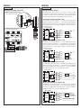
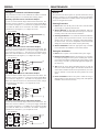
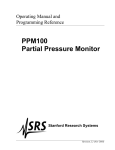
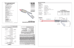
MAD
IN
USA
WARRANTY / DISCLAIMER
OMEGA ENGINEERING, INC. warrants this unit to be free of defects in materials and workmanship for a period of 13 months from date of purchase. OMEGA’s Warranty adds an additional one (1) month grace period
to the normal one (1) year product warranty to cover handling and shipping time. This ensures that
OMEGA’s customers receive maximum coverage on each product.
If the unit malfunctions, it must be returned to the factory for evaluation. OMEGA’s Customer Service
Department will issue an Authorized Return (AR) number immediately upon phone or written request. Upon
examination by OMEGA, if the unit is found to be defective, it will be repaired or replaced at no charge.
OMEGA’s WARRANTY does not apply to defects resulting from any action of the purchaser, including but not
limited to mishandling, improper interfacing, operation outside of design limits, improper repair, or unauthorized modification. This WARRANTY is VOID if the unit shows evidence of having been tampered with or
shows evidence of having been damaged as a result of excessive corrosion; or current, heat, moisture or vibration; improper specification; misapplication; misuse or other operating conditions outside of OMEGA’s control.
Components which wear are not warranted, including but not limited to contact points, fuses, and triacs.
OMEGA is pleased to offer suggestions on the use of its various products. However, OMEGA
neither assumes responsibility for any omissions or errors nor assumes liability for any damages
that result from the use of its products in accordance with information provided by OMEGA,
either verbal or written. OMEGA warrants only that the parts manufactured by it will be as
specified and free of defects. OMEGA MAKES NO OTHER WARRANTIES OR REPRESENTATIONS
OF ANY KIND WHATSOEVER, EXPRESS OR IMPLIED, EXCEPT THAT OF TITLE, AND ALL IMPLIED
WARRANTIES INCLUDING ANY WARRANTY OF MERCHANTABILITY AND FITNESS FOR A
PARTICULAR PURPOSE ARE HEREBY DISCLAIMED. LIMITATION OF LIABILITY: The remedies of
purchaser set forth herein are exclusive, and the total liability of OMEGA with respect to this
order, whether based on contract, warranty, negligence, indemnification, strict liability or
otherwise, shall not exceed the purchase price of the component upon which liability is based. In
no event shall OMEGA be liable for consequential, incidental or special damages.
CONDITIONS: Equipment sold by OMEGA is not intended to be used, nor shall it be used: (1) as a “Basic
Component” under 10 CFR 21 (NRC), used in or with any nuclear installation or activity; or (2) in medical
applications or used on humans. Should any Product(s) be used in or with any nuclear installation or activity,
medical application, used on humans, or misused in any way, OMEGA assumes no responsibility as set forth
in our basic WARRANTY/ DISCLAIMER language, and, additionally, purchaser will indemnify OMEGA and
hold OMEGA harmless from any liability or damage whatsoever arising out of the use of the Product(s) in
such a manner.
RETURN REQUESTS / INQUIRIES
Direct all warranty and repair requests/inquiries to the OMEGA Customer Service Department. BEFORE
RETURNING ANY PRODUCT(S) TO OMEGA, PURCHASER MUST OBTAIN AN AUTHORIZED RETURN (AR)
NUMBER FROM OMEGA’S CUSTOMER SERVICE DEPARTMENT (IN ORDER TO AVOID PROCESSING
DELAYS). The assigned AR number should then be marked on the outside of the return package and on
any correspondence. The purchaser is responsible for shipping charges, freight, insurance and proper packaging
to prevent breakage in transit.
FOR NON-WARRANTY REPAIRS, consult
FOR WARRANTY RETURNS, please have the
OMEGA for current repair charges. Have the folfollowing information available BEFORE contacting
lowing information available BEFORE contacting
OMEGA:
OMEGA:
1. Purchase Order number under which the product
1. Purchase Order number to cover the COST
was PURCHASED,
of the repair,
2. Model and serial number of the product under
2. Model and serial number of the product, and
warranty, and
3. Repair instructions and/or specific problems
3. Repair instructions and/or specific problems
relative to the product.
relative to the product.
omega.com
®
®
OMEGAnet ® On-Line Service
www.omega.com
Internet e-mail
[email protected]
Servicing North America:
Canada:
976 Bergar
Laval (Quebec) H7L 5A1, Canada
Tel: (514) 856-6928
FAX: (514) 856-6886
e-mail: [email protected]
USA: ISO 9001 Certified
One Omega Drive, Box 4047
Stamford CT 06907-0047
Tel: (203) 359-1660
FAX: (203) 359-7700
e-mail: [email protected]
For immediate technical or application assistance:
USA and Canada:
Sales Service: 1-800-826-6342 / 1-800-TC-OMEGA®
Customer Service: 1-800-622-2378 / 1-800-622-BEST ®
Engineering Service: 1-800-872-9436 / 1-800-USA-WHEN®
TELEX: 996404 EASYLINK: 62968934
CABLE: OMEGA
Mexico:
~ol: (001) 203-359-7803
En Espan
FAX: (001) 203-359-7807
e-mail: [email protected]
[email protected]
Servicing Europe:
United Kingdom: ISO 9002 Certified
Frystatska 184/46, 733 01 Karvina´, Czech Republic
Tel: +420 (0)59 6311899
FAX: +420 (0)59 6311114
Toll Free: 0800-1-66342
e-mail: [email protected]
Daimlerstrasse 26, D-75392
Deckenpfronn, Germany
Tel: +49 (0)7056 9398-0
FAX: +49 (0)7056 9398-29
Toll Free in Germany: 0800 639 7678
e-mail: [email protected]
Postbus 8034, 1180 LA Amstelveen
The Netherlands
Tel: +31 (0)20 3472121 FAX: +31 (0)20 6434643
Toll Free in Benelux: 0800 0993344
e-mail: [email protected]
Germany/Austria:
Benelux:
Czech Republic:
One Omega Drive
River Bend Technology Centre
Northbank, Irlam
Manchester M44 5BD
United Kingdom
Tel: +44 (0)161 777 6611
FAX: +44 (0)161 777 6622
France:
11, rue Jacques Cartier
78280 Guyancourt, France
Tel: +33 (0)1 61 37 29 00 FAX: +33 (0)1 30 57 54 27
Toll Free in France: 0800 466 342
e-mail: [email protected]
Toll Free in United Kingdom:
0800-488-488
e-mail: [email protected]
It is the policy of OMEGA to comply with all worldwide safety and EMC/EMI regulations that apply. OMEGA
is constantly pursuing certification of its products to the European New Approach Directives. OMEGA will
add the CE mark to every appropriate device upon certification.
The information contained in this document is believed to be correct, but OMEGA Engineering, Inc. accepts no liability for any errors it
contains, and reserves the right to alter specifications without notice.
WARNING: These products are not designed for use in, and should not be used for, human applications.
Metering & Control Instrumentation
Refractometers
Pumps & Tubing
Air, Soil & Water Monitors
Industrial Water & Wastewater Treatment
pH, Conductivity & Dissolved Oxygen Instruments
OMEGA’s policy is to make running changes, not model changes, whenever an improvement is possible.
This affords our customers the latest in technology and engineering.
OMEGA is a registered trademark of OMEGA ENGINEERING, INC.
© Copyright 2003 OMEGA ENGINEERING, INC. All rights reserved. This document may not be copied, photocopied, reproduced, translated, or reduced to any electronic medium or machine-readable form, in whole or in part,
without the prior written consent of OMEGA ENGINEERING, INC.
䡺
⻬
䡺
⻬
䡺
⻬
䡺
⻬
䡺
⻬
䡺
⻬
M-3949/0403
Powered Level Switch
ENVIRONMENTAL
MONITORING AND CONTROL
䡺
⻬
䡺
⻬
䡺
⻬
䡺
⻬
䡺
⻬
LTU-101, LVU-150, LVC-152
LVC-100 & LVF-210 Series
Heating Cable
Cartridge & Strip Heaters
Immersion & Band Heaters
Flexible Heaters
Laboratory Heaters
NRTL/C
HEATERS
䡺
⻬
䡺
⻬
䡺
⻬
䡺
⻬
䡺
⻬
Data Acquisition & Engineering Software
Communications-Based Acquisition Systems
Plug-in Cards for Apple, IBM & Compatibles
Datalogging Systems
Recorders, Printers & Plotters
DATA ACQUISITION
䡺
⻬
䡺
⻬
䡺
⻬
䡺
⻬
IP
68
pH Electrodes, Testers & Accessories
Benchtop/Laboratory Meters
Controllers, Calibrators, Simulators & Pumps
Industrial pH & Conductivity Equipment
pH/CONDUCTIVITY
䡺
⻬
䡺
⻬
䡺
⻬
䡺
⻬
http://www.omega.com
e-mail: [email protected]
Rotameters, Gas Mass Flowmeters & Flow Computers
Air Velocity Indicators
Turbine/Paddlewheel Systems
Totalizers & Batch Controllers
FLOW/LEVEL
䡺
⻬
䡺
⻬
䡺
⻬
䡺
⻬
“
Transducers & Strain Gauges
Load Cells & Pressure Gauges
Displacement Transducers
Instrumentation & Accessories
PRESSURE, STRAIN AND FORCE
䡺
⻬ Thermocouple, RTD & Thermistor Probes,
Connectors, Panels & Assemblies
䡺
⻬ Wire: Thermocouple, RTD & Thermistor
䡺
⻬ Calibrators & Ice Point References
䡺
⻬ Recorders, Controllers & Process Monitors
䡺
⻬ Infrared Pyrometers
TEMPERATURE
Where Do I Find Everything I Need for
Process Measurement and Control?
OMEGA…Of Course!
User’s Guide
SPECIFICATIONS
Step One
Contact output:
Process temp.:
Pressure:
Sensor rating:
Cable type:
Cable length:
Process mount:
Mount. gasket:
Classification:
CE compliance:
Universal
± 1 mm in water
± 0.5 mm in water
12-36 VDC
25 mA maximum
(1) SPST relay
GP: 120 VAC/VDC @ 1A
(CE: 60 VAC/VDC @ 1A)
Selectable NO/NC
F: -40˚ to 194˚
C: -40˚ to 90˚
150 psi (10 bar) @ 25˚
C., derated @ 1.667
psi (.113 bar) per ˚C.
above 25˚ C.
NEMA 6 (IP68)
4-conductor, #22 AWG
(shielded)
Standard: 10' (3m)
3/4" NPT (3/4" G / Rp)
Viton® (G version only)
General purpose
EN 50082-2 immunity
EN 55011 emission
EN 61010-1 safety
Sensor material: PP-Ryton® (glass fill)
Cable jacket mat.: PP
LVU-150 series Specifications:
Sensor material: -150/-152: PP
-151/-153: PFA
Cable jacket mat.: -150/-152: PP
-151/-153: PFA
Operating Pressure (psi)
Orientation:
Accuracy:
Repeatability:
Supply voltage:
Consumption:
Contact type:
Contact rating:
Pressure / Temperature Derating
LTU-101 series Specifications:
160
Unacceptable
140
Range
120
100
80
Acceptable
60
Range
40
20
00
-40
-20
00
LVC-100 series Specifications:
Dielectric range: > 20 constants
Conductive range: > 100 micromhos
Sensor material: -101/-103: PP
-102/-104: PFA
Cable jacket mat.: -101/-103: PP
-102/-104: PFA
LVC-152 series Specifications:
Dielectric range:
Conductive range:
Sensor material:
Cable jacket mat.:
> 20 constants
> 100 micromhos
PP
PP
20
40
60
80
100
Temperature (¡C)
Ambient Sensor Temperature (¡C)
Common Specifications:
Maximum Tem. / Voltage Derating
Continuous 20 mA Sinking Curve
100
Unacceptable
80
Range
60
40
Acceptable
Range
20
00
-20
12
16
20
24
28
32
36
Operating Voltage (VDC)
LVF-210 series Specifications:
4-20 mA Sensor
Max. Series Resistance (Ohms)
Sensor material: -210/-212: PP
-211/-213: PFA
Cable jacket mat.: -210/-212: PP
-211/-213: PFA
Electrical Loading Limits
1,600
1,400
1,200
1,000
Unacceptable
Range
800
600
Acceptable
400
Range
200
0
12
18
24
30
36
Supply Voltage (VDC)
Table of Common Dielectric Constants
NOTE: Liquids with a dielectric constant less than 20 will not be detected by an LVC-152 series or LVC-100 series level switch, as
factory calibrated.
Acetone
21
Acetoaldehyde
22.2
Acetyl methyl hexyl
ketone
28
Alcohol
16 to 31
Ammonia
15 to 25
Acetic acid
4.1 to 6.2
Butyl chloride
9.6
Barium chloride 9 to 11
Benzene
2.3
Benzine
2.3
Barium nitrate
5.6
Bromine
3.1
Chlorobenzene 4.7 to 6
Chlorotoluene
4.7
Chloroform 4.5 to 5.0
Chlorine, liquid
2.0
Carbon tetrachloride 2.2
Cyan
2.6
Cyclohexane methanol
3.7
D.I. Water
20
Ethyl toluene
2.2
Ethyl alcohol
23
Ethylene glycol
37
Ethylene oxide
14
Ethylene dichloride
11 to 17
Ethylene chloride 10.5
Ethyl acetate
6.4
Ethyl salicylate
8.6
Ethyl stearate
2.9
Ethyl silicote
4.1
Formic acid
59
Ferric oleate
2.6
Freon
2.2
Glycerine
47
Glycol
30
Glycol nitrite
27
Gasoline
2 to 2.2
Hydrochloric acid 4.6
Isobutyric acid
2.7
Isobutyl methyl ketone
13
Jet fuel
1.7
Lead carbonate
18
Lead nitrate
38
Methyl salicylate
9.0
Methanol
33
Methyl alcohol 33 to 38
Margarine, liquid
2.8 to 3.2
Methyl acetate
7.3
N-butyl formate
2.4
Nitrobenzene 26 to 35
Nitrotoluene
25
Naphthalene 2.3 to 2.5
Oils, vegetable2.5 to 3.5
Oils, mineral 2.3 to 2.4
Oils, petroleum
1.8 to 2.2
Oleic acid
2.5
Propane, liquid
1.8 to 1.9
Potassium nitrate
5.0 to 5.9
Potassium chloride 5.0
Stearic acid
2.3
Toluene
2.4
Trichloroethylene
3.4
Trichloroacetic acid 4.5
Terephthalic acid
1.5 to 1.7
Thinner
3.7
Urea
3.5
Vinyl chloride 2.8 to 6
Vinyl alcohol 1.8 to 2.0
Water, 20°C
80
Water, 100°C
48
DIMENSIONS
Step Two
Vibration Level Switch, LTU-101 series
0.7"
3/4" NPT (3/4" G)
10’ Cable (3m)
(18mm)
3/4" NPT (3/4" Rp)
2.3" (57mm)
3.0" (76mm)
4.7" (120mm)
Ultrasonic Level Switch, LVU-150 series
3/4" NPT (3/4" G)
10’ Cable (3m)
3/4" NPT (3/4" Rp)
0.7"
(19mm)
0.7"
3/4" NPT (3/4" Rp)
(19mm)
3/4" NPT (3/4" Rp)
10’ Cable (3m)
2.1" (54mm)
2.8" (71mm)
0.7"
(19mm)
1.3" (32mm)
4.5" (114mm)
3.0" (76mm)
SuperGuard RF Capacitance Level Switch, LVC-152 series
10’ Cable (3m)
(19mm)
3/4" NPT (3/4" G)
0.7"
3/4" NPT (3/4" Rp)
2.6" (67mm)
3.3" (83mm)
5.0" (127mm)
Intrusive RF Capacitance Level Switch, LVC-100 series
3/4" NPT (3/4" G)
10’ Cable (3m)
3/4" NPT (3/4" Rp)
0.7"
(19mm)
0.7"
3/4" NPT (3/4" Rp)
(19mm)
3/4" NPT (3/4" Rp)
10’ Cable (3m)
2.1" (54mm)
2.8" (70mm)
0.7"
(19mm)
1.3" (32mm)
4.5" (114mm)
3.0" (76mm)
Optic Leak Detection Switch, LVF-210 series
3/4" NPT (3/4" Rp)
3/4" NPT (3/4" G)
3/4" NPT (3/4" Rp)
10’ Cable (3m)
2.1" (54mm)
2.8" (71mm)
4.5" (114mm)
* all dimensions are Nominal
0.7"
0.7"
(19mm)
(19mm)
3/4" NPT (3/4" Rp)
10’ Cable (3m)
0.7"
(19mm)
1.3" (32mm)
3.0" (76mm)
SAFETY PRECAUTIONS
Step Three
INTRODUCTION
Step Four
About this Manual:
Vibration Switch:
PLEASE READ THE ENTIRE MANUAL PRIOR TO
INSTALLING OR USING THIS PRODUCT. This manual
includes information on all models of Omega’s powered level
switches: LTU-101 series, LVU-150 series, LVC-152 series, LVC100 series and LVF-210 series. Please refer to the part number
located on the switch label to verify the exact model which you
have purchased.
The Tuning Fork vibration switch operates at a nominal frequency of
400 Hz. As the switch becomes immersed in a liquid or slurry, a corresponding frequency shift occurs. When the measured frequency
shift reaches the set point value, the switch changes state indicating
the presence of a liquid or slurry medium.
User’s Responsibility for Safety:
Omega manufactures a wide range of liquid level sensors and technologies. While each of these sensors is designed to operate in a
wide variety of applications, it is the user’s responsibility to select
a sensor model that is appropriate for the application, install it
properly, perform tests of the installed system, and maintain all
components. The failure to do so could result in property damage
or serious injury.
Proper Installation and Handling:
Because this is an electrically operated device, only properlytrained staff should install and/or repair this product. Use a proper
sealant with all installations. Never overtighten the sensor within
the fitting, beyond a maximum of 80 inch-pounds torque. Always
check for leaks prior to system start-up.
Material Compatibility:
The LVU-150, LVC-100 and LVF-210 series sensors are available
in two different wetted materials. Models LVU-150/-152, LVC101/-103 and LVF-210/-212 are made of Polypropylene(PP).
Models LVU-151/-153, LVC-102/-104 and LVF-211/-213 are
made of Perfluoroalkoxy(PFA), also known by the trade name
Teflon. The LTU-101 series is made of PP with the forks made of
Ryton (40% glass filled) and the LVC-152 series is made of PP.
Make sure that the model you have selected is compatible with the
application liquid. To determine the chemical compatibility
between the sensor and its application liquids, refer to an industry
reference.
Wiring and Electrical:
The supply voltage used to power the sensor should never exceed
a maximum of 36 volts DC. Electrical wiring of the sensor should
be performed in accordance with all applicable national, state, and
local codes.
Flammable, Explosive and Hazardous Applications:
DO NOT USE THE LTU-101, LVU-150, LVC-152, LVC-100 OR
LVF-210 SERIES GENERAL PURPOSE SWITCH IN HAZARDOUS LOCATIONS.
WARNING
The rating for the relay is 120 VAC/60 VDC @ 1A. For CE
rated applications, the relay rating is 60 VAC/60 VDC @ 1A.
Omega’s powered level switches are not recommended for use
with electrically charged application liquids. For most reliable
operation, the liquid being measured may need to be electrically grounded.
Do not squeeze the forks together. Doing so could damage or
break the sensor and void the warranty.
When powering up the LTU-101 series, the start-up procedure
requires the switch to cycle through a wet condition for 1/2 second in
order to determine an initial resonance.
Ultrasonic Switch:
The Ultrasonic level switch generates a 1.5 MHz ultrasonic wave
from a miniature piezoelectric transducer located on one side of the
gap in its sensing tip. Another piezo transducer located on the other
side of the gap acts as a microphone, picking up the sound. When liquid enters the gap in the sensing tip, the audio level changes.
The sensor should be installed so that the liquid will drip out of
the gap when the sensor becomes dry.
Optic Switch:
The Optic Leak Detector use principles of optical refraction to detect
the presence or absence of fluid. A pulsed infrared light beam is internally generated by a light emitting diode and aimed at the slanted
optical tip of the sensor. If the tip is dry, the light beam bounces at a
90 degree angle to a receiving photo transistor, indicating a dry condition. If the tip is immersed in liquid, the light beam will refract out
into the liquid instead of being reflected to the photo transistor, indicating a wet condition.
The Optic Leak Detector can not detect the presence or
absence of specular application liquids that reflect light (such
as milk), or viscous liquids (such as paint) that form a coating
on the sensor tip.
SuperGuard Capacitance Switch:
The SuperGuard level switch generates a pulse-wave radio frequency
signal from the capacitance electrode located in the sensing tip of
each sensor. When liquid comes into contact with the sensing tip, the
capacitance as measured by the sensor changes based on the dielectric constant of the liquid. The guard circuit rejects the negative
effects of coating buildup on the probe by eliminating the coating signal path between the active and reference electrodes.
Intrusive RF Capacitance Switch:
The Intrusive RF Capacitance level switch generates a 300 kHz pulsewave radio frequency signal from the capacitance electrode located in
the sensing tip of each sensor. When liquid comes into contact with
the sensing tip, the capacitance as measured by the sensor changes
based on the dielectric constant of the liquid.
The sensor’s operation may vary based on the dielectric properties of various application liquids. The LVC-152 series &
LVC-100 series sensor is factory-calibrated to be used with liquids with a dielectric value between 20 and 80.
Liquids with a dielectric constant less than 20 will not
be detected by an LVC-152 series & LVC-100 series sensor, as factory calibrated.
INSTALLATION
ELECTRICAL
Step Five
Step Six
Through Wall Installation:
Supply Voltage:
The supply voltage to the powered level switch should never exceed
a maximum of 36 VDC. Omega controllers have a built-in 13.5 VDC
power supply which provides power to all of Omega’s electrically
powered sensors. Alternative controllers and power supplies, with a
minimum output of 12 VDC up to a maximum output of 36 VDC,
may also be used with the powered level switch.
Omega’s powered level switches may be installed through the top,
side or bottom of a tank wall. The sensor has male 3/4" NPT threads
on either side of a 15/16" wrench flat. This enables the user to select
the sensor’s mounting orientation, installed outside of the tank in, or
inside of the tank out.
Required Cable Length:
Determine the length of cable required between the powered level
switch and its point of termination. Allow enough slack to ensure the
easy installation, removal and/or maintenance of the sensor. The
cable length may be extended up to a maximum of 1000 feet, using a
well-insulated, 14 to 20 gauge shielded four conductor cable.
Multi-Point Installation:
Omega’s LVM-10 series mounting system is an in-tank fitting which
enables users to install up to four OMEGA sensors of any technology,
to any depth, along the entire length of track. LVM-10 series may be
installed through the top wall of any tank using a standard 2" NPT
tank adapter. If no tank top installation is available, Omega's side
mount bracket, LVM-30, enables LVM-10 series to be installed
directly to the side wall of a tank.
Wire Stripping:
Using a 10 gauge wire stripper, carefully remove the outer layer of
insulation from the last 1-1/4" of the sensor's cable. Unwrap and discard the exposed foil shield from around the signal wires, leaving the
drain wire attached if desired. With a 20 gauge wire stripper, remove
the last 1/4" of the colored insulation from the signal wires.
Signal Outputs (Current sensing):
The standard method used by Omega controllers; this technology uses
only two wires (Red and Black). The sensor draws 5 mA when it is dry,
and 19 mA when wet. NC/NO status must be set by the controller. The
White and Green wires are not used.
Single-Point Installation:
Red
Omega’s LVM-50 series mounting system is an in-tank fitting which
enables users to install one OMEGA sensor, of any technology, to a
specific depth. The Omega sensor may be installed onto the 3/4" NPT
adapter at the end of the LVM-50 series. LVM-50 series may be
installed through the top wall of any tank using a standard 2" NPT
tank adapter. Omega's side mount bracket, model LVM-30, may also
be used if top wall installation is not available.
Junction
Box
2"
Coupling
+
-
Shield
Ground
Black
+
24 VDC
Power Supply
Multimeter
(mA)
Signal Output (Relay switching):
Allows the sensor to switch a small load on or off directly, using an
internal 1A relay (60 VAC/60 VDC). Omega’s powered level switches features 4 wires (red, black, white and green) and a shield wire. The
NO/NC status is set by the polarity of the voltage feeding the red and
black wires. The green wire is the common for the relay and the white
wire is the NO or NC, depending on the polarity of red and black.
Normally Open Wiring:
LVM-50
Red
Series
Black
High Level Sensor
Shield
Ground
White
Green
LVM-10
+
+
24 VDC
Power Supply
Multimeter
(Continuity)
Series
Normally Open Wiring:
Black
Low Level Sensor
Red
Shield
Ground
White
Green
+
+
24 VDC
Power Supply
Multimeter
(Continuity)
WIRING
WIRING
Step Eight
Wiring to a Omega Controller:
Wiring the Relay Output:
LVCN-110 Series Controller
(4 or 20 mA signal output)
The relay output can be wired as a dry contact to a VDC or VAC
power source. Powered level switch does require 12 - 36 VDC power
to operate the sensor and switch the relay. All illustrations below
identify a Dry switch state as the normal position of the relay.
NC
NO
115 VAC
220 VAC
DELAY
LCVN-120/-130/-140 Series Controller
(4 or 20 mA signal output)
P OWER
I N V E R T D E L AY
-- +
INVERT
D E L AY
(-)
Red
C
Black
R
Green* - Not Used
(+)
GND
White - Not Used
AC
Shld - Not Used
AC
P
INVERT +/-
P
IN
T
U
1
Step Seven
Switching a Normally Open DC Load:
The Red wire connects to Positive (+) of the power supply and the
Black wire connects to Negative (-). The LOAD can be attached to
either the Green or White wires. Complete the circuit by either connecting the Green to (+) VDC power or White to (-) VDC power (see
illustration below).
[Dry Condition]
Sensor
(NO)
-- +
R E L AY 1
R E L AY 2
RED
GRN
SHLD
WHT
BLK
[+]
LOAD
OR
LOAD
[-]
L AT C H
INPUT1
INPUT2A
Red
Black
Shld
Not Used - White
Not Used - Green*
ONOFF
INPUT2B
Switching a Normally Closed DC Load:
The Black wire connects to Positive (+) of the power supply and the
Red wire connects to Negative (-). The LOAD can be attached to
either the Green or White wires. Complete the circuit by either connecting the Green to (+) VDC power or White to (-) VDC power (see
illustration below).
[Dry Condition]
Sensor
(NC)
BLK
GRN
SHLD
WHT
RED
[+]
LOAD
OR
LOAD
[-]
Switching a Normally Open AC Load:
The Red wire connects to Positive (+) of the DC power supply and the
Black wire connects to Negative (-). The LOAD can be attached to
the Green wire and the Hot of the VAC power. Connect the White to
the Neutral of the VAC power (see illustration below).
[Dry Condition]
Sensor
(NO)
RED
GRN
SHLD
WHT
BLK
[+]
LOAD
[AC Power]
[-]
Switching a Normally Closed AC Load:
The Black wire connects to Positive (+) of the DC power supply and
the Red wire connects to Negative (-). The LOAD can be attached to
the Green wire and the Hot of the VAC power. Connect the White to
the Neutral of the VAC power (see illustration below).
[Dry Condition]
Sensor
(NC)
BLK
GRN
SHLD
WHT
RED
[+]
LOAD
[AC Power]
[-]
WIRING
MAINTENANCE
Step Nine
Step Ten
Wiring as a P-Channel or N-Channel output:
General:
The powered level switch can be substituted for either a P-Channel
(PNP, sourcing) output or a N-Channel (NPN, sinking) output.
The powered level switch requires no periodic maintenance except
cleaning as required. It is the responsibility of the user to determine
the appropriate maintenance schedule, based on the specific characteristics of the application liquids.
Normally Open DC Load as a P-Channel Output:
To wire as a NO P-Channel output, follow the directions below. The
Red wire connects to Positive (+) of the power supply and the Black
wire connects to Negative (-). The Green wire is jumpered to the Red
wire while the White wire is connected to the LOAD. Jumper the
LOAD back to the Negative (-) to complete the circuit.
[Dry Condition]
Sensor
(NO)
RED
GRN
SHLD
WHT
BLK
[+]
LOAD
[-]
Normally Closed DC Load as a P-Channel Output:
To wire as a NC P-Channel output, follow the directions below. The
Black wire connects to Positive (+) of the power supply and the Red
wire connects to Negative (-). The Green wire is jumpered to the
Black wire while the White wire is connected to the LOAD. Jumper
the LOAD back to the Negative (-) to complete the circuit.
[Dry Condition]
Sensor
(NC)
BLK
GRN
SHLD
WHT
RED
[+]
LOAD
[-]
Normally Open DC Load as a N-Channel Output:
To wire as a NO N-Channel output, follow the directions below. The
Red wire connects to Positive (+) of the power supply and the Black
wire connects to Negative (-). The White wire is jumpered to the
Black wire while the Green wire is connected to the LOAD. Jumper
the LOAD back to the Positive (+) to complete the circuit.
[Dry Condition]
Sensor
(NO)
RED
GRN
SHLD
WHT
BLK
[+]
LOAD
[-]
Normally Closed DC Load as a N-Channel Output:
To wire as a NC N-Channel output, follow the directions below. The
Black wire connects to Positive (+) of the power supply and the Red
wire connects to Negative (-). The White wire is jumpered to the Red
wire while the White wire is connected to the LOAD. Jumper the
LOAD back to the Positive (+) to complete the circuit.
[Dry Condition]
Sensor
(NC)
BLK
GRN
SHLD
WHT
RED
[+]
LOAD
[-]
Cleaning Procedure:
1. Power: Make Sure that all power to the sensor, controller and/or
power supply is completely disconnected.
2. Sensor Removal: In all through-wall installations, make sure
that the tank is drained well below the sensor prior to removal.
Carefully, remove the sensor from the installation.
3. Cleaning the Sensor: Use a soft bristle brush and mild detergent, carefully wash the powered level switch. Do not use harsh
abrasives such as steel wool or sandpaper, which might damage
the surface sensor. Do not use incompatible solvents which may
damage the sensor's PP, PFA, PVDF or Ryton plastic body.
4. Sensor Installation: Follow the appropriate steps of installation as outlined in the installation section of this manual.
Testing the installation:
1. Power: Turn on power to the controller and/or power supply.
2. Immersing the switch: Immerse the sensing tip in its application liquid, by filling the tank up to the switches point of actuation. An alternate method of immersing the switch during preliminary testing is to hold a cup filled with application liquid up to
the switch's tip.
3. Test: With the switch being fluctuated between wet and dry
states, the switch indicator light in the controller should turn on
and off. If the controller doesn't have an input indicator, use a voltmeter or ammeter to ensure that the switch produces the correct
signal.
4. Point of actuation: Observe the point at which the rising or
falling fluid level causes the switch to change state, and adjust the
installation of the switch if necessary.