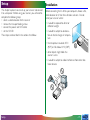
1
Contents
Cautions
Safety Precautions
If You Notice Anything Abnormal
Installation and Storage
Overview
35mm Film Scanner
LS-30
Reference Manual
Parts and Accessories
What’s in the Box
Optional Accessories
System Requirements
Parts of the LS-30
Status LED
Setup
Installation
Connecting the Power Cable
Connecting the SCSI Cable
Setting the SCSI ID
Using the Scanner
Turning the Scanner On
Inserting and Removing Adapters
Using the MA-20 Slide Mount Adapter
Using the SA-20 Strip Film Adapter
Using the IX240 Film Adapter (IA-20)
Turning the Scanner Off
Maintenance
Cleaning
Storage
Transport
-1-
Troubleshooting
Specifications
Contents
-2-
Cautions
• The reproduction of this manual in whole or in part is prohibited save in cases in which Nikon’s prior permission has
been obtained.
• The information contained in this manual is subject to change
without notice.
• Nikon has made every effort to produce a perfect manual,
but should you find any mistakes, we would be grateful if you
would kindly let us know. The address of Nikon’s representative in your area is provided separately.
• We shall take no responsibility for consequences resulting
from the operation of this product, despite the terms mentioned above.
Symbol
The
symbols in this manual signify important safety precautions. All passages marked with this indication should be read
prior to installation to prevent injury to yourself or to others.
These indications are also placed in the table of contents to
mark passages that should be read before use.
✔ Symbol
The ✔ symbols in this manual signify the need for caution when
using the product. These indications are placed in sections that
should be read before operation to prevent damage to the
product.
Trademark Information
Macintosh is a registered trademark of Apple Computer, Inc.
Microsoft and Windows are registered trademarks, and Windows NT a
trademark, of Microsoft Corporation.
IBM PC/AT is a trademark of International Business Machines Corporation.
i386, i486, Pentium, and Pentium II are trademarks of Intel Corporation,
U.S.A.
Adaptec is a registered trademark of Adaptec, Inc.
Adobe and Acrobat are registered trademarks of Adobe Systems, Inc.
The Clean Image function incorporated in the LS-30 makes use of Digital
ICE technology developed by Applied Science Fiction Inc. Digital ICE and
the Digital ICE logo are trademarks of Applied Science Fiction Inc.
Other brand or product names are the trademarks or registered trademarks of their respective holders.
Cautions
-3-
Federal Communications Commission (FCC)
Radio Frequency Interference Statement
CAUTIONS
• Reorient or relocate the receiving antenna.
• Increase the separation between the equipment and receiver.
• Connect the equipment into an outlet on a circuit different
from that to which the receiver is connected.
• Consult the dealer or an experienced radio/television technician for help.
Notice for customers in Canada
Modifications
The FCC requires the user to be notified that any changes or
This equipment has been tested and found to comply with the
limits for a Class B digital device, pursuant to Part 15 of the FCC modifications made to this device that are not expressly apRules. These limits are designed to provide reasonable protec- proved by Nikon Corporation may void the user's authority to
tion against harmful interference in a residential installation. This operate the equipment.
equipment generates, uses, and can radiate radio frequency
SCSI Cable
energy and, if not installed and used in accordance with the
Use the SCSI cable supplied with your scanner (see page 13 of
instructions, may cause harmful interference to radio communi- this manual). Using other interface cables may exceed the limits
cations. However, there is no guarantee that interference will
of the class B Part 15 of FCC rules.
not occur in a particular installation. If this equipment does
Note: A SCSI cable is provided only with scanners sold in the
cause harmful interference to radio or television reception,
which can be determined by turning the equipment off and on, U.S.A. and Canada. In other regions, a ferrite core is provided for
the user is encouraged to try to correct the interference by one attachment to a SCSI cable.
or more of the following measures:
CAUTION
This class B digital apparatus meets all requirements of the
Canadian Interference Causing Equipment Regulations.
ATTENTION
Cet appareil numérique de la classe B respecte toutes les
exigences du Règlement sur le matériel brouilleur du Canada.
Notice for customers in European countries
ACHTUNG
Dieses Gerät entspricht den Bestimmungen der EG-Direktive 87/
308/EEC zur Störungsunterdrückung. Lärmemission kleiner 70 dBA.
Cautions
-4-
Safety Precautions
Observe the following safety precautions when installing and
operating the LS-30:
• Do not allow your fingers, hair, or clothing into the
film insertion slot
Do not insert your fingers, hair, or clothing into the film
insertion slot on the front of the scanner when the power is
on and a film adapter is in place. Doing so could result in
injury.
• Use an appropriate power supply
Use an AC power supply of 50/60Hz and a voltage of from
100V–240V. Be sure to use a power cord rated for the
appropriate voltage.
At voltages of more than AC 125V:
use a power cord that complies with the safety standards of
the country in which it is used, which has a plug rated for AC
250V, 15A (NEMA 6P-15) and insulation of SVT type or
better, and which is more than AWG18 in thickness.
• Connect the scanner to ground
The outlet into which the power cable is plugged must be
grounded. Failure to ground the power supply could result
in electric shock.
* The shape of the cable may
vary depending on the country
of sale.
• The scanner and all devices to which it is connected must be
connected to a common ground. If a common ground is not
used, a ground loop could occur, causing electric shock or
noise static.
• Do not ground the outlet to a gas or water pipe.
At voltages of AC 125V or less:
use a power cord that complies with the safety standards of
the country in which it is used, which has a plug rated for AC
125V, 10A and insulation of SVT type or better, and which is
more than AWG18 in thickness.
Safety Precautions
-5-
• When handling the power and SCSI cables
Unplug the power cable by pulling on the plug, not on the
cable itself. Pulling directly on the cord could result in damage that could cause fire or electric shock.
* The shape of the cable
may vary depending on
the country of sale.
• Do not damage or modify the power or SCSI cables. Fire or
electric shock may result if the cables are placed under heavy
objects, exposed to heat or flame, or forcibly tugged or bent.
• Should the insulation of the cables become damaged and the
wires become exposed, contact your retailer or Nikon
service office for information on repair or replacement.
Continued use could cause fire or electric shock.
• Do not plug the power cord into an extension cord or multipleoutlet extension, as this could result in fire or malfunction.
• When connecting or disconnecting the SCSI cable, handle
the cable by the connector. Do not pull on the cable itself.
ON
OFF
SCSI
6
2
• Do not handle the cables when your hands are wet. Doing
so could cause electric shock.
100098
100098
SS
CC
SS
I I
MADE IN JAPAN
1
3
0
4
5
7
SCSI NB
TERMINATOR
* The shape of the cable may vary
depending on the country of sale.
• Do not connect or disconnect the cables while the power is
on.
Safety Precautions
-6-
• Do not disassemble
The interior of the scanner contains areas of high voltage.
Removing the scanner’s cover could result in fire or electric
shock. Contact your dealer or Nikon service office for
inspection or repair.
• Place on a stable surface
Do not use the equipment on an unstable surface or on a
surface which is not horizontal. This could cause the equipment to fall, resulting in injury.
• Do not modify
Do not modify the equipment. Doing so could cause fire or
electric shock.
• Do not drop
Do not subject the equipment to strong shocks, as this could
cause malfunction or breakage. The scanner contains glass
parts; if the scanner is dropped or otherwise damaged,
caution must be observed to avoid broken glass.
• Do not place heavy objects on the scanner
Safety Precautions
-7-
• Keep clean
Use a dry cloth to remove any dirt from metal sections of
the scanner and their surroundings. Using the equipment
when dirty could cause fire.
• Do not place foreign objects inside the scanner
Do not allow foreign objects of any kind into the unit. If
flammable objects, metal, or water come in contact with the
interior of the scanner, malfunction, fire, or electric shock
could result.
• Do not place vases, flowerpots, cups, cosmetics, vessels
containing chemicals or water, or small metal articles on top
of the equipment. Should such articles or their contents fall
into the equipment, fire, electric shock or malfunction could
result.
• When performing routine maintenance
Before performing maintenance, turn the equipment off and
unplug the power cord.
If You Notice Anything Abnormal
Should you notice an unusual noise, smell, or smoke coming
from the equipment, immediately take the steps detailed below.
• Continued use could cause fire or electric shock. Turn off
the power immediately and then unplug the power cord.
After ensuring that the equipment is no longer smoking,
contact your dealer or Nikon service representative for
information on replacement or repair. DO NOT attempt
repairs yourself, as this would be extremely dangerous.
• Exposing the scanner to volatile substances such as alcohol,
benzine, thinner, or pesticides could cause malfunction, fire,
or electric shock.
• If foreign substances or water should find their way into the
equipment, turn off the power immediately, unplug the
power cord and contact your dealer or nearest Nikon
service office. Continued use could result in fire, electric
shock or malfunction. Particular care is advised in households with small children.
• When not using for an extended period
When not using the equipment for an extended period,
remove any film that may be in the adapters and take the
adapters out of the adapter slot. Turn off the equipment
and unplug the power cord. To prevent accumulation of
dust inside the equipment, close the front cover.
Safety Precautions
-8-
• the scanner would be exposed to direct sunlight
Installation and Storage
To prevent fire or malfunction, follow the precautions given
below when operating or storing the scanner. When not in
use, cover the scanner appropriately to protect it from dust.
Do not store or use where:
• the temperature is above 35°C (95°F) or below 10°C (50°F),
the temperature changes drastically, or condensation occurs
• there is a lot of dust
• the humidity exceeds 80%
Safety Precautions
-9-
• the scanner may be subject to excessive vibration or physical
shock
• the scanner would be exposed to radio interference from
other equipment nearby
• close to other objects that would block the scanner’s vents
Note that the scanner contains glass parts; if the scanner is
dropped or otherwise damaged, caution must be observed to
avoid broken glass.
Safety Precautions
- 10 -
Notice concerning prohibition of copying or
reproduction
Note that simply being in possession of material which has been
copied or reproduced by means of a scanner may be punishable by law.
• Items prohibited by law from being copied or reproduced
• Comply with copyright notices
The copying or reproduction of copyrighted creative works
such as books, music, paintings, woodcut prints, maps, drawings, movies, and photographs is prohibited except when it is
done for personal use at home or for similar restricted and
non-commercial use.
Do not copy or reproduce paper money, coins, securities,
government bonds, or local government bonds, even if such
copies or reproductions are stamped “Sample”.
The copying or reproduction of paper money, coins, or
securities which are circulated in a foreign country is prohibited.
Unless the prior permission of the government has been
obtained, the copying or reproduction of unused postage
stamps or post cards issued by the government is prohibited.
The copying or reproduction of stamps issued by the government and certified documents stipulated by law is prohibited.
• Cautions on certain copies and reproductions
The government has issued cautions on copies or reproductions of securities issued by private companies (shares, bills,
checks, gift certificates, etc.), commuter passes, or coupon
tickets, except when a minimum of necessary copies are to
be provided for business use by a company. Also, do not
copy or reproduce passports issued by the government,
licenses issued by public agencies and private groups, ID
cards, and tickets, such as passes and meal coupons.
- 11 -
Overview
Thank you for your purchase of a Nikon LS-30 scanner for 35
mm and IX240 film. The LS-30 film scanner offers high speed
and high resolution, making it ideally suited to the creation of
high-quality images for desk-top publishing, design, and multimedia production. Removable modular adapters allow scanning
of 35 mm slides and strip film, whether negative or positive,
color or monochrome. An adapter for IX240 film is available
separately. Other features include:
• a bright, four-color LED light source, which eliminates the
need to replace worn-out bulbs
• single-pass, high-speed scanning
• ten-bit analog-to-digital conversion, guaranteeing high image
quality
This reference manual describes the procedures for unpacking,
setting up, and connecting the scanner, and explains how to use
the film adapters available for the LS-30. While the emphasis in
this manual is on setting up and using the scanner, the precautions that should be observed for personal safety and to prevent damage to the equipment are also covered. The next
chapter, “Parts and Accessories,” introduces the parts of the
scanner and the contents of the package. This is followed by
“Setup,” which describes how to connect the power and SCSI
cables and set the SCSI ID. “Using the Scanner” details how to
insert and use the film adapters and how to insert and remove
film and slides. The final sections, “Maintenance” and “Troubleshooting,” give information on caring for your scanner and on
what to do when things go wrong. Please read all instructions
thoroughly to ensure that you get the most from your scanner.
The procedures for using the LS-30 to scan and reproduce
• a maximum of 2,592 x 3,894 pixels and resolutions as high as images are outlined in the User’s Guide. A more detailed expla2,700 dpi
nation of scanning procedures may be found in the software
reference manuals.
• an autofocus function that eliminates the need for manual
focus adjustment
We hope that you will find this manual helpful.
• a compact, lightweight, and energy-efficient design
• random-access and batch scanning, allowing you to preview
and select for scanning any frame or frames in a film strip or
IX240 film cartridge without removing the film from the
scanner
Overview
- 12 -
Parts and Accessories
This chapter introduces the parts of the LS-30 and lists the
items packaged with the scanner or available for purchase
separately. It also lists the requirements for the computer
system that will run the scanner.
What’s in the Box
Purchasers of the LS-30 should find that the package contains all
the items listed below. Should you find that anything is missing
or damaged, contact your retailer immediately.
Power cable (1)
(Shape of cable depends
on country of sale)
FH-2 strip-film
holder for
MA-20 (1)
Fast Track guide (1)
Scanner software CD-ROM for
Windows and Macintosh (1)
MA-20 SLIDE MOUNT
ADAPTER (1)
Reference CD containing
manuals and Adobe Acrobat
Reader (1)
LS-30 main unit (1)
Film tray for SA-20
(1)
SA-20 STRIP FILM ADAPTER
(1)
Parts and Accessories: What’s in the Box
User’s guide (1)
“Open me first”
envelope (1)
Note: Users in the United States
and Canada should also find that
the package contains a SCSI cable
for use with the LS-30. Users in
other regions should find that the
package contains a ferrite core for
attachment to a SCSI cable. You
must use the core or cable provided
if your scanner is to meet interference regulations.
- 13 -
Optional Accessories
System Requirements
At the time of writing, the following optional adapter was
available for the LS-30:
To install and run the driver software for the LS-30, your computer system must meet the requirements listed below.
Macintosh
•
•
•
•
IA-20 adapter for IX240 film
Macintosh or Power Macintosh with a 68030 CPU or better
MacOS System 7.1 or later
ColorSync
a minimum of 16 MB RAM (24 MB or more is recommended)
• 23 MB or more free hard disk space (100 MB or more is
recommended)
• video system supporting a color depth of at least sixteen bits,
or 32,000 colors (a color depth of twenty-four bits, or 16.7
million colors, is recommended)
Windows
• IBM PC/AT or compatible with i486 or better CPU
• Windows 95, Windows NT4.0 or later
• a minimum of 16 MB RAM (24 MB or more is recommended)
• 23 MB or more free hard disk space (100 MB or more is
recommended)
• DOS ASPI-compatible SCSI board with WINASPI.DLL (a list
of boards that have been tested and approved by Nikon is
provided separately)
• video system supporting a color depth of at least sixteen bits,
or 32,000 colors (a color depth of twenty-four bits, or 16.7
million colors, is recommended)
Parts and Accessories: Options
- 14 -
Parts of the LS-30
Adapter
slot
Guard
Transport
locking screw
Sliding
cover
Holders for
locking screws
Transport
locking screw
100–240V~
0.3–0.2A
50/60 Hz
Feet (used
when scanner
is on its side)
AC connector
100098
MADE IN JAPAN
SCSI NB
TERMINATOR
4
1
6 7
2 3
5
Status LED
Feet (used when scanner
is on its base)
0
SCSI
OFF
SCSI
ON
Termination
on/off switch
SCSI ID
selection
switch
Female half-pitch 50-pin
SCSI connectors (2)
Vents
Power
on/off
switch
Parts and Accessories: Parts
- 15 -
Status LED
Note: The LED may sometimes blink erratically, but this does
not indicate a malfunction.
The scanner’s status is shown by the LED on the front panel.
Caution: Do not insert or remove adapters while the LED is
blinking, as this could cause the scanner to malfunction.
✔
Status LED
When the status LED is on and glowing steadily (READY):
the power is on but no operation is being performed.
Adapters can be exchanged and film inserted. If the computer to which the scanner is connected is off, the scanner
can be turned off.
When the status LED blinks slowly (BUSY):
scanning is in progress or the scanner is initializing after
having been turned on. Do not turn the scanner off, remove
or insert adapters, or eject or insert film.
When the status LED flashes rapidly (ERROR):
a communications error has occurred or there is a problem
with the scanner. If this condition persists, close all applications and turn off the computer, then turn off the scanner.
Wait at least five seconds before turning the scanner on
again and restarting the computer.
Parts and Accessories: Status LED
- 16 -
Setup
Installation
This chapter explains how to set up your scanner and connect
it to a computer. Before using your scanner, you will need to
complete the following steps:
• select a suitable location for the scanner
• remove the transport locking screws
• connect the power and SCSI cables
• set the SCSI ID
Before connecting the LS-30 to your computer, choose a flat,
stable location for it, free from vibration and dust. Do not
install your scanner where:
These steps are described in the sections that follow.
• it would be exposed to direct or
reflected sunlight
• it would be subject to condensation or drastic changes in temperature
• the temperature exceeds 35ºC
(95ºF) or falls below 10ºC (50ºF)
• other objects might block the
scanner’s vents
• it would be subject to radio interference from other electronic devices
Setup
- 17 -
The scanner has feet both on its base and on one side, making
When installing the scanner on its side
it possible to place the scanner either on its base or on its side.
When installing the scanner, leave enough space free for ease of
operation. There should be at least 5 cm (2″) of space above
the unit and 10 cm (4″) behind. Space requirements are illustrated below.
When installing the scanner on its base
✔Caution: The scanner must be installed with its feet down,
as shown in the illustrations on this page. Do not store or operate
the scanner in any other orientation.
Setup: Installation
- 18 -
SCSI
OFF
4 5
3
0 1
SCSI NB
6
7
Transport locking screws
Setup: Installation
100098
100–240V~
0.3–0.2A
50/60 Hz
SCSI
MADE IN JAPAN
Coin
Note: Replace the locking screws and guard when transporting
the scanner (see “Maintenance: Transporting the Scanner,”
below).
2
Guard
✔
Caution: Never turn the scanner on with the locking screws
in place. Turning the power on in these circumstances could
damage the scanner.
ON
TERMINATOR
Once the scanner is installed, slide the front cover open. Using
a coin, remove the transport locking screws from the adapter
slot and side panel and screw them into the holes provided on
the rear panel. The adapter slot contains a plastic guard to
prevent the transport screw from falling into the scan mechanism when the transport screw is removed. After removing the
transport screw from the adapter slot and screwing it into one
of the holes on the rear of the scanner, remove the guard and
store it in a safe place.
Holes for locking screws
- 19 -
Connecting the Power Cable
CAUTION !
Before connecting the power cable, confirm that the scanner is • The outlet into which the power cable is plugged must be
grounded. Failure to ground the power supply could result
off and that the transport locking screw has been removed from
in electric shock.
the adapter slot. The scanner is off when the end of the power
switch marked “0” is down.
• The scanner and all devices to which it is connected must be
connected to a common ground. If a common ground is not
used, a ground loop could occur, causing electric shock or
static “noise.”
Power off (“0” end down)
ON
OFF
SCSI
6
2
100098
SCSI
MADE IN JAPAN
1
3
0
4
5
Shape of plug depends
on country of sale
• Use an independent outlet whenever possible. If the scanner
is plugged into an outlet to which a household appliance
such as a vacuum cleaner or air-conditioner is connected, the
scanner’s power supply may be subject to noise.
7
SCSI NB
TERMINATOR
Attach the female end of the power cable to the AC connector
on the rear of the scanner and insert the male end into a general-purpose household outlet (100 V AC, 50/60 Hz).
• Do not plug the power cord into an extension cord or multipleoutlet extension, as this could result in fire or malfunction.
Shape of plug depends
on country of sale
Setup: Connecting the Power Cable
- 20 -
Connecting the SCSI Cable
Communication between your computer and the LS-30 relies
on the Small Computer System Interface, or SCSI, standard.
For connection to the scanner and other SCSI devices, a SCSI
controller must be installed in your computer. While Macintosh
computers come with a SCSI controller built-in, most IBM
PC/AT compatibles require a SCSI controller to be installed in
the form of a SCSI expansion board or PCMCIA card. Nikon
recommends Adaptec SCSI adapters with the 32-bit version of
WINASPI.DLL for computers running Windows 95 or Windows NT 4.0 (a list of adapters that have been tested and
approved by Nikon is provided separately).
To install a SCSI adapter in a computer running Windows 95 or
Windows NT 4.0, follow the instructions provided by the
manufacturer. In the case of expansion boards and some
PCMCIA cards, it is necessary to turn the computer off and
disconnect the power cable and all peripheral devices before
beginning installation. When the computer is powered on after
installation, the Windows Hardware Wizard should detect the
SCSI adapter and, if necessary, prompt you to install driver
software for the device. Once installation is complete, check to
be sure that the system resources used by the adapter do not
conflict with those used by other devices. If any conflicts are
found, resolve them as instructed in the manufacturer’s manual.
✔Caution: Do not attempt to connect the scanner to your
computer until a SCSI adapter has been installed and any resource
conflicts resolved.
Setup: Connecting the SCSI Cable
After installing a SCSI adapter on a computer running Windows 95, check for
resource conflicts.
1. Click the My Computer icon with the
right mouse button and select Properties
from the menu that appears. The
System Properties window will be
displayed. Open the Device Manager tab.
SCSI controller
2. If the card has been installed correctly, the System Properties window
will contain a “SCSI controllers” icon. If “?” “!” or “✘” is showing
next to the name of the SCSI adapter, there is a problem which must
be resolved before the scanner can be connected. To determine the
cause of the problem, select the adapter icon and click the Properties button to view the drivers and system resources for the device.
- 21 -
SCSI devices are connected to the computer in a “daisy chain.”
Up to eight devices, including the computer and any internal
SCSI devices such as hard drives and CD-ROM drives, can be
connected in a SCSI chain. The first and last devices in the
chain must be terminated, i.e., fitted with special circuitry to
reduce noise, making the connection more reliable. If the LS-30
is the last device in the chain, it can be terminated using the
termination switch on the rear of the scanner. Except in the
case of some laptop computers requiring external terminators,
the other end of the chain will be terminated inside the computer, either at the SCSI adapter or at an internal drive. In the
case of IBM PC/AT computers with internal SCSI devices, it may
be necessary to remove termination from the SCSI adapter
board before connecting external devices.
To connect the scanner to the SCSI chain, a SCSI cable with a
male half-pitch 50-pin connector is required. The other end of
the cable must match the connector on the devices to which
the scanner is to be connected. For direct connection to most
Macintosh computers, a 25-pin D-sub connector will be required (Macintosh laptop computers use a different type of
connector). SCSI boards for IBM PC/AT computers will usually
be provided with a 25-pin D-sub connector, a 50-pin Centronics
connector, or a half-pitch 50-pin connector with the pins arranged in two separate rows or attached to a central “finger.” If
the correct type of cable is not available, an adapter can be
attached to one or both ends of the cable. To prevent interference, SCSI cabling should be of a high-impedance type and be
as short as possible. The total length of cabling in a SCSI chain
must not exceed six meters (twenty feet), but be aware that
the reliability of the SCSI interface will drop as the length of the
cable increases.
Setup: Connecting the SCSI Cable
A SCSI cable is provided with scanners sold in the United States
and Canada. If your scanner was purchased in another region,
before connecting the SCSI cable you should attach the ferrite
core provided with your scanner (the cable provided to customers in the United States and Canada does not require a
core). Place the SCSI cable in the center of the open core and
close the core tightly. The core should be attached as far as
possible from the scanner; i.e., as close as possible to the other
device to which the cable is attached. Attach the plastic tie on
the scanner side of the core to prevent the core from sliding
out of position.
2. Place tie around
cable and pull tight
To LS-30➜
1. Close and latch core
- 22 -
SCSI devices cannot be connected while the power is on.
Before connecting the scanner to the SCSI chain, be sure that
the computer and all other devices in the chain, including the
scanner, are off. How the scanner should be connected to the
chain depends on whether it is to be located between other
devices or attached at the end of the chain.
Connect the other end of the cable to the next device in the
chain. If the scanner is the only external device in the chain,
connect the cable to the computer’s SCSI port.
100–240V~
0.3–0.2A
50/60 Hz
When the scanner is the last device in the chain
100098
MADE IN JAPAN
SCSI NB
TERMINATOR
4
1
6 7
2 3
5
Set the terminator switch on the rear of the scanner to ON.
0
SCSI
OFF
ON
SCSI
TERMINATOR
If there are other external devices in the chain, connect the
scanner to the last of these devices.
Connect the SCSI cable to either of the two SCSI connectors
on the rear of the scanner.
ON
TERMINATOR
OFF
MADE IN JAPAN
2 3
6
4
2
100098
SCSI
MADE IN JAPAN
1
3
TERMINATOR
4
SCSI
connector pins with your fingers or with
metal objects, as this could result in
static electricity damaging one or more
of the devices in the SCSI chain.
Setup: Connecting the SCSI Cable
SCSI NB
6 7
SCSI
100098
0
SCSI NB
Other SCSI device
7
5
Other SCSI device
5
✔Caution: Do not touch the
100–240V~
0.3–0.2A
50/60 Hz
1
ON
- 23 -
0
OFF
OFF
SCSI
ON
When the scanner is between other devices
Set the terminator switch on the rear of the scanner to OFF.
Connect a second SCSI cable to the other of the two connectors on the rear of the scanner, then connect the other end of
the cable to another SCSI device. Confirm that the last device
in the chain is terminated.
TERMINATOR
100–240V~
0.3–0.2A
50/60 Hz
OFF
ON
100098
MADE IN JAPAN
TERMINATOR
1
6 7
2 3
5
ON
Terminator
Note: If the last device in the chain has an unused SCSI connector, a separate terminator should be attached to it, even if the
device is connected to the SCSI chain using a through terminator.
OFF
SCSI
ON
TERMINATOR
OFF
SCSI
6
2
100098
SCSI
MADE IN JAPAN
1
3
0
4
5
7
SCSI NB
0
Connect one end of the SCSI cable to either of the connectors
on the rear of the scanner, then connect the other end to one
of the devices in the chain.
Other SCSI device
SCSI NB
4
SCSI
✔Caution: Do not touch the connector pins with your fingers
or with metal objects, as this could result in static electricity damaging one or more of the devices in the SCSI chain.
Setup: Connecting the SCSI Cable
- 24 -
• When using a SCSI extension board with an IBM PC/AT
compatible computer, be sure that you have the latest
available driver software for your board. If you experience
trouble with SCSI connections, contact the manufacturer to
learn whether an updated driver has been released.
4
6 7
• The total length of cabling in the SCSI chain should be no
more than six meters (twenty feet). The longer the cabling,
the less reliable the connection.
SCSI ID
5
• The maximum number of SCSI devices that can be connected in a single chain is eight, including the computer and
any internal SCSI devices such as hard disks or CD-ROM
drives.
The scanner’s SCSI ID is indicated by the SCSI ID dial on the
rear panel. Before the scanner leaves the factory, the ID is set
to “2.”
2 3
• Be sure that the devices at both ends of the SCSI chain are
terminated. If the host computer is a Macintosh, the chain
will already be terminated at the computer end. In the case
of IBM PC/AT compatibles in a chain which contains external
devices only, the chain should be terminated at the SCSI
board. In the case of a chain which includes internal devices,
you may need to remove termination from the board and
terminate the last internal device.
Each device in the SCSI chain has a unique ID, which is a number between zero and seven that the computer uses to distinguish between different devices. When connecting the LS-30
to a SCSI chain, the scanner’s SCSI ID must be set to a number
that is not shared by any of the other devices, including the
computer itself.
1
• Turn off the computer, the LS-30, and all SCSI devices
before connecting the scanner.
Setting the SCSI ID
0
✔SCSI Connection Checklist
When choosing another ID for the scanner, bear in mind that
the computer will usually have an ID of either “0” or “7,” and
that internal hard disks often have IDs of “0” or “1.” In the case
of Macintosh computers, the computer will have an ID of “7,”
while the internal hard disk and CD-ROM drive often have IDs
of “0” and “3,” respectively. In general, it is recommended that
you set the scanner’s ID to any number other than zero, one,
three, and seven that is not used by another SCSI device.
✔Caution: Assigning the same ID to two different devices
could render the computer system inoperable or result in important
data on a hard disk being lost or corrupted.
Setup: Connecting the SCSI Cable
- 25 -
OFF
SCSI
ON
Note: The LS-30 conforms to Level 1 of the SCAM (SCSI Configuration Auto-Magically) SCSI-selection standard, which allows
some computers to set the scanner’s ID automatically. If your
computer’s operating system supports Plug&Play and the SCSI host
(computer or SCSI extension board) conforms to SCAM, the scanner may be automatically assigned an ID which differs from that
set using the SCSI ID dial. SCAM will not assign conflicting IDs to
SCSI devices.
6
2
100098
SCSI
MADE IN JAPAN
1
3
0
4
5
7
SCSI NB
TERMINATOR
To change the scanner’s ID, turn the scanner off. Then, using a
screwdriver, turn the dial on the back of the scanner to choose
a new ID.
Setup: Setting the SCSI ID
- 26 -
Using the Scanner
Inserting and Removing Adapters
This chapter covers basic scanner operations, from turning the
scanner on to replacing adapters and inserting and removing
film. Actual scanning is outlined in the User’s Guide and described in more detail in the software reference manuals.
The LS-30 uses a variety of adapters to scan different types of
film. Adapters are provided for scanning single 35 mm slide
mounts and 35 mm film in strips of from two to six frames. An
adapter for scanning IX240 film is available for separate purchase.
Turning the Scanner On
Before turning on your computer, turn on the scanner and any
other peripheral devices. The scanner is on when the end of
the power switch labeled “1” is down.
Any of these adapters can be mounted on the scanner while
the scanner is on and connected to a computer. To mount an
adapter, check that the status LED is glowing steadily. Adapters
can not be inserted or removed while the status LED is blinking.
Open the scanner’s front cover and slide the adapter in as
shown below, stopping when the adapter is firmly in place.
Power switch on (“1” down)
When the scanner is turned on, the status LED will blink while
the scanner initializes. Initialization is complete when the LED
glows steadily. Once initialization has completed, turn on any
other peripheral devices and then start the computer.
Using the Scanner: Turning the Scanner On
(The illustration above shows the slide adapter. The direction
of insertion for other adapters is shown below.)
- 27 -
✔Cautions
• Wait until the status LED glows steadily or the scanner is off
before inserting or removing adapters. Do not replace
adapters while the scanner is operating.
• If an adapter does not slide in smoothly, remove it from the
adapter slot and try again. Do not use force.
Using the MA-20 SLIDE MOUNT ADAPTER
When scanning 35 mm slides, insert the slide adapter into the
scanner, stopping when the adapter is firmly in place. The
adapter should be oriented relative to the scanner as shown in
the illustration below.
Inserting slides
Film has an emulsion surface and a base; when examined under
a light, the emulsion side is dull and the base shiny. Viewed
from the base side, the image appears exactly as it would in a
printed photograph. When the photograph is seen from the
emulsion side, left and right are reversed, creating a mirror
image of what would appear in a print.
Using the Scanner: Inserting and Removing Adapters
- 28 -
When the scanner is installed on its side, insert the slides with
the base up and the short side of the aperture facing the scanner. Insert the slide smoothly into the scanner, stopping when it
contacts the back of the slot.
The correct orientations for inserting landscape and portrait
slides are shown below. If the slides are inserted with the top
and bottom of the image reversed, this can be corrected after
scanning using the software provided with your scanner.
Portrait (tall) slide
If the scanner is installed on its base, the shiny surface of the film
should face to the left and the emulsion surface to the right.
Using the Scanner: Using the MA-20 SLIDE MOUNT ADAPTER
- 29 -
Landscape (wide) slide
Do not insert slides with the longer side of the aperture facing
the scanner. The scanner will be unable to scan the edges of
the film.
Note: The best possible results can be achieved only with clean
slides. Before scanning, remove dust from the film with a blower
and wipe the slide gently with a soft, dry cloth to remove fingerprints.
Using the Scanner: Using the MA-20 SLIDE MOUNT ADAPTER
- 30 -
Slides can be removed from the scanner by pressing the eject
button to eject the slide from the adapter and then pulling the
slide the rest of the way out with your fingers.
✔Cautions
• Do not attempt to insert or eject slides while scanning is in
progress.
• Do not move the scanner or subject it to shock or vibration
while scanning is in progress.
• Slides must be between 1.0 mm and 3.2 mm in thickness.
• If the surface of the mount is rough, you may experience
some resistance when inserting or removing the slide.
• Do not leave slides in the adapter for extended periods.
Using the Scanner: Using the MA-20 SLIDE MOUNT ADAPTER
- 31 -
Using the FH-2 to scan strip-film
Step 2—Place film in the holder
The SA-20 STRIP FILM ADAPTER is provided to scan 35 mm film in
strips of from two to six frames. The SA-20’s automatic feed
and eject mechanisms however require film that is flat, cut
straight across at the ends, free from adhesive tape and has all
perforations intact (see “Using the SA-20 STRIP FILM ADAPTER,”
following). Film that cannot be scanned using the SA-20 can be
scanned in the MA-20 using the FH-2 strip-film holder provided
with your scanner. This section details how to insert film in the
FH-2 and scan it using the MA-20.
Place a strip of 35 mm film on the lower holder, oriented so
that the frame numbers are not reversed. Align each frame in
the film with an aperture in the lower holder.
Aperture
Step 1—Open the FH-2
Holding the FH-2 with the “Nikon” logo facing upwards, unlatch
the holder by the snaps and flip it open.
Film strip
Holder snaps
Lower holder
Using the Scanner: Using the MA-20 SLIDE MOUNT ADAPTER
- 32 -
Step 3—Close the FH-2
Step 5—Insert the FH-2 into the slide adapter
Close the FH-2, keeping the ends of the black lower and upper Insert the FH-2 in the film slot of the MA-20, with the “Nikon”
holders aligned. Fasten the snap on the FH-2 and fit the ends of logo upwards. The direction of insertion depends on which of
the upper and lower holders together.
the frames in the apertures of the metal part of the FH-2 is to
be scanned (in the illustrations below, the arrows show the
direction of insertion).
1
The first
frame will
be scanned
4
The fourth
frame will
be scanned
2
The fifth
frame will
be scanned
5
The third
frame will
be scanned
Step 4—Choose the frame to be scanned
The MA-20 can scan only one frame of film at a time. Slide the
black plastic holder to align frame to be scanned with one of
the two apertures in the metal part of the FH-2.
3
The sixth
frame will
be scanned
Using the Scanner: Using the MA-20 SLIDE MOUNT ADAPTER
The second
frame will
be scanned
6
- 33 -
Slide the film holder into the slide adapter until the holder
touches the back of the film slot. Do not attempt to force the
holder in past the mark.
✔Cautions
• If the holder does not slide smoothly into the adapter film
slot, remove it from the adapter and try again. Do not use
force.
• The film holder is for use with the MA-20 only. Do not
attempt to use the holder with other adapters.
Mark
• Before scanning, remove dust from the film with a blower or
brush.
• Do not use the eject button when removing the holder from
the adapter. Slide the holder out by hand.
When removing the holder from the adapter, wait until the
status LED glows steadily, then slide the holder out by hand.
Do not use the eject button.
Using the Scanner: Using the MA-20 SLIDE MOUNT ADAPTER
- 34 -
Using the SA-20 STRIP FILM ADAPTER
35 mm film-strips of from two to six frames in length can be
scanned using the strip-film adapter. Insert the adapter into the
scanner’s adapter slot as shown below, sliding it in until it contacts the back of the slot. Push the adapter until the connector
on the rear of the adapter is seated securely in the socket at the
back of the slot.
A plastic tray is provided with the strip-film adapter to catch film
ejected from the scanner. If the scanner has been installed on
its side, this tray can be attached to the adapter by inserting the
hooks on the back of the tray into the holes provided on the
bottom of the adapter and then pulling the tray slightly forward.
2. Pull forward to latch
1. Insert hooks
Using the Scanner: Using the SA-20 STRIP FILM ADAPTER
- 35 -
Inserting film
To scan a film strip, grasp the film gently by the sides and slide it
into the adapter’s film slot a short distance. The adapter’s feed
mechanism will be activated and the film will be fed into the
scanner automatically.
As is the case with mounted slides, strip film should be inserted
with the base up and the emulsion surface down. The film is in
the correct orientation if the frame numbers on the film are not
reversed. The film’s edges should be flat or curled slightly
downward. Do not use film which curls upwards or which is
curled more than 3 mm, as the film may jam or fail to scan
properly. Film for use in the scanner should fit in the gauge on
top of the adapter.
< 3 mm
Film will be ejected from the scanner automatically when the
scanner is turned on or when no operation is performed for
several minutes. Film can also be ejected using the software
provided with your scanner. For details of scanning operations,
refer to the User’s Guide or software reference manual.
Using the Scanner: Using the SA-20 STRIP FILM ADAPTER
Note: Due to varying degrees of curl in strip film, autofocusing
may not perform well when scanning the portion of the image
close to the front edge of the first frame. If you experience problems with autofocus, eject the film, turn it around so that the first
frame is now the last, then re-insert the film and scan the last
frame. You can also scan the frame in the MA-20 using the FH-2
strip-film holder (see “Using the MA-20 SLIDE MOUNT ADAPTER,”
above).
- 36 -
✔Cautions
When no film is visible in the film slot
• Do not attempt to insert film while scanning is in progress.
Step 1—Remove the adapter from the scanner
• Do not remove the adapter or turn the scanner off when
there is film in the adapter. Use the driver software provided with your scanner to eject the film.
Wait until the status LED glows steadily, then slide the adapter
from the scanner. If the status LED is flashing rapidly, close all
programs and turn off the computer, then turn off your scanner
and remove the adapter.
• Do not leave film in the adapter for extended periods
• Do not move the scanner while scanning is in progress.
Step 2—Open the adapter
• Examine the film carefully prior to scanning. Film cannot be
used in the adapter if:
• there is tape on the film
• the film has been folded
• the perforations have been torn
• the film has been cut on an angle or torn
Film that cannot be used in the SA-20 can be scanned with
the MA-20 using the FH-2 film holder provided with your
scanner (see “Using the MA-20 SLIDE MOUNT ADAPTER,” above).
With a coin or screwdriver, loosen the screw on top of the
adapter and open the top cover.
2. Open adapter
• Film for use in the SA-20 must be clean and free from fingerprints. If there is dirt on the film, damage to the film could
result. Before scanning, remove dust with a blower and
gently wipe off any finger prints with a soft, dry cloth.
What to do if film jams in the adapter
If film cannot be ejected from the scanner using the software
provided or does not eject automatically after ten minutes have
passed with no operation being performed, you will need to
remove the film from the adapter by hand. The process for
clearing jams is given below.
Note: If the SA-20 jams repeatedly, clean the adapter as described in the following section.
Using the Scanner: Using the SA-20 STRIP FILM ADAPTER
1. Loosen screw
- 37 -
Step 3—Remove the film
The jammed film will be visible in the feed mechanism at the
rear of the adapter. Grasp the film gently by both edges and
pull it slightly upwards, being careful not to damage the film.
Once the end of the film is free, pull the film slowly backwards
out of the adapter with one hand while guiding the free end
with the other, being sure that the film does not catch on the
adapter or other objects. Keep the angle at which film is pulled
from the adapter as low as possible to prevent damage to the
film.
Step 4—Close the adapter
Close the adapter and, with a coin or screwdriver, tighten the
screw on the top of the adapter until the top portion of the
adapter is securely in place.
When film protrudes from the film slot
Step 1—Remove the adapter from the scanner
Wait until the status LED glows steadily, then slide the adapter
Free the end of the film at the rear of the adapter first by pulling from the scanner. If the status LED is flashing rapidly, close all
the film upwards a little at a time. Do not pull on the film that
programs and turn off the computer, then turn off your scanner
remains in the front part of the adapter, as the film could catch
and remove the adapter.
in the mechanism and suffer damage.
Step 2—Pull the film slowly out of the adapter
Grasp the film gently by both edges and pull the film slowly
forward out of the film slot.
Using the Scanner: Using the SA-20 STRIP FILM ADAPTER
- 38 -
Cleaning the strip-film adapter
It is strongly recommended that you clean the SA-20 periodically to prevent dust from damaging the film. If the film to be
scanned is of particular value, it is recommended that you clean
the adapter immediately before use. To clean the adapter,
remove the adapter from the scanner and, with a coin or
screwdriver, loosen the screw on top of the adapter. Open the
adapter and remove all dust with a blower. When you have
finished, close the adapter and, with a coin or screwdriver,
tighten the screw on the top of the adapter until the top portion of the adapter is securely in place.
Using the Scanner: Using the SA-20 STRIP FILM ADAPTER
Using the IX240 Film Adapter (IA-20)
An optional adapter for scanning IX240 film with the LS-30 is
available for separate purchase. To use the IX240 adapter,
insert it into the scanner’s adapter slot as shown below, sliding it
in until it contacts the back of the slot. Push the adapter until
the connector on the rear of the adapter is seated securely in
the socket at the back of the slot.
- 39 -
Insert the film cartridge in the film chamber as shown below.
Inserting film
IX240 film must be developed before it can be scanned. To
determine whether a roll of IX240 film has been developed,
examine the end of the film cartridge where its current status is
marked. If there is a white square showing in the fourth box,
the film has been developed and can be scanned.
Direction of insertion
This way up
To scan IX240 film, press the latch button to open the adapter
cover.
Close the cover, pushing it closed until the latch snaps into
place. The scanner will automatically feed film from the IX240
cartridge into the scanner. For details on scanning IX240 film,
see the software reference manual.
Latch button
Using the Scanner: Using the IX240 Film Adapter
Note: If no operation is performed for several minutes, the film
will automatically be wound back into the canister. Film will be fed
into the scanner once more when the Nikon Scan scan window is
opened or a preview or thumbnail scan is performed.
- 40 -
✔Cautions
Turning the Scanner Off
• The latch button will lock when film is fed from the cartridge
into the scanner. Do not attempt to open the latch until the
film has rewound or been ejected as described in “Removing
Film,” immediately below.
To turn the scanner off, end scanning operations and turn off
the computer. Wait for until the status LED is glowing steadily,
then turn the scanner off.
• Do not remove the adapter with film inside and the cover
closed. Open the cover and remove the film before replacing the adapter.
• Do not insert undeveloped film in the adapter.
• Do not move the scanner while scanning is in progress.
• The number of times IX240 film can be unwound from the
cartridge is limited. When scanning IX240 film, scan as many
images in a session as possible to minimize the number of
times the film is wound and unwound. If you notice an
unusual noise when scanning IX240 film, remove the film as
described below and take it to a developer to have a copy
made. Use the copy when making further scans.
✔Cautions:
• Be sure that the computer is off before turning off the
scanner and other peripherals. Do not turn the scanner off
while the status LED is blinking.
• Once the power is off, wait at least 5 seconds before turning
the scanner on again.
Removing Film
To remove film from the adapter, click the “eject” button ( )
in the Nikon Scan scan window (see the software reference
manual for your platform). Wait until the scanner’s status LED
glows steadily, then open the cover and take the film out with
your fingers.
Using the Scanner: Using the IX240 Film Adapter
- 41 -
Maintenance
Storage
This chapter describes how to clean, store, and transport the
LS-30.
When you do not plan to use the scanner for an extended
period of time, remove any film that may be in the adapters and
take the adapters out of the adapter slot. Turn off the scanner,
unplug it, and disconnect it from the computer. Close the
sliding cover to prevent the accumulation of dust inside the
adapter slot. Store the LS-30 in a dry, well-ventilated environment, away from electronic equipment such as televisions or
radios which produce strong magnetic fields. Do not store the
scanner where the temperature exceeds 60ºC (140ºF) or goes
below -20ºC (-4ºF), or where the relative humidity falls below
20% or exceeds 90%.
Cleaning
Before cleaning the scanner, turn it off and unplug the power
cord. Remove adapters from the scanner before cleaning them.
The exterior of the adapters and the front of the scanner are
made of plastic, and consequently cannot be cleaned with
volatile cleaners such as alcohol or paint thinner. Use a blower
to blow off dust or wipe the surface with a dry cloth. Remove
dirt from the metal rear panel of the scanner using a soft, dry
cloth. If this is not sufficient to remove all dirt, clean with a
cloth that has been slightly dampened with a neutral detergent
or liquid soap.
✔Cautions
• Do not use water or a volatile liquid such as alcohol, benzine,
or thinner. Should any of these liquids come in contact with
the interior of the scanner, fire, electric shock, or malfunction
could result.
• Volatile liquids such as alcohol, benzine, or thinner could
stain the exterior of the scanner and adapters.
Periodically unplug the power and SCSI cables and wipe the
dust off with a damp cloth. Do not allow dust to collect on the
plug, as this could cause fire.
Maintenance: Cleaning
- 42 -
Transport
The LS-30 is for use only in the country of sale. Nikon will not
be held responsible for consequences resulting from use overseas.
Remove the transport locking screws from the rear panel and
screw them into the holes provided in the side panel and the
mouth of the adapter slot (the hole in the mouth of the slot
should align with the hole in the guard). Close the front cover
and pack the scanner and adapters in the original packing material for transport.
The scanning mechanism must be locked in its home position for
transport within the country. To return the scanning mechanism
Caution: Do not transport the scanner without first locking
to its home position, remove any adapters from the adapter
the scanning mechanism with the transport lock screws. Moving
slot and then turn the scanner on. The status LED will blink
the scanner without the lock screws in place could damage the
while the scanning mechanism returns to the home position.
mechanism.
Wait until the status LED glows steadily, then turn off and
unplug the scanner. Place the guard in the adapter slot as
shown below, sliding it in until it contacts the back of the slot.
✔
Maintenance: Transport
- 43 -
Troubleshooting
If you should encounter problems with your scanner, check the
following before contacting your retailer or Nikon representative. If the problems occurred during scanning, you may wish to
refer to the software reference manual for advice on troubleshooting scanning problems.
Problem: the status LED does not light
Checklist
• Is the power switch set to ON?
The scanner is on when the end of the power switch labeled
“1” is down. See the Fast Track Guide or the “Using the
Scanner” section of this manual.
• Is the power cable properly connected at both ends?
After making sure that the scanner and any devices to which
it is connected are switched off, connect the power cable as
described in the Fast Track Guide or the “Setup” section of
this manual.
Problem: the scanner will not scan
Scanning problems are often related to a problem in the SCSI
connection or to improperly installed software. In rare situations,
there may be a problem with the system itself, in which case a
complete reinstall of the operating system may be necessary.
SCSI checklist
Before checking the items listed below, make sure that the
scanner and any devices to which it is connected are off.
• Is the SCSI cable loose or not connected?
Check the SCSI cabling to be sure that the cable is firmly
connected to the connectors.
Troubleshooting
• Are both ends of the SCSI chain terminated?
If the SCSI chain is not properly terminated, you will experience intermittent problems with all SCSI devices. The chain
must be terminated at both ends: if you have a IBM PC/AT
compatible with a SCSI expansion board and no internal
SCSI devices, check that the board is terminated (refer to
the manufacturer’s manual). If you are using an IBM PC/AT
compatible with a SCSI expansion board and internal SCSI
devices, remove termination from the board and terminate
the last internal device in the chain. If the scanner is connected at the end of the chain, set the terminator switch to
ON. If the scanner is connected between other SCSI devices, terminate the last device in the chain and set the
terminator switch on the scanner to OFF. If there is an
unused SCSI connector at the end of the chain, place an
independent terminator on this connector even if the device
is connected to the chain using a through terminator. See
“Setup” in this manual.
• Does the cabling total more than six meters in length?
For a reliable connection, SCSI cabling should be as short as
possible. Use short, high-impedance cables.
• Is the scanner’s ID the same as that of another SCSI device?
Each SCSI device must have a unique ID. Set the scanner’s
ID to a number not used by any other devices in the chain.
Remember that the computer is assigned an ID, usually “0”
or “7,” while internal hard disks often have IDs of “0” or “1.”
In the case of Macintosh computers, the host computer has
an ID of “7” while “0” and “3” may be assigned to an internal hard disk or CD-ROM drive.
- 44 -
Software checklist
• If you are using an IBM PC/AT compatible computer, has
your SCSI board or PCMCIA card been tested and approved • Does your computer system satisfy the requirements given
in “Parts and Accessories” in this manual and in the User’s
by Nikon?
Guide?
A list of Nikon-approved SCSI adapters is provided separately. If your adapter is not on this list, you may need to
• Is the software installed correctly?
purchase and install a Nikon-approved adapter before your
Installation instructions are given in the User’s Guide and the
scanner will work.
software reference manual.
• If you are using an IBM PC/AT compatible computer, do you As a last resort, it may be necessary to reinstall the scanner
have updated drivers for your SCSI adapter?
software. Follow the instructions for de-installation given in the
SCSI drivers are updated as new SCSI devices appear on the software reference manual for your platform, then restart your
market and as incompatibilities are found with existing SCSI
computer and reinstall the software as instructed in the Fast
devices. Check with the board’s manufacturer to determine Track Guide or software reference manual.
whether problems have been discovered with your existing
driver and if so, how to obtain replacement software. If you In the case of IBM PC/AT compatibles, it may be necessary to
are using a Nikon-approved Adaptec SCSI adapter, informa- reinstall the drivers for the SCSI board. To do so, click the My
Computer icon with the right mouse button and select Proption can be obtained on the World-Wide Web at the
erties from the menu that appears. This will open the System
following site: http://www.adaptec.com (note that this URL
Properties window. Click the Device Manager tab and select
may have changed since this manual was written).
your SCSI adapter from under the list of SCSI controllers (if
• If you are using an IBM PC/AT compatible computer, do the your adapter is not listed, check whether there is a SCSI consystem resources used by your board conflict with those
troller listed under “Other Devices” category and if so, select it
allocated to other devices?
instead). Click the Remove button at the bottom of the
Resource conflicts can be identified in Windows 95 by
System Properties window and select OK in the window that
opening the System Properties window and clicking the
appears. If a message appears stating that it is not clear whether
Device Manager tab as described in the “Setup” section of
the device can be removed safely, click Test. Uninstall the
this manual. If there is a conflict, it may be possible to rescanner software as described in the Window’s software refersolve it from the Device Manager, or it may be necessary to ence manual, then power down the computer. After ensuring
set jumpers on the board. Follow the instructions in the
that all SCSI devices, including the scanner, are off, turn on your
computer and start Windows. After installing the driver softmanual for the SCSI adapter.
ware for the SCSI adapter as described in the manufacturer’s
manual, follow the steps given in the Fast Track and user’s
guides to set up your scanner and reinstall the scanner software.
Troubleshooting
- 45 -
Problem: the scan window controls are grayed out or
a “no adapter” or “no media” error appears when
you attempt to scan an image using Nikon Scan
Check that there is an adapter in the device and that it is fully
inserted in the adapter slot. The scanner will not recognize the
SA-20 or optional IA-20 adapter unless the connector on the
rear of the adapter is fully inserted in the connector at the back
of the adapter slot. If the adapter is in place, check that the film
is properly inserted in the adapter.
Problem: the quality of scanned images is poor
Checklist:
• Is there dust on the film?
Remove dust from the film with a blower and scan the
image again.
• Is the film to be scanned properly inserted in the scanner?
Reinsert the film and try again.
• Did you move the film or scanner while scanning was in
progress?
Do not attempt to insert or remove film while scanning is in
progress. Moving the scanner while the status LED is flashing
could cause malfunction. Install the scanner in an environment free of vibration and shocks.
• Are you using the software correctly?
Refer to the User’s Guide and software reference manuals for
details on how to adjust image quality prior to scanning.
Troubleshooting
- 46 -
Specifications
Interface:
SCSI-2 compliant, half-pitch 50-pin connectors (x 2)
LS-30
Dimensions:
85.5 mm (W) x 275.0 mm (D) x 142.0 mm
(H) (3.37″ × 10.83″ × 5.59″)
Weight:
Approx. 2.4 kg (5 lbs 5.7 oz)
Power supply:
100–240 VAC, 0.3–0.2 A, 50/60 Hz
Film:
35 mm film
Positive and negative film, both color and
monochrome, may be used. Film may be
mounted as 35 mm slides (mounts must be
1.0 mm–3.2 mm thick) or strip film of up to
six frames.
IX240 film cartridge (with optional IA-20
adapter for IX240 film)
Scanning system: Fixed-film, movable plane-scanning single-pass
optical system
Operating environment:
Operating temperature
Humidity
+10ºC (50ºF) to +35ºC (95ºF)
20% to 85% (no condensation)
MA-20 SLIDE MOUNT ADAPTER
Sensor:
2592 linear-pixel CCD image sensor
Film:
With FH-2
Light source:
Red, green, and blue (RGB) LEDs
Operating mode: Inserted in LS-30 adapter slot
Color separation: Performed by RGB color LEDs
Aperture size:
35 mm slides, 1.0–3.2 mm thick
35 mm film strips of one to six frames
Same as slide aperture (22.5 mm x 34.3 mm,
2400 x 3658 pixels)
23.4 mm x 35.4 mm, 2496 x 3776 pixels
Valid scanning range:
24.3 mm x 36.5 mm, 2592 x 3894 pixels
FH-2
Rectilinear 11 µm pixels
Dimensions:
70.3 mm (W) × 158.0 mm (D) × 49.0 mm
(H) (2.77″ × 6.22″ × 1.93″)
Weight:
Approx. 100 g (3.6 oz.)
Pixel size:
Optical resolution:
Maximum 2700 pixels/25.4 mm (2700 dpi) at
film surface
Analog-to-digital conversion:
10 bits for each color
Output:
Full color (8 bits for each color)
Focus:
Autofocus
Specifications
- 47 -
SA-20 STRIP FILM ADAPTER
Film:
35 mm film strips of two to six frames (film
must be flat or curl towards the emulsion
surface not more than 3 mm, be free from
adhesive tape, have all perforations intact, and
be cut straight across)
Operating mode: Connected directly to the connector at rear
of scanner adapter slot
Aperture size:
23.4 mm x 35.4 mm, 2497 x 3776 pixels
Dimensions:
68.0 mm (W) × 206.0 mm (D) × 54.5 mm
(H) (2.68″ × 8.11″ × 2.14″)
Weight:
Approx. 200 g (7.1 oz.)
Power supply:
5 VDC, 0.2 A, 15.5 V, 0.7 A or less, supplied
from LS-30
IA-20 IX240 adapter (option)
Film:
Developed IX240 film cartridge
Operating mode: Connected directly to the connector at rear
of scanner adapter slot
Dimensions:
84.0 mm (W) × 207.5 mm (D) × 58.5 mm
(H) (3.31″ × 8.17″ × 3.30″)
Weight:
Approx. 270 g (9.6 oz.)
Power supply:
5 VDC, 1.7 A or less, supplied from LS-30
Specifications
- 48 -
EC DECLARATION OF CONFORMITY
ERKLÄRUNG ÜBER EG-NORMENGERECHTHEIT
We
Name:
Address:
declare that the product
Product Name:
Nikon Film Scanner LS-30, SLIDE MOUNT ADAPTER MA-20, STRIP
FILM ADAPTER SA-20, IX240 Film Adapter IA-20
Manufacturer’s Name:
Nikon Corporation
Manufacturer’s Address:
Fuji Bldg., 2-3, Marunouchi 3-chome, Chiyoda-ku, Tokyo 1008331, Japan
is in conformity with the following Standards
Safety:
EN60950
EMC:
EN55022 Class B
EN61000-3-2 1995
EN61000-3-3 1995
EN50082-1
IEC801-2: 1991 4kV (direct discharge), 8kV (air
discharge)
IEC801-3: 1984 3V/m
IEC801-4: 1988 1kVAC (0.5kV, I/O)
following the provisions of the EMC Directive (89/336/EEC).
Wir
Name:
Nikon Europe BV
Anschrift:
Schipholweg 321, 1171 PL Badhoevedorp, The Netherlands
erklären hiermit, daß das folgende Produkt
Produktbezeichnung:
Nikon Film Scanner LS-30, SLIDE MOUNT ADAPTER MA-20, STRIP
FILM ADAPTER SA-20, IX240 Film Adapter IA-20
Name des Herstellers:
Nikon Corporation
Anschrift des Herstellers:
Fuji Bldg., 2-3, Marunouchi 3-chome, Chiyoda-ku, Tokyo 1008331, Japan
den nachstehend aufgeführten Normen genügt:
Sicherheit:
EN60950
EMC:
EEN55022 Klasse B
EN61000-3-2 1995
EN61000-3-3 1995
EN50082-1
IEC801-2: 1991 4kV (Direkt Entladung), 8kV (Raum
Entladung)
IEC801-3: 1984 3V/m
IEC801-4: 1988 1kVAC (0.5kV, I/O)
und zwar gemäß den Bestimmungen der EMC-Richtlinie (89/336/EEC).
DECLARATION DE CONFORMITÉ DE LA CEE
DECLARACIÓN DE CONFORMIDAD DE LA CEE
Nous
Nom:
Adresse:
déclarons que ce produit
Nom du produit:
Nosotros
Nombre:
Dirección:
declaramos que el producto
Nombre del producto:
Nom du fabricant:
Adresse du fabricant:
est conforme aux normes suivantes
Sécurité:
CEE:
Nikon Europe BV
Schipholweg 321, 1171 PL Badhoevedorp, The Netherlands
Nikon Europe BV
Schipholweg 321, 1171 PL Badhoevedorp, The Netherlands
Nikon Film Scanner LS-30, SLIDE MOUNT ADAPTER MA-20, STRIP
FILM ADAPTER SA-20, IX240 Film Adapter IA-20
Nikon Corporation
Fuji Bldg., 2-3, Marunouchi 3-chome, Chiyoda-ku, Tokyo 1008331, Japon
EN60950
EN55022 Classe B
EN61000-3-2 1995
EN61000-3-3 1995
EN50082-1
IEC801-2: 1991 4kV (décharge par court-circuit), 8kV
(décharge par amorçage)
IEC801-3: 1984 3V/m
IEC801-4: 1988 1kVAC (0.5kV, I/O)
selon les dispositions de la directive de la CEE (89/336/EEC).
Nombre del fabricante:
Dirección del fabricante:
Nikon Europe BV
Schipholweg 321, 1171 PL Badhoevedorp, The Netherlands
Nikon Film Scanner LS-30, SLIDE MOUNT ADAPTER MA-20, STRIP
FILM ADAPTER SA-20, IX240 Film Adapter IA-20
Nikon Corporation
Fuji Bldg., 2-3, Marunouchi 3-chome, Chiyoda-ku, Tokyo 1008331, Japón
cumple las normas siguientes:
Seguridad:
EMC:
EN60950
EN55022 Clase B
EN61000-3-2 1995
EN61000-3-3 1995
EN50082-1
IEC801-2: 1991 4kV (descarga directa), 8kV (descarga
ambiental)
IEC801-3: 1984 3V/m
IEC801-4: 1988 1kVAC (0.5kV, I/O)
según las disposiciones de la Directiva EMC (89/336/EEC).
Badhoevedorp, The Netherlands
Place
Lieu
Ort
Lugar
July 12th, 1998
Date
Date
Datum
Fecha
Signature/Managing Director
Signature/Directeur général
Unterschrift/Geschäftsführer
Firma/Director general
- 49 -