1
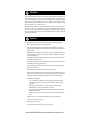
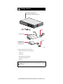
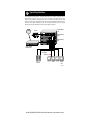
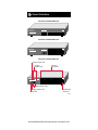
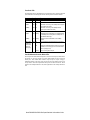
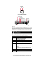
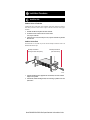
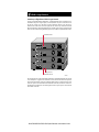
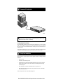
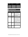
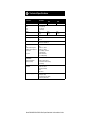
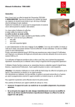
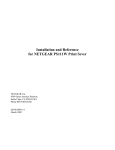
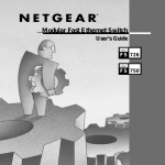
Start Here
The NETGEAR Model DS508, Model DS516, and Model DS524 Dual Speed Stackable Hubs are
network hubs that enable users to mix and match 10 and 100 megabit per second (Mbps) devices
on the same network. This mix of devices eliminates the high cost and complexity of separate
network equipment for 10/100 Mbps users. All three hub models are ideal for small networks in
transition from 10 Mbps to 100 Mbps operation. Up to eight hubs can be stacked so that the
network can expand to serve as many as 192 users.
The Model DS508, Model DS516, and Model DS524 hubs connect PCs to share printers, files,
Internet access, and e-mail communications. Each network port coordinates with the connected
PC to run at 10 or 100 Mbps, making network configuration and upgrade effortless. In addition,
the 10 and 100 Mbps network segments are internally bridged to form one network, providing full
connectivity among all users.
Features
The Model DS508, Model DS516, and Model DS524 hubs have the following key features:
•
Per port, autosensing, dual-speed (10/100 Mbps) operation
•
IEEE 802.3u standard compliance for interoperation with all 100BASE-TX Fast Ethernet
(100 Mbps) products and 802.3i standard compliance for interoperation with all 10BASE-T
Ethernet products
•
Stackable architecture, allowing you to start with as few as 8 ports and expand the network as
required by using the provided cascade cables (You can stack up to eight hubs for a total of
192 10 or 100 Mbps ports.)
•
Easy Plug-and-Play installation with no software to configure, saving time and minimizing
the potential for configuration errors
•
Ability of each port on the hub to independently detect the speed of the attached device and to
automatically connect at the appropriate speed
•
Internally bridged 10 and 100 Mbps network segments to form one network, providing full
connectivity among all users
•
Built-in redundancy through the 10/100 Mbps bridge within each hub
If the unit with the operating bridge fails in a stack of hubs, the next bridge will take over the
function, thus ensuring connectivity among 10 Mbps users and 100 Mbps users. Furthermore,
if one hub in a stack fails, the remaining hubs and ports continue to be fully functional.
•
Stackable chassis equipped with:
–
–
–
–
–
8, 16, or 24 10BASE-T or 100BASE-TX ports providing fast information exchange,
resource sharing, and client or peer-to-peer communication using simple Category 5
UTP wiring
Vista network ports with built-in LEDs, clearly indicating individual port status
Additional LEDs providing network traffic status for the hub
Two LED bar graphs providing online status of network utilization and alerting you to
potential network overload
Normal/Uplink push button for simplifying network extension using straight-through
cables
•
Compact (13 by 8 by 1 7/8 inches) design that enables tabletop or rack installation
•
Internal 100 to 240 V AC power supply
•
Dual cooling fans (side and rear)
•
5-year warranty on hub unit (1-year warranty on power supply)
Model DS508/DS516/DS524 Dual Speed Stackable Hub Installation Guide
Package Contents
Model DS508, Model DS516, or
Model DS524 hub (Model DS516 shown)
5
Data Coll
ision
Power
Power
Data Coll
ision
Link
RX
17
Link
12
RX
Normal/U
plink
24
Rubber
footpads
Power
cord
Rack mount kit
Installation guide,
Warranty & Owner
Registration Card
Cascade
cable
8672FA
Verify that the package contains the following items:
•
Model DS508, Model DS516, or Model DS524 hub
•
Rack mount kit
•
Cascade cable
•
Rubber footpads for tabletop installation
•
Warranty & Owner Registration Card
•
Power cord
Caution: Use the appropriate power cord as required by your national electrical codes
and ordinances.
Model DS508/DS516/DS524 Dual Speed Stackable Hub Installation Guide
Typical Applications
The Model DS508, Model DS516, and Model DS524 hubs can be used for connecting users to
shared network resources such as servers, printers, and routers. All models allow for easy
migration from 10 Mbps to 100 Mbps operation. Users connected at 10 Mbps can coexist with
power users connected at 100 Mbps; both types of users can take advantage of shared resources
connected at the higher transmission speed. The following illustration shows some typical
applications of the three hub models in a mixed 10/100 Mbps environment.
ISDN
Model DS524
hub
Printer
Auto 10/100 Mbps DUAL
16PORT
10/100Mbps
Dual Speed Stackable Hub
SPEED
MODEL
1
10
100
On=Link, Blinking=Receive
100 Mbps
Data
1
10
20
12
5
100
Utilization%
Collision
Power
DS524
10
On=Link, Blinking=Receive
100
10
On=Link, Blinking=Receive
Normal/Uplink
>40
10 Mbps
13
17
24
Model DS508
hubs
Model DS516
hub
Model RT328
ISDN Router
100 Mbps
10 Mbps
Servers
PCs
Power
user
8673FA
Model DS508/DS516/DS524 Dual Speed Stackable Hub Installation Guide
Product Illustrations
Front Panel of the Model DS508 Hub
Auto 10/100 Mbps DUAL
8PORT
10/100Mbps
Dual Speed Stackable Hub
MODEL
SPEED
Utilization%
Collision
100M
1
10M
100 Mbps
Power
1
10
20
2
3
4
On=Link, Blinking=Receive
100
5
10
6
7
DS508
8
On=Link, Blinking=Receive
Normal/Uplink
>40
10 Mbps
Front Panel of the Model DS516 Hub
Auto 10/100 Mbps DUAL
16PORT
10/100Mbps
SPEED
MODEL
1
Dual Speed Stackable Hub
Utilization%
Collision
10
100 Mbps
Power
Data
1
10
20
DS516
8
100
On=Link, Blinking=Receive
100
10
On=Link, Blinking=Receive
Normal/Uplink
>40
10 Mbps
9
16
Front Panel of the Model DS524 Hub
100 Mbps Collision LED
100 Mbps
Utilization LEDs
Auto 10/100 Mbps DUAL
16PORT
10/100Mbps
Dual Speed Stackable Hub
SPEED
MODEL
1
5
100
Utilization%
Collision
vista RJ-45
network ports
10
100
On=Link, Blinking=Receive
100 Mbps
Power
Data
1
10
20
DS524
12
10
On=Link, Blinking=Receive
100
10
On=Link, Blinking=Receive
Normal/Uplink
>40
10 Mbps
13
17
24
10 Mbps Utilization LEDs
10 Mbps Collision LED
Power LED
Normal/Uplink
push button
8671FA
Model DS508/DS516/DS524 Dual Speed Stackable Hub Installation Guide
Front-Panel LEDs
The Model DS508, DS516, and DS524 hubs provide front-panel LEDs for monitoring individual
ports and hub status. The following table describes the front-panel LEDs and their functions.
Label
Color
Activity Description
Power
Green
On
Power is supplied to the hub.
10 Mbps
Amber
On
Data collision is occurring on the 10 Mbps network segment
(some collisions are normal).
100 Mbps
Amber
On
Data collision is occurring on the 100 Mbps network
segment (some collisions are normal).
10 Mbps
Green
Blinking
Indicates the amount of data traffic on the 10 Mbps segment.
(If a 100 Mbps user is sending data to a 10 Mbps user, 10
Mbps utilization will be high.)
100 Mbps
Green
Blinking
Indicates the amount of data traffic on the 100 Mbps
segment.
On
A link is established successfully between the hub and the
PC.
Off
No data link is established and/or the cable is not connected,
is defective, or is the wrong type or the connected network
card is not properly set up.
Blinking
There is incoming data on the port.
Collision
Utilization%
10M or 100M Green
Link/Receive
(built into each
vista RJ-45
network port)
Vista RJ-45 Network Ports with Built-In LEDs
The front panel of the Model DS508 hub provides 8 vista RJ-45 network ports, the Model DS516
hub provides 16 vista RJ-45 network ports, and the Model DS524 provides 24 vista RJ-45
network ports. These standard RJ-45 connectors accept two-pair or four-pair Category 5
unshielded twisted-pair (UTP) copper wiring (only two pairs are used). The RJ-45 connector uses
an 8-pin interface. Two LEDs are positioned at the top corners of each RJ-45 connector. The left
indicator is the 100 Mbps Link/Receive LED, and the right indicator is the 10 Mbps Link/Receive
LED.
Model DS508/DS516/DS524 Dual Speed Stackable Hub Installation Guide
vista RJ-45
network ports
100M
10M
8152FA
Rear Panel of the Model DS508, Model DS516,
and Model DS524 Hubs
Cascade Up connector
Terminator LED
Power receptacle
10/100 Mbps Bridge LED
Cascade Up
Cascade Down
10/100 Mbps
Terminator Bridge
100-240 VAC 50-60 Hz 0.5A
Cascade Down connector
8153FA
Rear Panel
The rear panel of a Model DS508, Model DS516, and Model DS524 hub has two LEDs, one
labeled Terminator and one labeled 10/100 Mbps Bridge. The Terminator LED indicates whether
or not the built-in terminator in that hub is active (the built-in terminator eliminates the need for an
external terminator). The 10/100 Mbps Bridge LED indicates which hub has the active bridge.
Site Preparation
Before you begin installing the hubs, prepare the installation site. Make sure your operating
environment meets the operating environment requirements of the equipment.
Characteristic Requirement
Temperature
Ambient temperature between 0° and 40° C
(32° and 104° F). No nearby heat sources such as
direct sunlight, warm air exhausts, or heaters.
Humidity
90% maximum relative humidity, noncondensing.
Ventilation
Minimum 2 inches (5.08 cm) on all sides for cooling.
Adequate airflow in room or wiring closet.
Operating
conditions
At least 6 feet (1.83 m) to nearest source of electromagnetic noise (such as
photocopy machine
or arc welder).
Service access
Minimum 12 inches (19.68 cm) front and back for service access and
maintenance.
Front and back clearance for cables and wiring hardware such as punchdown
blocks.
Power
Adequate power source within 6 feet (1.83 m).
Tabletop
requirements
Flat area approximately 13.0 inches (33.0 cm) by
8.0 inches (20.3 cm).
Model DS508/DS516/DS524 Dual Speed Stackable Hub Installation Guide
Rack
requirements
Standard 19-inch (48.26 cm) EIA equipment rack,
with supplied mounting bracket hardware; 1.0 EIA rack-mount spaces needed
for each hub.
Wiring hardware
Wiring hardware, such as punchdown blocks or patch panels, should be
complete before installing the hub.
Model DS508/DS516/DS524 Dual Speed Stackable Hub Installation Guide
Installation Procedures
Install the Hub
Install the Hub on a Flat Surface
If installing the hub on a flat surface such as a tabletop, make sure the bottom of the chassis is
clean and dry and allow at least 2 inches of space on all sides of the hub to ensure proper
ventilation.
1.
2.
3.
Install the self-adhesive footpads on the bottom of the hub.
Set the hub on a table or shelf so that it has at least 2 inches
(5 cm) of space on all sides.
Connect the power cord(s) first to the power entry receptacle on the hub rear panel and
then to the wall.
Install the Hub in a Rack
To install the hub in a rack, make sure you have #2 and #3 Phillips screwdrivers. Refer to the
illustration and follow the steps.
#3 Phillips screwdriver
(use large screws with spacers)
#2 Phillips screwdriver
(use small screws)
1
Power
Data Collisi
on
Link
RX
5
13
Link
RX
17
Link
12
RX
Norma
l/Uplin
k
24
8145FA
1.
2.
Attach the mounting brackets (supplied in the rack mount kit) to the sides of the hub
using the screws provided.
Attach the hub (with the mounting brackets) to the rack using two panhead screws with
nylon washers.
Model DS508/DS516/DS524 Dual Speed Stackable Hub Installation Guide
Build a Larger Network
Cascade up to Eight Hubs to Build a Larger Network
As many as eight Model DS508, Model DS516, or Model DS524 hubs can be cascaded for up to a
maximum of 192 ports in a single repeater (or collision) domain. Any device connected to one of
the 192 ports at either 10 or 100 Mbps can connect through the network to any other device
attached to the cascade stack. The stack of eight hubs can consist of any combination of Model
DS508, Model DS516, and Model DS524 hubs daisy-chained together using the supplied cascade
cable. The LEDs in the following illustration appear as they would in an operational stack of hubs.
Terminator LED On
Cascade Up
Cascade Down
10/100 Mbps
Terminator Bridge
100-240 VAC 50-60 Hz 0.5A
Cascade Up
Cascade Down
10/100 Mbps
Terminator Bridge
100-240 VAC 50-60 Hz 0.5A
Cascade Up
Cascade Down
10/100 Mbps
Terminator Bridge
100-240 VAC 50-60 Hz 0.5A
Cascade Up
Cascade Down
10/100 Mbps
Terminator Bridge
100-240 VAC 50-60 Hz 0.5A
Bridge LED On
Terminator LED On
8099FA
The cascade connectors on the Model DS508, Model DS516, and Model DS524 hubs use a shared
circuit. When power is supplied to one of the hubs in a stack, the Terminator LED in the top hub of
the stack and the Terminator LED and 10/100 Mbps Bridge LED in the bottom hub of the stack
will be on. If power is disconnected from the bottom hub in the stack, the hub above it takes over
the bridge function. Furthermore, the remaining hubs continue to operate if power is disconnected
from one hub in the stack.
Model DS508/DS516/DS524 Dual Speed Stackable Hub Installation Guide
Connect a PC to the Hub
5
Data Collisi
on Power
Power
Data Collisi
Link
on
RX
17
Link
12
RX
Norma
l/Uplin
k
24
8094FA
Caution: 100 Mbps operation requires the use of Category 5 UTP wiring with 100 Mbps
certified connectors. NETGEAR highly recommends using Category 5 cable so your
network can operate at either 10 or 100 Mbps.
Set Normal/Uplink Push Button
The Normal/Uplink push button on the front panel of the hub allows you to select the Uplink
(MDI) or Normal (MDI-X) position for port 8 on the Model DS508 hub, port 16 on the Model
DS516 hub, and port 24 on the Model DS524 hub. All other ports are wired Normal for direct
connection to PCs.
Select Normal if connecting a PC, server, or router to the port. Select Uplink if connecting a hub
or switch. The Normal/Uplink push button eliminates the need to use a crossover cable.
Verify Your Installation
When installation is complete and power has been applied to the hub, the following conditions
should exist:
•
Power LED is on.
•
Link LED on each connected port is on.
•
Utilization LEDs on the front panel are blinking when data is being received by any port in
the hub, and the Link/Receive LED on the connected port is blinking when data is being
received by that port.
•
With a single hub, the Terminator and Bridge LEDs in the rear panel are on.
•
With a stack of hubs, the Terminator LEDs in the top and bottom hubs are on. The Bridge
LED in the bottom hub is on.
If there are any problems, refer to the Troubleshooting table.
Model DS508/DS516/DS524 Dual Speed Stackable Hub Installation Guide
Cable & Connector Information
Twisted Pair Cables
For two devices to communicate, the transmitter of each device must be connected to the receiver
of the other device. The crossover function is usually implemented internally as part of the
circuitry in the device. Most repeaters and switch ports are media-dependent interfaces with
crossover ports, referred to as MDI-X or Normal ports. Computers and workstation adapter cards
are usually media-dependent interface ports, referred to as MDI or Uplink ports.
The figures illustrate the use of straight-through and crossover twisted pair cables.
Straight-through
twisted pair cable
Uplink or
MDI port
Normal or
MDI-X port
1
1
2
2
3
3
6
6
Tx
Rx
Rx
Tx
Normal or
MDI-X port
Normal or
MDI-X port
Crossover
twisted pair cable
1
1
2
2
3
3
6
6
Rx
Rx
Tx
Tx
8146EB
RJ-45 Connector
The RJ-45 connector (shown in the illustration with an RJ-45 plug) is used to connect
workstations, hubs, and switches through unshielded twisted pair cable. The RJ-45 connector
accepts four-pair Category 3 or Category 5 UTP cable.
12345678
8
1
711EA
Model DS508/DS516/DS524 Dual Speed Stackable Hub Installation Guide
RJ-45 Connector
Pin Assignment
Normal Assignment
on Ports 1–8,
1–16, or 1–24
1
Input Receive Data +
Output Transmit Data +
2
Input Receive Data -
Output Transmit Data -
3
Output Transmit Data +
Input Receive Data +
6
Output Transmit Data -
Input Receive Data -
4, 5, 7, 8
Not used
Not used
Uplink Assignment
on Port 8, 16, or 24
Troubleshooting Information
Symptom
Cause
Solution
Power LED off
No power at hub
Check the power cord connections.
In a stack, no
power at hub but
Terminator LED is
on
Check the power cord. In a stack, the
termination circuitry gets power from the
cascade cable. If one hub in the stack has a
faulty power cord or the cord is unplugged, the
Terminator LED remains on and the remaining
hubs in the stack operate normally.
Terminator LED of a
Cascade cable not Check for proper connection.
middle hub in a stack is on connected properly
Link LED off or intermittent Port connection
not functioning
Check the crimp on the RJ-45 connectors and
make sure that the plug is properly inserted and
locked into the port at both the hub and device.
Make sure cabling is Category 5 and meets the
requirements for 100 Mbps operation.
Check installation of the network interface cards
and verify that they are 100 Mbps capable. Be
sure that the proper software driver is loaded.
Check link LEDs on the network adapter card
and PC or workstation. Make sure cables and
connectors are correct.
Collision LED on or
blinking
Collisions taking
place on network
segment(s)
Collisions are normal on Ethernet networks.
Excessive collisions can be caused by incorrect
cabling, connectors, or wiring techniques or can
occur when the network is too busy. Ensure that
the far end is set to half-duplex mode and is
operating properly. Check for these problems.
Problems with port 8 on
the Model DS508 hub,
port 16 on the Model
DS516 hub, or port 24 on
the Model DS524 hub
Normal/Uplink
push button in the
wrong position
Check the Normal/Uplink push button on the
front panel.
Model DS508/DS516/DS524 Dual Speed Stackable Hub Installation Guide
Technical Specifications
Specification
Model DS508
Model
DS516
Model
DS524
RJ-45 Network Ports
8 Ports
16 Ports
24 Ports
Dimensions
Width:
Height:
Depth:
13.0 in. (330 mm)
1.7 in. (43 mm)
8 in. (202 mm)
4.9 lb
(2.2 kg)
5.1 lb
(2.3 kg)
Weight
4.7 lb
(2.1 kg)
AC Power
0.5 Amps maximum
Input Voltage
Autosensing 100 to 240 V,
50/60 Hz
Standards Compliance
IEEE 802.3i 10BASE-T
IEEE 802.3u 100BASE-TX
Status LEDs
Unit:
10 Mbps network segment:
100 Mbps network segment:
Per UTP port:
Rear panel:
Environmental
Specifications
Operating temperature:
Operating humidity:
Power
Utilization %, collision
Utilization %, collision
10 or 100 Mbps operations
Link, Receive data
Cascade Termination,
10 to 100 Mbps Bridge
0° to 40° C (32° to 104° F)
90% maximum relative humidity,
noncondensing
Electromagnetic
Emissions
CE mark, commercial
FCC Part 15, Class A
EN 55 022 (CISPR 22),
Class A
VCCI Class 1
Safety Agency Approvals
CE mark, commercial
UL listed (UL 1950)
CSA certified (CSA 22.2 #950)
TUV licensed (EN 60 950)
Model DS508/DS516/DS524 Dual Speed Stackable Hub Installation Guide
© 2000 by NETGEAR, Inc. All rights reserved.
Trademarks
NETGEAR™ is a trademark of NETGEAR, Inc. Windows® is a registered trademark of Microsoft Corporation. Other brand and product names
are trademarks or registered trademarks of their respective holders. Information is subject to change without notice. All rights reserved.
Statement of Conditions
In the interest of improving internal design, operational function, and/or reliability, NETGEAR reserves the right to make changes to the products
described in this document without notice.
NETGEAR does not assume any liability that may occur due to the use or application of the product(s) or circuit layout(s) described herein.
Certificate of the Manufacturer/Importer
It is hereby certified that the Model DS508 Dual Speed Stackable Hub, the Model DS516 Dual Speed Stackable Hub, and the Model DS524 Dual
Speed Stackable Hub have been suppressed in accordance with the conditions set out in the BMPT-AmtsblVfg 243/1991 and Vfg 46/1992. The
operation of some equipment (for example, test transmitters) in accordance with the regulations may, however, be subject to certain restrictions.
Please refer to the notes in the operating instructions.
Federal Office for Telecommunications Approvals has been notified of the placing of this equipment on the market and has been granted the right to
test the series for compliance with the regulations.
Voluntary Control Council for Interference (VCCI) Statement
This equipment is in the first category (information equipment to be used in commercial and/or industrial areas) and conforms to the standards set
by the Voluntary Control Council for Interference by Data Processing Equipment and Electronic Office Machines that are aimed at preventing radio
interference in commercial and/or industrial areas.
Consequently, when this equipment is used in a residential area or in an adjacent area thereto, radio interference may be caused to equipment such
as radios and TV receivers.
Federal Communications Commission (FCC) Compliance Notice: Radio Frequency Notice
Note: This equipment has been tested and found to comply with the limits for a Class A digital device, pursuant to Part 15 of the FCC rules. These
limits are designed to provide reasonable protection against harmful interference when the equipment is operated in a commercial environment.
This equipment generates, uses, and can radiate radio frequency energy. If it is not installed and used in accordance with the instruction manual, it
may cause harmful interference to radio communications. Operation of this equipment in a residential area is likely to cause harmful interference,
in which case users will be required to take whatever measures may be necessary to correct the interference at their own expense.
EN 55 022 Statement
This is to certify that the Model DS508 Dual Speed Stackable Hub, Model DS516 Dual Speed Stackable Hub, and Model DS524 Dual Speed
Stackable Hub are shielded against the generation of radio interference in accordance with the application of Council Directive 89/336/EEC,
Article 4a. Conformity is declared by the application of EN 55 022 Class A (CISPR 22).
This is a Class A product. In a domestic environment, this product may cause radio interference, in which case, the user may be
required to take appropriate measures.
Canadian Department of Communications Radio Interference Regulations
This digital apparatus (Model DS508 Dual Speed Stackable Hub, Model DS516 Dual Speed Stackable Hub, and Model DS524 Dual Speed
Stackable Hub) do not exceed the Class A limits for radio-noise emissions from digital apparatus as set out in the Radio Interference Regulations of
the Canadian Department of Communications.
Règlement sur le brouillage radioélectrique du ministère des Communications
Cet appareil numérique (Model DS508 Dual Speed Stackable Hub et Model DS516 Dual Speed Stackable Hub et Model DS524 Dual Speed Stackable Hub) respecte les limites de bruits radioélectriques visant les appareils numériques de classe A prescrites dans le Règlement sur le brouillage
radioélectrique du ministère des Communications du Canada.
Model DS508/DS516/DS524 Dual Speed Stackable Hub Installation Guide
NETGEAR Inc.
4500 Great America Parkway
Santa Clara, CA 95054
USA
Phone: 1-888-NETGEAR
e-mail: [email protected]
Customer Support
Phone
Australia: 1800-787-638
Austria: 00800-06384327
(00800-0-NETGEAR)
Denmark: 808-82179
Canada: 1-888-NETGEAR
Finland: 0800-111-036
France: 0800-77-17-53
Germany: 00800-06384327
(00800-0-NETGEAR)
Hong Kong: 001-800-1233-4566
Japan: 0120-66-5402
Korea: 00308-11-0319
Netherlands: 0800-023-0981
New Zealand: 00800-1233-4566
Norway: 800-12041
Singapore: 001-800-1233-4566
Sweden: 0200-298-298
Switzerland: 00800-0638-4327
(00800-0-NETGEAR)
United Kingdom: 020-7216-0014
United States: 1-888-NETGEAR
All Other Countries: +1 801-236-8499
Internet/World Wide Web
The NETGEAR Web page is at http://www.NETGEAR.com.
Defective or damaged merchandise can be returned to your point-of-sale representative.