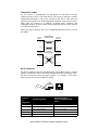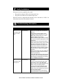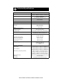
1
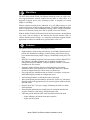
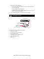
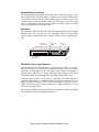
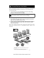
Start Here
The NETGEAR Model FS308 Fast Ethernet Switch provides you with a lowcost, high-performance network solution for the home or small office. It is
designed to support power users operating at either 10 megabits per second
(Mbps) or 100 Mbps.
Ethernet switches provide private, dedicated, 10 or 100 Mbps capacity to each
connected PC/server or hub/workgroup segment. The higher bandwidth enables
the use of applications such as multimedia, imaging, video, or high-performance
client-server functions among users who are spread out over the network.
With the Model FS308 Fast Ethernet Switch, this improvement is accomplished
very easily, with no change to the desktop (the network interface cards or
software and the network wiring). As a result, the performance upgrade and the
applications it enables are obtained very quickly and at a low cost.
Features
The Model FS308 switch has the following key features:
•
•
•
•
•
•
•
•
•
Eight automatic speed-sensing (autosensing) 10/100 Mbps Ethernet ports to
provide fast information exchange, resource sharing, and client or peer-topeer communication using simple Category 5 unshielded twisted pair (UTP)
cable
IEEE 802.3u standard compliance for interoperation with all 100BASE-TX
Fast Ethernet (100 Mbps) products, 802.3i standard compliance for
interoperation with all 10BASE-T Ethernet products, and 802.3x standard
compliance for flow control
Automatic address learning function to build the packet forwarding
information table, which contains up to 8,000 MAC addresses so that the
switch can support networks with as many as 8,000 devices
Easy plug-and-play installation with no software to configure, saving time
and minimizing the potential for configuration errors
Autosensing full-duplex or half-duplex mode of operation
Wire-speed filtering and forwarding to provide the “traffic cop” function by
directing traffic to the appropriate port or network segment without slowing
down the traffic
Internal 100 to 240 V AC power supply, eliminating the need for a bulky
wall transformer
Normal/Uplink push button to simplify network extension and allow the
switch to connect to a hub using a straight-through cable
LEDs that provide network traffic status and data transmission speed
— Status indicators on both the front and rear panels
— Eight vista RJ-45 ports
Model FS308 Fast Ethernet Switch Installation Guide
•
Home and small office friendliness
— Network ports located on the back of the hub so that cables are kept
away from the desktop
— Compact design to fit into small offices
— Compliance with the Class B EMI standard so the switch will not
interfere with your home appliances
•
5-year warranty on hub unit (1-year warranty on power supply)
Package Contents
Model FS308 switch
MODEL
Auto 10/100 Mbps
8
PORT
10/100Mbps
Fast Ethernet Switch
Power
Wall Mount
Installation kit
FS308
100 Link/Act.
10 Link/Act.
FDX/Col.
1
2
3
4
5
6
7
8
AC
power
cord
Installation guide,
Warranty & Owner
Registration Card,
Support Information Card
8920FA
Verify that your package contains the following:
•
•
•
•
•
•
Model FS308 switch
Mounting kit (for wall installation)
This installation guide
Warranty & Owner Registration Card
Support Information Card
Power cord
Model FS308 Fast Ethernet Switch Installation Guide
Product Illustration
Power LED
100 Link/Act
LEDs
MODEL
Auto 10/100 Mbps
8
PORT
10/100Mbps
FS308
100 Link/Act.
10 Link/Act.
FDX/Col.
Fast Ethernet Switch
Power
1
2
3
4
5
6
7
8
FDX/Col
LEDs
10 Link/Act
LEDs
8921FA
Front Panel
The front panel of the Model FS308 switch contains the following LEDs that
correspond to each network port located on the back of the hub: 100 Mbps link/
activity (100 Link/Act), 10 Mbps link/activity (10 Link/Act), and full-duplex/
collision (FDX/Col). Each vista RJ-45 network port has its own 100 Link/Act
and 10 Link/Act LED as well.
LEDs
The table below describes the activity of the LEDs.
Label
Color
Activity
Description
Pwr (Power)
Green
On
Off
Power is supplied to the switch.
Power is disconnected.
100 Link/Act
Green
On
The port is operating in 100 Mbps mode.
Data is being received or transmitted at 100
Mbps.
Blinking
10 Link/Act
Green
On
The port is operating in 10 Mbps mode.
Data is being received or transmitted at 10 Mbps.
Blinking
FDX/Col
Green
On
Yellow
Blinking
The port is operating in full-duplex mode.
A collision is occurring on the segment when the
port is operating in half-duplex mode. (Note that
some collisions are normal.)
Vista RJ-45 Network Ports with Built-in LEDs
All of the ports on the switch are 10/100 Mbps capable autosensing Ethernet
ports. Each port supports only unshielded twisted pair (UTP) cable using an 8pin RJ-45 plug. Each port uses vista RJ-45 connectors that have two LEDs—the
100 Link/Act LED and the 10 Link/Act LED.
100 Link/Act
10 Link/Act
8923EA
Model FS308 Fast Ethernet Switch Installation Guide
Normal/Uplink Push Button
The Normal/Uplink push button on the front panel of the switch allows you to
select uplink (MDI) or normal (MDI-X) wiring for port 8 on the Model FS308
switch. These ports are configured for normal wiring to connect to a PC when
the push button is in the out position. When the push button is pressed in, these
ports are configured for uplink wiring to connect to another switch or to a hub,
using a straight-through twisted pair cable.
Rear Panel
The rear panel of the Model FS308 switch has eight autosensing 10/100 Mbps
Ethernet ports. The rear panel also has full-duplex (FDX) and auto-duplex
(AUTO) toggle switches and a power adapter receptacle for the supplied power
cord.
vista RJ-45
network ports
100M
10M
Duplex Mode
switches
Power
receptacle
On = Link Blinking = Activity
Normal/Uplink
8765432
FDX
AUTO
8
7
6
5
4
3
2
1
Duplex Mode
100-240 VAC, 50-60Hz, 0.35A
Normal/Uplink
push button
8922FA
FDX/AUTO Duplex Toggle Switches
One full-duplex (FDX) and auto-duplex (AUTO) toggle switch is assigned to
each 10/100 Mbps port, enabling the communication mode to be set to either
full-duplex or auto-duplex mode. Full-duplex mode doubles throughput of
point-to-point connections by letting individual ports transmit and receive
concurrently when the connecting device also supports full-duplex mode.
Setting the toggle switch to AUTO on the 10/100 Mbps port enables the port to
determine duplex mode by coordinating with the remote port. In most cases, the
toggle switch should be set to AUTO. If the remote port is a repeater or hub or
cannot provide the proper signal to indicate its duplex capability, the port
defaults to half-duplex mode.
Set the port to full-duplex mode only if the remote device is full-duplex capable
but cannot provide the proper signal to indicate so.
Model FS308 Fast Ethernet Switch Installation Guide
Applications
The Model FS308 switch is designed to provide flexibility in configuring your
network connections. Each switch can be used as a standalone device or can be
used with 10 Mbps or 100 Mbps hubs or other interconnection devices in
various configurations. The configuration examples in this section illustrate the
integration of the switches in various network environments using other
NETGEAR products.
Desktop Switching
The Model FS308 switch is used as a desktop switch to build a small network
that enables users to have 100 Mbps access to a file server. If a full-duplex
adapter card is installed in the server or PC, a 200 Mbps connection is possible
on the port where the server or PC is connected.
Key
100 Mbps
10 Mbps
Model FS308 switch
100M
On = Link Blinking = Activity
10M
Normal/Uplink
8765432
FDX
AUTO
8
7
6
5
4
3
2
Duplex Mode
1
100-240 VAC, 50-60Hz, 0.35A
8924FA
Segment Switching and Bridging from 10 Mbps to 100 Mbps
The Model FS308 switch is used as a switch that segments a network into
multiple connected pieces, increasing overall bandwidth and throughput. The
Model FS308 switch can segment networks that are built with the NETGEAR
Model DS108 and Model EN104 hubs and can function as an eight-port bridge
connecting traditional 10BASE-T Ethernet networks to 100BASE-TX Fast
Ethernet networks.
Model FS308 switch
100M
On = Link Blinking = Activity
10M
Normal/Uplink
8765432
FDX
AUTO
8
Model DS108
hub
Auto 10/100 Mbps DUAL
7
6
5
4
3
2
1
Duplex Mode
100-240 VAC, 50-60Hz, 0.35A
Model RT328
router
Model EN104
hub
SPEED
8925FA
Model FS308 Fast Ethernet Switch Installation Guide
Prepare the Site
Before you begin installing your switch, prepare the installation site. Make sure
your operating environment meets the operating environment requirements of
the equipment.
Characteristic
Requirement
Temperature
Ambient temperature between 0° and 40° C (32° and 104° F).
No nearby heat sources such as direct sunlight, warm air
exhausts, or heaters.
Operating humidity
Maximum relative humidity of 90%, noncondensing.
Ventilation
Minimum 2 inches (5.08 cm) on all sides for cooling.
Adequate airflow in room or wiring closet.
Operating conditions
At least 6 feet (1.83 m) to nearest source of electromagnetic
noise (such as photocopy machine or arc welder).
Power
Adequate power source within 6 feet (1.83 m).
Install the Switch
To install your switch on a flat surface, you do not need any special tools. Be
sure the switch is positioned with at least 2 inches of space on all sides for
ventilation.
To install the switch on a wall, measure the distance between the mounting holes
on the back of the switch and mark the wall to match the location of the
mounting holes on the switch. At the marked location, screw into the wall the
two screws that you received with the mounting kit included in your package
contents. Be sure to choose a location that is near the devices to be connected, is
close to an electrical outlet, and provides at least 2 inches of space all around the
switch for ventilation.
Model FS308 Fast Ethernet Switch Installation Guide
Connect Devices to the Switch
Before connecting the switch, be sure you review “Applications” for information
about determining the appropriate configuration for your networking needs.
To connect the switch:
1. Connect the devices to the 10/100 Mbps ports on the switch, using
Category 5 UTP cable and an RJ-45 plug.
Note: Ethernet specifications limit the cable length between your PC or
server and the switch to 328 feet (100 meters) in length.
2. Set the Normal/Uplink push button.
3. Set the FDX/AUTO toggle switches on the rear panel for the selected
duplex mode (the default setting is AUTO).
4. Connect one end of the DC power adapter cable to the power outlet on
the rear panel of the switch and the other end of the power adapter
cable to the wall outlet.
Refer to the following illustration when connecting the Model FS308 switch.
Each of the preceding steps has a corresponding reference number in the
illustration.
Key
100 Mbps
10 Mbps
RJ-45
connector
1
Normal/U
plink
1
8
Duple
x Mode
2
*
3
Normal/
Uplink
**
4
1
8
Duple
x Mod
*
**
FDX
AUTO
e
FDX
AUTO
Normal/Uplink push button set to the Normal position for connection
to the server.
For a typical configuration, set toggle switches to AUTO. For more
information, refer to "FDX/AUTO Duplex Toggle Switches."
8935FA
Model FS308 Fast Ethernet Switch Installation Guide
Twisted Pair Cables
For two devices to communicate, the transmitter of each device must be
connected to the receiver of the other device. The crossover function is usually
implemented internally as part of the circuitry in the device. Most ports on
switches and repeaters have media-dependent interfaces with crossover ports.
These ports are referred to as MDI-X or normal ports. Computer and
workstation adapter cards are usually media-dependent interface ports referred
to as MDI or uplink ports.
These two figures illustrate the use of straight-through and crossover twisted
pair cables.
Uplink or
MDI port
Tx
Rx
Straight-through
twisted pair cable
Normal or
MDI-X port
1
1
2
2
3
3
6
6
Normal or
MDI-X port
Crossover
twisted pair cable
Rx
Tx
Normal or
MDI-X port
Rx
1
2
1
Rx
2
Tx
3
6
3
Tx
6
8146EC
RJ-45 Connector
The RJ-45 connector (shown in the illustration with an RJ-45 plug) is used to
connect workstations, hubs, and switches through unshielded twisted pair cable.
The RJ-45 connector accepts four-pair Category 3 or Category 5 UTP cable.
Only two pairs are used for 10BASE-T wiring.
12345678
8
1
711EA
RJ-45
Connector
Pin
Assignment
Normal Assignment:
Uplink Assignment:
Port 8 on the Model FS308
switch
1
Input Receive Data +
Output Transmit Data +
2
Input Receive Data -
Output Transmit Data -
3
Output Transmit Data +
Input Receive Data +
6
Output Transmit Data -
Input Receive Data -
4,5,7,8
Not used
Not used
Model FS308 Fast Ethernet Switch Installation Guide
Verify Installation
When power has been applied to the switch:
•
•
The green Pwr (Power) LED on the front panel is on.
The green Link LED on each connected port is on.
When the switch is connected and operating, refer to the table in “LEDs” for
information about the LEDs and their activity.
Troubleshooting Information
Symptom
Cause
Solution
100 Link/Act LED Port connection is
or
not functioning.
10 Link/Act LED is
off on an active
port.
Make sure the attached device is powered
and there is a proper UTP connection at
that end.
Verify that the network adapter card is
installed correctly and that the 10 or 100
Mbps LED and Link LEDs are on at the
network adapter card in the PC.
Make sure that the proper cable is installed,
and check for miswired cable pairs or loose
connectors.
Make sure the port termination at both the
switch and the device end is correct. Check
the crimp on the RJ-45 connectors. In a
Fast Ethernet operation, the quality of the
crimp on the connector is important. It is
also important that only Category 5 cable is
used and that it is certified for 100 Mbps
operation.
Make sure the length of the UTP cable from
the switch to the device does not exceed
328 feet (100 meters).
Using cable test equipment, make sure that
the cable meets the crosstalk, attenuation,
and impedance specifications as required
by the 100BASE-TX standard.
100 Link/Act LED Port connection is
or
not functioning.
10 Link/Act LED is
off on port 8.
Check the Normal/Uplink push button on the
front panel.
If you are using a straight-through cable
connected to a PC or other MDI-wired
device, make sure the Normal/Uplink push
button is set in the Normal position.
If you are using a straight-through cable
connected to a router or another switch,
make sure the Normal/Uplink push button is
set in the Uplink position.
Try the alternate position of the Normal/
Uplink push button to turn the Link LED on.
Model FS308 Fast Ethernet Switch Installation Guide
Symptom
Cause
Solution
100 Link/Act LED Port is operating in
is off when
10 Mbps mode.
operating in a Fast
Ethernet network.
Make sure the adapter card is capable of
100 Mbps operation and set for 100 Mbps
operation if it is not autosensing.
100 Link/Act LED Port is operating in
or
half-duplex mode.
10 Link/Act LED is
on and bicolor
FDX LED is off
when operating in
a Fast Ethernet
network.
Make sure the duplex switch on the Model
FS308 Fast Ethernet Switch is set for fullduplex operation. Make sure the connected
device is capable of full-duplex
transmission.
Bicolor FDX
Collision LED is
blinking yellow.
The port and switch might be functioning
correctly. Data collisions are normal on
Ethernet networks and occur when two or
more computers transmit data on the
network simultaneously. Computers that
caused the collision retry transmission at
different intervals until the transmission
succeeds. Excessive collisions can result
when multiple switches are connected and
when many computers are connected on
the network. Check and make sure that
cabling and duplex settings are correct.
Data collision is
occurring on the
port.
Model FS308 Fast Ethernet Switch Installation Guide
Technical Specifications
General Specifications
Model FS308 Fast Ethernet Switch
Network Protocol and Standards Compatibility
ISO/IEC 802-3 (ANSI/IEEE 802.3i) 10BASE-T Ethernet
IEEE 802.3u, IEEE802.3x 100BASE-TX Fast Ethernet
Data Rate
100 Mbps with 4B/5B encoding and MLT-3 physical
interface for 100BASE-TX
10 Mbps differential Manchester encoded
Interface
RJ-45 connector for 10BASE-T or 100BASE-TX
Ethernet interface
Power Consumption
Input Voltage (Power Adapter)
15.2 W
100-240 V AC
Physical Specifications
Dimensions:
9.95 x 1.38 x 7.05 in.
25.3 x 3.5 x 17.9 cm
Weight:
3.0 lb; 1.4 kg
Environmental Specifications
Operating temperature:
Operating humidity:
Electromagnetic Emissions
0° to 40° C (32° to 104° F)
90% maximum relative humidity, noncondensing
CE mark, commercial; FCC Part 15 Class B; EN 55
022 (CISPR 22), Class B; VCCI Class 1 ITE
Electromagnetic Susceptibility
CE mark, commercial
Electrostatic discharge (ESD):
IEC 801-2, Level 2/3/4
Radiated electromagnetic field:
IEC 801-3, Level 2
Electrical fast transient/burst:
IEC 801-4, Level 2
Electrical surge:
IEC 801-5, Level 2
Safety Agency Approvals for Power Adapter
CE mark, commercial
UL listed (UL 1950), cUL
TUV licensed (EN 60 950)
T-Mark
Performance Specifications
Frame filter rate:
14,800 frames/second, maximum on 10 Mbps port
148,000 frames/second, maximum on 100 Mbps port
Frame forward rate:
14,800 frames/second, maximum on 10 Mbps port
148,000 frames/second, maximum on 100 Mbps port
Network latency (using 64 byte packets):
10 Mbps to 10 Mbps: 73 microseconds maximum
10 Mbps to 100 Mbps: 26 microseconds maximum
100 Mbps to 10 Mbps: 62 microseconds maximum
100 Mbps to 100 Mbps: 15 microseconds maximum
Address database size:
Addressing:
Queue buffer:
8,000 media access control (MAC) addresses per port
48-bit MAC address
128 Kilobytes of buffer space for each port
Model FS308 Fast Ethernet Switch Installation Guide
© 1998 by NETGEAR, Inc. All rights reserved.
Trademarks
Bay Networks is a registered trademark of Bay Networks, Inc.
NETGEAR is a trademark of Bay Networks, Inc.
All other trademarks and registered trademarks are the property of their respective owners.
Statement of Conditions
In the interest of improving internal design, operational function, and/or reliability, NETGEAR
reserves the right to make changes to the products described in this document without notice.
NETGEAR does not assume any liability that may occur due to the use or application of the
product(s) or circuit layout(s) described herein.
Certificate of the Manufacturer/Importer
It is hereby certified that the NETGEAR Model FS308 Fast Ethernet Switch has been suppressed
in accordance with the conditions set out in the BMPT-AmtsblVfg 243/1991 and Vfg 46/1992.
The operation of some equipment (for example, test transmitters) in accordance with the
regulations may, however, be subject to certain restrictions. Please refer to the notes in the
operating instructions.
Federal Office for Telecommunications Approvals has been notified of the placing of this
equipment on the market and has been granted the right to test the series for compliance with the
regulations.
Voluntary Control Council for Interference (VCCI) Statement
This equipment is in the first category (information equipment to be used in commercial and/or
industrial areas) and conforms to the standards set by the Voluntary Control Council for
Interference by Data Processing Equipment and Electronic Office Machines that are aimed at
preventing radio interference in commercial and/or industrial areas.
Consequently, when this equipment is used in a residential area or in an adjacent area thereto,
radio interference may be caused to equipment such as radios and TV receivers.
Federal Communications Commission (FCC) Compliance Notice: Radio Frequency
Notice
This device complies with part 15 of the FCC Rules. Operation is subject to the following two
conditions:
•
This device may not cause harmful interference.
•
This device must accept any interference received, including interference that may cause
undesired operation.
Note: This equipment has been tested and found to comply with the limits for a Class B digital
device, pursuant to part 15 of the FCC Rules. These limits are designed to provide reasonable
protection against harmful interference in a residential installation. This equipment generates,
uses, and can radiate radio frequency energy and, if not installed and used in accordance with the
instructions, may cause harmful interference to radio communications. However, there is no
guarantee that interference will not occur in a particular installation. If this equipment does cause
harmful interference to radio or television reception, which can be determined by turning the
equipment off and on, the user is encouraged to try to correct the interference by one or more of
the following measures:
•
Reorient or relocate the receiving antenna.
•
Increase the separation between the equipment and receiver.
•
Connect the equipment into an outlet on a circuit different from that to which the receiver is
connected.
•
Consult the dealer or an experienced radio/TV technician for help.
Model FS308 Fast Ethernet Switch Installation Guide
EN 55 022 Declaration of Conformance
This is to certify that the NETGEAR Model FS308 Fast Ethernet Switch is shielded against the
generation of radio interference in accordance with the application of Council Directive 89/336/
EEC, Article 4a. Conformity is declared by the application of EN 55 022 Class B (CISPR 22).
Canadian Department of Communications Radio Interference Regulations
This digital apparatus (NETGEAR Model FS308 Fast Ethernet Switch) does not exceed the Class
B limits for radio-noise emissions from digital apparatus as set out in the Radio Interference
Regulations of the Canadian Department of Communications.
Règlement sur le brouillage radioélectrique du ministère des Communications
Cet appareil numérique (NETGEAR Model FS308 Fast Ethernet Switch) respecte les limites de
bruits radioélectriques visant les appareils numériques de classe B prescrites dans le Règlement
sur le brouillage radioélectrique du ministère des Communications du Canada.
Model FS308 Fast Ethernet Switch Installation Guide
NETGEAR, Inc.
A Bay Networks Company
4401 Great America Parkway
Santa Clara, CA 95054 USA
Phone: 888-NETGEAR
*M-FS308NA-1*
Model FS308 Fast Ethernet Switch Installation Guide