1
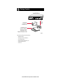
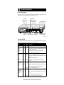
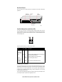
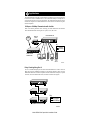
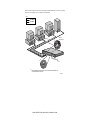
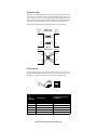
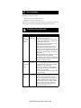
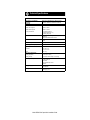
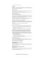
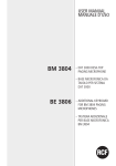
Start Here
Start Here
The NETGEAR™ Model DS309 Dual Speed Hub is a network hub that enables users to mix and
match 10 and 100 megabit per second (Mbps) devices on the same network. This capability
eliminates the high cost and complexity of separate network equipment for 10 and 100 Mbps
users. The Model DS309 hub is ideal for small networks in transition from 10 to 100 Mbps and for
linking networks operating at different speeds.
The hub connects PCs to share printers, files, Internet access, and e-mail communications. Each
network port coordinates with the connected PC to run at 10 or 100 Mbps, making network
configuration and upgrade effortless. In addition, the 10 and 100 Mbps network segments are
internally bridged to form one network, providing full connectivity among all users.
Features
Features
The Model DS309 Dual Speed Hub has the following key features:
•
•
•
•
•
•
•
Nine autosensing, dual-speed (10/100 Mbps) ports
– Internally bridged 10 and 100 Mbps network segments to form one network, providing full
connectivity among all users
– One switched port that enables the Model DS309 hub to cascade to other 100 Mbps hubs,
bypassing 100BASE-TX limitations
Ability of each port on the hub to independently detect the speed of the attached device and
to automatically connect at the appropriate speed
IEEE 802.3u standard compliance for interoperation with all 100BASE-TX Fast Ethernet
(100 Mbps) products and 802.3i standard compliance for interoperation with all 10BASE-T
Ethernet products
Easy Plug-and-Play installation with no software to configure, saving time and minimizing
the potential for configuration errors
Chassis equipped with:
– Status indicators on both the front and rear panels
– Built-in vista LEDs on each network port clearly indicating individual port status
– Additional LEDs providing network traffic status for the hub
– Two LED bar graphs providing online status of network utilization and alerting you to
potential network overload
– Normal/Uplink push button for simplifying network extension
Design planned for home and small office use
– Network ports located on the back of the hub so that cables are kept away from the desktop
– Compact design to fit into small offices
– Compliance with the Class B EMI standard so the hub does not interfere with your home
appliances
5-year warranty on hub unit (1-year warranty on power supply)
Model DS309 Dual Speed Hub Installation Guide
Package Contents
Package Contents
Model DS309 hub
Auto 10/100 Mbps
9
PORT
10/100Mbps
Dual SPEED
Switched
10Link/Rx
MODEL
DS309
100M
Dual Speed Hub
1%
PWR
8%
16% 32%
1
2
3
4
5
6
7
8
9
10M
COL
Utilization
Link/Rx
Wall Mount
Installation kit
Link/Act
AC
power
cord
Installation guide,
Warranty & Owner
Registration Card,
Support Information Card
9004FA
Verify that your package contains the following:
•
•
•
•
•
•
Model DS309 hub
Mounting kit (for wall installation)
This installation guide
Warranty & Owner Registration Card
Support Information Card
Power cord
Model DS309 Dual Speed Hub Installation Guide
Product Illustration
Product Illustration
Front Panel Features
On the front panel are LEDS that provide information about network traffic status, show data
transmission speed, and indicate when power is supplied to the hub.
%Utilization
LEDs (100 Mbps)
Col LED
(100 Mbps)
Power
LED
Link/Rx LEDs
(100 Mbps)
Auto 10/100 Mbps
Dual
9
SPEED
Switched Link/Act
LED (100 Mbps)
MODEL
DS309
Switched
10Link/Rx
100M
PORT
Dual Speed Hub
1%
10/100Mbps
8%
16% 32%
1
2
3
4
5
6
7
8
9
10M
PWR
COL
Col LED
(10 Mbps)
Utilization
%Utilization
LEDs (10 Mbps)
Link/Rx
Link/Rx LEDs
(10 Mbps)
Link/Act
Switched Link/Act
LED (10 Mbps)
9005FA
Front Panel LEDs
The Model DS309 hub provides front panel LEDs for monitoring individual ports and hub status.
The following table describes the front panel LEDs and their functions.
Label
Color
Activity Description
Pwr (Power)
Green
On
Power is supplied to the hub.
10 Mbps
Amber
On
Data collision is occurring on the 10 Mbps network segment
(some collisions are normal).
100 Mbps
Amber
On
Data collision is occurring on the 100 Mbps network
segment (some collisions are normal).
10 Mbps
Green
Blinking
Indicates the amount of data traffic on the 10 Mbps
segment. (If a 100 Mbps user is sending data to a 10 Mbps
user, the
10 Mbps utilization will be high.)
100 Mbps
Green
Blinking
Indicates the amount of data traffic on the 100 Mbps
segment.
Link/Rx
10M or 100M
(ports 1 to 8)
Green
On
A link is successfully established between the hub and the
PC.
Off
No link exists between the port and the network.
Blinking
There is incoming data on the port.
On
A link is successfully established between the hub and the
PC.
Off
No link exists between the port and the network.
Blinking
There is incoming or outgoing data on the port.
Col (Collision)
Utilization%
Switched
Link/Activity
10M or 100M
(port 9)
Green
Model DS309 Dual Speed Hub Installation Guide
Rear Panel Features
On the rear panel are the vista RJ-45 network ports with built-in LEDs and the Normal/Uplink
push button.
vista RJ-45
network ports
100M
On = Link Blinking = Activity
10M
8
7
6
5
4
3
2
Switched
port
On=Link, Blinking=Act
100M 10M
1
Power
receptacle
Normal/Uplink
Switched
100-240 VAC, 50-60Hz, 0.35A
Normal/Uplink
push button
9007FA
Vista RJ-45 Network Ports with Built-in LEDs
All of the ports on the hub are 10/100 Mbps capable autosensing Ethernet ports. Each port
supports unshielded twisted pair (UTP) or shielded twisted pair (STP) cable using an 8-pin RJ-45
plug. Each port uses vista RJ-45 connectors that have two LEDs—the 100M (100 Mbps) LED and
the 10M (10 Mbps) LED.
100M
10M
9006EA
The following table describes the vista RJ-45 connector LEDs.
Label
Color
Activity Description
10M or 100M
(On vista
connectors for
port 1 through
port 9)
Green
On
A link is successfully established between the Switched port
on the hub and the connected port.
Off
No link exists between the port and the network.
On port 1
through port 8
Blinking
There is incoming data on the port.
On Switched
port (port 9)
Blinking
There is incoming or outgoing data on the port.
Normal/Uplink Push Button
The Normal/Uplink push button on the rear panel of the Model DS309 hub allows you to select
uplink (MDI) or normal (MDI-X) wiring for port 9 on the hub. The port is configured for normal
wiring to connect to a PC when the push button is in the out position. When the push button is
pressed in, the port is configured for uplink wiring to connect to another hub or to a switch, using
a straight-through twisted pair cable.
The rear panel of the Model DS309 hub has nine automatic speed-sensing 10/100 Mbps network
ports and a power adapter receptacle for the supplied power cord.
Model DS309 Dual Speed Hub Installation Guide
Applications
Applications
The Model DS309 hub is designed to provide flexibility in configuring your network connections.
Each hub can be used as a standalone device or can be used with 10 Mbps or 100 Mbps hubs or
other interconnection devices in various configurations. The configuration examples in this section
illustrate the integration of the Model DS309 hub in various network environments using other
NETGEAR products.
10 Mbps or 100 Mbps Transmission with the Hub
Refer to the following illustration when connecting your Model DS309 hub. The illustration
shows a Model DS309 hub connecting users to a printer, servers, and a router.
Model DS309 hub
Network
printer
ISDN
100M
On = Link Blinking = Activity
10M
Switched
Normal/Uplink
8
7
6
5
4
3
2
1
9
100-240 VAC, 50-60Hz, 0.35A
Key
10 Mbps
100 Mbps
Model RT328
ISDN Router
PCs
PC
server
Power
user
Power
user
server
9008FA
Daisy Chaining Using Port 9
Port 9 is a switched half-duplex port that enables the Model DS309 hub to cascade to other 100
Mbps hubs, bypassing 100BASE-TX limitations. The following illustration shows how three
Model DS309 hubs can be cascaded to expand the network. Without the Switched port, a separate
switch unit, such as the Model FS308 switch, is needed to cascade the units together.
100-240 VAC, 50-60Hz, 0.35A
100-240 VAC, 50-60Hz, 0.35A
Key
10 Mbps
100 Mbps
100-240 VAC, 50-60Hz, 0.35A
Model DS309 hubs
9010FA
Model DS309 Dual Speed Hub Installation Guide
1. Prepare the Site
Prepare the Site
Before you begin installing your Model DS309 hub, prepare the installation site. Make sure your
operating environment meets the operating environment requirements of the equipment.
Characteristic
Requirement
Temperature
Ambient temperature between 0° and 40° C (32° and 104° F).
No nearby heat sources such as direct sunlight, warm air exhausts, or
heaters.
Operating humidity
Maximum relative humidity of 90%, noncondensing.
Ventilation
Minimum 2 inches (5.08 cm) on all sides for cooling.
Adequate airflow in room or wiring closet.
Operating conditions
At least 6 feet (1.83 m) to nearest source of electromagnetic noise (such
as photocopy machine or arc welder).
Power
Adequate power source within 6 feet (1.83 m).
2. Install the Hub
Install the Hub
To install your hub on a flat surface, you do not need any special tools. Be sure the hub is
positioned with at least 2 inches of space on all sides for ventilation.
To install the hub on a wall, measure the distance between the mounting holes on the back of the
hub and mark the wall to match the location of the mounting holes on the device. At the marked
location, screw into the wall the two screws that you received with the mounting kit included in
your package contents. Be sure to choose a location that is near the devices to be connected, is
close to an electrical outlet, and provides at least 2 inches of space all around the hub for
ventilation.
3. Connect Devices to the Hub
Connect Devices to the Hub
Before connecting the hub, be sure you review “Applications” for information about determining
the appropriate configuration for your networking needs.
To connect the hub:
1.
Connect the devices to the 10/100 Mbps ports on the hub, using Category 5 UTP cable
with an RJ-45 plug.
Note: Ethernet specifications limit the cable length between your PC or server and
the hub to 328 feet (100 meters) in length.
2.
3.
Set the Normal/Uplink push button.
Connect one end of the DC power adapter cable to the power outlet on the rear panel of
the hub and the other end of the power adapter cable to the wall outlet.
Model DS309 Dual Speed Hub Installation Guide
Refer to the following illustration when connecting the Model DS309 hub. Each of the preceding
steps has a corresponding reference number in the illustration.
Key
100 Mbps
10 Mbps
RJ-45
connector
1
Norma
l/Uplin
k
2
*
3
Normal
/Uplin
*
k
Normal/Uplink push button set to the Normal position for
connection to the server.
9011FA
Model DS309 Dual Speed Hub Installation Guide
Twisted Pair Cables
For two devices to communicate, the transmitter of each device must be connected to the receiver
of the other device. The crossover function is usually implemented internally as part of the
circuitry in the device. Most ports on hubs and repeaters have media-dependent interfaces with
crossover ports. These ports are referred to as MDI-X or normal ports. Computer and workstation
adapter cards are usually media-dependent interface ports referred to as MDI or uplink ports.
These two figures illustrate the use of straight-through and crossover twisted pair cables.
Uplink or
MDI port
Tx
Rx
Straight-through
twisted pair cable
Normal or
MDI-X port
1
1
2
2
3
3
6
6
Normal or
MDI-X port
Crossover
twisted pair cable
Rx
Tx
Normal or
MDI-X port
Rx
1
2
1
Rx
2
Tx
3
6
3
Tx
6
8146EC
RJ-45 Connector
The RJ-45 connector (shown in the illustration with an RJ-45 plug) is used to connect
workstations and hubs through unshielded twisted pair cable. The RJ-45 connector accepts fourpair Category 3 or Category 5 UTP cable. Only two pairs are used for 10BASE-T wiring.
12345678
8
1
711EA
RJ-45
Normal Assignment:
Connector
Pin Assignment
Uplink Assignment: Port 9 on the
Model DS309 Hub
1
Input Receive Data +
Output Transmit Data +
2
Input Receive Data -
Output Transmit Data -
3
Output Transmit Data +
Input Receive Data +
6
Output Transmit Data -
Input Receive Data -
4,5,7,8
Not used
Not used
Model DS309 Dual Speed Hub Installation Guide
4. Verify Installation
Verify Installation
When power has been applied to the hub:
•
•
The green Pwr (Power) LED on the front panel is on.
The green Link LED on each connected port is on.
When the hub is connected and operating, refer to the tables in “Front Panel LEDs” and “Vista RJ45 Network Ports with Built-in LEDs” for information about the LEDs and their activity.
Troubleshooting Information
Troubleshooting Information
Symptom
Cause
Solution
100 Link/Rx
LED or
10 Link/Rx LED
is off on an
active port.
Port connection is
not functioning.
Make sure the attached device is powered on and there is a
proper UTP connection at that end.
Verify that the network adapter card is installed correctly
and that the 10 or 100 Mbps LED and Link LEDs are on at
the network adapter card in the PC.
Make sure that the proper cable is installed, and check for
miswired cable pairs or loose connectors.
Make sure the port termination at both the hub and the
device end is correct. Check the crimp on the RJ-45
connectors. In a Fast Ethernet operation, the quality of the
crimp on the connector is important. It is also important that
only Category 5 cable is used and that it is certified for 100
Mbps operation.
Make sure the length of the UTP cable from the hub to the
device does not exceed 328 feet (100 meters).
Using cable test equipment, make sure that the cable meets
the crosstalk, attenuation, and impedance specifications as
required by the 100BASE-TX standard.
100 Link/Act
Port connection is
LED or
not functioning.
10 Link/Act LED
is off
on port 9.
Check the Normal/Uplink push button on the front panel.
If you are using a straight-through cable connected to a PC
or other MDI-wired device, make sure the Normal/Uplink
push button is set in the Normal position.
If you are using a straight-through cable connected to a
router or another hub, make sure the Normal/Uplink push
button is set in the Uplink position.
Try the alternate position of the Normal/Uplink push button
to turn the Link LED on.
Col (Collision)
LED is on or
blinking.
The port and hub might be functioning correctly. Data
collisions are normal on Ethernet networks and occur when
two or more computers transmit data on the network
simultaneously. Computers that caused the collision retry
transmission at different intervals until the transmission
succeeds. Excessive collisions can result when multiple
hubs are connected and when many computers are
connected on the network. Check and make sure that
cabling and duplex settings are correct.
Data collision is
occurring on the
port.
Model DS309 Dual Speed Hub Installation Guide
Technical Specifications
Technical Specifications
General Specifications
Network Protocol and Standards
Compatibility
ISO/IEC 802-3 (ANSI/IEEE 802.3i) 10BASE-T Ethernet
IEEE 802.3u, IEEE802.3x 100BASE-TX Fast Ethernet
Status LEDs
Unit
Power
10 Mbps network segment
Utilization %,collision
100 Mbps network segment
Utilization %, collision
Per UTP port status LED
10 or 100 Mbps operations
Link, Receive data (ports 1— 8)
Link, Activity data (port 9)
Data Rate
100 Mbps with 4B/5B encoding and MLT-3 physical interface for
100BASE-TX
10 Mbps differential Manchester encoded
Interface
RJ-45 connector for 10BASE-T or 100BASE-TX Ethernet
interface
Power Consumption
0.35 Amp, Maximum
Input Voltage (Power Adapter)
100—240 V AC
Physical Specifications
Dimensions:
9.27 x 1.06 x 4.1 in.
25.3 x 3.5 x 17.9 cm
Weight:
2.8 lb; 1.3 kg
Environmental Specifications
Operating temperature:
0° to 40° C (32° to 104° F)
Operating humidity:
90% maximum relative humidity, noncondensing
Electromagnetic Compliance
CE mark, commercial
FCC Part 15 Class B
VCCI Class B
EN 55 022 (CISPR 22), Class B
EN50082-1
Safety Agency Approvals
UL listed (UL 1950)/cUL
IEC950/EN60950
Warranty
Hub: 5 years
Power supply: 1 year
Model DS309 Dual Speed Hub Installation Guide
© 2000 by NETGEAR, Inc. All rights reserved.
Trademarks
NETGEAR™ is a trademark of NETGEAR, Inc. Windows® is a registered trademark of Microsoft
Corporation. Other brand and product names are trademarks or registered trademarks of their respective
holders. Information is subject to change without notice.
Statement of Conditions
In the interest of improving internal design, operational function, and/or reliability, NETGEAR reserves the
right to make changes to the products described in this document without notice.
NETGEAR does not assume any liability that may occur due to the use or application of the product(s) or
circuit layout(s) described herein.
Certificate of the Manufacturer/Importer
It is hereby certified that the NETGEAR Model DS309 Dual Speed Hub has been suppressed in accordance
with the conditions set out in the BMPT-AmtsblVfg 243/1991 and Vfg 46/1992. The operation of some
equipment (for example, test transmitters) in accordance with the regulations may, however, be subject to
certain restrictions. Please refer to the notes in the operating instructions.
Federal Office for Telecommunications Approvals has been notified of the placing of this equipment on the
market and has been granted the right to test the series for compliance with the regulations.
Voluntary Control Council for Interference (VCCI-2) Statement
This equipment is in the 2nd Class category (information equipment to be used in a residential area or an
adjacent area thereto) and conforms to the standards set by the Voluntary Control for Interference by Data
Processing Equipment and Electronic Office Machines aimed at preventing radio interference in such
residential areas.
When used near a radio or TV receiver, it may become the cause for radio interference.
Read instructions for correct handling.
Federal Communications Commission (FCC) Compliance Notice: Radio Frequency Notice
This device complies with part 15 of the FCC Rules. Operation is subject to the following two conditions:
•
This device may not cause harmful interference.
•
This device must accept any interference received, including interference that may cause undesired
operation.
Note: This equipment has been tested and found to comply with the limits for a Class B digital device,
pursuant to part 15 of the FCC Rules. These limits are designed to provide reasonable protection against
harmful interference in a residential installation. This equipment generates, uses, and can radiate radio
frequency energy and, if not installed and used in accordance with the instructions, may cause harmful
interference to radio communications. However, there is no guarantee that interference will not occur in a
particular installation. If this equipment does cause harmful interference to radio or television reception, which
can be determined by turning the equipment off and on, the user is encouraged to try to correct the interference
by one or more of the following measures:
•
Reorient or relocate the receiving antenna.
•
Increase the separation between the equipment and receiver.
•
Connect the equipment into an outlet on a circuit different from that to which the receiver is connected.
•
Consult the dealer or an experienced radio/TV technician for help.
EN 55 022 Declaration of Conformance
This is to certify that the NETGEAR Model DS309 Dual Speed Hub is shielded against the generation of radio
interference in accordance with the application of Council Directive 89/336/EEC, Article 4a. Conformity is
declared by the application of EN 55 022 Class B (CISPR 22).
Compliance is dependent upon the use of shielded cables.
Canadian Department of Communications Radio
Interference Regulations
This digital apparatus (NETGEAR Model DS309 Dual Speed Hub) does not exceed the Class B limits for
radio-noise emissions from digital apparatus as set out in the Radio Interference Regulations of the Canadian
Department of Communications.
Règlement sur le brouillage radioélectrique du ministère
des Communications
Cet appareil numérique (NETGEAR Model DS309 Dual Speed Hub) respecte les limites de bruits radioélectriques visant les appareils numériques de classe B prescrites dans le Règlement sur le brouillage radioélectrique du ministère des Communications du Canada.
Model DS309 Dual Speed Hub Installation Guide
NETGEAR, Inc.
4500 Great America Parkway
Santa Clara, CA 95054
USA
Phone: 1-888-NETGEAR
E-mail: [email protected]
www.NETGEAR.com
*M-DS309NA-1*
Model DS309 Dual Speed Hub Installation Guide