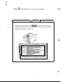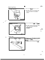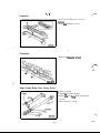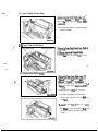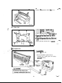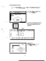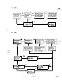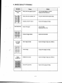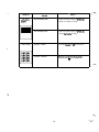
1
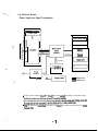
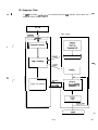
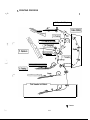
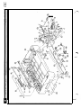
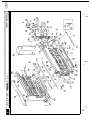
SP-A310
Service & Parts Manual
September 1996 +-’
Revision C-02
WARNING LABELS
-
i
SAFETY INFORMATlON
.
ALL Areas
INTERNAL LASER RADIATION
Maximum radiation power: 8.8 x lo4 (W)
Wavelength: 770-8 10 MI
This is a Class Bib Laser Diode Assy. that has an invisible Laser Beam. The Print Head
Unit is NOT A FIELD SERVICE ITEM. Therefore, the Print Head Unit should not be
opened under any circumstances.
U.S.A. Only
LASER SAFETY
This LBP printer is certified as a Class 1 laser product under the U.S. Department of Health
and Human Services (DHHS) Radiation Performance Standard according to the Food, Drug
and Cosmetic Act of 1990. This means that the LBP printer does not produce hazardous laser
radiation.
Since radiation emitted inside the LBP printer is completely confined within protective
housing and external covers, the laser beam cannot escape from the LBP printer during
any phase of user operation.
CDRH REGULATIONS
The Center for Devices and R&ological Health (CDRH) of the U.S. Food and Drug
Administration implemented regulations for laser products on August 2, 1976. These
regulations apply to laser products manufactured from August 1, 1976. Compliance is
mandatory for products marketed in the United States. The label shown in the figure
indicates compliance with the CDRH regulations and must be attached to laser products
marketed in the United States-.
CLASSIFICATION OF THE LASER PRODUCT
This product is classified as a Class 1 Laser Product under the CDRH Regulations U.S.A..
CAUTION
Danger of explosion if battery is incorrectly replaced.
Replace only with the same or equivalent type recommended by the manufacturer.
Discard used batteries according to manufacture’s instructions.
ii
.
Denmark Only
ADVARSEL!
Lithiumbatteri-Eksplosionsfare ved fejlagtig hhdtering.
Udskifining m4 kun ske med batteri af samme fabrikat og type.
Lever det brugte batter-i tilbage til leverandoren.
Norway Only
ADVARSEL
Lithiumbatteri-Bksplosjonsfare.
Ved utskifting benyttes kun batter-i som anbefalt av apparatfabrikanten.
Brukt batteri retumeres apparatleverand@ren.
(
-.
Sweden Only
VARNING
Explosionsfara vid felaktigt bat&byte.
AMind samma batterityp eller en ekvivalent
typ som rekommenderas av apparativerkaren.
Kassera anvXnt batter-i enligt fabrikantens in&&ion.
VARNING!
Osynlig laserstr&ting n3r denna de1 ar oppnad och sp&-ren 2r urkopplad.
Behakta ej St&en.
Finland Only
VAROITIJS
Pristo voi r&jahM jos se on virheellisesti asennettu.
Vaihda paristo ainoastaan laitevalmistajan suosittelemaan
tyyppiin. H&vita tiytetty paristo valmistajan ohjeiden
mukaisesti.
.,
1-
VARO!
Avattaessa ja suojalulcitus ohitettasessa olet ahtiina n&ymatt(lmtie lasersateilylle.
&4 katso sateeseen.
New Zealand Only
Warning
“Immediately disconnect the equipment should it become physically damaged, and arrange
for its disposal or repair before reconnecting.”
“Disconnect the Telecom Network connection before disconnecting the Power connection
prior to relocating the equipment, and reconnect the Poker first.”
User Instruction (For all users)
The outlet should be located near the printer and should be easily accessible.
...
III
>,.--
)‘ 1
_-
.
Please read the following for your own protection.
I
C
A Caution
1
Opening the cover indicated by the Caution label below may expose you to
harmful laser radiation which could cause damage or loss of eyesight. Do not
Open the Cover when the power is on.
iv
PRECAUTIONS
(1) Precautlbns
Refer to D: DISASSEMBLY/ CLEANING for the Disassembly procedure.
Be sure to unplug the printer befcre disassembling and cleauing.
pczzi&q
1. When unplugging ccumec tors on the P.WI3.s themselves, always make sum the power is OFF first.
2. Always unplug conrxctors by holding the connector housing. Pulling on the power cord can lead
to problems with poor contact.
3.Itisrec canmended that a body ground not be used when carrying out any trouble-shooting
procedure. Be sure to ground DC lines to a ground test point on the P.W.B.
pGiq
(2) At Replacement/ Adjustment/ Cleaning
l.BesuretohandletheFusingUnitcarefullyastheunitisstillhotforawhileafbertheprinteris
stopped;t:
2. Do not disassemble the Imaging Cartridge or the Print Head Unit
3.UseonlyaPuseoftheindicatedrating.
(3) During Operation
A Caution
1. Keep your hands. clothing, etc. well away from operating or rotating parts.
2. Never touch the temhals d electrical parts or high voltage parts.
3.Thisprinbuisusinganinvisiblelaserbeam.Topleventalaserbeamleak.theprintermaLesatri~
runtobesurethecoversarein@tion.
HANDLING THE P.W.B.
Observe the folIowing precautions when handling a P.W.B. with ICs.
(1) During Transportation/ Storage
i:
1. During transport and storage, P.WB.s should be kept incarductive bags or on mats and not taken
out lmkss absolutely rEce.ssary.
2. P.WBs should be stored in a place where direct sunlight does not strike them.
3.Don0ttouch1Ctermin&withyourhands.
(2) At Replacement
1. Before removing connectors from a P.WB.. make sure the printer has been ~npluggcd
2. When P.WB.s are taken out of their conductive bags or off their mats, hold them by t&sir edges to
avoid touching the term&Is or the patterned surfaces.
3.BeforeinstallingumnectcrsonaP.WB..makesuretheprinterhasbeenunplugged.
(3) At Inspection
1. Avoid checking a P.WB. with testers; instead, use operating pa.tQ of the printer. mdicatrx ktrps,
and other means to evaluate operational umditions.
2. Be careful not to short-circuit IC terminals when using metal instruments or screws.
3. If it is necessary to touch elements on the P.W.B. with your hand, make sure your body is properly
5&d
V
CONTENTS
A: PRODUCT INSTALLATION
1. PRECAUITON FOR INSTALLATION ......................................................................................
l-l. Installation Site ...................................................................................................................
1-2. Ekonmental Requirementi .............................................................................................
l-3. Power Rquirements ...........................................................................................................
A- 1
A-l
A-l
A-l
2. INSTALLATION .........................................................................................................................
2-l. cannectioa ..........................................................................................................................
2-2. space Requirements ............................................................................................................
A- 1
A-l
A-2
B: GENERAL INFORMATION
1. SPECIFICATIONS ......................................................................................................................
B-l
2. PARTS IDENTIFICATION .........................................................................................................
B-3
3. COMPONENT LAYOUT ............................................................................................................
B-4
4. GEARS/ ROLLERS ASSIGNMENT ..........................................................................................
B-5
5. ELECTRICAL CfX4POMENT LAYOUT ..................................................................................
B-6
6. CONNEcroRs LAYOUT ........................................ .................................................................. B-7
$. _,
7. SWlXElES/ SENSORS IDEN’IlFICA&N ....................................................... :a.. ........... B-8
8. ELECl.RlCAL SERVICE PARTS ON P. W. BOARDS ..............................................................
B-9
9. SYSTEM LAYOUT ...................................................................................................................
B-10
9-l. Drive Se&m ....................................................................................................................
B-10
9-2.ElectridSection ................................................................ ..- .......................................... B-11
10. SEQUENCE FLOW ..................................................................................................................
B-12
11. CIRCUITDIAGRAM ..............................................................................................................
B-13
vi
C: MECHANICAL/ ELECTRICAL
1. PRINTING PROCESS . . . . . . . . . . . . . . . . . . . . . . . . . . .. . . . . . . . . . . . . . . . . . . . . . . . . . . . . . . . . . . . . . . . . . . . . . . . . . . . . . . . . . . . . . . . . . . . . . . . . . . . . . . . . . . . . . . C-l
2. PAPER FEfZDlNG ........................................................................................................................
C-2
c-2
2-1. Multi-purpose Tray .............................................................................................................
c-3
2-2. second Cassette Tray ..........................................................................................................
C4
3. IMAGING CARTRIDGE ............................................................................................................
c-5
4. CHARGING .................................................................................................................................
c-5
5. ExPosuRE cP/Hl ........................................................................................................................
C-6
6. DEVELOPMENT .........................................................................................................................
C-6
7.TRANsFER ..................................................................................................................................
c-7
8. FUSING ........................................................................................................................................
.:
(
C-8
9. PAPER EXIT/ DUPLEX ..............................................................................................................
C-8
9.1. Paper Exit ............................................................................................................................
C-8
9-2. Duplex (Option) ..................................................................................................................
’ c-9
10. PRINTING SEQUENCE ............................................................................................................
c-9
l&l. sriuting seqmnce ..............................................................................................................
10-2. Multiple sequence .............................................................................................................
C-9
10-3. Fkdiug sequeuce ...............................................................................................................
c-9
c-10
104. Duplex SeqEnce .............................................................................................................
c-10
10-S. Power ON sequence ........................................................................................................
D: DISASSEMBLY/ CLEANING
1. MAINTENANCE/ INSPECTION ...............................................................................................
D-l
D-l
l-l. Replacement of Parts ..........................................................................................................
D-l
.....................................................................................................................
1-2. cbauiug Parts
D-l
1-3. Required Send Tools .......................................................................................................
s(
D-2
2. DISASSDlBLY PROCE5DURE ..................................................................................................
........................................................................................................................
D-2
2-1. Outer cover
D-2
........
2-2. Fusing unit .............................................”. . . . . . .. .........................................................
D-6
2-3. Image Traasfer Unit ............................................................................................................
D-6
24. High Voltage Unit ...............................................................................................................
D-7
2-5. Power unit ..........................................................................................................................
D-7
2-6. Print Head Unit ...................................................................................................................
2-7. Paper Empty Sensor Assy. ..................................................................................................
D-8
D-8
...................................................................................................
2-8. Paper Take-up Roll Assy.
D-8
2-9. Registration Roller by ......................................................................................................
2- 10. Drive Unit .......................................................................................................................D-9
D-9
2-11.Dup1exunit ......................................................................................................................
vii
,*
E: ADJUSTMENT
. 1. IMAGE REGISTRATION . . . . . . . . . . . . . . . . ,. ~,,.......,“,.............................,..............................................E -l
F: TROUBLE-SHOOTING
.F- 1
1. TROUBLE DETECTION ............................................................................................................
F-l
l-l. JAMDetection .....................................................................................................................
E2
1-2. Fusing unit nlaanaion .....................................................................................................
F-2
l-3.W mahnction ................................................................................................................
F-2
l-4. Polygon Motor malfimction ................................................................................................
P2
l-5. Fan Motar malfunction .......................................................................................................
z-2
l-6. Main Motor malfunction ....................................................................................................
2. AClTON FOR DETECTED JAM OR MALILJNCI’ION ............................................................F-3
F-3
2-1. JAM1 ..................................................................................................................................
J?-3
2-2. JAM2 ..................................................................................................................................
.F4
2-3. JAh43 ..................................................................................................................................
.F4
.
2-4. JAM4 .................................................................................................................................
ES
2-S. Fusing unit IIlahndal .....................................................................................................
ES
2-6. Laser malfuoctoo ...............................................................................................................
s-5
2-7. Polygon Motcx malfunction ...............................................................................................
2-8. Fan Motor malfunction ..................................................................- ...................................T-5
J-5
2-9. Main Motor m-on -....................................................................................................
-.
t
”
.
(.--
F-6
3. Ol-HER DETECTED TROUBLE ................................................................................................
. 3-1. NoPower ..............................“.....: .............................................................................F-6
3-2. Skew ...................................................................................................................................F-6
.F-7
4. IMAGE QUALlTY TROUBLE ...................................................................................................
“F-7
Black/ White lines .....................................................................................................................
.;.................................P-7
IJtdmlltal lines ......................................................................................
.F-7
LowimageDensity ...................................................................................................................
F-7
Fogsyb=kground ...................................................................................................................
F-8
No Image (Hank/ Black) ...........................................................................................................
.F-8
Offset Image .............................................................................................................................
...
VIII
A: PRODUCT INSTALLATION
(-
1. PREC]AlJTION FOR NjlXlLATION ......................................................................................
l-l. Jnstallation Site ...................................................................................................................
l-2.lzLwirm td llequireme~ts .............................................................................................
l-3. Power Requirements ...........................................................................................................
A- 1
A-l
A-l
A-l
2. INSTALLATION .........................................................................................................................
2-1. Gmuection ..........................................................................................................................
2-2. space Requirements ...........................................................................................................
A-l
A-l
A-2
1. PRECAUTION FOR INSTALLATION
’
l-l. Installation Site
-Y
When installing the printer, please avoid the types of locations listed below. both for safety
considerations and to avoid breakdowns.
- Which is exposed to direct sunlight.
- Which is damp or dusty.
- Where it may be splashed with water.
- Which is tilted or subject to undue vibratlon.
- Where it will be subject to extremely high or low temperature or humidity.
- Where it will be subject to sudden fluctuations In either temperature or humidlty.
- Which is near volatile flammables or corrosive gas
- Which is in the direct air stream of an air conditioner, heater, or ventilator.
- Which Is near a IV set or radio.
.-. .:
( -..
1-2. Environmental Requirements
In order to make sure the printer functions in good conditi~ please make sme the ambii enviraunent
saiis6esthefollawingn4uirements:
TemperahUt?
Humidity
Height
lOto350C
15to85%RH
Temperaturektuation rtl~Cperhourculess
Humidity fluctuation of r2090 RH per hour or less
Atmospheric pressure760 hPa or more
o-2500m
l-3. Power Requirements
-.
;.
I‘.
.”
-..
Do not plug the Power Cord into a power outlet via an extension cord supplying electricity to more than
onelmk
22ov-24ovsoHi
120v 6oHz
Power
*lO%
Voltage fluctuaticm
l3-qmcyfluchlation
*3Hz
When any other electric appliance is sourced from the same power outlet make sure tb.at th: current capacity of
the outlet is not exceeded.
- Ensure that the power outlet is not hidden bebind any object, allowing the user to immediately unplug the
power cord whennecessary.
- The power cord should not be cracked or scratched.
2. INSTALLATION
2-1. Connection
The following items should be connected before use.
- Connea the Intezface Cable.
- Connect the Power Cord
A-l
-Y
2-2. Space Requirements
Note: The htinimum Space requireme n$ for indhion of the printer are enclosed in a a TO ensure
easy operation, replacement of comma ble, and main- service jobs, provide the fotiowing space fa
the installation of the printer.
15
iii t
I
-,.
‘.,,/
OSS~aO21
ns7
175
0993--15
Dupiexer
Kwon)
/
1 880 1
541
=p
f
106
Y
0993maO24
+------ 5
2
v
1
- 593 ______Ff
Unit: mm
A-2
Y
c’
.
B: GENERAL INFORMATION
1. SPECIFICATIONS. . . . . . . . . . . . . . . . . . . . . . . . . . . . . . . . . . . . . . . . . . . . . . . . . . . . . . . . . . . . . . . . . . . . . . . . . . . . . . . . . . . . . . . . . . . . . . . . . . . . . . . . . . . . . . . . . . . . . . . B-l
.k
2. PARTS IDENTIFICATION . . . . . . . . . . . . . . . . . . . . . . . . . . . . . . . . . . . . . . . . . . . . . . . . . . . . . . . . . . . . . . . . . . . . . . . . . . . . . . . . . . . . . . . . . . . . . . . . . . . . . . . . . B-3
3. COMhENT IAYOUT ............................................................................................................
B-4
4. GEARS/ ROLLERS ASSICXMENT ...........................................................................................
B-5
5. ELECTRICAL COMPONENT LAYOUT ...................................................................................
B-6
6. CO-ORS LAYOUT ........................................................................................................
. B-7
7. SWlTCBE.S/ SENSORS IDENTIPICATION ..............................................................................
B-8
8. FXECIRIW SERVICE PARTS ON P.W. BOgRDS ..............................................................
B-9
9. SYSTEM LAYOUT ...................................................................................................................
9-l. Drive Section ....................................................................................................................
9-2. Ele&cal section ..............................................................................................................
B-10
B-10
B-l 1
10. SEQUENCE FLOW .................................................................................................................
B-12
11. URCUlTDL4GRAM ..............................................................................................................
B-13
-.
_T-
.._I
,(,
*
-....
,-*,..
1. SPECIFICATIONS
TYPe
Printing systerri
:LascIDiodc+PolygcnlMimxscanning
:64Xldpi
:S~~~within5mmcdpa~edge,Multiprint:within75mmafpaper~ge
16saiA4C
:SblgkpKiIlt
Dupkxpiint 26sec/A4C
2Osh1xtslmip/A4C
:shgleprint
Duplexpint 125pagcs/min/A4C
!92-33Omm(w)x14O-483mm(L)
: h-fdti-purposeTray
A3. A4. M. B4. BS. Lettet. Supa B size
OBP, Transparency, Letterbead F’o~tcard Label
Thick Paper (91 - 157gM)
:25oSheet~tte210-2~mm(W)x148-432mmQ
Exposure system
Print density
Print Image
Printing time
Multi printing time
Paper size
ML,A4LK.A5C,B4L.B5C.kttu~C
PaperExitsystem
Wamwptime
-
..‘.,
/----
...
...
.+e
..
CT::
Svstem speed
Fusing system.
Charging system
Development
Drum deaning’
Separating system
image Transfer system
Dimensions
Weight
Power supply
Power Consumption
AaxMic Noise
Monthly Duty Cycle
I. CafMge operating life
: 50,000 prints
: 10,~ pr;nts 0~ IIXUX (when the black-to-white ratio is 5% on multi pints)
EXiiGtE3.%5
ThueiStOWUnpty&tif=
0.04 mgh? (0.02 ppm or less)
:ozinlc
0.25 mghl’ or less
Dust
: Accessories
,\--*
_’
:ordiMlyPlainPapcr(6Woghn%lkWJ~Paper(6o-~g/m3
: 2 way system 1st Multi-~ Tray (150 sheets a)
2nduIli~~cassette(250~~:Faccdown(5OOshtx~~A4O
: within 70 sttaldd (when power supplied ti zoo
: 93.8mdscc.
:Eteat~llerfusiIlgsystem
:RotatiqhrgcBxuhsysIem
:Fine
system
:CkmingBlade
:papaseparatar
: RcLkT~ansfer system
:545mm(w)x383mm~)x403mm~~~Paper~~
: Approx. 24 kg (miloutlmagiJlg cardridge 1.9 kg. Caltroller 0.5 W
: AC 120V 6OEx. 220V - 240V 50/60&
: 750 w or less (opcratioll)f 12ov
200 w or less (stanciby)/ 120v
30 w or less (low power)/ 120v
: 53 dB (A) or less (Operation)/ standard type
38 cIB (A) or less (Standby)
: Power cord
Imagingcartridge
250 Sheet cassette (A3/ Super B)
B-l
: Options
: 500 Sheet Thir<cassette unit
250 Sheet Third Cassette Unit
500 Sheet Cassette (A4/Letter)
250 Sheet Cassette (A3/ Super B)
Duplex Unit
: 250 Sheet Cassetje
Paper
Paper size
Paper Feeding system
: Ordinary Plain Paper/ Recycled Paper (6WO g/mz)
: 210 - 297 mm (width) x 148 - 432 mm (length)
A3 L, A4 WC. A5 C. B4 C. B5 C, Letter L/C (L: lengthwise. c: crosswise)
: Paper Snger system. 250 sheets
: 500 Sheet Cassette
Paper
Paper size
Paper Feeding system
: Ordinary Plain Paper/ Recycled Paper (aCr90 gim2)
: A4 C or Letter C (L: lengthwise. C: uosswise)
: PaF finger system, 500 sheets
: Third Cassette Unit
Paper
Paper size
Paper Feeding
Detecting Paper
!--‘
: Ordinary Plain Paper/ Recycled Paper (60-90 g/m?
:A3L.B4L.A4UC.B5C.A5C,LetterUC
: 250 sheet Cat&e (250 sheets maximum)
: Paper empty: 0 sheet
Paper nearempty 1: 50 sheets or less. Paper near-empty 2: 250 sheets
System speed
: 95.6 mm/ sec.
Power supply
: 5V - O.lA/ 24V - 0.3A maximum (Supplied from printer.)
Dimensions
:545mm(w)x377mm(D)x1O6mm(H)
Weight
: Approx. 5.4 kg (Third Cassette Unit 3.3 kg + 250 Sheet Cassette 2.1 kg)
Third C. Unit operating life :24QOOGsheetsor5years
: Duplex Unit
Paper
Paper size
System speed
Power supply
Dimensions
Weight
Duplex Unit operating life
: Ordinary Plain Paper/ Recycled Paper (64-90 g/m2)
:A~L,B~L.A~L/C.B~C.~C.L~~~~XL/C
: 95.7 mm/ sec.
: 5V - 0.3N 24V - l.OA maximum (Supplied itom prinrer.)
:424mm(w)x7lmm(D)x244mm0
: Approx. 2.1 kg
: 150,000 sheets or 5 years
B-2
2. PARTS IDENTIFICATION
OSS3-bo21
-6
8
oss34022
1. Paper Feed Tray
2. Paper Exit Tray
3. Upper Unit Lock Release Lever
4. Duplex Unit (Option)
5. Duplex Lower Cover
6. Interface Connector
7. !33cod Cassette Unit
8. Third Cassette Unit (Option)
9. Imaging Cartridge
10.500 Sheet Letter Cassette (Option)
11.250 Shset Cassette
10
-
OSS3-b024
OS93W25
B-3
3. COMPONENT LAYOUT
.
2
3
4
5
6
7
8
9
i.
i,
-.
1. Print Head Unit
2. A3 Exit Tray (stored type)
3. Paper Exit Tray
4. Imaging Cartridge
15. Registration Sensor (PCRl )
16. Regislration Roller
17. 2nd Transport Roller
18. 2nd Paper Take-up Roller
5. Charge f3rush
6. Paper Exit Roller
7. Upper Fusing Roller
8. Paper Exit Sensor (PC3)
9. Lower Fusing Roller
10. Duplex Transport Roller (Option)
11. Duplex Paper Sensor (PC4)
12. Image Transfer Roller
13. Paper Take-up Sensor (PCl)
14. Duplex Cover Switch (Option)
19.2nd Paper Empty Sensor (PE2)
20.2nd Paper Near-empty Sensor (PNE2)
21. Paper Lifting Plate
22.3rd Cassette Unit (Option)
23.2nd Cassette Unit
24. ML&purpose Tray
25. Paper Take-up Roll
26. Paper Empty Sensor (PEl)
1 Paper Near-empty Sensor (PNEl)
27. Toner Empty Sensor (TEI)
4. GEARS/ ROLLERS ASSIGNMENT
.
The Main Motor (Ml) transmits the drive to the rollers of the printer and the optional 3rd Cassette Unit via
each gear. The duplex unit Transport Motor (M5) fnnsmiti the drive to rollers aE the Duplex Unit.
(Refer to C: MECHANICAL 2-2.2nd Cassette Unit, 9-2. Duplex Utit)
Pam Exit Roller
Gear Ratios
1.20
2. 77
3. 75
4. 39/18
5.33
6.31/22
7.38
9.6oR3
10.39
11.15
1.2. 15
13.39
14.14
15.18R3
1 6 . 2 4
17.14
18.20
19.14/17
20.16
21.44
22.601'23
23.7Otl6
24.18
25.63/27
26.45/47
27. 44.134
28.18
.29. 15Rl
30.44
31.25
32.31R5
(.--y
:-
Paper Take-up Roll
Trahqm? Roller
B-5
T\ransport Gear
5. ELECTRICAL COMPONENT LAYOUT
M6
PWB-B
PC4
h-l5
(.-.
0963~bO51
7
i
PWB-A
PWB-C
PWB-E
PWB-F
PWBG
PWB-R
Ml
M3
M4
SLI
SL2
CL1
Sl
s2
s3
s4
Main control Board
2nd Cassette Unit Board
Power Unit
High Voltage Unit
Toner Empty Board
Resistor Board
Main Motor
Fusing Fan Motor
Power Fan Motor
Paper Take-up Solenoid
2nd Papar Take-up Solenoid
Registration Clutch
Power Switch
Interlock Switch
Duplex Cover Switch
2nd Paper Size Switch
PC1
PC3
PCRI
PEl
PNEI
PE2
PNE2
H’ L
TEI
THI
TSI
Papar Take-up Sensor
Paper Exit Sensor
Registration Sensor
Paper Empty Sensor
Paper Near-empty Sensor
2nd Paper Empty Sensor
2nd Papar Near-empty Sensor
Heater Lamp
Toner Empty Sensor
Thermistor
Thermostat
..” . . . . . . ..“.“....._ “.“.^.i.“...” ..*-” . . . . . . . . . :‘” . . . . ...“.... . .
r-l
. . . ...“...
. . .._..“..... . . Duplex
...“- .-...... Unit
” -..““. .“.....,...-- . . . . . -.. ~---I
.“...“. (@bon)
6. CONNECTORS LAYOUT
.
41
:
:
(..
I
J
CN2B
CN8
I
,.I
(I/’
PWEA
PWB-C
PWB-E
PWB-F
CN5A
CN2F
CNSE
CN2B(PH)
CNI B(PH)
CN12A
cN3c
CN8
CNl E
CN3E
CN8A
CNI OA Paper Take-up Sensor
Paper Exit Sensor
CN3
CNl OA Registration Sensor
Paper Empty Sensor
CNGA
Paper Near-empty Sensor
CN3A
2nd Paper Empty Sensor
CN8A
2nd Paper Near-empty Sensor
CN8A
CN2(YL) Heater Lamp
Toner Empty Sensor
CNEA
CN5
Therm&of
CIWYL) Ttkmostat
Duplex Unit (Option)
PWB-B Duplex Control Board
CN4B
.
Duplex
Cover Switch
CN11A , Duplex Paper Sensor, (CN15)
Main Control Board
2nd Cassette Unit Board
Power Unit
High Voltage Unit
Main Motor
Fusing Fan Motor
Power Fan Motor
Transport Motor
Switch back Motor
Paper Take-up Solenoid
2nd Paper Take-up Solenoid
Registration Clutch
Power Switch
Interlock Switch
2nd Paper Size Switch
.
. . . .--.--.-_-..
“.S”...“.
B-7
- ..“~...............
I. .. . . ...“.“.
i
7. SWITCHES/ SENSORS IDENTIFICATION
. . .
1
* Printer, Duplex Unit.
.
Function
Turns powex ON and OFF.
s2
Interlock Switch
!33
Duplex Cover Switch (Option)
s4
2nd Paper Size Switch
PC1
Paper Take-up Sensor
Detects the paper exit ofFus& Unit Active: ‘WY
De&da paper in Duplex Unit. Active: ‘z”
Defects the timing of 2nd Cassette Unit. Duplex Unit: ‘z”
I
Detects paper empty condition. Active: ‘H”
PNEl
Paper Near-empty Se&&r
Detects 50 sheets of paper. Active: ‘H”
PE2
2nd Paper Empty Sensor
Detects paper empty of 2nd Cassette Unit. Active: “E
2nd Paper Near-empty
TEI
Sensor
2nd Paper Near-empty
Sensor
Toner Empty Sensor
Detects 50 sheets ofpapesfor 2nd Cassette Unit.
Active: ‘33”
Detects 250 sheets of paper for 2nd Cassette Unit
Active: “ET
Detects toner empty condition. Active: ‘z”
THl
Thermistor
Detects the kmperature of Upper Fusing Roller.
Thermostat
Cuts OFF the current to Heater Lamp when temperature is
PNE2-1
PNE2-2
i
I
TSl
I
E-8
I
8. ELECTRICAL SERVICE PARTS ON P.W. BOARDS
PWB-A
mw y2op
CN3
CNl
VRlA
0
CN5
CN6
CN9
CN8
CN7
CNlO
CNll
r-q
j-7q7p1[2p1~1op1)2pll1Ip]
PWB-F -
I
VRl
0+
I
2P CN2
0
VR6
0
@
r-l
I
I
.PWB-E
V R 3 @ VR5
CN5 m
CNl rl F 2
cm
I
1
CN2
CN3
Fl
q
RV2
@ C N 4 :,
P
c
B-9
9. SYSTENl LAYOUT
9-1. Drive S&on
: Mechanical Control and Sensor Layout
Main Control
Board
(PWB-A)
Transport Roller
/Paper Take-up Sensor m!
I . . . . . . . . . . . . . . . . . . . . . . . . . . . . . . . . . . . . . . . . . . . . . . . . . . . . . . . . . -. . I . . . . .
Transfer Roller
I\ Fusing Roller
/ Paper Exit Roller
Registration Clutch
a-1 1
piin Sensor
;sas.sgtiG. . . . . . . . . . . . . . . . . . . . #” .*. . . . . . . .
Polygon Motor
uw
1
iCurrent of LD
! ,.......................................................... e...... . . . .
Themstor (I Hi)
khemwstat (X31 )
1 ,...............,...,.........,,.......................,...,.......... i
............................. ..............
jt%$‘i’Empty Sensor (Pl2)
I<.
\ iEg..sa* .@$. . . . . . . . . . . . . . . . . . *. . . . . . .
Switchback Motor
w3)
duplex Paper Sen=r VJ
’
i . . . . . . . . . . . . . . . . . . . . . . . . . . . . . , . . . . . . . . . . . . . . . , . . . . . . . . . . c4)1
.......
I
‘.*/
B-10
T
9-2. Electrical Section
: Power Supply and Signal Transmission
,....” . . . . . . OEM
.“ .” . . . . . . ” . Setup
. . . . . . . . . . . . . . . a. . .b
I
s
I
Control Panel
II
1 Print Head Unit 1
(7’.
Imaging Cartridge
e
MOtW
Solenoid
Cllltdl
Is
f
a
C
e
Unit (PWB-F)
I
(7
:
._-_--...._.._._1..1.~..---
lAC
1
- Signal line
AX~XXV Power line
-The Power source supplies DC+SV and DC+24V to the main control board and AC to the Heater Lamp.
-ThePrinterreceivesprintdataframthehostPCthroughaninterface.
-‘Zhe~olleradjus$thesizeandpositionoftbeprint&tatogenerateimage~Printingoccursafter
theimagedatahasbeentransmittedtothePrintHeadunitviat~emain~olbosrd.
- The main control board controls the various parts of the qine. Print Head unit, and Duplex Unit. l%ird
Gw&teuniL
B-11
IO. Sequence Flow
...
.
To can-y out printing cyclks, s&&Is are transferred between the Controller, main control and
engine as shown below.
Host PC
Main Control
Controller
f!.z+cT
. . . . . . . . . . . . . . . . . .Interface
.-. . . . . . . . . . . . . . . . . . . . . . . . . . . . . . . . . . . .
v
I
I
T
I.-
I I
Command Processor
Standby
I
I
Image Processing
yl?
Feeding
k
(-:..
-H. SYNC
Image Line Memory
Charging
-Line.Data
w
B-l 2
Exposed (PM
Transfer
-d-+7
11. CIRCUIT DIAGRAM
I
I
Duplex unit (oprron)
CNSA(PH)
Imaging Carlr
PartsY*
lx4
I
Pq.w Exit
s-
3rd cw9atlo Urtil (opa)
2nd Cas9etlo Unit
I
CNZ(CS) CNl(Cl-)’
ClUl(CS)
1
PWB-c
T--
-i-l
tip**
‘.
Thumistor
i
I
I
110,
Ragiul~tbn
CMCh
1
‘;
““‘FS
3rd Pqxr Empty s,mwr
2nd Papu Empty sotwar
CN6A
PM-Q
CN 0
TEl
“T
I,
2
1
-I
7
I
Prinl Head utdl
PWB-0
..
LD Board
dr
:
:
1
:N12A
+24
GNI Yl
stall/St0
CbC
La: L
24V
kmm
Pdygon Motor
1
:NlF(CTI
CNlM
Uppwhoww Fusiq Fwlrr
sv
‘m Ram
24V
tuo2
PCRl
CN7A(PH )
EVR
iv-B.VR
xm
is HL.Run
CN4ACJ
PWF
W
2
N0l-l
COllt-lbClbll
:NIE&H)
CNPE(UP-(I)
Hmahl Lamp
1
Heafrr& !i
+24V(S
PlJl
PWB-E
3jr!
‘V 8
4. 1V
CNSA(NH)
h4aln Motor
Ml
4
I
CN’IA
PWB-A
iY
tY.lbw
; G yGrwn
i Pal Photo serlwr
I
I
Power Svrlch
-._
C: MECHANICAL/ ELECTRICAL
1. PRINTING PROCESS .................................................................................................................
C-l
2. PAPER FEEDING ..................... .I...............................................................................................
2-1. Multi-purpose Tray .............................................................................................................
2-2. Secmd Cassette Tray .........................................................................................................
c-2
C-2
C-3
3. IMAGING CARTRIDGE .....................................................................................................
.:. .... c-4
4. CHARGlNG .................................................................................................................................
c-5
5. ExEmmRE (p/-H) .......................................................................................................................
c-5
6. DEVELOPMENT ........................................................................................................................
C-6
7. TIUNSFER .................................................................................................................................
c-6
8. FUSING .......................................................................................................................................
C-7
9. PAPER EXJT/DUPLEX .............................................................................................................
9-1. Paper Exit ...........................................................................................................................
9-2. Duplex (Option) .................................................................................................................
C-8
C-8
C-8
10. PRINTING SEQUENCE ...........................................................................................................
l0-l.Starting sequence ..............................................................................................................
10-2. Multiple sequence .............................................................................................................
10-3, millg sequence .................................................................... ..*... .....................................
loA. Duplex Print seqmce ....................................................................................................
10-5. Power ON sequence .......................................................................................................
c-9
c-9
C-9
c-9
c-10
C-10
,> : . .
I. PRINTING PROCESS
.
I
9. Paper Exit/ Duplex
I : Sensor
C-l
2. PAPER FEEDING
- Paper is fed from either the multi-purpose tray (holding up to 150 sheets of paper) or the 2nd paper tray.
commanlycalledtheuniversalcasse~fholdingupto25Osbeetsafpaper).~optianalThirdcassetteUnit
may be installed to serve as a fixed cassette capable of holding 500 sheets of paper (1 a univenal cassette
capable of holding 250 sheets of paper.)
-ThePapatake-uprolltakesupasheetafpaperandthe~~rollerfeedsittothePC~.
-Thesignalindicatingthatthepapertake-upsensorIPCl)isactivatedisusedto&terminethestamngpositian
oftheimage.
- Tke paper nearempty sensor (PNEl) detects a umdition ia which the amount of paper still available for use
ia50sheetsor1ess.
2-1. Multl-purpose Tray
- The drive is trauami#ed from the main drive motor (Ml) to the paper take-up clutch (one-way clutch), paper
take-up roll, and the push-down cam.
- When the paper take-up solenoid (SLl) is eneqixd. the paper take-up roll and push-down cam turn one
complete turn. As the push-down cam turns. the paper lifting plate is raised so that the paper tak-up roll can
t& up one sheet of paper. The friction with the separator pad ensures thatonlyoaesheetcxfpaperistaktn
upatatimebythepapertake-uproll.
Pushdown Cam
Transport Roll
Paper
Paper Take-up Sensor (PCl)
Paper Take-up Clutch
Paper Near-empty Sensor (PNEl)
\
Paper Take-up Roll
Paper Empty Sensor (PEI)
/
Paper Take-up Solenoid (SLl)
\<
Paper lifting Plate
c-2
2-2. Second Cassette Tray
f.
- The drive for the secmd paper tray is transmitted from the printer to the intermediary gear. paper take-up Clut4
paper take-up roll, and the tmqxxt rollex.
- The secad paper tray is cmtrolled by the main control board @WB-A) via the control board (FWB-C).
-whenthepapertake-upsolenoid(sL2)isene~tbepapertahe-uprollisturnedonecamplete~totakeup
a sheet of paper and the transport roller feeds it to the PC drum. The paper separator fingers prevent the-secmd
andsubsequentsheetsdpaperfranbeingtaLenupwiththefirstane.
-Thepapersizeswitches(S4-1.2.3,and4)anthecontrolboard~-c)&tectthesizeofthepaperloadedin~~
~ay.‘Ihecambinatiansinwhich~switcbesarehrmedaoandoffarelistedbelowtorepresent~
.
- k~~~kr+mpty sensor (PNE2) detects a cmdition in which the amount of paper still available for use is 50
sheets cr less or 250 ar less. (J%e optional Third Cassette Unit is conligured in tbe same way.)
: Paper size Switch
,Note: 0: ON, 1: OFF
Transport Roller
Paper
Intermediary Gear
Contn
(PL-v,
Paper 5ize Plate
I
Paper’Size Switch (S4-1,2,3,4)
c-3
’
3. IMAGING CARTRIDGE
- The illustration below shows the c&&ction of the PC drum charge unit and developing tit
Charse Brush
Cleaning Blade
/
.<
i-
Agitator Blade
Pa& Fuse
/
Toner Hopper
Cleaner Mirror/
window
Toner Jeed Roller
S&eve Roller
4. CHARGING
n
.
1
:
t
- A rotary brush is used to charge tbe PC Drum by static electricity More laser exposure. It applies &arg(’
directly to the PC Drum at a low voltage and tkrefore the Bmouat of ozone produced is only negligiile.
Charge Brush
\
Charge bias
Laser
_,(
5. EXPOSURE (P/H)
-..
t.
Laser Diie
Polygon Mirror
\
PC Drum
6. DEVELOPMENT
.
--.
F+-.
- The developiug unit feeds tauz to the electrostatic latent image on the surface of the PC drum to produce a
visible toner image.
-WbentbeprintcycleisstartedandtheMaindrivemotor(Ml)isenergized.theslafacepotentialafthePCdrum
is approx. OV. The sleeve roller voltage is made positive to prevent @leI fram stiCkiUg to the OV alEaS.
-~LEDonPWB-Gemitslightwhichisthen~fl~tedoffthemirroainsidethetonerhopperforuseinthe
detection of a tfmer-empty ccndilion. Readings are taken while the Main drive motoI *isturning.
+leeve Roller
PWB-F
Hiih Voltage Unit
PC Drum
t
seal kas
Ton\er Feed Roller
\
Toner Ern@Se&or (TEl)
0693-CO62
7. TRANSFER
PC Drum
\
N e e d l e pole
\
/
L
Transfer bias AOOOV
I
Transfer guide
PC Drum
\-Transfer roller
‘1
ocEE-co71
OSS461
8. FUSING
.
-Thefusingunitpennanen tly fixes the toner image onto the paper. This is accomplished by a he&d roller. The _
upper fusing roller, which is heated by a Hater L&p built into it, melts the toner and then the upper and lower
fusingrolkspressthemeltitcmerintothepaper.
- The thermistor ml) detects the temperature of the upper fusing rok for fusing tcmpemture controL
- Ibe thermostat (IX) turns OFF as it senses an abnamally high temperatunz. these&y cutting oEcmnnt to the
Heater Lamp 021).
: Fusing Temperature Control Circuit
- The tbamistor (TEl) detects the suface tan- of the upper fusing roller and inputs the carrespanding
analog voltage. to MIPU.
-TheHeaterLamp~l)istumedONorOFFbyasignalfromMPUou~accardingtothetemperature
detected by the tbermistar. thereby controlling thetempenture of the upper fusing roller.
- Whn the thermistor detects ~JI abnormally high temperature. MKJ forces the Heater Lamp OFF.
(‘Y
.
Thermistor (THl) Detects Analog Voltagje
PWEA
Thermistor
in
: Fusing Unit Temperature Control
c-.
t
1. During warm-up The @T@I starts w&m-up to attah a temperature of approx. 190°C when the power
ssvitchistmnedON.
2. During print cycle On receiving a print camman& the printez starts a temperature control cycle to keep the
uppa fusing rollix temperature at approx. MPC
3. During standby ‘I& uppex fusing rokr temperatute is maintained at approx. 1WC.
4. Energy saving
The contxoller sigrk turns OFF the. Heater Lamp.
Temperature
.
. . . . . . . . . . . . . . . ." . . . . . . . . . . . I . Curve
. . . . . . . . . . . . . I.. .
Thermistor
lhrmostat
I
blower 6N
!
I
; 2 min. i 5 min. I 5 min. I
‘i
b
-I- I-
AHeater OFF
i, Time
I
c-7
Lower Fusing Roller
9. PAPER EXIT/ DUPLEX
.
-.
9-t. EXIT
.e- .
- TIE paper exit roller receives its drive from the Main Drive Motor (Ml) via a gear train. The paper is fed onto
the exit tray with its printed side down
1 Paper Exit 1
I
-
I
Paper Exit Roller
Paper Exit Sensor
/
/ e-----r:-- n---
Upper Fusing Roller
i.,?’
switchback
\
Registration Roller
.*-
--m-
t
9-2. Duplex (Option)
- When the duplex unit is mounted on the printer, t&e exit roller is co-ted to the switchback motor (MC) by
way of the coupling lever and gear.
1. When the printing cycle is completed for l-sided printing, the paper, moving past the exit sensor, is fed out of
the printer by the exit roller.
2. When the printing cycle is completed for the front side in 24ded printing, the paper is fed towards the exit by
the exit roller until it moves past the exit sensor. When the paper move3 past the exit sensor, the switchback
motor (M6) is turned backward feeding the paper back to the duplex paper take-up area The transport motor
(M5) then transports the paper up to the registration roller. Skew in paper is corrected by the registration senscx
ad then the registration roller feeds the paper to the image transfer section far printing to the back side. The
paper, having gone through the second print cycle, is fed out of the printer by the exit rokr.
C-8
IO. PRINTING SEQUENCE
d .’
.
1 O-1. Starting sequecznt
,
il$
Polygon Motor
(tvl2)
-7 *
Take-up Solenoid
(SLl/SU)
Paper Take-up
Sensor(PC1)
[m =-I
hd3 Continuous 9
_ . .....
10000
I
f
!
f
;
1 O-2. Multiple sequence
VPtint
10-3. Ending sequence
vExit Sensor OFF
Print ends v
[m sec.]
1 O-4. Duplex sequence
-:
I.
.
-..
10-5. Power ON sequence (Trouble Check)
vPower ON
R ist.!Sensor
(hl, Pc4)
Note: Error check sequen&
C-l 0
,A
1..
:’
.
.
D: DISASSEMBLY/ CLEANING
,L.2’
1. htAIMENANQE/ llWTXITON ....................i.. ............................‘......:. ....................................D-l
l-l. ReplAlcemeIlt of Parts....................................................................................................... Dl
Dl
1-2. Cleaning Parts .....................................................................................................................
D-l
1-3. Requkd Service Tools ......................................................................................................
D2
2. DISASSEMBLY PROCEDURE .................................................................................................
D-2
2-l. Outer cover ........................................................................................................................
..I ........................................D-2
2.2. Fusiug unit .............................................................................
Ix
2-3. Image Transfer Unit ...........................................................................................................
D4
24. High Voltage Unit ..............................................................................................................
D7
2.5. Power Unit ..........................................................................................................................
.07
2-6. Print Head Unit ..................................................................................................................
D-8
2-7. Paper Empty Sensor Assy. .................................................................................................
...................................................................................................
D-8
2.8. Paper Take-up Roll Assy.
D-8
2-9. Regismion Roller Assy. ...................................................................................................
D9
2-10. Drive Unit .........................................................................................................................
D-9
2-11. Duplex Unit ......................................................................................................................
1. MAINTENANCE/ INSPECTION
.
l-l. Replacement of Parts
Ir-
Replacement Cyde
Parts Name
Imaging Cartridge
Multi printing: 10,ooO; intermiaent: 8,000 sheets
Paper Take-up Roll
At &wion of fault, or, 12O.ooO sheets of multi prhting
Fusing Unit
At de.tection of fault, ar. 120,000 sheets of multi printing
Image Transfer Unit
At detection off&f or, 120,000 sheets of multi printing
1-2. Cleaning Parts
. .. c
Cleaning Procedure
Parts Name
Paper Take-up Roll
wipetheduat&withasoftclothdampenedtithacahal.
Fusing Roller
Wipethe&st&witha.dtclothdampUXdwithaldd.
Image Transfer Roller
Wipethesurfacewithadrypieceofsoftcloth.
-
*
Note: Do not touch the surface of the Image Transfer Roller with the hand.
~..
l-3. Required Service Tools
T
N
-,’
+Driver (No.2)
Tools
I’ . ‘.
use
-Driver
I
Needle Nose Pliers
I
E-ring
Generally use 1
Note: Grease: For the Drive Section: MOLYCORT EMBOL
D-l
I
E-ring
2. DISASSEMBLY PROCEDURE
F--x”.
1:.
Before king the disassembly p~ccedure. press the upper kit lock release button to open the Upper Unit. 6.
ranove the Imaging Cartridge.
2-1. Outer Cover
Upper Unit Lock Release Button
1. Remove the Left Cover. (2 screws)
2. Remove the Right Cover. (3 screws)
3. Remove the Upper Unit. (2 screws)
4. Remove the Right Front Cover. (1 screw)
5. Remove the Front Cover. (6 screws)
6. Remove the Rear Cover. (2 screws)
-,
. .
.: :
I
‘I
-9!33-d021
2-2. Fusing Unit
1. Remove the Outer Cover. (Refer to section
2-l.)
2. Remove the Fusing Unit. (4 screws, 3
CoMectors)
Note: When reassembling the Fusing
Unit, adjust the position of the Image
Transfer Unit.
0993-d0226
\ Pin
D-2
.
<-
: Heater Lamp Cover
3. Remove the Left Heater Lamp Cover. (1 screw)
Left Heater Lamp Cover
I
Note: When removing the Left Heater Lamp
Cover, turn the Cover in the clockwise
direction.
0993-d0222
.:
C-:
4. Remove the Right Heater Lamp Cover. (1 screw)
Riiht Heater Lamp Cover
Note: When removing the Right Heater Lamp
Cover, turn the Cover in the counter
clockwiie direction.
.- ---Y
-6’
-do221
(. ‘..
: Heater Lamp
5.HoldingtherightendoftheHeate.rLamp,takeout
the stopper and spring.
6. Pressing the Heater Lamp in the direction indicate
by the arrow, remove it from the heater saket.
D-3
\.
.
.
‘.
: Paper Exit Sensor
1. Remove tbei Paper Exit Sensor. (1 connector)
2. Remove tlie achmtor. (1 spring)
:
_-!.
: Lower Fusing Roller
1. F&move the Rear Fusing Cover. (2 scows)
2.PushtheAodrstopperinthedirectionindiuttedby
the arrow and remove the Lower Fusing Roller.
09S34026
1. Release the stoppers of tJle separator.
2. Pulling and sliding remove the stoppers.
Note: The two paper separator finger stoppers
on the right face the opposite direction to the
two on the left.
,
D-4
-
.
: Thermistor
1. Remove the front Fusing Cover. (2 screws, 1
harness)
2. Remove the Thermistor. (1 screw)
: Thermostat
1. Remove the IYbe.rmostat. (2 saws)
.,. ,
-.
*..-’
09934272
: Upper Fusing Roller, Gear, G-ring, E-ring
r
1. Remove the G-ring.
2. Remove the Gear, Ring. Bushing.
3. Remove the Upper Fusing Roller as indicated by
the arrow.
4. Remove the Gear. (1 E-ring)
D-5
n
...
\ .:.
.
Note: When disassembling/ reassembling the Transfer Unit, High Voltage Unit, Registration
Roller Assy. and Paper Take-up Roller Unit, please note that each has a peg that fits into
a hole in the Right Frame and a screw that secures the unit in the Left Frame.
m
Release each unit from the Drive Unit
when removing the unit.
2-3. Image Transfer Unit
1. Remove the Outer Cover. (Refer to sect. 2- 1)
2. Remove the Fusing Unit. (Refer to sect. 2-2)
3. Remove the Rear Frame. (6 screws, 1
connector)
Image Transfer Unit
Inter-face Plate
4. Remove the Image Transfer Unit. (1 scriw)
Note: With the Left Frame open, release
the Transfer Unit. Pulling the Transfer
Unit in the direction indicated by the
arrow, remove it.
Note: Don’t touch the surface of the
Transfer Roller with the hand.
Left Frame
24. High Voltage Unit
1. Remove the Outer Cover. (Refer to sect. 2- 1)
2. Remove the Fusing Unit. (Refer to sect. 2-2)
3. Remove the Transfer Unit. (Refer to sect. 23)
4. Remove the High Voltage Unit. (1 screw, 1
couxctor)
High Voltage Unit
Note: Pulling the High Voltage Unit in the
direction indicated by the arrow,
remove it.
-. _..
D-6
2-5. Power Unit
1. Remove the Outer Cover. (Refer to sect. 2-l)
2. Remove the Power Unit. (6 screws, 5
CoMectors)
_.
i-
0993dOS12
2-6. Print Head Unit
1. Remove the Outer Cover. (Refer to sect. 2- 1)
2. Remove the Harness Cover. (2 screws)
Note: Pulling the harness cover to the
right, remove it.
0993doE22
3. Remove the Print Head Unit. (3 screws, 1
connector)
D-7
2-7. Paper Empty Sensor Assy.
1.Removefheoutercwtr.(Referto~2-1)
;
2. Remove the Harness Cover. (Resfa to sect 245)
3. Remove the Paper Empty Sensor Assy. (3 stxws. 2
Connectors)
Note: After reinstallation, Secure the harness
in the wire saddle.
OS93dO72
2-8. Paper Take-up Roll Assy.
(7’
Take-up Roll Assy.
1.RemovethePeperEmptySensorAssy.(Referto
Transport Guide
sect. 2-7)
2.Pulhgup.removetheTranspatGGk
3. Remove the Paper Take-up Roll Assy. (1 screw)
2-9. Registration Roller Assy.
[email protected])
2. Remove the Fusing Unit (Refer to sect 2-2)
3. Remove the Transk Unit. (Refer to sect 2-3)
4. Remove the High Voltage Unit. (Refer to sect. 24)
5. llemwe the Paper Empty Sensor Assy. (Refer to
sect. 2-7)
5.
(. :
6. Remove the Paper Lifting Plate. (1 screws)
0993dO822
Note: Move the printer Left Frame in the
direction of the arrow to unlock the p&e from
the frame.
7. Rmove the Paper T&e-up Roller Unit. (1 screw)
Note: Side the unit in the direction of the arrow
to unlock it from the tight drive unit of the
printer.
D-8
.
8. Remove the Registration Roller Assy. (3 screws)
i
099311102
(
,-
2-10. Drive Unit
1. Remove the Outer Cover. (R&s to sect. 2-l)
2. Remove the Pusing Unit (Refer to sect 2-2)
3. Remove the Transfer Unit (R&x to sect 2-3)
4. Remove the High Voltage Unit (Refer to sect. 2-4)
5.RemovethePapezE.nptySensorAssy.@eferto
sect. 2-7)
6.RemovetheRegistr~Roll~hsy.Wertosect
,243
7. Remove the Drive Unit (5 screws, 7 cumectm)
2-l 1. Duplex Unit
1. Loosen 2 SLxews.
2. Remove the Duplex Unit
Note: At reinstallation, position the two
positioning pins, coupling gear, and coupling
amnector correctly.
D-9
E: ADJUSTMENT
1. IMAGE REGISTRATION . . . . . . . . . . . . . . . . . . . . . . . . . . . . . . . . . . . . . . . . . . . . . . . . . . . . . . . . . . . . . . . . . .; E - 1
-,
1. IMAGE REGISTRATION
: After the Main ControlBoard (PWB-A) ~replaced. adjust the gap by fouo*g the pr- hbd
below.
1
t
Gapd
7
1. Remove the Light Fret Cover. @efex to the Dz
Disassembly/ Clean@ item 2-l)
Paper Reading Edge
Registration position
PWB-A
3. Another adjustment.
Adjust the VRlA so that the Voltage is 250V
between VRlA and ground terminal.
E-l
i-
F: TROUBLESHOOTING
1.TROUBLEDEIECI’JON .............................................................................................................
l-l. JAMDetection ....................................................................................................................
1-2. Fusing unit malfuncrion .....................................................................................................
1-3. Laser malflmcti0r.l ...................................
..eT ........................................................................
................................................................................................
1-Q. Folygon Motor ma&n&on
l-5. Fan M&r malfunction .......................................................................................................
l-6. Main Motor malfunction ........................................... ..........................................................
i:
F-l
F-l
F-2
F-2
F-2
F-2
F-2
2. ACTION FOR DElTCTED JAM OR MAJXUNCI’ION ........................................................... F-3
2-1. JAM1 .......................... ..~.......................- ............................................................................. F-3
F-3
2-2. JAM2 ...................................................................................................................................
F-4
2-3. JAM3 ...................................................................................................................................
F-4
2-4. JAM4 ...................................................................................................................................
F-5
2-5. Fusing Unit malfixuztion .....................................................................................................
F-5
2-6. Laser malfunction ................................................................................................................
F-5
2-7. Polygon Motor malfunction ................................................................................................
F-5
2-8. Fan Motor malfunction .......................................................................................................
F-5
2-9. Main Motor maH%nction .....................................................................................................
3.OTHERDETECIXD TROUBLE ................................................................................................
3-1. NoPower ............................................................................................................................
3-2. Skew ...................................................................................................................................
F-6
Fd
F-6
4. IMAGE QU- TROUBLE ...................................................................................................
BklC.WWhikl.iIleS .....................................................................................................................
Horizantal lines .........................................................................................................................
Low Image Density ...................................................................................................................
Foggy background .....................................................................................................................
No Image (Blank/ Black) ...........................................................................................................
Offset Image ..............................................................................................................................
F-7
F-7
F-7
F-7
F-7
F-8
F-8
1. JAM DETECTION
Note: This printer detects the following misfeeds and malfunctions. When any of these trouble
conditions is detected, all printer elements are brought to a stop except the fan motor.
l-l. JAM Detection
A misfeed may be cla&ied into one of four categories, JAMl. JAM2. JAM3, and JAM4, as detailed below.
1. When paper is fed from the Multi-purpose tray, the Paper Take-up Sensor (PCl) is in the deactivated state
approx. 1.6 sec. after the Paper Take-up Roll has started turning (JAN).
2. When paper is fed from the 2nd paper tray, the Registration Sensa (PCRl) is in the deactivated state
approx. 1.4 sec. (approx. 2.5 sec. for the Third Cassette Unit) after the Paper Take-up Roll has started
turning (JAhll).
3. when paper is fed from the 2nd paper tray. the Paper Take-up Sensor @Cl) is in tk deactivated state
approx. 1.0 sec. after the leading edge of the paper has reached the,&gistration Sensor @‘CXi) (JAMl).
4.‘IIePaperTake-upSensor(PC1) isintbeactivatedstatew~tbePow~is tumedON.artheUpper~t
is closed a Duplex Cover ia closed (JAM2).
S.ThePaperTalre-upSensat(PCl)isintbeactivatedstatettbeperioddtimeequivalenttotbepapersize
plus 2.8 sec. after the leading edge of the paper has nz&ed the Paper Take-up Sensor (Xl) (JAW).
6.ThePaper~tSensor(P(33)isinthedeactivatedstateapprox.2.3sec.afterthe~edgeofthepaper
has reached the Papet Takeq Sensor (Xl> (JAFM).
7.ThePaper~tSensor~)isintheactivatedstateapprox.2.3sec.afferthetrairingedgedthep r
+z
has-moved past the Paper Take-up Sensor @Cl) (JAM3).
8.ThePaperEjcitSensor(PC3)isintheactivatedstatewheathePwerisRrrnedON.ortheUpperuaitis
closed a Duplex cover is closed (JAW).
9. The Duplex Paper Sensor (PC4) is in the deactivated state approx. 2.7 sec. after tbe Switchback mokx of
the Duplex unit has been eneqized (JAM4).
1O.TheRegistrationsenSar~1)isinthedeactivatedstate~~ox
paper has reached the Duplex Paper Sensor CpC4) (JAW).
l.lsec.aftertheleadingedgeofthe
11. When paper is fed from the Duplex, the paper Take-up Sensor (PCl) is in the deactivked state approx.
1.0 sec. after the leading edge cd the paper has reached the Registration Sensor WW (JAM4).
12. The Duplex Paper Senscx (PC4) is in the acti+ated state when the POW- is turned ON. or the Upper unit
is closed a Duplex cover is closed (JAM4).
13.TbeRegistration Sensa (PCRl) isintbe activated state when thepoweris tumedON.or theUpperunit
is closed a Duplex cover is closed (JAM, JAM4).
: JAM Resetting Procedure
Mer the JAM has been ckared, close t.k Upper Unit or the Duplex Covez
F-l
1-2. Fusing Unit malfunction
l%e printer considers that there is a fusing malfunction when any of the following four conditions is detected.
1. The temperahue of the upper fusing roller (as measured withtbethermistor)issuchthatthechangein
the thermistor voltage is O.lV or less over a period between 12 sec. to 30 sec. after warm-up has star&xi
(with the fusing rollff temperature being 16OT or less).
2. The fusing roller temperature does not exceed l!WC for a 120 sec. pericd after warm-up has started.
3. The fusing roller temperature becanes less than 14UT in t.be standby state.
4. ‘Ihe fusing roller temperature become less than 1WC during a printing cycle.
5. The fusing roller temperature remains more than 24OT while the fusing temperature is being controlled.
13. Laser malfunction
T%e laser output level is adjusted befoxe printing.
A laser fault is detected if the output level cannot be adjusted to the specSed value.
r
1-4. Polygon Motor malfunction
Tbeprinter~thattbereisapolyganmotarmalfunctiaawhenanyafthtfollowingthreeconditionsis
d!edected.
1.Thepolygcmmdarladrsignal&energizedwithin1O.Osec.alterthem~~beenenergized.
2.WhenthePolyganMotcaisON.thelodcsignalswitchesONthm nxnainsOFFfarmorethan1sec.
3. The SOS signal is not output during printing time.-
l-5. Fan Motor malfunction
l.AfusingfanmotormaIfunctianis&~tedwhenthevoltageusedtodetectthefusingfanmotorcurrent
remfh 36OIZ30 mV or less (= high speed/ low speed) for a cxmtinuous 0.5 sec. period.
2. A power supply fan motor malfunction is detected when the voltage used to detect the power supply fan
motorcurrentremains 170/150 mV or less (= high speed/low speed) for a cc&mous 0.43 sec. period.
l-6. Main Motor malfunction
The printer considers that there is a main drive motor malfunction when any of the following two conditions is
detected.
1. The main drive motor lock signal (co~tor CNSA-1) remains OFF for a continuous 1.0 sec. period.,
2.Themaindrivemotilccksignal(connec tor CN5A-1) is OFF 1.0 sec. after the Main drive motor has
-Mergized
: Malfunction Resetting Procedure
After the malfunction has been cleared, turn the Power OFF for 3 sec. and then back ON.
F-2
,’
fi
2-3. JAM3
N-Y
v
Replace the Paper
- Exit Sensar(pc3).
(Fusing Unit)
*
No
Replace the
- MaiIlcontrol
Board @W-B-A).
i
2-4. JAM4
Yes
YeS
1 Istbmepaperatthe 1
Istherepaperatthe
Duplex Paper
Registration
sensar 0.
t-l sensor (Pm)3 I
-
I
I
I
No
*.-l.
cA
I
No
No
I
No
No
No
+
Replace the Transport N*
- MO~W).
(Duplex Unit)
DocsthePaper
yes
Exit Roller rotate L
b&ward?
I
No
+
Does the Switchback
Motor (M6) rotate?
YeS
No
Reassemble the
- DuplexuJlit.
F-4
Re+ce thei Switchback
* Motor (M6).
(Jhplex Unit)
No +
No
+
-=#.
c
-.
‘.
7,; ,:
. 2-5. Fusing Unit malfunction
-?
DWtlEHeaterLiXIIp
lightupwhexlthepower
iStllUEdON7
/’
Yes
Replace thei
* lTbamistarcTR1).
(Fuing unit)
’
No
ReplacetlXMiGl
c ControlBoard
(PWB-A).
4
I
t
Replace the
l-&at63 Lamp
(Ho
l
No
N
-
o
Replace the
Replacethe
- Fuse (F2). - TherInoStat flS1).
(Fusing unit1
N
o
Replace the
* Power unit
m--E).
-
N
o
2-6. Laser malfunction (Refer to section 2-7. Polygon Motor malfunction)
2-7. Polygon Motor malfunction
ReplacetheMaiIl
Control Board
-.d’
-
I
2-8. Fan Motor malfunction
No
Replace theMain
- CmtilBoard
(EWB-A).
t
No
Replace the Power Fan
Motor (hl4).
‘2-9. Main Motor malfunction
!ikcurely plug in
umnectiCNSA
No
.
Replace the Main
c MotortMl).
(Drive Unit)
F-5
No
ReplacetheMain
- ConirolBoard
(PWB-A).
3. OTHER DETECTED TROUBLE
.
3-1. No Power
Yes
Power switch is
turned ON.
I
I
L
3 Yes
Securely plug in the power
cord to the AC outlet
I
I
Replace the Fuse (Fl).
(--
Ye-S
Securely plug in the
4 power cord to the printer.
No
-
No
I
.
1
CheckthattheFuseisilltlle Power unit @wB-E).
3-2. Skew
Papxisfedfiomtk
Multi-purpose tray?
No
I
YaS
Paper is fed from
+ the2ndCassetteor 3rd Cassette7
1. Wipe the Fusing Unit, a replace.
2. Wipe the Paper Exit Roller.
3. wii theRegistr~Roller.
I
YeS
No
/
Make sure the separators
are cmrectly positioned
over the paper in the
cassette.
F-6
I
Replace the Duplex
Unit
.
Symptom
No Image
(BlanW Black)
Offset Image
Action
CauG
High developing bias
Replace the High Voltage unit (PWB-E).
Replace the Imaging Cartridge.
Low developing bias
Replace the High Voltage unit (PWB-E).
Change the Imging Cartridge.
Improper transfer
Clean the Transfer unit (3~ the Fusing unit.
Improper transport
WipethedustoEoftheFusingRollex.
-
.:
.‘;
F-8
I
0993-a021 toTMa
micro@ac3008
“P
, './'
/’
Tue Am-16 14:02:02 1996
,’.A’
,/’/*
_A
Newsprint 2.5 Rev B (J 2.5 Rev B)
~ _I. _.r
Openwin library 3
NeWSprint interpreter
210.0
.
.I
,.
Print Messages , ..*
/’
/
/6"1$e
Broken
-’
_
Page 1 of 1
I
#0993 PARTS MANUAL (MINOLTA-QMS)
Copyright 0 1996 , MINQLTA CO., LTD.
i#i#m~, !!sJs#. SIH. 3&w%wo
7. All information contained in this parts manual is subject to change.
6. All parts numbers consist of ‘ten-digils’ which should all be quoted when ordering a part.
The price of parts can be obtained by referring to Ihe “Parts Price List’ which is separately
issued.
5. In the exploded views in this parts manual parts (Screws 81 Washes, etc...) which are
indicated with a “four-digit’ numbers are listed in numerical order in the section ‘SCREWS
AND WASHERS. Please check these ‘four-digil’ numbers with Ihe part numbers (‘lendigit” number) which should be used lor ordering the parts.
4. The Area Number is listed in the Area Column for only those parts used in certain market
areas. This Area Number represents the area listed opposite to it in the Chart given on
Page If. Parts having no Area Number lisled in the Area Column can be used in all
market areas.
3. The Index Number on the List Page is composed of two numbers and two letters.
Generally, only A is used as the first letter of the two letters. However, sometimes B, C, 0.
etc.are used when one part in the illustration, such as an electrical part or a part which
varies according to market ares, has two or more part numbers. The second of the IWO
letters represents the modification hislory of that part.
2. Parts whose numbers are preceded by an asterisk in the Index Column on the List Page
are parts to be used in only certain market areas. Therefore, please check the number in
the Area column on the List Page and then compare it with the numbers given in the Area
Chart on page If to find out which part number is applicable to your own area.
NOTE: Parts for only certain Market Areas: The part numbers for these parts vary
according to market area. In other cases, these parts are used in only restricled
areas.
1. The part numbers listed in Parts Manual are those which were assigned to the parts
making up the machine at the time lhe machjne was originally introduced onto the market.
PREFACE tii%if $
I
SEPTEMBER 1996
\s
PARTS MANUAL
AREA No.
JII? f& No.
We recommend that you cross out from your
no error is made when ordering parts.
AREA
;A i’i JCL4
Parts
AREA CHART t!!i!WNo.~$kt:Z!Z
Manuals those parts numbers which do not apply to your area ~0 that
AREA No.
JB h-1 No.
JAPAN\
0 I4 /
PARTS MANUAL
5
1 ...............................
gj $5 ..................................... g
$5.. ................................... 1 1
'5
s
$i
2
TRANSPORT SECTION ...............................................................................................................
FUSING UNIT.. .................................................................................................................................
14.
13.
12.
11.
10.
9.
(--ASSET-j-E ..................................................................................................................
ACCESSORIES
NUMERICAL INDEX .......................................................................................................................
.....................................
AND JIG .........................................................................................
..........................................................................
SCREWS AND WASHERS ...................................................................
WIRING
DUPLEX UNIT ........................................................
CASSE-TE ..........................................................................................................................................
UNIVERSAL
*, _~I............................................. 25
2. y . 7 .y 5 r -25 ..................... 24
~~~~5~ . -;2~ ............................ 23
pJgjg,$ff~= 'y b.. ....................... 21
19
.. ............... 17
fi + .y j- .........................................
xz/\‘-‘jJLfie .y .
T$s$$B&1= y b .......................... 15
# .................................... 13
7
I$@
0 ...............................
g
PAPER TAKE-UP SECTION j-j ...............................................................................................
DRIVE UNIT ......................................................................................................................................
g5
R
$2
PAPER TAKE-UP SECTION
1 ...............................................................................................
$5
3
7 L/ - A$J-j .....................................
FRAMES ..............................................................................................................................................
$&
1
g5 .....................................
g
gt
HOUSING ............................................................................................................................................
8. 2ND/CJRD BIN UNIT .......................................................................................................................
7.
6.
5.
4.
3.
2.
1.
CONTENTS B ;A
PARTS MANUAL
(m
L
H O U S I N G 9C 3% %
PARTS MANUAL
PART NO.
!Ks*lf
0 993-1001-02
0 993-3222-01
0 993-3220-01
0 993-3221-01
0 993-1010-03
0 993-3214-01
0 993-1015-01
0 993-3213-01
OlAA
OZAA
03AA
OCAA
OSAA
06AA
O?AA
08AA
0 993-1620-02
0 993-1014-01
1 200-1521-02
0 993-2017-03
0 993-1016-02
0 993-2009-01
0 993-1021-01
0 993-1004-03
0 993-1005-01
0~993-1009-01
0'993-1002-02
0~993-2304-01
0~993-1006-01
0~993-3208-01
0~993-3209-01
1lAA
12AA
13AA
35AA
31AA
33AA
32AA
31AA
30AA
2944
28AA
27AA
2bAA
23AA
22AA
21AA
2OAA
19AA
le.44
17AA
1644
15AA
0 993-3210-01
0 993-3205-01
0 993-3211-01
0 993-3206-01
1 100-1212-04
a~993-1011-01
01993-0754-01
0 993-1003-01
1OAA
l&AA
0 993-3203-01
0 993-3204-01
OPAA
I
INDEX
LhJdS
%
PART NAME
1
1
2
:&ION SPRING
w”J17*‘J>7*’
4ASHER
PItI*.OCK L E V E R
l-J7 I\“-EV k R
1
1
1
1
1
1
1
1
1
1
1
1
1
1
1
1
1
1
1
3
2
L’;:?‘COVER
:7” ‘I hn” :OVER
1
1
1
1
1
1
4
4
)TY
Ia
-i--
I-S#USHING
IEAR-COVER
wlhJ\“i~OUn0 P L A T E
I-XJ\“;r
IEINFORCE P L A T E
t*131\*‘3
iEUTRALIZING BRUSH
ye-
XCER
‘OP C O V E R
bInI\“;HAFT
rr>k
IOLL
SK
PART NO.
lE.S#r:
993-6023-01
NOEX
%I*
37AA
tARMESS
\-*a
SK
PART NAME
I.%
8
is
EMARKS
i
f
FRAMES
7 L - J&P
PARTS MANUAL
PART
NO.
1993-2014-01
1993-2016-01
1993-2015-02
)993-6301-01
)993-2003-02
1993-6802-02
1993-6103-01
1993-2001-02
~978-2067-01
3993-6824-01
3993-2002-01
1200-1521-02
3993-0109-02
D993-2601-02
OPAA
1OAA
llA4
124A
3993-2602-02
>993-2042-02
3993-204L-01
)993-2043-02
1993-2606-01
3993-2607-01
23AA
2CAA
25A4
26AA
27AA
28AA
224A
21AA
2OA4
194A
18AA
ll4.A
16A4
ISA4
1444
13AA
OaAA
07AA
06A4
3383~5920-13
1993-6801-01
1993-2012-01
)993-2013-01
199%1017-01
1993-2004-02
)993-6104-01
)3al-4510-11
P381-4310-31
$381~c310-71
10#9
OSAA
*ONA
*040A
*O&AA
03AA
02AA
OlAA
INDEX
R%Fi?
(I431
DUCT-LFT
tP”‘J7”7k
GUIDE RAIL
h”fr”L-lb
GUIDE R A I L
h”f k”L-lb
C-L
SEAL
~.2"cr~7~
I%%OL P A N E L
WV,)* aIt3
SHIELD PLATE
?J-,b”7’L-r
R E A R FRAME-RT
3bOZ1”3L-b
DUCT-RT
i4EESS
R&T FRAHE
2$“7L-6
WASHER
Z-KATE
9 ” f r\“>
SHOULOER SCREU
4”zJ*L”
(II41
1s
Eh’;? F R A M E
t2”‘J>L-L
HARNESS
I\-*7.
FAN MOTOR
8
I%
(Sll
NAME
PART
SOCKET
Y!l-Jk
HARNESS
II-:X
$‘”
TENSION SPRING
tv~\*‘J1Y’J>7”
$:y”
HOLDER
*lbz?**TORSION SPRING
*5”‘JX7*d~7”
SUITCH
t”3,..>I-~.*
POWER
CORD
f”3,“>,-f,”
POWER
CORD
f..S,“>3-~”
tfl
B
f
IEMARKS
)
lNOEX
6%#3
(. , i:
PART NO.
sEzbi*
I
PART NAME
P
8
1%
6
f
EMARKS
/)
1
PARTS MANUAL1
(5
sruo
C”7
PLATE
&!&3/23T
;_Ei&:NAL
;E”;:NAL
@‘:“A’
TERMINAL
!d-lflb
TERMINAL
E’;” 1 4 T
GUIDE
&:;‘;-LFT
t9”‘Jh”f E”
WW$$TOR
0993-2516-01
0993-2538-01
0993-2537-01
0993-2540-01
3993-2539-01
D993-0203-13
D993-2005-01
0993-2022-01
D993-2021-01
0993-2024-01
0993-2025-01
0993-2023-01
0993-2034-02
0993-2026-01
0993-2020-02
0993-3016-01
0993-0752-01
0993-3036-02
0957-3104-01
0993-3003-03
07AA
08AA
09AA
1OAA
11AA
12AA
13AA
14AA
1SAA
16AA
17AA
li3AA
19AA
20AA
21AA
22AA
23AA
24AA
25AA
26AA
27AA
b’JY71\“:,
PART NAME
.“.
8
M~ms$TOR
GUIDE-RT
P*“J)“fr”
fARHESS
0993-3030-02
0993-3033-01
0993-3032-01
0993-3029-02
0993-6805-02
D993-0110-02
20AA
30AA
31AA
32AA
t33AA
‘j-J7*“7-
!p$
PRESSURE SPRING
?-,~x~x~*‘JCJP”
LIFTING PLATE
t977”r\“>
RACK GEAR
:$::ON S P R I N G
33**‘J.Z>*‘J>7”
$!?:FE
it!“!!’
4”7r\“:,
!&ON S P R I N G
:.II\*‘JXT)*‘J>~”
9XLE P L A T E
pi;‘:
$$$” 2 4 T
i+ 29160T
ING
tvd**J13**Ji7”
STUD
Lb”‘Jl>*‘J57”
TENSION S P R
TORSION SPRING
29AA
06AA
OSAA
OCAA
03AA
YICROSUITCH
m;;;t
9331-2310-21
D957-2320-01
0993-2533-01
0993-2531-02
0993-2518-01
0993-2517-01
0993-2525-01
02AA
OlAA
86
PART NO.
lS#S
INDEX
Afwi
5%
(PUB-A
(52
,000
-
rREA
a lb
-
1
1
1
1
1
1
1
1
2
1
1
1
1
1
1
1
1
1
1
1
1
1
1
1
1
1
1
1
1
1
1
1
r
1TY
Rtlr
DOCKING PLATE ASSY
)993-2530-01
)993-6818-01
1993-0755-02
1993-0361-02
LlSf-3615-01
1052-7257-01
3993-2608-02
34AA
35AA
36AA
37AA
30AA
ClAA
42AA
LABEL YELLOW
il”lb LfO
BRACKET
b’JY’Jr1”>
IWit G U I D E ASSY
-h”fk”77lT~
SHOULDER SCREW
#p..* 3,lb.B
r”1*27”7*bb7-~ti
PW B O A R D - A
>~‘J:,~:I~“:, A
HOLD P L A T E
*L-r\“>
MM”,‘“”
)993-0111-02
r33BA
3
PWfl-A
PART N A M E
ii
8
PART NO.
i?E,o.#%
lNDEX
Affr!
(PM-A)
is
1
1
1
1
1
1
1
1
5%
aa
‘000
MEA
alb
EMARKS
a
4
8’
.
OS
,
,*’
,~ ---------
-_ -- - - --- -- __-__
P A P E R T A K E - U P SECTlONfi %? #ff 3 II
--- ----_ - _-_--_________
1
8
4
I
I
I
I
I
i
P A R T S M A N U A L (7:
INDEX
)993-3017-02
1993-0751-01
1993-3521-01
)993-0411-01
33AA
32AA
3lAA
t993-3021-02
SOAA
0993-3501-05
0993-3001-01
0993-3010-01
0993-3039-01
0957-3015-01
0993-3022-01
~993-3014-02
~993-3013-01
0993-3020-02
29AA
28AA
27AA
26AA
2SAA
2CAA
23AA
22AA
21AA
20AA
18AA
19AA
17AA
16AA
1SAA
14AA
13AA
1lAA
12AA
0993-3503-01
0993-3035-01
0993-3018-01
0993-3023-01
0993-3002-01
0993-3028-02
0993-3009-01
0993-3024-01
09s7-3040-01
0993-3008-01
0993-3006-01
09AA
0993-3512-01
08AA
1OAA
0993-3509-01
07AA
06AA
OSAA
04AA
P LA
T E
UN1
2
2
-
1
5
1
1
1
1
1
1
1
1
1
1
1
1
2
1
E2
2
BUSHING
b”737
PLATE SPRING
>*b-b.XY’J>7”
P I N
i”:kER
$FE
PRESSURE SPRING
7-~5r717~‘J~7”
SUPPORT
9+*-r
19IJ\":,
S E T
%i;;ND P L A T E
7-all-3
E!?$fE
ROLLER
“,G$’
1
1
1
1
1
1
1
1
1
1
2
2
2
iUitlINC
9”797
TENSION SPRING
t-,#\*‘JX7*‘J~7”
BUSHING
3” 7 7 7
;O\LE”
0993-3520-01
0993-3518-01
0993-3511-01
0993-3508-01
0993-JSOC-01
3T’r
aa
-
03AA
::
OZAA
#
1
I%
PART NO.
0993-3510-01
3
OlAA
Bix6
36AA
34AA
DEX
%%f5
PART
NO.
D993-3523-01
3993-0401-02
%lS#B$
I%
3-h
B
PART NAME
PAPER TAKE-UP UNIT
ym;z-h
a
i$
1
1
CITY
aa
-
IL Jci
WEP
1993-2040-01
3993-6825-01
1052-7257-01
28AA
29AA
31AA
1993-2026-01
1993-2035-01
26AA
27AA
t993-0201-01
)993-0151-01
24AA
)993-6101-01
23AA
25AA
t993-2536-01
1993-0202-01
20AA
t993-6204-01
9993-2507-01
19AA
22AA
D993-ZSlJ-01
18AA
2lAA
)993-2524-01
0993-2501-13
17AA
1993-2505-01
15AA
1bAA
)993-2504-01
14AA
t993-2514-01
1OAA
1lAA
t993-6205-01
t993-2510-01
t993-2511-01
09AA
1993-2512-01
1993-2503-01
08AA
12AA
1993-2506-01
O?AA
13AA
1993-2508-01
O6AA
(CL11
(SLl)
(Ml)
-
1
1
1
1
1
1
1
1
1
1
1
1
1
1
1
1
1
1
1
1
1
1
1
1
1993-2515-01
1993-2519-01
OIAA
OSAA
1
1
1
1
1
)TY
3R
r
1993-2521-01
a
1993-2529-01
PART NAME
s
8
03AA
t993-2523-01
I
02hh
-PART NO.
iXti&#$
lNDEX
iitest
OlAA
-
PARTNO.
%llS%#~
-
-
,REA
Ii! 16
-
)
t
EMARKS
I
f
!
L---
,
T R A N S P O R T SFCTION $2 9 E%
PARTS MANUAL]
=
PARTS MANUAL =
0
a
,lSb-3916-01
,15b-3917-01
;156-0751-01
:156-3904-O!
;156-3908-02
:lSb-3919-01
LlSb-3901-O:
ClSb-3920-Oi
ClSb-3913-01
:lSb-3909-01
LlSb-3910-O;
LlSb-3915-01
ClSb-3914-01
ClSb-3911-01
4156-3918-O:
ClSb-3912-01
'156-3906-05
.lSb-3922-01
.lSb-7301-01
OSAA
ObAA
07AA
OBAA
22AA
21AA
20AA
19AA
10AA
17AA
IbAA
1SAA
14AA
13AA
12AA
1lAA
1OAA
09AA
02AA
04AA
PART NO.
r% # $
OSAA
26
,lSb-3921-01
,lSb-3907-02
,lSb-3903-04
OlAA
INDEX
A%l%
PART NAME
8
I%
51°C
LABEL
IWW’:‘“”
0?7l#1\"-
~I%~LATIKG P L A T E
SCff~“;r
L O C K LE V E R
$&4,“R
COVER
DETECTING PLATE
73ClYli”:,
y”
LID-
577***7-
RACI: G E A R
!$$R 141
C~~ER-LFT
t!P’Jb,\“CASSETTE BODY
hh7 b*“t”l
GROUND PLATE
?-XII”:,
PRESSURE SPRING
?-J>a!lX?= ‘137”
LIFTING PLATE
*277’-“r’*“t
GUIDE-LFT
t?“‘Jh”f k”
PAUL
COVER-RT
5)” a,,** PAWL
‘I3
GUIDE-R1
~*“fi”fE”
MJ~$TOR
I
i$
1
1
1
1
1
1
2
1
1
1
1
1
1
2
2
1
1
1
2
2
1
1
5
aa
IEMARKS
I
t
PART NO.
!6l%#:!
I
PART N A M E
&
8
I*
IEMARKS
t
*
/
“4
..
/-.-
Cl57-3604-03
4157-3611-02
Cl57-36lC-01
1157-3612-01
4157-3609-02
5157-3602-01
C157-3606-01
2157-3605-02
4157-3615-01
4157-3603-03
4157-3608-01
4157-3634-01
5157-3613-02
4157-3601-02
4157-6301-01
4157-3607-01
OlAA
4157-3638-01
4157-3633-02
4157-3632-01
0928-1018-01
1157-3622-01
6157-3627-01
4157-3636-02
4157-3631-01
4157-6101-01
18AA
2lAA
22AA
24AA
26AA
29AA
30AA
33AA
32AA
4157-3621-01
4157-0202-01
4157-3628-02
4157-0201-01
4157-3625-01
28AA
31AA
C157-0101-02
4157-3635-02
27AA
25AA
23AA
20AA
19AA
4157-3619-01
l?AA
16AA
15AA
1CAA
13AA
12AA
1lAA
1OAA
09AA
00AA
O?AA
06AA
OSAA
O&AA
03AA
02AA
PART NO.
%I 8 #
4
)
INDEX
Rrwi
,i‘
TENSION SPRING
tv,\*‘Ja>“J33”
$5:” 207
fE$" 22T
~G%oA*L~B~WITH
Y*‘J:,b*J\“> 8
GROUND PLATE
?-Xl\“:,
HEAT-SINK
t32Yt\“3
G;E$R 11138T
#3?.YJl”5
B E AT - S I N K
t3$7rl”:,
IiOTDR
SHOU;DiR
SCREW
p>y+..
$$;tA;OR
PRESSURE SPRING
?7~1717*‘Jc~7”
BRACKET
b’/Y7f\“3
TORSION SPRING
Xtr”‘JX;)* 'J>P"
EASE
-**-a
SWITCH
14Yf
tP\c*
&&LDER SCREW
.-J.‘>$3..
GROUND PLATE
?-1ll”:,
!j”$g””
XC)
PART NAME
8
c%
!&SURE S P R I N G
?701713*‘J>7”
EiY’-”
SHOULOER SCREW
,..>*2..
COVER
0-b
SPRING
IYe ‘JZJ”
:;!jP,fE”
COVER-
%I
i
C157-3640-01
L157-3616-01
D807-7121-01
CZAA
&SAA
44AA
2
1
2
1
1
1
1
1
1
-
3
2
CM516
1
1
1
1
2
1
1
1
1
1
1
1
6
1
40AA
ClAA
4157-3618-01
6157-6803-02
L157-3617-01
L157-3620-01
38AA
2
4157-6802-01
37AA
12
1
L157-3610-01
36AA
12
39AA
L157-3611-01
35AA
3
1
1
Cl57-3623-01
3bAA
1
PART NO.
lc%*$
lNDEX
Rir#*
OTY
Ra
-
(PUB-8
(53
s
EC;" 377
SEAi
PART NAME
.“.
8
PRESSURE SPR ING
7vb13a3*‘J>7’*
HARNESS
+*a
~~;~R~LIZ’NG BRUSH
- HARNESS
It-ta
BRACKET
b’JY7f\“S
%”
y;” 37T
3
f
WIRING ACCESSORIES AND JIGS
9384-1900-64
9384-1900-65
9384-2600-11
9384-2800-36
9384-2010-21
OZDA
03AA
OCAA
04BA
PART NO.
c% i $
9384-1310-81
8l
%g
02CA
l
OZBA
INDEX
R%%%
i!!?k$gb&
PART NAME
s
8
EDGE COVER 26H
17L**hl\-‘E D G E C O V E R 1SH
I-Jb-hll~sE D G E C O V E R 8.5H
I-,>” hrt” -
UIRINC S A D D L E 6.4H
74V-YE"ib
W I R I N G S A D D L E 13.OH
7~b-Yb"C
;:;i;f_;ADDLE 18.0H
53
i%
1
4
1
3
2
17
OTY AREA REMARKS
laas5tarn
4
P A R T S MANUAL1
(23I
PbCt-OC08-21
9646-0306-13
9646-0308-13
9646-0316-13
9646-0408-13
9732-0308-13
9733-0310-13
9733-0408-13
9733-0330-13
973S-0306-13
9735-0308-13
9735-0310-13
9735-0608-13
9735-0312-13
9735-0320-13
9739-0308-13
9739-0306-13
9739-0310-13
1124
1305
1308
1312
1318
330s
NO!
3501
3SOC
3505
3508
3$19
3542
3704
370s
3709
343!
3411
9752-2010-50
050,
PART NO.
F+fBo94
TAPPING SCREW
,.,t.>7":5"
TAPPING SCREW.
77t*57**29-
,.,t.>7"19"
TAPPING SCREW
1->t*>7"1>*
PIN
t.3
PART NAME
0”.
%
1%
TAPPING SCREW
?s
(
I
B
ILLUST
ccl
l
9721-0500-01
9721-0600-01
9112
9721-0200-01
9721-0300-01
9721-0400-01
9102
910s
9107
910'1
9716-0460-01
9712-0400-13
9710-0400-13
PART NAME
ZA
8
ra;
S P R I N G WASHER
1>*‘1>7”7~5r-
I
7 Y > 37 -3
PART NO.
~Sa#$
45
8504
8302
810:
lNDEX
l?*te
SCREWS AND WASHERS
ILLUST
l2l
INDEX
Aft9
PART NO.
I.“.#*
!4J
1
PART NAME
s 8
a
q
ILLUST
PARTS MANUAL
I’
.
.