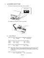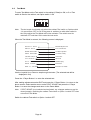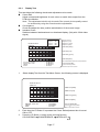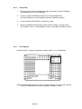
1
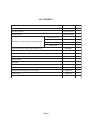
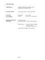
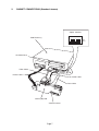
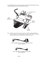
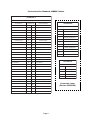
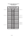
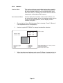
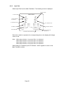
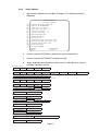
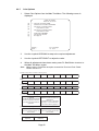
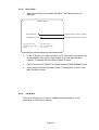
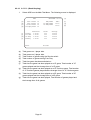
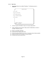
TEKKEN 4 Game PCB Kit Connections and Adjustments Part No 90500133 Issue 2 Page 2 NOTICE is a term to describe a copyright protection technology created by Sony Group. This mark does not necessarily guarantee compatibily with other products bearing the “MagicGate” trademark. is a trademark of Sony Corporation. est une terme décrivant une technique de protection de copyright ne garantit pas nécessairement de crééé par Sony Group. cpmpatabilté avec d’autres produits portant la marque de commerce “MagicGate” est une marque de commerce de Sony Corporation. The DVD-ROM DISC supplied with the product must not be copied, modified, distributed, or used for the purposes other than the operation of the product. Copyright laws protect the contents of the DVD-ROM DISC. Infringement of copyright laws may be subject to criminal penalties. Do not use the supplied DVD-ROM DISC with other product models or other media formats. Doing so may result in equipment failure. Page 3 Contents KIT CONTENTS .............................................................................................................. 5 1. SPECIFICATIONS .................................................................................................... 7 2. CABINET CONNECTIONS (Standard Jamma) ........................................................ 7 3. CABINET CONNECTIONS (JVS Standard) ........................................................... 11 4. FITTING THE DONGLE ......................................................................................... 12 5. FITTING THE CD-ROM DISC ................................................................................ 13 6. ADJUSTMENTS AND SETTINGS ......................................................................... 15 6-1 Option Switches ............................................................................................. 15 6-2 Test Mode ...................................................................................................... 16 6-2-1 Display Test .............................................................................................. 16 6-2-2 Colour Edit ............................................................................................... 18 6-2-3 Convergence ............................................................................................ 18 6-2-4 Interlace ................................................................................................... 19 6-2-5 Input Test ................................................................................................. 20 6-2-6 Game Options .......................................................................................... 21 6-2-7 Coin Options ............................................................................................ 22 6-2-8 Sound Test ............................................................................................... 23 6-2-9 JVS Status ............................................................................................... 23 6-2-10 A. D. S - (Book Keeping) .......................................................................... 24 6-2-11 Data Clear ................................................................................................ 25 Page 4 KIT CONTENTS Description Part No Quantity XTEK4-PCB 1 DVD Rom CD Disc XTEK4-CDROM 1 Jamma (B) PCB XTEK4-JAMMA 1 Tekken 4 PCB Rack Assy Rack Assy to Jamma (B) PCB connecting cables Power Supply Loom 1 RGB Video Loom 1 RCA (Phono) Audio Loom 1 Data Loom 1 Amp EI connectors to 48way Edge Adaptor Loom 69200067 1 Amp EI connectors with Flying Leads Loom 69200066 1 Button Decals 1 set Instruction Card 1 Move List Card 1 Title Board 1 Tekken 4 Promotional Poster 1 Top Flash 40000703 1 Universal Cabinet Side Decal - LHS / RHS 40000704 2 Header Decal 40000705 1 Connection and Adjustment Manual 90500133 1 Page 5 1. SPECIFICATIONS COMPATIBILITY: JAMMA STANDARD (with JAMMA (B) PCB) JAMMA VIDEO STANDARD (JVS) PCB INPUT POWER: +5v (±5%) @ 7A (Min), +12v (±5%) @ 2A (Min) OPERATING ENVIRONMENT: Temperature Humidity MONITOR ORIENTATION AND SIGNAL: Horizontal Orientation Horizontal Frequency 15kHz / 31kHz (selectable) RGB output level +5ºC to +45ºC 10% to 85% (no condensation) 0.7V p-p / 3.0V p-p (selectable) when set to 15kHz 0.7V p-p when set to 31kHz Composite Sync / Separate Sync (selectable) Page 6 2. CABINET CONNECTIONS (Standard Jamma) Option Switches 1 2 3 NO PCB Rack Assy 4 ON OFF CD-ROM Drive Video Cable Power Cable Audio Cable Data Cable Jamma (B) PCB Volume Control Page 7 The JAMMA (B) PCB is connected to the game cabinet with a 56way Edge Connector (standard JAMMA) and 4 and 10way AMP EI Connectors. JAMMA (B) PCB JAMMA 56way Connector 10way AMP EI Connector 4way AMP EI Connector Note: Supplied in the Kit is an Amp EI connectors to 48way extender card adaptor loom, for cabinets with an existing 48way connector, and an AMP EI connectors with flying leads loom for cabinets without a 48way connection. 4 and 10way AMP EI Connector with 48way Extender Card Part No. 69200067 4 and 10way AMP EI Connector with flying leads Part No.69200066 Page 8 Connections for Standard JAMMA Cabinet TEKKEN 4 JAMMA 56way Edge Connector S ol der S i de Terminal No Component Side TEKKEN 4 GND A 1 GND GND B 2 GND +5volt C 3 +5volt +5volt D 4 +5volt E 5 +12volt F 6 +12volt Polarizing Key G 7 Polarizing Key H 8 J 9 L Speaker (-) K 10 L Speaker (+) 7 P1 KICK (Right) Sw5 Audio (-) (mono) L 11 Audio (+) (mono) 8 P1 KICK (Left) Sw4 Video GREEN M 12 V i deo R E D 9 V i deo S Y N C N 13 V i deo B LU E 10 SERVICE P 14 Video GND R 15 TE S T Coin Switch 2 S 16 Coin Switch 1 P2 START T 17 P1 START P 2 L e ve r U P U 18 P 1 L e ve r U P P2 Lever DOWN V 19 P1 Lever DOWN 1 P 2 L e ve r L E F T W 20 P 1 L e ve r L E F T 2 P2 Lever RIGHT Y 21 P1 Lever RIGHT 3 R Speaker (+) P2 PUNCH (Left) Sw1 Z 22 P1 PUNCH (Left) Sw1 4 R Speaker (-) P2 PUNCH (Right) Sw2 a 23 P1 PUNCH (Right) Sw2 P 2 S w 3 N o t u se d b 24 P 1 S w 3 N o t U se d c 25 d 26 GND e 27 GND GND f 28 GND Coin Counter 2 10way AMP EI Connector Pi n N o 1 Description GND 2 Coin Counter 1 3 P2 KICK (Right) Sw5 4 P2 KICK (Left) Sw4 5 6 GND T EK K EN 4 4way A MP EI C onnector Pin No Page 9 Descri ption Connector Loom (Part no 69200066) Adaptor for Earlier Tekken Series Cabinets with 48way Edge Connector (Part No 69200067) PREVIOUS TEKKEN GAMES 48way Extension Connector Solder Side 4w AMP EI pin 4 Terminal No R Speaker (-) Polarizing Key 10w AMP EI pin 4 10w AMP EI pin 8 P2 KICK (Left) Sw4 P1 KICK (Left) Sw4 A24 B24 A23 B23 A22 B22 A21 B21 A20 B20 A19 B19 A18 B18 A17 B17 A16 B16 A15 Component Side R Speaker (+) 4w AMP EI pin 3 Polarizing Key P2 KICK (Right) Sw5 10w AMP EI pin 3 B15 GND 10w AMP EI pin 10 A14 B14 GND 10w AMP EI pin 10 A13 B13 A12 B12 A11 B11 A10 B10 A9 B9 A8 B8 GND 10w AMP EI pin 1 A7 B7 GND 10w AMP EI pin 1 A6 B6 P1 KICK (Right) Sw5 10w AMP EI pin 7 A5 B5 A4 B4 A3 B3 A2 B2 A1 B1 Page 10 3. CABINET CONNECTIONS (JVS Standard) JVS Power Supply Adaptor Video Connector Audio Connectors Data I/O Connector Page 11 4. FITTING THE DONGLE The dongle included in this kit is limited to this game only. DO NOT insert this Dongle in other games. Inserting the Dongle in other games may cause damage. Ensure that the power is switched OFF before inserting the Dongle. 1. Remove 1off pozi head screw (M3x10) and remove the Dongle Cover. Dongle cover Pozi head screw (M3x10) 2. Fit the Dongle to the left hand connector. Left connector Dongle 3. Refit the Dongle cover and pozi head screw (M3x10) Page 12 5. FITTING THE CD-ROM DISC n The CD-ROM Disc must be inserted with the power switched on. To prevent an electric shock, accident or injury, do not touch any parts other than those specified below. n n The supplied CD-ROM Disc is designed exclusively for this product. Never use the CD-ROM Disc in any other product. Do not insert other CD-ROM Discs in the CD-ROM drive of this game. The CD-ROM tray retracts automatically after 10 seconds. 1. Press the eject button of the CD-ROM drive to open the tray. CD-ROM Drive Access Lamp Eject Button Page 13 2. Place the CD-ROM Disc on to the tray, ensuring that the label side (printed surface) is facing away from the Tray. CD-ROM DISC Ensure that the CD-ROM Disc is securely placed on the tray, with the label side facing away from the tray Tray 3. Press the Eject button to retract the Tray in to the unit. 4. Switch the power OFF, wait approx 10 seconds then switch the game back ON. Page 14 ADJUSTMENTS AND SETTINGS The Game PC Board Assy is fitted with 4 Option Switches. Option Switches 2 3 NO 1 4 6. ON OFF The JAMMA (B) PCB has the Volume Control fitted. JAMMA (B) PCB Volume Control 6-1 Option Switches Switch 1 is used to change between Test Mode and Game Mode. ON: Test Mode OFF: Game Mode Switch 2 is used to set the output level of the video signal. 31kHz ON: 0.7V p-p OFF: 0.7V p-p 15kHz ON: 3.0V p-p OFF: 0.7v P-P Switch 3 is used to change the monitor Sync Frequency ON: 31kHz OFF: 15kHz Note: When using a 31kHz monitor, set the RGB input of the monitor to 0.7v. If the monitor does not have a setting adjustment, refer to page 17 section 6-2-1 Display Test, and change the Contrast and RGB Brightness levels to adjust the brightness. Switch 4 is used to set the Video Sync Signal ON: Composite Sync OFF: Page 15 Seperate Sync Test Mode To enter Test Mode set the Test switch in the cabinet (if fitted) to ON, or if no Test switch is fitted to the cabinet, set Option switch 1 ON 2 3 NO 1 4 6-2 Note: The test mode is activated only when the cabinet Test switch or Option switch 1 is moved from OFF to ON. If the game is switched on with either switch in the ON position the Test Mode will not be activated. The switch must be switched OFF and then ON to enter the test mode. When the Test Mode is entered, the following screen is displayed. D IS P L A Y T E S T Monitor Adjustments IN P U T T E S T Tests all switches G A M E O P T IO N S Set Game options C O IN O P T IO N S Set Price of Play SOUND TEST Sound test JVS STATUS Not used A .D .S . Bookkeeping DATA CLEAR Data clear E X IT & S A V E Exit from test mode Use the Joystick Up or Down to step through the tests. (The selected test will be displayed in red) Press the 1 Player Button 1 to enter the selected test. After making adjustments select EXIT and press the 1 Player Button 1 to return to the above screen. Select another test or select EXIT & SAVE and press the 1 Player Button 1 to save the changes and return to the Game Mode. Note: If EXIT &SAVE is not selected and activated, any changes made may not be stored properly. Switching the cabinet Test switch or Option 1 switch OFF does not exit the Test Mode. Switch the cabinet Test switch or Option 1 switch OFF. Page 16 6-2-1 Display Test This test allows the following checks and adjustments to be made. n Colour Edit Adjust contrast and brightness of each colour to match video output from the PCB to the Monitor. Note: This adjustment should only be made if the correct picture quality cannot be achieved by using the normal monitor adjustments. n Convergence Check and adjust the size, position and distortion of the screen image. n Interlace Check Switches between interlaced and non-interlaced display. (Only with 15kHz video signal). Contrast Bright R Bright G Bright B DISPLAY TEST Color bar : : : : OO OO OO OO Overall contrast Brightness (red) Brightness (green) Brightness (blue) Color bar (white) Color bar (red) Color bar (green) Color bar (blue) Previous Color EXIT color edit NEXT EXIT 1. : : : : P1-Button4 P1-Button3 P1-Button1 P1-Start Reset Colour Edit values to factory defaults Colour Edit ON /OFF Select next test pattern Return to test menu screen Select display Test from the Test Menu Screen, the following screen is displayed. DISPLAY TEST Color bar Color bar (white) Color bar (red) Color bar (green) Color bar (blue) ENTER color edit NEXT EXIT 2. 3. : : : P1-Button3 P1-Button1 P1-Start Colour Edit ON /OFF Select to next test pattern Return test menu screen Each time the 1P Button 3 is pressed the Colour Edit adjustment box is turned ON or OFF. Press the 1P Button 1 to step to the next test function COLOUR BAR CONVERGENCE INTERLACE Page 17 6-2-2 Colour Edit 1 Ensure that the Colour Edit Adjustment Box is showing. (Press P1 Button 3 if the Adjustment box is not displayed. 2. Use the Joystick UP/DOWN to step to the required adjustment. (Contrast, Brightness (red), Brightness (green), Brightness (blue)). 3. Use the Joystick LEFT/RIGHT to adjust the value. 3. When all adjustments have been made, press P1 Button 1 to step to the Convergence Test or P1 Start Button to return to the Main Test Menu screen 6-2-3 Convergence Use this screen to adjust the geometry (height, width , etc.) of the Monitor. D I S P L AY T E S T Convergence Previous Color EXIT color edit NEXT EXIT Interlace Contrast Bright R Bright G Bright B : : : : : : : : 150 100 100 100 P1-Button4 P1-Button3 P1-Button1 P1-Start When all adjustments have been made, press P1 Button 1 to step to the Interlace Test or P1 Start Button to return to the Main Test Menu screen. Page 18 6-2-4 Interlace Interlace Mode: This mode provides a more detailed and smoother graphics than the non-interlaced mode. This is achieved by shifting the picture display a half line in the vertical direction every other frame scan, so doubling the vertical resolution without changing the horizontal/vertical frequency. Non-Interlaced Mode: Use this display if the interlace mode results in flicker over the entire screen display. In the non-interlaced mode, there is no shift of the display position, and the display remains constant every time. 1 Ensure that the Colour Edit Adjustment Box is showing. (Press P1 Button 3 if the Adjustment box is not displayed.) 2. Use the Joystick LEFT/RIGHT to change Interlace/Non Interlace. > Interlace Contrast : Bright R : Bright G : Bright B : DISPLAY TEST Interlace check P r ev i o u s C o l o r EXIT color edit NEXT EXIT 3. : : : : 150 100 100 100 P1-Button4 P1-Button3 P1-Button1 P1-Start Interlace mode Reset Colour Edit values to factory defaults Colour Edit ON /OFF Select next test pattern Return to test menu screen When the adjustment has been made, press P1 Button 1 to step back to the Colour Edit Test or P1 Start Button to return to the Main Test Menu screen. Page 19 6-2-5 Input Test Select Input Test from the Main Test Menu. The following screen is displayed. P2 Start switch INPUT TEST P1 Start switch Service switch on the cabinet P1 8-direction lever 1P Start Service Up Down Left Right Shot 1 Shot 3 Shot 5 P1 Button switches DIP switches 2P Start Service Up Down Left Right Shot 2 Shot 4 Shot 6 DIPsw 1 : OFF COIN1: 0 0 0 EXIT : 2 : OFF Shot 1 Shot 3 Shot 5 Shot 2 Shot 4 Shot 6 3 : OFF 4 : OFF COIN2: 0 0 0 P1-Button1&2 To return to test menu screen P2 8-direction lever P2 Button switches Coin signal count (Default: 0) Each time a switch is operated, the corresponding item on the display will change colour to red. Note: When player button 1 is pressed Shot 1 is indicated. When player button 2 is pressed Shot 2 is indicated When player button 3 is pressed Shot 4 is indicated When player button 4 is pressed Shot 5 is indicated When testing is completed, press P1 Buttons 1 and 2 together to return to the Main Test Menu screen. Page 20 6-2-6 Game Options 1. Select Game Options from the Main Test Menu. The following screen is displayed. GAME OPTIONS < Defaults in Green > (a) (b) (c) (d) (e) (f) (g) (h) (i) (j) (k) (l) (m) (n) Subtitles language: ENGLISH Difficulty level: MEDIUM Fight count <1P game> : 2 Fight count <VS game> : 2 Life bar <1P game> : +1 Life bar <VS game> : +1 Guard damage: OFF Neutral guard: ON Round time: 60 Character change at continue: YES Character change at VS game: YES Sound in attract mode: YES Event mode: OFF Hit color: GREEN Modify : P1-Left/Right EXIT : P1-Start 2. Use the Joystick UP/DOWN to step to the required adjustment. 3. Use the Joystick LEFT/RIGHT to adjust the value. 4. When all adjustments have been made, press P1 Start Button to return to the Main Test Menu screen (a) Subtitles Language ENGLISH FR E N C H SPANISH GERMAN ITALIAN VERY HARD ULTRA HARD (b) Difficulty level (degree of game difficulty) EASY MEDIUM H AR D ULTRA HARD 1 ULTRA HARD 2 (c) Fight Count <1P game > (number of rounds required to win the game in 1 player mode) 1 2 3 4 5 (d)) Fight Count <VS game > (number of rounds required to win the game in 2 player mode) 1 2 3 4 5 (e) Life bar <1P game > (energy guage in 1 player mode) -2 -1 NORMAL +1 +2 (f) Life bar < VZ game > (energy guage in 2 player mode) -2 -1 NORMAL +1 +2 (g) Guard damage (damage received on guard) ON (slight damage) OFF (no damage) (h) Neutral guard ( guard activated with lever in neutral) ON OFF (i) Round time (time [seconds] per round) 30 40 60 80 99 (j) Character change at continue (change of character for continued game) YES (possible) NO (not possible) (k) Character change at VS game (change of character YES (possible) NO (not possible) (l) Sound in attract mode YES (with sound) NO (without sound) (m) Event mode (action after 2 player game has finished) ON (game over for both players) OFF (1P game play continues for winner) (n) Hit colour (colour of graphic effects when attacks are successful R ED GREEN Page 21 SU PER H AR D E X TR A S U P E R H A R D 6-2-7 1. Coin Options Select Coin Options from the Main Test Menu. The following screen is displayed. COIN OPTIONS Defaults in Green > Start Cost 1Credit to START Continue Cost 1Credit to CONTINUE Coin chute 1 mechanical value 1Coin count as 1coin Coin chute 2 mechanical value 1Coin count as 1coin Credit mode COMMON Coin counter 1counter Free play no (a) (b) (c) (d) (e) (f) (g) M odif y : EXI T : P1-Left/Right P1-Start 2. Use the Joystick UP/DOWN to step to the required adjustment. 3. Use the Joystick LEFT/RIGHT to adjust the value. 4. When all adjustments have been made, press P1 Start Button to return to the Main Test Menu screen Note: When using a CashFlow acceptor ensure that Cost and Coin Chute values are set to 1 (a) Star t cost (number of credits to star t a game) 1 2 3 4 5 6 7 8 9 (b) Continue cost (number of credits to continue a game - must be equal to or smaller than star t cost) 1 2 3 4 5 6 7 8 9 7 8 9 7 8 9 (c) Coin chute 1 mechanical value (number of credits for each coin) 1 2 3 4 5 6 (d) Coin chute 2 mechanical value (number of credits for each coin) 1 2 3 4 5 6 (e) Credit Mode (credit storage and use) COMMON Credits are stored as a single account regardles of which coin switch or star t switch is operated. EACH ONE Different credit accounts are established. Credits from coin 1 are used by player 1 and credits from coin 2 are used by player 2 (f) Coin counter (assignment of coin meters) 1 COUNTER Both coin switches share one coin counter 2 COUNTERS Each coin switch has its own coin counter (g) Free play YES (no coins required) NO (coins required) Page 22 6-2-8 Sound Test 1. Select Sound Test from the Main Test Menu. The following screen is displayed. SOUND TEST POSITION:off Displays which speaker is playing SPEAKER:stereo Displays monaural/stereo setting Check Sound Change Speaker EXIT : P1-Button1 : P1-Left/Right : P1-Start 2. Press 1P Button 1 to conduct a stereo check. Sound will be produced from the left speaker only, then the right speaker only, then both speakers together. The display will show which speaker is active. 3. Use the Joystick LEFT/RIGHT to change between STEREO/MONO sound. 4. When testing has been completed, press P1 Start Button to return to the Main Test Menu screen 6-2-9 JVS Status This test is inactive and not used on JAMMA system cabinets, it is only operational on JVS system cabinets. Page 23 6-2-10 A. D. S - (Book Keeping) 1. Select ADS from the Main Test Menu. The following screen is displayed. ADS ON TIME x:xx:xx xx xx xx xx (a) (b) (c) (d) Coin 1 Coin 2 Service Freeplay Total Total Total Total (i) (j) (k) (l) 1P 1P VS All Total Time x:xx:xx x:xx:xx x:xx:xx x:xx:xx Play Cont. Play Play EXIT : Play Ratio 1P Play Ratio VS Play Ratio Count xxx xxx xxx xxx 100% xx.x% xx.x% (e) (f) (g) (h) Average x:xx:xx x:xx:xx x:xx:xx x:xx:xx P1-Start (a) Total games on 1 player side. (b) (c) Total games on 2 player side. Total number of games using the Service switch. (d) (e) Total number of games during Free Play. Total time game has been switched on. (f) Total time the game has been played as a 1P game, Total number of 1P games played and the Average time of a 1P game. (g) Total time the game has been played as a 1P Continue game, Total number of 1P Continue games played and the Average time of a 1P Continue game. (h) Total time the game has been played as a 2P game, Total number of 2P games played and the Average time of a 2P game (g) Total time the game has been played, Total number of games played and the Average time of all games. Page 24 6-2-11 1. Data Clear Select Data Clear from the Main Test Menu. The following screen is displayed. DATA CLEAR (a) Cancel (b) A.D.S. data clear (c) Ranking data clear (d) Set defaults all options (e) All clear CLEAR: P1-Button1 EXIT : P1-Start 2. Use the Joystick UP/DOWN to step to the required adjustment. 3. When all adjustments have been made, press P1 Start Button to return to the Main Test Menu screen (a) Returns to the Main Test Menu. (b) (c) Resets all Book Keeping data to zero Resets all ranking data such as record of consecutive wins to factory default (d) (e) Resets all Game and Coin Options to factory default. Executes (a), (b) and (c) all at once. Page 25 Copies of Namco Game Manuals can be downloaded from our website: www.namco.co.uk They are located under Components Distribution For all Parts or Technical Support contact: Brent Electronic, Namco House, Units 5-8, Acton Park Estate, The Vale, London. W3 7QE www.namco.co.uk For Technical Support, Warranty and Advance Replacement Parts:- +44 (0) 20 8324 6120 For Consumable Parts:- +44 (0) 20 8324 6102 Fax for both:- +44 (0) 20 8324 6126