1
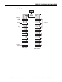
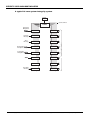
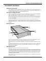
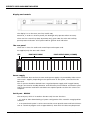
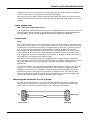
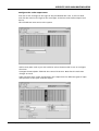
INTEGRITY
VOICE ALARM
ROUTING MATRIX
Installation and
Maintenance Manual
Approved Document No. DCS0003214 Rev 0 (8/2/05)
INTEGRITY VOICE ALARM ROUTING MATRIX
CONTENTS
IMPORTANT NOTES . . . . . . . . . . . . . . . . . . . . . . . . . . . . . . . . . . . . . . . . . . . . . . . . . . . .3
Items supplied . . . . . . . . . . . . . . . . . . . . . . . . . . . . . . . . . . . . . . . . . . . . . . . . . . . . . . . . 3
System design . . . . . . . . . . . . . . . . . . . . . . . . . . . . . . . . . . . . . . . . . . . . . . . . . . . . . . . . .3
Equipment guarantee . . . . . . . . . . . . . . . . . . . . . . . . . . . . . . . . . . . . . . . . . . . . . . . . . .3
BASIC OVERVIEW AND KEY FEATURES . . . . . . . . . . . . . . . . . . . . . . . . . . . . . . . . . . . . .4
Integrity Schematic Template . . . . . . . . . . . . . . . . . . . . . . . . . . . . . . . . . . . . . . . . . . . .4
A basic Integrity system with six zones . . . . . . . . . . . . . . . . . . . . . . . . . . . . . . . . . . . .5
A 16 zone system with four paging consoles . . . . . . . . . . . . . . . . . . . . . . . . . . . . . . .6
A 64 zone system with separate message stores . . . . . . . . . . . . . . . . . . . . . . . . . . . . .7
A 58 zone system with synchronized messages . . . . . . . . . . . . . . . . . . . . . . . . . . . . . .8
THE INTEGRITY MAINFRAME . . . . . . . . . . . . . . . . . . . . . . . . . . . . . . . . . . . . . . . . . . . . .9
Mechanical construction . . . . . . . . . . . . . . . . . . . . . . . . . . . . . . . . . . . . . . . . . . . . . . . .9
Anti-Static handling guidelines . . . . . . . . . . . . . . . . . . . . . . . . . . . . . . . . . . . . . . . . . . .9
Opening the case . . . . . . . . . . . . . . . . . . . . . . . . . . . . . . . . . . . . . . . . . . . . . . . . . . . . . .9
Removing the cover . . . . . . . . . . . . . . . . . . . . . . . . . . . . . . . . . . . . . . . . . . . . . . . . . . . .9
Display and controls . . . . . . . . . . . . . . . . . . . . . . . . . . . . . . . . . . . . . . . . . . . . . . . . . . .10
The rear panel . . . . . . . . . . . . . . . . . . . . . . . . . . . . . . . . . . . . . . . . . . . . . . . . . . . . . . .10
Power supply . . . . . . . . . . . . . . . . . . . . . . . . . . . . . . . . . . . . . . . . . . . . . . . . . . . . . . . .10
Serial port RS232C . . . . . . . . . . . . . . . . . . . . . . . . . . . . . . . . . . . . . . . . . . . . . . . . . . . .10
Internal layout . . . . . . . . . . . . . . . . . . . . . . . . . . . . . . . . . . . . . . . . . . . . . . . . . . . . . . .11
INTEGRITY COMPONENTS
CPU central processor unit card . . . . . . . . . . . . . . . . . . . . . . . . . . . . . . . . . . . . . . . . .12
GPI general purpose interface card . . . . . . . . . . . . . . . . . . . . . . . . . . . . . . . . . . . . . .12
1LS single group life-safety card . . . . . . . . . . . . . . . . . . . . . . . . . . . . . . . . . . . . . . . . .12
SVM sound vault module . . . . . . . . . . . . . . . . . . . . . . . . . . . . . . . . . . . . . . . . . . . . . .12
BGM background music input card . . . . . . . . . . . . . . . . . . . . . . . . . . . . . . . . . . . . . .12
OP2 two zone audio output card . . . . . . . . . . . . . . . . . . . . . . . . . . . . . . . . . . . . . . . .13
CI-16 control card . . . . . . . . . . . . . . . . . . . . . . . . . . . . . . . . . . . . . . . . . . . . . . . . . . . . .13
CONNECTING THE MAIN FRAME TO A PC . . . . . . . . . . . . . . . . . . . . . . . . . . . . . . . . .13
INTEGRITY MAINFRAME MENU STRUCTURE . . . . . . . . . . . . . . . . . . . . . . . . . . . . . . .14
FAULT MONITORING . . . . . . . . . . . . . . . . . . . . . . . . . . . . . . . . . . . . . . . . . . . . . . . . . .14
CONFIGURATION - THE INTEGRITY EDITOR . . . . . . . . . . . . . . . . . . . . . . . . . . . . . . . .15
Installing Integrity Editor . . . . . . . . . . . . . . . . . . . . . . . . . . . . . . . . . . . . . . . . . . . . . .15
Overview . . . . . . . . . . . . . . . . . . . . . . . . . . . . . . . . . . . . . . . . . . . . . . . . . . . . . . . . . . . .15
Page tabs . . . . . . . . . . . . . . . . . . . . . . . . . . . . . . . . . . . . . . . . . . . . . . . . . . . . . . . . . . .15
Configuring the hardware . . . . . . . . . . . . . . . . . . . . . . . . . . . . . . . . . . . . . . . . . . . . .16
FAULT LOGGING . . . . . . . . . . . . . . . . . . . . . . . . . . . . . . . . . . . . . . . . . . . . . . . . . . . . . 24
DIMENSIONS, POWER REQUIREMENTS & CURRENT CONSUMPTION . . . . . . . . . . . .27
© 2005. Errors and omissions excepted.
The Manufacturer of this product operates a policy of continuous improvement and reserves the right to alter product
specifications at its discretion and without prior notice. All of the instructions covered in this manual have been carefully
checked prior to publication. However, no responsibility can be accepted by the Manufacturer for any inaccuracies or for
any misinterpretation of an instruction or guidance note.
Integrity Voice Alarm Routing Matrix Installation & Maintenance Manual • Approved Doc. No. DCS0003214 Rev 0 (8/2/05) • Page 2
INTEGRITY VOICE ALARM ROUTING MATRIX
IMPORTANT NOTES
This equipment must only be installed and maintained by a suitably skilled
and technically competent person.
This equipment is a piece of Class 1 equipment and MUST BE EARTHED.
Items supplied with this routing matrix
• Installation & maintenance manual (i.e. this manual)
This explains how to install, commission and maintain the voice alarm routing matrix
• User manual/log book
This gives detailed operational information, some of which will need to be
referenced by the installation engineer when setting up the matrix. Sections of this
manual must be completed by the engineer prior to system handover.
• Accessory pack
Containing 1 x 4 way ‘Weidmüller BL5.08/4’ power connector and 1 x Integrity Editor
English Language configuration CD
System design
Voice alarm system design is beyond the scope of this document. A basic understanding
of general fire alarm and voice alarm system components and their use is assumed.
We strongly recommend that a suitably qualified and competent person is consulted in
connection with the design and specification of the voice alarm system and that the system is commissioned and serviced in accordance with the specification and national standards. The fire officer (Authority Having Jurisdiction) concerned with the property should
be contacted at an early stage in case he has any particular requirements.
For UK applications we recommend that you read BS 5839 : Part 8 : 1988 (Voice Alarm
Systems) and BS 5839 : Part 1 2002 (Fire detection and fire alarm systems for buildings –
code of practice for system design, installation, commissioning and maintenance) available from your local reference library or from the British Standards Institute, Customer
Services Department, 389 Chiswick High Road, London, W4 4AL. Tel +44 (0)20 8996 9000
Web: www.bsi-global.com. It should be noted that the above documents can be subject
to revision or update at any time and we recommend you check the status of them with
the British Standards Institute before ordering. For most of the rest of Europe, we recommend that you read IEC EN 60849 (Sound systems for emergency purposes). Other
national standards of installation should be referenced and adhered to where relevant.
No responsibility can be accepted by the manufacturer or distributors of this equipment
for any misinterpretation of an instruction or guidance note or for compliance of the system as a whole.
This voice alarm routing matrix MUST be installed and maintained by a suitably skilled
and technically competent person.
This voice alarm routing matrix is not designed to be installed in hazardous areas.
This document must not be left accessible to the user.
Equipment guarantee
This equipment is not guaranteed unless the complete system is installed and
commissioned in accordance with national standards by an approved and competent person or organization. This product has been manufactured in conformance with
the requirements of all applicable EU Council Directives. This product has been manufactured in conformance with the requirements of all applicable EU Council Directives.
Integrity Voice Alarm Routing Matrix Installation & Maintenance Manual • Approved Doc. No. DCS0003214 Rev 0 (8/2/05) • Page 3
INTEGRITY VOICE ALARM ROUTING MATRIX
BASIC OVERVIEW AND KEY FEATURES
The Integrity Mainframe is an eight channel audio and control routing matrix that allows
the construction of voice alarm systems that comply with the requirements of the following
standards:
• BS 5839 part 8, 1998 : Voice Alarm Systems. Fire detection and alarm systems for buildings.
Part 8. Code of practice for the design, installation and servicing of voice alarm systems.
• EN 60849 : Sound systems for emergency purposes : 1998
Its modular design allows systems to be constructed with up to 16 audio zones and up to
eight audio input channels.
Up to four Integrity systems can be linked to one or more paging consoles so that systems
with up to 64 audio zones can be constructed. However, the systems are still separate from
each other and, apart from the paging console microphone, audio does not pass between
them.
Integrity schematic template
PSE
1
9
2
10
3
11
4
12
5
13
6
14
7
15
8
16
Audio Inputs
Audio Outputs
To amplifiers and loudspeakers
8 audio channels
CPU
Integrity Voice Alarm Routing Matrix Installation & Maintenance Manual • Approved Doc. No. DCS0003214 Rev 0 (8/2/05) • Page 4
INTEGRITY VOICE ALARM ROUTING MATRIX
A basic Integrity system with six zones
PSE
8 audio channels
CPU
Emergency
Microphone
ILS
OP2
Evacuate
Message
SVM
OP2
Alert
Message
SVM
OP2
4
12
5
13
6
14
7
15
C1-6
16
Audio Inputs
Audio Outputs
Fire Alarm
Interface
To amplifiers
and loudspeakers
Integrity Voice Alarm Routing Matrix Installation & Maintenance Manual • Approved Doc. No. DCS0003214 Rev 0 (8/2/05) • Page 5
INTEGRITY VOICE ALARM ROUTING MATRIX
A typical 16 zone system Intergrity system
PSE
8 audio channels
CPU
ILS
OP2
Evacuate
Message
SVM
OP2
Alert
Message
SVM
OP2
Zonal paging
microphone
GPI
Local paging
microphone
ILS
OP2
BGM
OP2
Music
source
OP2
To amplifiers and loudspeakers
Emergency
Microphone
OP2
Fire Alarm
Interface
CPI
OP2
Audio Inputs
Audio Outputs
Integrity Voice Alarm Routing Matrix Installation & Maintenance Manual • Approved Doc. No. DCS0003214 Rev 0 (8/2/05) • Page 6
INTEGRITY VOICE ALARM ROUTING MATRIX
A 64 zone system with separate message stores
As messages are held separately in each rack, synchronisation between messages from different racks is not guaranteed.
PSE
PSE
CPU
CPU
OP2
GPI
OP2
SVM
OP2
SVM
OP2
SVM
OP2
SVM
OP2
OP2
CI-16
OP2
OP2
OP2
OP2
Fire Alarm
Interface
OP2
CI-16
OP2
PSE
PSE
CPU
CPU
GPI
OP2
GPI
OP2
SVM
OP2
SVM
OP2
SVM
OP2
SVM
OP2
OP2
OP2
Fire Alarm
Interface
OP2
CI-16
To amplifiers and loudspeakers
Fire Alarm
Interface
OP2
OP2
OP2
OP2
OP2
OP2
OP2
OP2
Fire Alarm
Interface
CI-16
OP2
Integrity Voice Alarm Routing Matrix Installation & Maintenance Manual • Approved Doc. No. DCS0003214 Rev 0 (8/2/05) • Page 7
To amplifiers and loudspeakers
OP2
To amplifiers and loudspeakers
GPI
To amplifiers and loudspeakers
Zonal
Emergency
Microphone
INTEGRITY VOICE ALARM ROUTING MATRIX
A 58 zone system with a zonal emergency
paging console and synchronised messages
PSE
PSE
CPU
CPU
OP2
GPI
OP2
SVM
OP2
ILS
OP2
SVM
OP2
ILS
OP2
OP2
CI-16
OP2
OP2
OP2
OP2
Fire Alarm
Interface
OP2
CI-16
OP2
PSE
PSE
CPU
CPU
GPI
OP2
GPI
OP2
ILS
OP2
ILS
OP2
ILS
OP2
ILS
OP2
OP2
OP2
Fire Alarm
Interface
OP2
CI-16
To amplifiers and loudspeakers
Fire Alarm
Interface
OP2
OP2
OP2
OP2
OP2
OP2
OP2
OP2
Fire Alarm
Interface
CI-16
OP2
Integrity Voice Alarm Routing Matrix Installation & Maintenance Manual • Approved Doc. No. DCS0003214 Rev 0 (8/2/05) • Page 8
To amplifiers and loudspeakers
OP2
To amplifiers and loudspeakers
GPI
To amplifiers and loudspeakers
Zonal
Emergency
Microphone
INTEGRITY VOICE ALARM ROUTING MATRIX
THE INTEGRITY MAINFRAME
Mechanical construction
The Integrity mainframe comprises a 2U (3.5 inch, 88.9mm) high chassis designed to fit a
standard 19 inch rack system. In order to install the necessary input and output cards, it is
necessary to disassemble and then reassemble the case.
Anti-static handling guidelines
Please ensure that the following electro-static handling precautions are taken immediately
prior to handling panels, PCBs or any other static-sensitive components:Before handling any static-sensitive items, operators should rid themselves of any personal
electro-static charge by momentarily touching any sound connection to a safety-earth,
e.g. heating radiator.
Always handle PCBs by their sides and avoid touching the legs of any components.
PCBs should be stored in a clean, dry place which is free from vibration, dust and excessive
heat. Retaining PCBs in a suitable cardboard box will also guard them against mechanical
damage.
Opening the case
Top
front
rail
Top
rear
rail
Top
front
screw
Top
rear
screw
On each side of the case there are four cross-head screws. Using a Pozidriv No 1 screwdriver, loosen the two front top screws and remove the rear top screws.
Identify the top rear rail and lift it upwards. The steel cover will pull out from the front
rail.
Remove the blanking plates from the rear and plug in the required modules. Replace the
blank plates, making sure that they are seated fully. It may be necessary to ‘jiggle’ the
plates to make them fit.
Replacing the cover
Remove the front top screws and remove the front rail.
Locate the rear rail on top of the back plates and push down to make sure that they are
all seated fully. Replace the top rear screws but do not tighten fully. Push the steel cover
into the slot on the front rail and then locate the cover into the slot in the rear rail. The
front rail will drop into position between the front cheeks. Insert the top front screws
and tighten up, but not fully.
Now tighten all four screws a bit at a time, taking care not to overtighten and strip the
thread in the rails.
Integrity Voice Alarm Routing Matrix Installation & Maintenance Manual • Approved Doc. No. DCS0003214 Rev 0 (8/2/05) • Page 9
INTEGRITY VOICE ALARM ROUTING MATRIX
Display and controls
The display is a 32 character, two line, backlit LCD,
Note that, in order to conserve power, the backlight only operates when necessary.
There are four control keys (NO, UP, DowN, YES), green LEDs for main and auxiliary
power present indication and a yellow LED for general fault indication.
The rear panel
There are 17 ‘slots’ for audio and control input and output cards.
As supplied, only the CPU card is fitted.
CPU
EIGHT INPUT CARDS
EIGHT OUTPUT CARDS (16 ZONES)
Power supply
The mainframe does not have its own mains power supply. It is powered by either one or
two 24 Vd.c. supplies, depending on the specification of the system, connected via the
CPU card.
The d.c. power should be derived from a regulated power supply with integral battery
charger connected to standby batteries. Overall battery size should be calculated as specified in the relevant installation standards. See separate product sections for current consumption.
Serial port - RS232C
The serial port, which is located on the CPU card, has two functions.
• It is used to allow downloading of system configuration files created in Integrity Editor
software.
• In an operational system it can be connected to a PC to provide status and fault information to a terminal program such as HyperTerminal, from which the data may be printed.
Integrity Voice Alarm Routing Matrix Installation & Maintenance Manual • Approved Doc. No. DCS0003214 Rev 0 (8/2/05) • Page 10
INTEGRITY VOICE ALARM ROUTING MATRIX
Internal layout
Behind the front panel are the circuit boards for the controls, LCD and a fault warning
sounder.
In the bottom of the case is a motherboard with 17 sockets for cards.
CPU
Integrity motherboard
CH1 CH2
CH3 CH4
CH5 CH6
CH7
CH8
CH9 CH10 CH11 CH12 CH13 CH14 CH15 CH16
Motherboard
The motherboard carries eight analogue audio channels, one monitoring tone channel, a
data control bus and power distribution.
CPU slot
The left hand slot is marked “CPU Or iNET Card Only”. This slot can only contain a CPU card.
CH1-CH8 slots
These slots take any of the currently supported audio input or control cards.
Slot CH1 has a feature to ensure that failure of any system critical microprocessor results
in the audio input from this slot being routed as top priority all-call to all audio output
zones. Therefore, slot CH1 is normally used for connection of an emergency
microphone(s). Apart from this, any slot can be used for any input or control card as priorities are assigned in the configuration software.
CH9-CH16 slots
These slots take any of the currently supported audio output cards or control cards.
Integrity Voice Alarm Routing Matrix Installation & Maintenance Manual • Approved Doc. No. DCS0003214 Rev 0 (8/2/05) • Page 11
INTEGRITY VOICE ALARM ROUTING MATRIX
INTEGRITY COMPONENTS
CPU - Central processor unit card
This card is the heart of the system. It receives the d.c. power, it has a serial port for programming and fault reporting and it controls and monitors all the other cards; it drives
the display, responds to the front panel controls and logs the faults. See page 23 (Fault
Logging) and page 13 (Connecting the mainframe to a PC or printer).
Audio input cards
All audio inputs must be ‘line’ level (0 dB, 775mV) and so ordinary microphones cannot be
directly attached to Integrity. However, all SigNET microphones and paging consoles contain pre-amplifiers. This helps avoid interference on the long microphone runs (1kM or so)
that are often required in large buildings.
GPI – General purpose interface card
This card has three RJ45 Category 5 sockets and is used to connect to desk or wall-mounted paging consoles which can be configured for emergency or normal use as follows:
Each main button can have paging access to any combination of audio zones or to select
and route messages or music sources.
LEDs associated with main buttons can display red when evacuate and yellow when alert
messages are playing.
The LCD can show the same fault and status information as the Mainframe LCD.
All paging consoles connected to a GPI card must be of exactly the same type and the
buttons will operate identically. However, different users can be configured and these can
have different levels of access to the controls and indicators. If different functionality is
required, the paging consoles must be connected to separate GPI cards. (Note there are
exceptions to these rules but restrictions are too complex to be covered in this manual).
1LS – Single group life-safety input card
This card is normally used to connect to an all-call emergency microphone and to manually trigger the ‘evacuate’ and ‘test’ messages. However, the fault monitoring may be overridden and it may be used for non-emergency microphones or any balanced audio source
which can be routed to any one group of output zones.
It has two connectors, an eight way ‘Weidmüller’ connector and an RJ45 female (Cat 5) connector, which duplicates the Weidmüller connections and is used to simplify rack assembly.
SVM – Sound Vault Module
Available in two variants, 16 kHz sample rate and 11kHz sample rate.
This card comprises a mother board that contains the processor and a daughter board
that stores and monitors the messages.
The 16 kHz daughter board carries a fully monitored message store with enough memory to
hold 32 seconds of high quality recordings (16 bit, 16 kHz). The 11kHz daugher board carries
a fully monitored message store with enough memory to hold 44 seconds of lower quality
recordings (16 bit, 11kHz). There are four message segments, each of eight seconds maximum (16kHz version) or 11 seconds maximum (11 kHz version). Only one message can be
played at a time and, as emergency message recordings also include the pre-announcement
chime and silences, most message stores are only used for one or two recordings.
In the event of a fault in the message store, the mother board will play default alert
tones instead of the message(s).
BGM – Background Music input card
This card is used to connect unbalanced stereo and to select it for routing. It has a pair of
female phono (RCA) connectors, a four gang DIP switch and a six-way ‘Weidmüller’ connector.
Integrity Voice Alarm Routing Matrix Installation & Maintenance Manual • Approved Doc. No. DCS0003214 Rev 0 (8/2/05) • Page 12
INTEGRITY VOICE ALARM ROUTING MATRIX
The DIP switches are used to select the audio input level to suit the outputs of different
classes of audio device and to provide a fixed routing trigger.
The connector has an open collector general fault output and allows up to four remote
unmonitored switches to be used to route the audio to different zones (subject to configuration).
Audio output cards
OP2 – Two zone audio output card
This card provides the connections for two zones on ‘Weidmüller’ connectors. That is, balanced
line level audio, control out/fault in and ground (technical earth) plus a programmable optoisolated output, typically used to trigger an override to third party sound systems.
Control card
CI-16
This card is usually used as a fire alarm interface that causes emergency messages to play,
but can be used to connect any normally-open switches in order to route any audio inputs
to audio zones. It provides sixteen pairs of trigger inputs, a reset pair, a general fault output, an auxiliary fault output and a ground (technical earth). Triggers are normally
derived from fire alarm sounder circuits, which are reverse biased so that they can measure the presence of an end of line device (EOLD). This EOLD is usually connected across
each trigger pair at the rack terminations. In the event of an open or short circuit fault in
the trigger line, the fire panel will report a fault.
In order to ensure that a message, once triggered, does not stop unless it is positively
reset, the inputs will latch on and are only reset when a voltage is applied across the reset
pair. Individual inputs can be configured so that they do not latch if the application
requires this.
In some installations it is not possible to provide sounder outputs, in which case the auxiliary 24 V d.c. can be connected via normally open relay contacts to trigger the inputs.
Compliance with installation standards is usually achieved by installing the relays on a
detection loop that is physically connected to the equipment rack. The detection loop
itself is monitored by the fire detection system. Note that for maximum reliability, loop
isolators should be installed on either side of the relay interface.
Connecting the mainframe to a PC or printer
The lead shown below, which is normally used with SigNET’s LS system, is suitable for
connecting the mainframe to a PC or printer. However, a standard null modem cable,
which does not have the link between pins 7 and 8 may be used instead.
5
5
9
9
4
4
PC
8
8
7
7
6
6
3
3
Mainframe
2
2
1
9-pin female
1
9-pin male
Integrity Voice Alarm Routing Matrix Installation & Maintenance Manual • Approved Doc. No. DCS0003214 Rev 0 (8/2/05) • Page 13
INTEGRITY VOICE ALARM ROUTING MATRIX
Integrity mainframe menu structure
> Idle (shows status and who to ring if there are faults)
> Logging In
> Main Menu
> View/Accept Faults
> Yes/No
> Change Volumes
> Select Output
> Change Volumes
> Change Alarm Tones
> Fault Tones
> Continuous Woop
> Intermittent Woop
> Continuous Tri-Tone
> Intermittent Tri-Tone
> Mute
> Reminder Tones
> Whoop
> Low Tone
> High Tone
> Mute
> Display Options
> Show Healthy if no active faults = ON/OFF
> Eject Fault Report Page
> Change Login
> Change Clock
> Reboot
> Shut Down
> Show Information
Fault monitoring
Up to 99 events of each individual fault can be recorded, although the times are not kept.
The time and date of faults are on the record that is sent out of the serial port on the CPU.
Faults are displayed on the front LCD, and also on any connected paging consoles (provided the display is enabled). A fault buzzer output is initiated. This can have four tones, plus
mute (used during commissioning only). If the fault warning has been silenced, a reminder
beep sounds every five seconds.
At the main panel, when a fault occurs, it can be silenced as follows:
Enter the PIN and press the YES button.
The display will show ‘Enter PIN **** (Default 2222). The first asterisk will be flashing.
Use the UP or DOWN keys to select the first character and press YES.
The second asterisk will now flash. Enter the second, third and fourth characters.
Once the fourth correct number is entered, the display will say ‘View/Accept Faults’
You can now silence the fault buzzer or scroll through the menus.
If you make a mistake, simply press NO to go back to the beginning.
Once you have logged on, you are presented with the option ‘View/Accept Faults’
Press YES and scroll through the faults.
Press YES on any fault, this will accept that fault AND silence the buzzer.
If a fault is still present, it will reset the fault counter for that fault to one, and the fault
will still display.
If the fault is not present, it will reset the fault counter to zero and the fault will not display.
Integrity Voice Alarm Routing Matrix Installation & Maintenance Manual • Approved Doc. No. DCS0003214 Rev 0 (8/2/05) • Page 14
INTEGRITY VOICE ALARM ROUTING MATRIX
CONFIGURATION - INTEGRITY EDITOR
Integrity is configured entirely via an easy to use PC program called Integrity Editor. The only
functions that can be changed without this program are output levels for paging and music
(not emergency messages or announcements), fault reporting/acceptance and local configuration (such as user options on paging panels attached to GPI cards). Integrity Editor enables an
engineer or salesman to design a system on the PC, audition it and to prove that it will work.
Once the hardware is assembled, it can be configured by downloading this program.
Installing Integrity Editor
Integrity Editor is supplied on a CD complete with English language sound files. Simply
insert the CD in your CD drive and follow the on-screen prompts. If the installation
program does not open, go to start/run and type D:\setup.exe and OK (where D is the
letter of your CD drive) to start the InstallShield Wizard.
Overview of Integrity Editor
The following overview is not detailed as this is outside the scope of this document and it
should be noted that some areas may change as the software continues to be developed.
For detailed instructions always refer to the help files provided as part of Integrity Editor.
A thorough knowledge of the Windows operating system and its conventions is assumed.
Open the program. If it does not start immediately, the default location is: C:\Program
Files\SigNET\Integrity\IntegrityEditor.exe. You will be presented with this screen.
Page tabs
There are six visible page tabs, Cause and Effects, Hardware, Options, Simulation, and
Specification and Notes. Another tab, Integrity Config can be brought up by entering the
password (Default 2222) in the Password field.
Hardware
This page is used to enter the hardware and set up the attributes of the audio and control inputs and outputs.
Cause and effects
This page is used to select the priorities each audio input has over other inputs, to associate input controls with them and to select in which output zones they will play.
Integrity Voice Alarm Routing Matrix Installation & Maintenance Manual • Approved Doc. No. DCS0003214 Rev 0 (8/2/05) • Page 15
INTEGRITY VOICE ALARM ROUTING MATRIX
Options
This page is used to select different options that may be required by advanced users.
Normally all the option boxes are selected.
Simulation
This page stores the path to the default sound files, which are in English. If Integrity
Editor has been installed using the InstallShield Wizard, this page is not normally used
except for selecting the path to custom messages such as non-English.
Specification
This page produces a picture of the rear of the mainframe showing the cards that have
been selected for each slot along with text to show how the cards have been customised.
For instance, slot 0, the CPU card will have the Site Description. This page can be printed
out for future reference but it cannot be merged into another program such as Word.
Notes
As is implied by the name, this page allows notes about the system to be recorded for
future reference. It is particularly useful when unusual configurations have been adopted
to solve a problem.
Integrity Config
This page allows the Integrity Editor program to be downloaded to the hardware.
Configuring the hardware
There are no restrictions on the order of configuring hardware, or of making changes to
the configuration. The following sequence is a typical example.
Save the file
Before any programming it is wise to name and save the file. Left click on the File menu,
select Save as, browse to a suitable location and give the file a meaningful name before
saving. The file extension .igy will be added automatically.
Configure the CPU card
Left Click on the CPU card image, which will turn blue. Here you can enter the site name,
choose whether the system will display the maintenance company’s details when a fault
occurs, and select other functions to do with the amplifier monitoring function.
Integrity Voice Alarm Routing Matrix Installation & Maintenance Manual • Approved Doc. No. DCS0003214 Rev 0 (8/2/05) • Page 16
INTEGRITY VOICE ALARM ROUTING MATRIX
Configure the audio output zones
Left click on the rectangle to the right of the pre-labelled OP2 card. It will turn blue.
Left click the arrow to the right of the ‘Card type’ and select ‘Dual Audio Output’ from
the list.
This will add two more zones to the system.
Add as many OP2 cards as you wish and then select the Zone tabs in turn to configure
the zones.
Overtype the Description field with the name of that zone. Note that the Fault Text
changes to match.
Other functions that can be changed here are output levels for different types of input
and operation of the open collector output.
Integrity Voice Alarm Routing Matrix Installation & Maintenance Manual • Approved Doc. No. DCS0003214 Rev 0 (8/2/05) • Page 17
INTEGRITY VOICE ALARM ROUTING MATRIX
Configure the audio inputs
Left click to the right of the CPU and select an audio input card. In order to provide a
fail-safe source in the event of a processor failure, audio inserted via this slot will be routed to all zones. Therefore, this card will normally be used for a life-safety microphone.
For an all-call microphone(s), select the 1LS card. For a zonal mic., select the GPI card.
The 1LS card
Up to four emergency microphones can be connected to a 1LS card using four two-core
or two four-core fire resistant cables wired in ‘daisychain’ format (one after the other).
The default setting on this page is correct for an emergency microphone. However, the
1LS card can be used for any balanced audio input and the details are customised here.
For instance, you can alter the name of the microphone(s), change the names of switches,
change the audio type so that the correct output level is automatically selected and
change the Input Image to something more suitable, such as a green microphone for a
non-life safety microphone, or a CD for a CD player.
Integrity Voice Alarm Routing Matrix Installation & Maintenance Manual • Approved Doc. No. DCS0003214 Rev 0 (8/2/05) • Page 18
INTEGRITY VOICE ALARM ROUTING MATRIX
The SVM card
Select the SVM card option and then select the Message 1 tab.
Click on Evacuate Message and you will see the tab text change and the Input Image go
from a green bell to a red bell.
If you select Simulation you will be taken to the default Evacuate message. If you press
the green Preview arrow, you will hear the audio file play.
If you want to choose a different message, simply select it from the list, and press OK.
Note that this is a simulation – the correct messages must be installed into the
SoundVault card using the separate SVM upload/ download program.
Integrity Voice Alarm Routing Matrix Installation & Maintenance Manual • Approved Doc. No. DCS0003214 Rev 0 (8/2/05) • Page 19
INTEGRITY VOICE ALARM ROUTING MATRIX
On most Integrity systems, an alert and an evacuate message play at the same time in different zones. This cannot be done with one card so a second SVM card must be configured. This time, select the Alert message as below. Note the Input Image changes to a yellow bell.
You have now created a basic six-zone voice alarm system matrix.
The GPI card
In this case the GPI card is going to be used for a zonal paging microphone so the default
red microphone image should be changed. Left click on the red microphone image and
the Select Effect menu appears. Here you can select any suitable image, for instance a
green microphone.
You can then use the Panel Type radio buttons to choose the type of paging console you
will be using. The usual type is the MPC Series, which is a range of panels with between
16 and 64 programmable buttons.
Integrity Voice Alarm Routing Matrix Installation & Maintenance Manual • Approved Doc. No. DCS0003214 Rev 0 (8/2/05) • Page 20
INTEGRITY VOICE ALARM ROUTING MATRIX
The other tabs on this page have the following functions
Slot Properties has the following facilities
Politeness Level – This facility is used to prevent a paging console with a higher priority
from interrupting a console with a lower priority.
For example, a console that has priority level 2 but politeness level 4 will not interrupt
units operating at politeness level 3 or 4. In effect, this allows a ‘first come first served’
facility to operate on multiple cards.
GPI address – normally left at 1, but if several Integrity systems are linked to one (set of)
Paging Consoles, the GPI address must be altered to suit.
E.g. Integrity System 1 = GPI Address 1; Integrity System 2 = GPI Address 2; Integrity
System 3 = GPI Address 3; Integrity System 4 = GPI Address 4.
Note that the Paging consoles must also have a unique address and that this is programmed into the console itself.
Number of Consoles
Set this to suit the maximum number of consoles on this GPI bus. The maximum is four,
whether there is one system or four systems.
Note that paging consoles can consume a relatively large amount of power when all the
LEDs are lit and so, as a general rule, one Integrity Mainframe can only supply the power
for one console. Auxiliary d.c. power and standby batteries are required for larger numbers of consoles.
Hardware Configuration
The Integrity Config screen allows the program to be uploaded to the Mainframe.
The main screen area has three sections, Differences, PC and Integrity.
The two red circles on the left show the progress of the upload, which takes place in the
following sequence:
Integrity Voice Alarm Routing Matrix Installation & Maintenance Manual • Approved Doc. No. DCS0003214 Rev 0 (8/2/05) • Page 21
INTEGRITY VOICE ALARM ROUTING MATRIX
General Configuration
The hardware in the PC program is compared with the hardware in the mainframe. Each
section of code appears under the relevant heading and is compared. During this process
the differences are shown in the left hand column. If the same item appears in both sections that line of code is removed until, eventually, no items related to hardware show.
Cause and Effects
The cause and effects in the PC program are compared with the settings in the mainframe
and the settings in the PC are loaded over those in the hardware.
Twelve tick boxes at the bottom of the screen show the progress as the elements of this
are successfully overwritten.
The upload process takes about two to five minutes and must not be interrupted.
SVM Message format
The SVM card has 8 MBit of non-volatile flash memory and can store up to four messages,
of which one can be played at any one time. It is available in two versions, standard 16
kHz, which gives the best quality, and 11.0592 kHz, which gives acceptable quality with
longer message recording time.
Messages are downloaded using the SoundVault 2 download program via a 25 pin to 25
pin parallel cable (Does not currently work with Windows XP).
Messages are stored in Microsoft .wav format and although there are several options for
message quality only the following are used in practice:
16 kHz variant – good quality, clear and with good signal to noise ratio
Maximum message sizes are as follows (all messages should be recorded at the same resolution, to avoid noticeable differences in signal quality)
SLOT >
1
2
3
4
Message 1, 32 s
Message 1, 16 s
Message 1, 8 s
Message 2, 16 s
Message 3, 8 s
Message 1, 16 s
Message 1, 8 s
Message 2, 8 s
Message 4, 8 s
Message 2, 8 s
Message 4, 8 s
Message 3, 8 s
Message 2, 16 s
Message 4, 8 s
Message 1, 24 s
Message 1, 8 s
Message 3, 24 s
11.0592 kHz variant – acceptable quality, clear and with good signal to noise ratio
Maximum message sizes are as follows (all messages should be recorded at the same resolution, to
avoid differences in signal quality being too noticeable).
SLOT >
1
2
3
4
Message 1, 44 s
Message 1, 22 s
Message 1, 11 s
Message 3, 11 s
Message 1, 22 s
Message 1, 11 s
Message 3, 11 s
Message 2, 22 s
Message 2, 11 s
Message 4, 11 s
Message 2, 11 s
Message 4, 11 s
Message 2, 22 s
Message 4, 11 s
Message 1, 33 s
Message 1, 11 s
Message 3, 33 s
Integrity Voice Alarm Routing Matrix Installation & Maintenance Manual • Approved Doc. No. DCS0003214 Rev 0 (8/2/05) • Page 22
INTEGRITY VOICE ALARM ROUTING MATRIX
General
Message slots are of fixed length and if a message overruns the first slot it will run into
the next slot.
For example, on a 16 kHz unit a wave file recorded at 16 kHz, 16 bit, a 14 second message will fit into message slot 1 and 2, but a 17 second message will fit into slot 1 and 2
and 3, leaving 8 seconds for another message
For best results, messages must be recorded in one of the following formats
16 kHz, 16 bit mono .wav
44.1 kHz 16 bit mono .wav
44.1 kHz 16 bit stereo CD quality audio
Cause and Effects
Once the hardware has been set-up it is possible to set up the cause and effects page.
Overview of cause and effects
In order to facilitate the routing of messages, announcements and music to different
audio outputs at the same time, Integrity uses eight audio buses running along the backplane. There are eight audio input cards and, when each of these is plugged in to a slot,
it connects to one of the audio buses.
Integrity Voice Alarm Routing Matrix Installation & Maintenance Manual • Approved Doc. No. DCS0003214 Rev 0 (8/2/05) • Page 23
INTEGRITY VOICE ALARM ROUTING MATRIX
FAULT LOGGING
Overview
Integrity does not store time-stamped copies of faults, although it does store a count of
all errors that have occurred since the last time they were accepted, up to a count of 99
per fault. However, Integrity does give a time stamped record on the serial port.
This section explains how to make use of this to create a time stamped fault log.
Serial port
The Integrity serial port on the CPU card is used for configuration or as a fault logger
output.
When the configuration program is being uploaded fault logging is suspended. However
under normal operation, either a serial printer or a PC can be connected to a serial port.
Serial printers are now rare and are almost as expensive as a PC, so recording faults on a
PC is the preferred option. This PC may be used for other purposes but this is not recommended if the fault logging function is critical as the PCs power may be removed or files
deleted in error.
Select a suitable name and icon, and click OK. We suggest ‘Integrity Logging’.
Integrity Voice Alarm Routing Matrix Installation & Maintenance Manual • Approved Doc. No. DCS0003214 Rev 0 (8/2/05) • Page 24
INTEGRITY VOICE ALARM ROUTING MATRIX
Choose COM1 (or whichever com port your PC uses). When you select a com port rather
than a modem other fields are greyed out.
Set the baud rate to 19200 baud, 8 bits, no parity, 1 stop bit, no flow control.
Click OK and the connection will be made. Click File / Save to make sure that the connection is saved.
Saving log to file
Having set up the connection, it is normal to save the log directly to file. To do this, select
‘Capture Text’ from the Transfer menu. You will be asked for a file name to save it to.
Integrity Voice Alarm Routing Matrix Installation & Maintenance Manual • Approved Doc. No. DCS0003214 Rev 0 (8/2/05) • Page 25
INTEGRITY VOICE ALARM ROUTING MATRIX
Printing directly
You can print to the default printer for your PC as events occur. To do this select ‘Capture
to Printer’ from the Transfer menu. Note that you can both save and print if you wish.
Printing later
To print later just open the log you created under item 6 in a suitable editor package
such as Notepad, and select ‘Print’ from the file menu.
Integrity Voice Alarm Routing Matrix Installation & Maintenance Manual • Approved Doc. No. DCS0003214 Rev 0 (8/2/05) • Page 26
INTEGRITY VOICE ALARM ROUTING MATRIX
Dimensions
Case 442 wide 252 deep, 89 High
Case with rack wings – 489 wide
Weight (fully populated) 5 kilo
Power requirements
Nominal 24V d.c. nominal (min 21V d.c., max to 32V d.c.)
Current consumption @ 24V d.c.
CPU only = 50mA
Fully populated = 300mA
Fully populated with largest paging console (64 zone) fitted and all LEDs lit = 500mA
Fully populated with smallest paging console (16 zone) fitted and all LEDs lit = 350mA
Current draw of each input or output card = 16 to 20mA
Integrity Voice Alarm Routing Matrix Installation & Maintenance Manual • Approved Doc. No. DCS0003214 Rev 0 (8/2/05) • Page 27