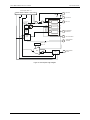
1
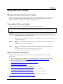
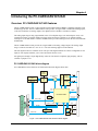
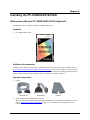
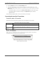
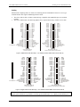
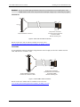
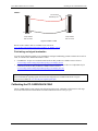
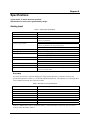
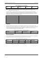
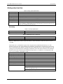
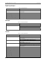
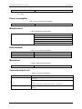
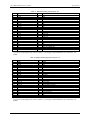
PC-CARD-DAS16/12AO Analog I/O and Digital I/O Board User’s Guide Document Revision 1, April, 2007 © Copyright 2007, Measurement Computing Corporation Your new Measurement Computing product comes with a fantastic extra — Management committed to your satisfaction! Refer to www.mccdaq.com/execteam.html for the names, titles, and contact information of each key executive at Measurement Computing. Thank you for choosing a Measurement Computing product—and congratulations! You own the finest, and you can now enjoy the protection of the most comprehensive warranties and unmatched phone tech support. It’s the embodiment of our mission: To provide PC-based data acquisition hardware and software that will save time and save money. Simple installations minimize the time between setting up your system and actually making measurements. We offer quick and simple access to outstanding live FREE technical support to help integrate MCC products into a DAQ system. Lifetime warranty: Every hardware product manufactured by Measurement Computing Corporation is warranted against defects in materials or workmanship for the life of the product. Products found defective are repaired or replaced promptly. Lifetime Harsh Environment Warranty®: We will replace any product manufactured by Measurement Computing Corporation that is damaged (even due to misuse) for only 50% of the current list price. I/O boards face some tough operating conditions, some more severe than the boards are designed to withstand. When a board becomes damaged, just return the unit with an order for its replacement at only 50% of the current list price. We don’t need to profit from your misfortune. By the way, we honor this warranty for any manufacturer’s board that we have a replacement for. 30 Day Money Back Guarantee: You may return any Measurement Computing Corporation product within 30 days of purchase for a full refund of the price paid for the product being returned. If you are not satisfied, or chose the wrong product by mistake, you do not have to keep it. Please call for an RMA number first. No credits or returns accepted without a copy of the original invoice. Some software products are subject to a repackaging fee. These warranties are in lieu of all other warranties, expressed or implied, including any implied warranty of merchantability or fitness for a particular application. The remedies provided herein are the buyer’s sole and exclusive remedies. Neither Measurement Computing Corporation, nor its employees shall be liable for any direct or indirect, special, incidental or consequential damage arising from the use of its products, even if Measurement Computing Corporation has been notified in advance of the possibility of such damages. HM PC-CARD-DAS16_12AO.doc 3 Trademark and Copyright Information TracerDAQ, Universal Library, Harsh Environment Warranty, Measurement Computing Corporation, and the Measurement Computing logo are either trademarks or registered trademarks of Measurement Computing Corporation. Windows, Microsoft, and Visual Studio are either trademarks or registered trademarks of Microsoft Corporation LabVIEW is a trademark of National Instruments. CompactFlash is a registered trademark of SanDisk Corporation. XBee and XBee-PRO are trademarks of MaxStream, Inc. All other trademarks are the property of their respective owners. Information furnished by Measurement Computing Corporation is believed to be accurate and reliable. However, no responsibility is assumed by Measurement Computing Corporation neither for its use; nor for any infringements of patents or other rights of third parties, which may result from its use. No license is granted by implication or otherwise under any patent or copyrights of Measurement Computing Corporation. All rights reserved. No part of this publication may be reproduced, stored in a retrieval system, or transmitted, in any form by any means, electronic, mechanical, by photocopying, recording, or otherwise without the prior written permission of Measurement Computing Corporation. Notice Measurement Computing Corporation does not authorize any Measurement Computing Corporation product for use in life support systems and/or devices without prior written consent from Measurement Computing Corporation. Life support devices/systems are devices or systems which, a) are intended for surgical implantation into the body, or b) support or sustain life and whose failure to perform can be reasonably expected to result in injury. Measurement Computing Corporation products are not designed with the components required, and are not subject to the testing required to ensure a level of reliability suitable for the treatment and diagnosis of people. 4 Table of Contents Preface About this User's Guide .......................................................................................................................7 What you will learn from this user's guide .........................................................................................................7 Conventions in this user's guide .........................................................................................................................7 Where to find more information.........................................................................................................................7 Chapter 1 Introducing the PC-CARD-DAS16/12AO.............................................................................................8 Overview: PC-CARD-DAS16/12AO features ...................................................................................................8 PC-CARD-DAS16/12AO block diagram ......................................................................................................................... 8 Software features ................................................................................................................................................9 Chapter 2 Installing the PC-CARD-DAS16/12AO...............................................................................................10 What comes with your PC-CARD-DAS16/12AO shipment? ..........................................................................10 Hardware .........................................................................................................................................................................10 Additional documentation................................................................................................................................................10 Optional components .......................................................................................................................................................10 Unpacking the PC-CARD-DAS16/12AO ........................................................................................................11 Installing the software ......................................................................................................................................11 Installing the PC-CARD-DAS16/12AO...........................................................................................................11 If your PCMCIA card is not detected ..............................................................................................................................11 Connecting the board for I/O operations ..........................................................................................................12 Connectors, cables – I/O connector .................................................................................................................................12 Pin out – I/O connector....................................................................................................................................................12 Field wiring and signal termination .................................................................................................................................15 Calibrating the PC-CARD-DAS16/12AO........................................................................................................15 Chapter 3 Programming and Developing Applications ....................................................................................16 Programming languages ...................................................................................................................................16 Packaged applications programs ......................................................................................................................16 Register-level programming .............................................................................................................................16 Chapter 4 Functional Details ...............................................................................................................................17 Conversion speed and amplification ................................................................................................................................17 Triggering and transfer ....................................................................................................................................................18 A/D pacer clock ...............................................................................................................................................................18 Chapter 5 Specifications......................................................................................................................................20 Analog input .....................................................................................................................................................20 Accuracy..........................................................................................................................................................................20 Crosstalk ..........................................................................................................................................................................21 Noise performance...........................................................................................................................................................21 Analog output section.......................................................................................................................................22 Accuracy..........................................................................................................................................................................22 Digital input/output ..........................................................................................................................................23 Interrupt ............................................................................................................................................................23 Counter .............................................................................................................................................................23 5 PC-CARD-DAS16/12AO User's Guide Power consumption ..........................................................................................................................................24 Miscellaneous ...................................................................................................................................................24 Environmental ..................................................................................................................................................24 Mechanical .......................................................................................................................................................24 Connector and pin out ......................................................................................................................................24 6 Preface About this User's Guide What you will learn from this user's guide This user's guide explains how to install, configure, and use the PC-CARD-DAS16/12AO so that you get the most out of its analog I/O, digital I/O and counter features. This user's guide also refers you to related documents available on our web site, and to technical support resources. Conventions in this user's guide The following conventions are used in this manual to convey special information: For more information on … Text presented in a box signifies additional information and helpful hints related to the subject matter you are reading. Caution! Shaded caution statements present information to help you avoid injuring yourself and others, damaging your hardware, or losing your data. <#:#> Angle brackets that enclose numbers separated by a colon signify a range of numbers, such as those assigned to registers, bit settings, etc. bold text Bold text is used for the names of objects on the screen, such as buttons, text boxes, and check boxes. For example: 1. Insert the disk or CD and click the OK button. italic text Italic text is used for the names of manuals and help topic titles, and to emphasize a word or phrase. For example: The InstaCal installation procedure is explained in the Quick Start Guide. Never touch the exposed pins or circuit connections on the board. Where to find more information The following electronic documents provide information relevant to the operation of the PC-CARDDAS16/12AO. MCC's Specifications: PC-CARD-DAS16/12AO (the PDF version of the Specifications chapter in this guide) is available on our web site at www.mccdaq.com/pdfs/PC-CARD-DAS16-12AO.pdf. MCC's Quick Start Guide is available on our web site at www.mccdaq.com/PDFmanuals/DAQ-Software-Quick-Start.pdf. MCC's Guide to Signal Connections is available on our web site at www.mccdaq.com/signals/signals.pdf. MCC's Universal Library User's Guide is available on our web site at www.mccdaq.com/PDFmanuals/sm-ul-user-guide.pdf. MCC's Universal Library Function Reference is available on our web site at www.mccdaq.com/PDFmanuals/sm-ul-functions.pdf. MCC's Universal Library for LabVIEW™ User’s Guide is available on our web site at www.mccdaq.com/PDFmanuals/SM-UL-LabVIEW.pdf. PC-CARD-DAS16/12AO User's Guide (this document) is also available on our web site at www.mccdaq.com/PDFmanuals/PC-CARD-DAS16-12AO.pdf. 7 Chapter 1 Introducing the PC-CARD-DAS16/12AO Overview: PC-CARD-DAS16/12AO features The PC-CARD-DAS16/12AO is a data acquisition and control board for IBM PC compatible computers with PCMCIA type II slots. The PC-CARD-DAS16/12AO provides 16 single-ended or 8 differential analog inputs, 12-bit A/D resolution, two analog outputs, four digital I/O lines, and three 16-bit down counters. The analog input range is fully programmable in one of four bipolar ranges. An on-board pacer clock, or an external pacer input, or software polling can trigger A/D conversions. Transfers are via software polling, interrupt service or REP-INSW. A 4096-word FIFO buffer provides buffering between the A/D circuit and the PCMCIA bus. The PC-CARD-DAS16/12AO provides two single-ended 12-bit analog voltage outputs. The analog output range is software selectable for ±10 V or ±5 V. The selected range applies to both channels. The four digital I/O bits are available on one 4-bit port. The digital channels are software configurable as four inputs or four outputs, and allow you to sense and control discrete events. All signals pass through a 50-pin high-density connector. The board is completely plug-and-play, with no switches or jumpers to set. PC-CARD-DAS16/12AO block diagram PC-CARD-DAS16/12AO functions are illustrated in the block diagram shown here. FIFO Buffer 4K x 8 HI_BYTE FIFO Buffer 4K x 8 LOW_BYTE Programmable-Gain Amplifier ADC 12-bit 10 µS A/D Pacer Single-ended or differential select switching Precision Voltage Reference 8 channel Analog MUX 8 channel Analog MUX Control /Clock Digital I/O 4-bits Counter/Pacer 10 MHz Oscillator Controller FPGA Pacer Control /EXT TRIG Control, IREQ Host Bus Adaptor VREF Counter 1, 3 Out 2 Data Bus Attribute Memory Address Bus DAC 12-bit VOUT 0 DAC 12-bit VOUT 1 Figure 1. PC-CARD-DAS16/12AO functional block diagram 8 PC-CARD-DAS16/12AO User's Guide Introducing the PC-CARD-DAS16/12AO Software features For information on the features of InstaCal and the other software included with your PC-CARDDAS16/12AO, refer to the Quick Start Guide that shipped with your device. The Quick Start Guide is also available in PDF at www.mccdaq.com/PDFmanuals/DAQ-Software-Quick-Start.pdf. Check www.mccdaq.com/download.htm for the latest software version. 9 Chapter 2 Installing the PC-CARD-DAS16/12AO What comes with your PC-CARD-DAS16/12AO shipment? The following items are shipped with the PC-CARD-DAS16/12AO. Hardware PC-CARD-DAS16/12AO Additional documentation In addition to this hardware user's guide, you should also receive the Quick Start Guide (available in PDF at www.mccdaq.com/PDFmanuals/DAQ-Software-Quick-Start.pdf). This booklet supplies a brief description of the software you received with your PC-CARD-DAS16/12AO and information regarding installation of that software. Please read this booklet completely before installing any software or hardware. Optional components Cables CPCC-50F-39 CPCC-50M-4 C50FF-x Signal termination and conditioning accessories MCC provides signal conditioning and termination products for use with the PC-CARD-DAS16/12AO. Refer to Field wiring and signal termination on page 15 for a complete list of compatible accessory products. 10 PC-CARD-DAS16/12AO User's Guide Installing the PC-CARD-DAS16/12AO Unpacking the PC-CARD-DAS16/12AO As with any electronic device, you should take care while handling to avoid damage from static electricity. Before removing the PC-CARD-DAS16/12AO from its packaging, ground yourself using a wrist strap or by simply touching the computer chassis or other grounded object to eliminate any stored static charge. If any components are missing or damaged, notify Measurement Computing Corporation immediately by phone, fax, or e-mail: Phone: 508-946-5100 and follow the instructions for reaching Tech Support. Fax: 508-946-9500 to the attention of Tech Support Email: [email protected] Installing the software Refer to the Quick Start Guide for instructions on installing the software on the Measurement Computing Data Acquisition Software CD. This booklet is available in PDF at www.mccdaq.com/PDFmanuals/DAQ-SoftwareQuick-Start.pdf. Installing the PC-CARD-DAS16/12AO The PC-CARD-DAS16/12AO board is completely plug-and-play. There are no switches or jumpers to set. To install your board, follow the steps below. Install the MCC DAQ software before you install your board The driver needed to run your board is installed with the MCC DAQ software. Therefore, you need to install the MCC DAQ software before you install your board. Refer to the Quick Start Guide for instructions on installing the software. To install your PC-Card, do the following: Insert the card into a free PC Card/PCMCIA type II or III slot. The key helps to insure that the cable is inserted in the correct orientation. You do not have to turn the computer off. The system is designed for power-on installation. You should hear an insertion beep when you insert the card. Figure 2. End view of the 50-pin PC-CARD connector showing proper orientation Windows automatically detects, recognizes, and configures the PC-CARD. You should hear an insertion beep when you insert the card into the slot. To verify that the card is recognized, go to Control Panel\System\Device Manager and the card should now appear under "DAS Component." If your PCMCIA card is not detected If the card is not detected by Windows, and you are not prompted for a driver after inserting the card, check that your computer's 32-bit PCMCIA drivers are installed and enabled. Do the following: 1. From your desktop, right-click on My Computer and select Properties. The System Properties dialog opens. 11 PC-CARD-DAS16/12AO User's Guide Installing the PC-CARD-DAS16/12AO 2. Select the Hardware tab and click on the Device Manager button. 3. Verify that "PCMCIA adapters" is listed in the Device Manager. If you don’t find this entry, or if the properties for the adapter indicate "this device is not working," you need to install or update your PCMCIA adapter drivers. o If the PCMCIA adapter is not listed, use the Add New Hardware Wizard to install PCMCIA support. o If the PCMCIA adapter is listed but not working, use the Update Driver option to install the appropriate drivers. After performing the update procedure, reboot your PC and insert your card again. Connecting the board for I/O operations Connectors, cables – I/O connector The table below lists the board connector, applicable cables, and compatible accessory products. Board connector, cables, and accessory equipment Connector type Compatible cables Compatible accessory products 50-pin connector CPCC-50F-39: 50-pin Micro connector to 50-pin female IDC, one-meter cable (39 inches). CPCC-50M-4: 50-pin Micro connector to 50-pin male IDC, 4 inch adapter cable. and C50FF-x: 50-pin IDC female to female cable. x = length in feet. CIO-MINI50 SCB-50 Pin out – I/O connector Figure 3 shows a PC-CARD-DAS16/12AO case looking into the male mini-connector. The connector is mechanically keyed to insure that the cable is inserted correctly. Figure 3. 50-pin I/O mini-connector 12 PC-CARD-DAS16/12AO User's Guide Installing the PC-CARD-DAS16/12AO Cabling Measurement Computing offers two cables for connecting the PC-CARD-DAS16/12AO to a screw-type terminal board or other signal conditioning interface board: The CPCC-50F-39 cable: 39 inches (990 mm) long; compatible with standard 50-pin screw terminal products. The CPCC-50M-4 cable: four-inch long adapter cable; required when using a C50FF-x series cable. 1 50 PC-CARD end AGND CH0 LO CH1 LO CH2 LO CH3 LO CH4 LO CH5 LO CH6 LO CH7 LO N/C N/C N/C N/C DIO0 DIO2 N/C N/C DA GND0 DA GND1 CTR1 CLK CTR1 OUT External Interrupt A/D External Trigger A/D Pacer Out N/C 2 4 6 8 10 12 14 16 18 20 22 24 26 28 30 32 34 36 38 40 42 44 46 48 50 1 3 5 7 9 11 13 15 17 19 21 23 25 27 29 31 33 35 37 39 41 43 45 47 49 CH0 HI CH1 HI CH2 HI CH3 HI CH4 HI CH5 HI CH6 HI CH7 HI AGND N/C N/C N/C DGND DIO1 DIO3 DIO5 DIO7 DA OUT0 DA OUT1 CTR1 GATE A/D External Pacer A/D Pacer Gate N/C +5V Power DGND CH0 HI CH1 HI CH2 HI CH3 HI CH4 HI CH5 HI CH6 HI CH7 HI AGND N/C N/C N/C DGND DIO1 DIO3 N/C N/C DA OUT0 DA OUT1 CTR1 GATE A/D External Pacer A/D Pacer Gate N/C +5V Power DGND 2 4 6 8 10 12 14 16 18 20 22 24 26 28 30 32 34 36 38 40 42 44 46 48 50 1 3 5 7 9 11 13 15 17 19 21 23 25 27 29 31 33 35 37 39 41 43 45 47 49 AGND CH0 LO CH1 LO CH2 LO CH3 LO CH4 LO CH5 LO CH6 LO CH7 LO N/C N/C N/C N/C DIO0 DIO2 DIO4 DIO6 DA GND0 DA GND1 CTR1 CLK CTR1 OUT External Interrupt A/D External Trigger A/D Pacer Out N/C CPCC-50F-39 cable end (connect to screw terminal or relay boards) CPCC-50M-4 cable end (connect to C50FF-x) Figure 4. Differential mode cable map — PC-CARD to CPCC-50M-4 and to CPCC-50F-39 1 50 PC-CARD end AGND CH8 IN CH9 IN CH10 IN CH11 IN CH12 IN CH13 IN CH14 IN CH15 IN N/C N/C N/C N/C DIO0 DIO2 DIO4 DIO6 DA GND0 DA GND1 CTR1 CLK CTR1 OUT External Interrupt A/D External Trigger A/D Pacer Out N/C 1 3 5 7 9 11 13 15 17 19 21 23 25 27 29 31 33 35 37 39 41 43 45 47 49 2 4 6 8 10 12 14 16 18 20 22 24 26 28 30 32 34 36 38 40 42 44 46 48 50 CH0 IN CH1 IN CH2 IN CH3 IN CH4 IN CH5 IN CH6 IN CH7 IN AGND N/C N/C N/C DGND DIO1 DIO3 DIO5 DIO7 DA OUT0 DA OUT1 CTR1 GATE A/D External Pacer A/D Pacer Gate N/C +5V Power DGND CH0 IN CH1 IN CH2 IN CH3 IN CH4 IN CH5 IN CH6 IN CH7 IN AGND N/C N/C N/C DGND DIO1 DIO3 DIO5 DIO7 DA OUT0 DA OUT1 CTR1 GATE A/D External Pacer A/D Pacer Gate N/C +5V Power DGND 2 4 6 8 10 12 14 16 18 20 22 24 26 28 30 32 34 36 38 40 42 44 46 48 50 1 3 5 7 9 11 13 15 17 19 21 23 25 27 29 31 33 35 37 39 41 43 45 47 49 AGND CH8 IN CH9 IN CH10 IN CH11 IN CH12 IN CH13 IN CH14 IN CH15 IN N/C N/C N/C N/C DIO0 DIO2 DIO4 DIO6 DA GND0 DA GND1 CTR1 CLK CTR1 OUT External Interrupt A/D External Trigger A/D Pacer Out N/C CPCC-50F-39 cable end (connect to screw terminal or relay boards) CPCC-50M-4 cable end (connect to C50FF-x) Figure 5. Single-ended mode cable map — PC-CARD to CPCC-50M-4 and to CPCC-50F-39 Note Digital signals should not be grounded to an analog ground (AGND) pin. Use a digital ground (DGND) pin. 13 PC-CARD-DAS16/12AO User's Guide Installing the PC-CARD-DAS16/12AO Caution! Do not exceed the input specifications. There are no socketed or user serviceable parts in a PCCARD-DAS16/12AO. Check the specifications and input voltages before connecting any signals. CPCC-50F-39 49 50 50 Key 1 Dot 1 2 50-pin micro connector. Connect to the I/O connector on the PC-CARD with the dot facing UP. 50-pin female IDC connector. Figure 6. CPCC-50F-39 cable connections Details on the CPCC-50F-39 cable are available on our web site at www.mccdaq.com/cbicatalog/cbiproduct.asp?dept_id=105&pf_id=1379. CPCC-50M-4 If your application requires a cable that is longer than one meter in length, use the CPCC-50M-4 four-inch cable, and connect to a C50FF-x cable. 50 49 50 1 2 Dot 1 50-pin micro connector. Connect to the I/O connector on the PC-CARD with the dot facing UP. 50-pin male IDC connector. Connect to a C50FF-x cable. Figure 7. CPCC-50M-4 cable connections Details on the CPCC-50M-4 cable are available on our web site at www.mccdaq.com/cbicatalog/cbiproduct.asp?dept_id=96&pf_id=1380. 14 PC-CARD-DAS16/12AO User's Guide Installing the PC-CARD-DAS16/12AO C50FF-x 2 1 50 49 The red stripe identifies pin # 1 50-pin female IDC connector 2 1 50 49 50-pin female IDC connector Figure 8. C50FF-x cable Details on the C50FF-x cable are available on our web site at www.mccdaq.com/cbicatalog/cbiproduct.asp?dept_id=104&pf_id=136. Field wiring and signal termination You can use the following cabling, screw termination, and signal conditioning products with the CPCC-50F-39 cable, or with the CPCC-50M-4 and C50FF-x cables: CIO-MINI50 – 50-pin screw terminal board. Details on this product are available on our web site at www.mccdaq.com/cbicatalog/cbiproduct.asp?dept_id=102&pf_id=258. SCB-50 – 50 conductor, shielded signal connection/screw terminal box provides two independent 50-pin connections. Details on this product are available on our web site at www.mccdaq.com/cbicatalog/cbiproduct.asp?dept_id=196&pf_id=1168. Information on signal connections General information regarding signal connection and configuration is available in the Guide to Signal Connections (available at www.mccdaq.com/signals/signals.pdf). Calibrating the PC-CARD-DAS16/12AO The PC-CARD-DAS16/12AO features auto-calibration with InstaCal. Calibration coefficients for each range are stored on board in nonvolatile RAM. The normal calibration interval is once per year. 15 Chapter 3 Programming and Developing Applications After following the installation instructions in Chapter 2, your board should now be installed and ready for use. In general there may be no correspondence among registers for different boards. Software written at the register-level for other models does not function correctly with your board. Programming languages Measurement Computing’s Universal Library provides access to board functions from a variety of Windows programming languages. If you are planning to write programs, or would like to run the example programs for Visual Basic or any other language, please refer to the Universal Library User's Guide (available on our web site at www.mccdaq.com/PDFmanuals/sm-ul-user-guide.pdf). Packaged applications programs Many packaged application programs now have drivers for your board. If the package you own does not have drivers for the board, please fax or e-mail the package name and the revision number from the install disks. We will research the package for you and advise how to obtain drivers. Some application drivers are included with the Universal Library package, but not with the application package. If you have purchased an application package directly from the software vendor, you may need to purchase our Universal Library and drivers. Please contact us by phone, fax or e-mail: Phone: 508-946-5100 and follow the instructions for reaching Tech Support. Fax: 508-946-9500 to the attention of Tech Support Email: [email protected] Register-level programming You should use the Universal Library or one of the packaged application programs mentioned above to control your board. Only experienced programmers should try register-level programming. 16 Chapter 4 Functional Details The 12-bit A/D converter provides a resolution of 1/4096 parts of full scale. The smallest reading of full scale (1 part in 4096) is called a Least Significant Bit (LSB). Four bipolar and four unipolar ranges may be set by software. These are: Analog input ranges Bipolar Unipolar Range Resolution Range Resolution ±10 V ±5 V ±2.5 V ±1.25 V 4.88 mV 2.44 mV 1.22 mV 0.61 mV 0 to 10 V 0 to 5 V 0 to 2.5 V 0 to 1.25 V 2.44 mV 1.22 mV 0.61 mV 305 µV The input range is controlled by a programmable amplifier. Conversion speed and amplification The A/D converter and sample & hold circuit captures and digitizes a signal in 10 µs. The time it takes to complete an A/D conversion remains constant in all conditions and at all throughput rates. When you request a sample rate of say 20 kHz, the A/D converter is still converting the signal in 10 µs. The 20 kHz rate comes from the fact that conversions are being initiated only every 50 µs. What factors limit conversion speed? The first is clearly the A/D. A 10 µs conversion speed translates to a maximum throughput of 100 kHz. The second limiting factor can be the analog front end. The front end may consist of a multiplexer and a programmable gain amplifier. The speed at which these circuits can switch may also limit the throughput of the A/D board. That is, the rate at which it can acquire, convert and transfer a signal with full accuracy. Accuracy is the key term here. The A/D can always run at full speed, but has the front end settled and captured a true, accurate signal? What about input range vs. speed? Here is where the design of the analog front end is critical to maintaining total throughput. Most A/D converters have a fixed input range, typically +/-5V. It is the analog front end that amplifies low level signals and adjusts unipolar signals to match the A/D converter's standard input. A poorly designed analog front end will show up very quickly in the throughput specifications. If you see that an A/D board has high throughput in only one or two ranges but is slowed greatly at all other ranges, you are seeing the practical implications of a poor front end design. The PC-CARD-DAS16/12AO achieves 100 kHz in all of the eight ranges. 17 PC-CARD-DAS16/12AO User's Guide Functional Details Triggering and transfer A trigger begins an acquisition/transfer cycle. There are three ways to trigger a PC-CARD-DAS16/12AO: programmable pacer, software, or external. The trigger source selection is programmable. The programmable pacer is the product of two 16-bit counters dividing a 10 MHz or 1 MHz pulse derived from a 10 MHz crystal oscillator which can be used to trigger any number of paced conversions. A single conversion can be triggered by software at any time. External trigger, pacer clock and interrupt signals may also be used to control conversions and synchronize to external events. After a conversion is made, the sample is routed to a 4096-word (sample) FIFO buffer from which it may be retrieved one sample at a time or in blocks via REP-INSW transfers. How do FIFO size and design affect throughput? The 4096 12-bit sample FIFO buffer stores samples from the A/D converter as they are being converted. When a block of samples is ready and when the PC is ready, the FIFO is emptied into system memory. Most FIFO designs employ a half-full transfer initiation circuit. When the FIFO is half full, the transfer request is made. Samples continue to fill the second half of the FIFO while the CPU responds to the transfer request and transfers data to system memory. A/D pacer clock Many analog acquisitions can be handled by a simple on-board rate divider created by combining a crystal oscillator with a programmable counter. For those, the on-board 82C54 programmable rate generator (counter) supplies the pacing. Some applications require more flexible rate control. The PC-CARD-DAS16/12AO analog conversions can be externally paced and thereby synchronized with events external to the PC. Conversions can be held off until some external event, such as a not-to-exceed condition is met. Conversions can be externally gated so that samples are taken only when an event of interest is occurring, such as a process going over normal limits. Figure 9 shows a logic diagram of the A/D pacer clock and counters. 18 PC-CARD-DAS16/12AO User's Guide Functional Details Control Register BASE + 6h TRGPOL TRGSEL TRGCLR CLK2 CTR1 10K 5 GATE 1/10 1/10 Counter 1 39 CRT1 CLK 40 CTR1 GATE 5 10K OUT 41 CTR1 OUT 47 A/D INTERNAL PACER OUT CLK 0 CLK 1 GATE 10 MHz OSC CLK Counter 2 Counter 3 OUT OUT GATE Trigger Logic TS1 A/D Convert CLock 1 TS0 A/D PACER GATE 45 A/D EXTERNAL TRIGGER Control register BASE + 4h 0 3 2 MUX 1 0 44 Trigger Logic S/W CONVERT Figure 9. Counter/pacer logic diagram 19 42 A/D EXTERNAL CLOCK Chapter 5 Specifications Typical for 25 °C unless otherwise specified. Specifications in italic text are guaranteed by design. Analog input Table 1. Analog input specifications A/D converter type Resolution Number of channels Input ranges A/D pacing (software programmable) A/D trigger sources A/D triggering modes A/D gate sources Burst mode Data transfer A/D conversion time Calibrated throughput Calibration ADS7804 12 bits 16 single-ended / 8 differential, software selectable ±10 V, ±5 V, ±2.5 V, ±1.25 V, 0 to 10 V, 0 to 5 V, 0 to 2.5 V, 0 to 1.25 V, software programmable Internal counter - 82C54. External source - A/D External Pacer, software programmable for rising or falling edge Software polled External edge trigger (A/D External Trigger) Rising or falling edge trigger - software selectable A/D External Trigger, gate high or low, software selectable A/D Pacer Gate, gate high Software selectable option, burst rate = 100 kHz From 4k sample FIFO via REPINSW Programmed I/O 10 µs max 100 kHz Auto-calibration, calibration factors for each range stored on board in nonvolatile RAM Accuracy Accuracies are listed for a 100 kHz sampling rate, single channel operation, a 60 minute warm-up, and operational temperatures within ±2 °C of internal calibration temperature. The calibrator test source high side is tied to Channel 0 In and the low side tied to AGND. Table 2. Absolute accuracy specifications Range Absolute Accuracy ±10.00 V ±5.000 V ±2.500 V ±1.250 V 0 to 10.00 V 0 to 5.000 V 0 to 2.500 V 0 to 1.250 V ±3 LSB max ±3 LSB max ±3 LSB max ±3 LSB max ±3 LSB max ±3 LSB max ±3 LSB max ±3 LSB max Each PC-CARD-DAS16/12AO is tested at the factory to assure the board’s overall error does not exceed accuracy limits described in Table 2. 20 PC-CARD-DAS16/12AO User's Guide Specifications Table 3. Calibrated accuracy specifications (Note 1) Range Gain Error Offset Error DLE All ranges ±1.0 max ±1.0 max ±1.0 max ILE (Note 1) ±1.0 max Note 1: These are the intrinsic specifications of the ADC. Software calibration may introduce a small additional amount of linearity error. As shown in Table 3, total board error is a combination of gain, offset, differential linearity and integral linearity error. The theoretical worst-case error of the board may be calculated by summing these component errors. Worst case errors are realized only in the unlikely event that each of the component errors are at their maximum level, and causing error in the same direction. Analog input full-scale gain drift Analog input zero drift Overall analog input drift Common mode range CMRR @ 60 Hz Input leakage current Input impedance Absolute maximum input voltage ±0.66 LSB/°C max ±0.61 LSB/°C max ±1.27 LSB/°C max ±10 V min -72 dB min ±20 nA max 10 MOhms min +55/-40 V (Fault Protected via Input Mux) Crosstalk Crosstalk is defined here as the influence of one channel upon another when scanning two channels at the maximum rate. A full scale 100 Hz triangle wave is input on channel 1; channel 0 is tied to analog ground at the connector. The table below summarizes the influence of channel 1 on channel 0 with the effects of noise removed. The residue on channel zero is described in LSB's. Table 4. Channel to channel crosstalk specifications Condition Crosstalk Per channel Rate ADC Rate All ranges 1LSB pk-pk 50 kHz 100 kHz Noise performance Table 5 summarizes the noise performance for the PC-CARD-DAS16/12AO. Noise distribution is determined by gathering 50 K samples at 100 kHz with inputs tied to ground at the user connector. Table 5. Noise performance specifications Range % within ±2 LSBs % within ±1 LSB Typical LSBrms* Max LSBrms* 0 to 1.250 V All other ranges 100% 100% 99% 100% 0.61 0.45 0.90 0.75 * RMS noise is defined as the peak-to-peak bin spread divided by 6.6. 21 PC-CARD-DAS16/12AO User's Guide Specifications Analog output section Table 6. Analog output specifications D/A converter type Resolution Number of channels Configuration Output Range D/A pacing Data transfer Throughput LTC1446 12 bits 2 Voltage output, single-ended ±10 V, ±5 V. Software selectable. Selected range applies to both channels. Software Programmed I/O System dependent. Using the Universal Library programmed output function (cbAout) in a loop in Visual Basic, a typical update rate of 5.5 kHz (±200 Hz) can be expected. The rate was measured on a 600MHz Pentium III based PC. Accuracy Table 7. Accuracy specifications Absolute accuracy Differential linearity error ±5.0 LSB worst case error ±0.5 LSB max Table 8. Calibrated accuracy components Gain error Offset error Integral linearity error ±1.0 LSB max ±1.0 LSB max ±5.0 LSB max Each PC-CARD-DAS16/12AO is tested at the factory to assure the board’s overall error does not exceed ±5.0 LSB. Total board error is a combination of gain, offset, integral linearity and differential linearity error. The theoretical worst-case error of the board may be calculated by summing these component errors. Worst case error is realized only in the unlikely event that each of the component errors are at their maximum level, and causing error in the same direction. Although an examination of the chart and a summation of the maximum theoretical errors shows that the board could theoretically exhibit a ±7.5 LSB error, our testing assures this error is never realized in a board that we ship. Monotonicity Analog output full-scale gain drift Analog output zero drift Overall analog output drift Slew rate Current drive Output short-circuit duration Output coupling Output impedance Miscellaneous Guaranteed monotonic over temperature ±0.60 LSB/°C max ±0.07 LSB/°C max ±0.67 LSB/°C max ± 0.5 V/µs min ±2 mA min Indefinite @ 12 mA DC 0.1 ohms max Double buffered output latches Coding: Inverted Offset Binary: 0 code = +FS, 4095 code = -FS Output voltage on power up and reset: +10 V (+FS) 22 PC-CARD-DAS16/12AO User's Guide Specifications Digital input/output Table 9. DIO specifications Digital type Number of I/O Configuration Input low voltage Input high voltage Output low voltage (IOL = 4 mA) Output high voltage (IOH = -4 mA) Absolute maximum input voltage Power-up / reset state FPGA 4 One port, programmable 4 input / 4 output 0.8 V max 2.0 V min 0.32 V max 3.86 V min -0.5 V , +5.5 V Input mode (high impedance) Interrupt Table 10. Interrupt specifications Interrupts Interrupt enable Interrupt sources Programmable: Levels 2 – 15 Programmable. Default = disabled. External (External Interrupt) A/D End-of-channel-scan A/D FIFO-not-empty A/D FIFO-half-full A/D Pacer Counter Table 11. Counter specifications Counter type Configuration Counter 1 - User counter Counter 2 - ADC Pacer Lower Divider Counter 3 - ADC Pacer Upper Divider Clock input frequency High pulse width (clock input) Low pulse width (clock input) Gate width high Gate width low Input low voltage Input high voltage Output low voltage Output high voltage Crystal oscillator frequency 82C54 3 down counters, 16 bits each Source: Programmable external (Ctr 1 Clk) or 100kHz internal source Gate: Available at connector (Ctr 1 Gate), pulled to logic high via 10K resistor. See Note 2. Output: Available at connector (Ctr 1 Out) Source: Programmable, 1MHz or 10 MHz internal source Gate: Available at connector (A/D Pacer Gate), pulled to logic high via 10K resistor. Output: Chained to Counter 3 Clock Source: Counter 2 Output Gate: Internal Output: Programmable as ADC Pacer clock. Available at user connector (ADC Pacer out) 10 MHz max 30 ns min 50 ns min 50 ns min 50 ns min 0.8 V max 2.0 V min 0.4 V max 3.0 V min 10 MHz 23 PC-CARD-DAS16/12AO User's Guide Specifications Frequency accuracy 50 ppm Note 2: If you are not driving the gate of User Counter 1, it is strongly recommended that it be connected to +5V (VDD). Power consumption Table 12. Power consumption specifications +5V quiescent 85 mA typical, 125 mA max Miscellaneous Table 13. Miscellaneous specifications +5 Volts Available at I/O connector (+5V Power) Protected by resettable fuse: Hold current: 350 mA max @ 20 °C still air Trip current: Trip and recovery time: On resistance: 700 mA min @ 20 °C still air 100 mS max 1.3 Ohms max Environmental Table 14. Environmental specifications Operating temperature range Storage temperature range Humidity 0 to 70 °C -40 to 100 °C 0 to 95% non-condensing Mechanical Table 15. Mechanical specifications Card dimensions PCMCIA type II: 85.6 mm (L) x 54.0 mm (W) x 5.0 mm (H) Connector and pin out Table 16. Connector specifications Connector type Compatible cables Compatible accessory products 50-pin connector CPCC-50F-39: 50-pin Micro connector to 50-pin female IDC, one-meter cable (39 inches). CPCC-50M-4: 50-pin Micro connector to 50-pin male IDC, 4 inch adapter cable. and C50FF-x: 50-pin IDC female to female cable. x = length in feet. CIO-MINI50 SCB-50 24 PC-CARD-DAS16/12AO User's Guide Specifications Table 17. Differential analog input mode pin out Pin 1 2 3 4 5 6 7 8 9 10 11 12 13 14 15 16 17 18 19 20 21 22 23 24 25 Signal Name AGND CH0 HI CH0 LO CH1 HI CH1 LO CH2 HI CH2 LO CH3 HI CH3 LO CH4 HI CH4 LO CH5 HI CH5 LO CH6 HI CH6 LO CH7 HI CH7 LO AGND N/C N/C N/C N/C N/C N/C N/C Pin 26 27 28 29 30 31 32 33 34 35 36 37 38 39 40 41 42 43 44 45 46 47 48 49 50 Signal Name DGND DIO0 DIO1 DIO2 DIO3 N/C N/C N/C N/C DA GND0 DA OUT0 DA GND1 DA OUT1 CTR1 CLK CTR1 GATE * CTR1 OUT A/D EXTERNAL PACER EXTERNAL INTERRUPT A/D PACER GATE A/D EXTERNAL TRIGGER N/C A/D PACER OUT VDD +5V POWER OUT N/C DGND * If you are not driving the gate of User Counter 1, it is strongly recommended that it be connected to +5V (VDD). Table 18. Single-ended analog input mode pin out Pin 1 2 3 4 5 6 7 8 9 10 11 12 13 14 15 16 17 18 19 20 21 22 23 24 25 Signal Name AGND CH0 IN CH8 IN CH1 IN CH9 IN CH2 IN CH10 IN CH3 IN CH11 IN CH4 IN CH12 IN CH5 IN CH13 IN CH6 IN CH14 IN CH7 IN CH15 IN AGND N/C N/C N/C N/C N/C N/C N/C Pin 26 27 28 29 30 31 32 33 34 35 36 37 38 39 40 41 42 43 44 45 46 47 48 49 50 Signal Name DGND DIO0 DIO1 DIO2 DIO3 N/C N/C N/C N/C DA GND0 DA OUT0 DA GND1 DA OUT1 CTR1 CLK CTR1 GATE * CTR1 OUT A/D EXTERNAL PACER EXTERNAL INTERRUPT A/D PACER GATE A/D EXTERNAL TRIGGER N/C A/D PACER OUT VDD +5V POWER OUT N/C DGND * If you are not driving the gate of User Counter 1, it is strongly recommended that it be connected to +5V (VDD). 25 Declaration of Conformity Manufacturer: Address: Category: Measurement Computing Corporation 10 Commerce Way Suite 1008 Norton, MA 02766 USA Electrical equipment for measurement, control and laboratory use. Measurement Computing Corporation declares under sole responsibility that the product PC-CARD-DAS16/12AO to which this declaration relates is in conformity with the relevant provisions of the following standards or other documents: EU EMC Directive 89/336/EEC: Electromagnetic Compatibility, EN 61326 (1997) Amendment 1 (1998) Emissions: Group 1, Class A EN 55011 (1990)/CISPR 11: Radiated and Conducted emissions. Immunity: EN61326, Annex A IEC 1000-4-2 (1995): Electrostatic Discharge immunity, Criteria C. IEC 1000-4-3 (1995): Radiated Electromagnetic Field immunity Criteria B. IEC 1000-4-4 (1995): Electric Fast Transient Burst immunity Criteria B. IEC 1000-4-5 (1995): Surge immunity Criteria A. IEC 1000-4-6 (1996): Radio Frequency Common Mode immunity Criteria C. IEC 1000-4-11 (1994): Voltage Dip and Interrupt immunity Criteria A. Tests to IEC 1000-4-8 were not required. The PC cards do not contain components that would be susceptible to magnetic fields. Declaration of Conformity based on tests conducted by Chomerics Test Services, Woburn, MA 01801, USA in June, 2004. Test records are outlined in Chomerics Test Report #EMI3903.04. We hereby declare that the equipment specified conforms to the above Directives and Standards. Carl Haapaoja, Director of Quality Assurance Measurement Computing Corporation 10 Commerce Way Suite 1008 Norton, Massachusetts 02766 (508) 946-5100 Fax: (508) 946-9500 E-mail: [email protected] www.mccdaq.com