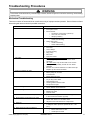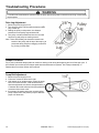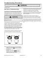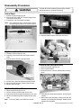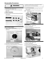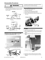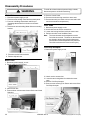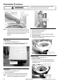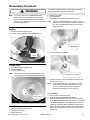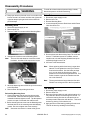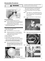
1
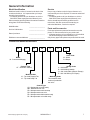
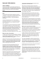
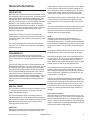
Service
This manual is to be used by qualified appliance
technicians only. Maytag does not assume any
responsibility for property damage or personal
injury for improper service procedures done by
an unqualified person.
Commercial
Top Load
Washer
This Base Manual covers general information
Refer to individual Technical Sheet
for information on specific models
This manual includes, but is
not limited to the following:
MAT12PDA
MAT12PDB
MAT12PDC
MAT12PDD
MAT12PDS
MAT12PRA
MAT12PRB
MAT12PRD
MAT12PRS
MAT12PSA
MAT12PSB
MAT12PSD
MAT12CSA
MAT12CSD
MAT13MNA
MAT13MND
MAT13PNA
MAT13PND
16022842
Revision 0
December 2003
Important Information
Important Notices for Servicers and Consumers
Maytag will not be responsible for personal injury or property damage from improper service procedures. Pride and
workmanship go into every product to provide our customers with quality products. It is possible, however, that during
its lifetime a product may require service. Products should be serviced only by a qualified service technician who is
familiar with the safety procedures required in the repair and who is equipped with the proper tools, parts, testing
instruments and the appropriate service information. IT IS THE TECHNICIANS RESPONSIBILITY TO REVIEW ALL
APPROPRIATE SERVICE INFORMATION BEFORE BEGINNING REPAIRS.
!
WARNING
To avoid risk of severe personal injury or death, disconnect power before working/servicing on appliance to avoid
electrical shock.
To locate an authorized servicer, please consult your telephone book or the distributor from whom you purchased this
product. For further assistance:
Contact your local commercial product distributor or visit Web site www.maytagcommerciallaundry.com
Recognize Safety Symbols, Words, and Labels
! DANGER
DANGER—Immediate hazards which WILL result in severe personal injury or death.
!
WARNING
WARNING—Hazards or unsafe practices which COULD result in severe personal injury or death.
!
CAUTION
CAUTION—Hazards or unsafe practices which COULD result in minor personal injury, product or property
damage.
2
16022842 Rev. 0
©2003 Maytag Appliances Company
Table of Contents
Important Information .................................................... 2
Important Safety Information ......................................... 4
General Information
Model Identification .................................................... 7
Model Nomenclature .................................................. 7
How It Works ............................................................. 8
Tools For Servicing ................................................... 10
Troubleshooting Procedures
Mechanical Troubleshooting ..................................... 11
Drive Lug Adjustment ............................................. 12
Damper Pad Noise ................................................ 12
Pump Belt Adjustment ........................................... 12
Electrical Troubleshooting ........................................ 13
Component Testing ................................................ 14
Motor Testing ......................................................... 14
Disassembly Procedures ............................................. 16
Control Panel ............................................................ 16
MN (Manual) Timer ................................................... 16
CS (Coin Slide) Timer ............................................... 16
Control Board (Microprocessor) ................................ 16
Touch Pad ................................................................ 17
Cycle Selector Switch .............................................. 17
Transformer .............................................................. 17
Motor Run Relay ....................................................... 17
Reversing Motor Relay .............................................. 18
Indicator Light ........................................................... 18
Lid Switch Assembly (Prior series 15) ...................... 18
Lid Switch Assembly (After series 15) ...................... 18
Unbalance Lever and Plunger Assembly ................... 19
©2003 Maytag Appliances Company
Disassembly Procedures(continued) ...............................
Pressure Switch ....................................................... 19
Air Dome .................................................................. 19
Water Valve .............................................................. 20
Meter Case ............................................................... 20
Coin Slide ................................................................. 20
Coin Drop Acceptor ................................................... 20
Coin Sensor .............................................................. 21
Service Door Switch .................................................. 21
Coin Vault Switch ..................................................... 21
Lid ............................................................................ 21
Front Panel ............................................................... 22
Top Cover .................................................................. 22
Tub Cover ................................................................. 22
Balance Ring ............................................................ 22
Agitator ..................................................................... 23
Access Plug ............................................................. 23
Inner Tub .................................................................. 23
Mounting Stem ......................................................... 24
Outer Tub ................................................................. 24
Tub Bearing .............................................................. 24
Transmission ............................................................ 25
Lip Seal .................................................................... 26
Damper Assembly .................................................... 27
Brake Package and Radial Bearing .......................... 27
Belts ......................................................................... 28
Drive Pulley and Rotor Bearing ................................. 28
Pump ........................................................................ 29
Drive Motor and Motor Base ..................................... 29
16022842 Rev. 0
3
Important Safety Information
!
WARNING
To reduce the risk of fire, electric shock, serious injury
or death to persons when using your washer, follow
these basic precautions:
• Read all instructions before using the washer.
• Refer to the Grounding Instructions in the Installation
Manual for the proper grounding of the washer.
• Do not wash articles that have been previously
cleaned in, washed in, soaked in, or spotted with
gasoline, dry-cleaning solvents, or other flammable or
explosive substances as they give off vapors that
could ignite or explode.
• Do not add gasoline, dry-cleaning solvents, or other
flammable or explosive substances to the wash
water. These substances give off vapors that could
ignite or explode.
• Under certain conditions, hydrogen gas may be
produced in a hot water system that has not been
used for two weeks or more. Hydrogen gas is
explosive. If the hot water system has not been used
for such a period, before using a washing machine or
combination washer-dryer, turn on all hot water
faucets and let the water flow from each for several
minutes. This will release any accumulated hydrogen
gas. The gas is flammable, do not smoke or use an
open flame during this time.
• Do not allow children to play on or in the washer.
Close supervision of children is necessary when the
washer is used near children. This is a safety rule for
all appliances.
• Before the washer is removed from service or
discarded, remove the lid to the washing
compartment.
• Do not reach into the washer if the wash tub is
moving.
• Do not install or store the washer where it will be
exposed to water and/or weather.
• Do not tamper with the controls.
• Do not repair or replace any part of the washer, or
attempt any servicing unless specifically
recommended in the User-Maintenance instructions
or in published user-repair instructions that you
understand and have the skills to carry out.
• To reduce the risk of an electric shock or fire, do not
use an extension cord or an adapter to connect the
washer to the electrical power source.
• Use your washer only for its intended purpose,
washing clothes.
• Always disconnect the washer from electrical supply
before attempting any service. Disconnect the power
cord by grasping the plug, not the cord.
• Install the washer according to the Installation
Instructions. All connections for water, drain,
electrical power and grounding must comply with
4
•
•
•
•
•
•
•
•
•
•
•
•
local codes and be made by licensed personnel
when required. Do not do it yourself unless you know
how!
To reduce the risk of fire, clothes which have traces
of any flammable substances such as vegetable oil,
cooking oil, machine oil, flammable chemicals,
thinner, etc. or anything containing wax or chemicals
such as in mops and cleaning cloths, must not be
put into the washer. These flammable substances
may cause the fabric to catch on fire by itself.
Do not use fabric softeners or products to eliminate
static unless recommended by the manufacturer of
the fabric softener or product.
Keep your washer in good condition. Bumping or
dropping the washer can damage safety features. If
this occurs, have your washer checked by a qualified
service person.
Replace worn power cords and/or loose plugs.
Be sure water connections have a shut-off valve and
that fill hose connections are tight. Close the shut-off
valves at the end of each wash day.
Loading lid must be closed any time the washer is in
operational fill, tumble, or spin. Do not attempt to
bypass the loading lid switch by permitting the
washer to operate with the loading lid open.
Always read and follow manufacturer’s instructions
on packages of laundry and cleaning aids. Heed all
warnings or precautions. To reduce the risk of
poisoning or chemical burns, keep them out of the
reach of children at all times (preferably in a locked
cabinet).
Always follow the fabric care instructions supplied by
the garment manufacturer.
Never operate the washer with any guards and/or
panels removed.
Do not operate the washer with missing or broken
parts.
Do not bypass any safety devices.
Failure to install, maintain, and/or operate this
washer according to the manufacturer’s instructions
may result in conditions which can produce bodily
injury and/or property damage.
NOTE: The Warnings and Important Safety Instructions
appearing in this manual are not meant to cover
all possible conditions and situations that may
occur. Common sense, caution and care must
be exercised when installing, maintaining, or
operating the washer.
Always contact your dealer, distributor, service agent or
the manufacturer about any problems or conditions you
do not understand.
16022842 Rev. 0
©2003 Maytag Appliances Company
Important Safety Information
About Ground Wires
! WARNING
To avoid personal injury or death from improper
servicing, make sure you read and understand the
descriptions and meaning of various safety symbols,
words and labels used in this manual, before
attempting any procedures described in the manual.
Failure to understand and comply with safety
information may result in severe personal injury or
death.
General Information
This Service Manual describes the operation,
disassembly, troubleshooting, and repair of Maytag®
washing machines. It is intended for use by authorized
technicians who troubleshoot and repair these units.
NOTE: It is assumed that users of this manual are
familiar with the use of tools and equipment used
to troubleshoot and repair electrical, and
mechanical systems; and understand the
terminology used to describe and discuss them.
Related Publications
This is a base service manual, covering a range of similar
models. It is intended to be used in conjunction with the
Parts Manual and Technical Sheet covering the specific
model being serviced.
Electrical Service Information
Proper Grounding and Polarization of
120 Volts Wall Outlets
For the safety of our customers and the Service
Technician ALL appliances have a three–prong power cord
and MUST be connected to a properly polarized AND
grounded wall outlet.
This information was written for those who do not
understand grounding and polarization of a wall outlet.
A 120 volt wall outlet must always be wired as shown
below.
Ground
L1
Neutral
side
Round
grounding
prong
©2003 Maytag Appliances Company
In the event of an electrical short circuit, a ground wire
reduces the risk of electric shock by providing an escape
wire for the electric current.
Standard accepted color coding for ground wires is green
or green with a yellow stripe.
Grounding wires and wires colored like grounding wires
are NOT to be used as current carrying conductors.
! WARNING
To reduce the risk of fire, electric shock, serious injury
or death, all wiring and grounding must conform with
the latest edition of the National Electric Code, ANSI/
NFPA 70, or the Canadian Electrical Code, CSA
C22.1, and such local regulations as might apply. It is
the customer’s responsibility to have the wiring and
fuses checked by a qualified electrician to make sure
your home has adequate electrical power to operate
the washer.
! WARNING
To avoid risk of personal injury or death due to
electrical shock:
•
•
•
•
•
•
•
•
•
•
•
Observe all local codes and ordinances.
Disconnect electrical power to unit before servicing.
Ground appliance properly.
Check with a qualified electrician if you are not sure
this appliance is properly grounded.
DO NOT ground to gas line.
DO NOT ground to cold water pipe if pipe is
interrupted by plastic, nonmetallic gaskets, or other
insulating (nonconducting) materials.
DO NOT modify plug on power cord. If plug does not
fit electrical outlet, have proper outlet installed
by qualified electrician.
DO NOT have a fuse in the neutral or ground circuit.
A fuse in the neutral or ground circuit could result in
an electrical shock.
DO NOT use an extension cord with this appliance.
DO NOT use an adapter plug with this appliance.
DO NOT pinch power cord.
Neutral
0
V.A.C.
115±12
V.A.C.
115±12
V.A.C.
16022842 Rev. 0
5
Important Safety Information
Explanation
Polarization–This means that the larger slot must be
neutral and the small slot must be at line voltage.
Mispolarized–The outlet is incorrectly wires so that the
larger slot is at line voltage and the smaller slot is neutral.
Grounded–This means the round hole connection is connected to earth ground through a connection to the main
power panel.
Ungrounded–The round hole connection is not complete to
earth ground and/or the main power panel.
Grounding Instructions
! WARNING
• To avoid the risk of electrical shock or death, do not
alter the plug.
• Do not remove grounding prong when installing
grounded appliance in a home that does not have
three wire grounding receptacle. Under no condition
is grounding prong to be cut off or removed. It is the
personal responsibility of the consumer to contact a
qualified electrician and have properly grounded three
prong wall receptacle installed in accordance with
appropriate electrical codes
• To avoid the risk of electrical shock or death, this
equipment must be grounded.
This equipment MUST be grounded. In the event of an
electrical short circuit, grounding reduces the risk of
electric shock by providing an escape wire for the electric
current. This unit is equipped with a cord having a
grounding wire with a grounding plug. The plug must be
plugged into an outlet that is properly installed and
grounded.
Consult a qualified electrician or technician if grounding
instructions are not completely understood, or if doubt
exists as to whether the equipment is properly grounded.
Do not use an extension cord. If the product power cord
is too short, have a qualified electrician install a three-slot
receptacle. This unit should be plugged into a separate 60
hertz circuit with the electrical rating as shown in the
appropriate drawing. Models operate with a supply voltage
of 120 Volts.
6
16022842 Rev. 0
©2003 Maytag Appliances Company
General Information
Model Identification
Service
Model and serial number is located on the back of the
console and cabinet. It is important that you keep a
record for future reference.
• For Maytag product call your distributor or visit the
Web Site at www.maytagcommerciallaundry.com
When contacting provide product information located on
rating plate. Record the following:
Keep a copy of sales receipt for future reference or in
case warranty service is required. To locate an authorized
distributor:
• For Maytag product call your distributor or visit the
Web Site at www.maytagcommerciallaundry.com.
Service should be performed by qualified service
technicians. We also recommend contacting an
authorized distributor, if service is required.
Model Number:
___________________
Serial or S/N Number:
___________________
Date of purchase:
___________________
Distributor name and address: ___________________
Parts and Accessories
Purchase replacement parts and accessories over the
phone. To order accessories for your product call:
• or Maytag product call your distributor or visit the Web
Site at www.maytagcommerciallaundry.com.
Only factory approved replacement parts should be used.
Commercial Washer Nomeclature
M
AT
12
PD
A
A
W
Color Code
W - White
Q - Bisque
Brand
M - Commercial Maytag
Product Type
AT - Automatic Vertical
Model Number
12 - Top Load Regular Tub
13 - Top Load Deep Tub
Voltage Code
A - 120V 60Hz
B - 120V 60Hz (Canada)
G - 220 / 240V 50Hz (Generic Europe)
E - 220 / 240 50Hz (U.K. Export)
Marketing Code
This identifies which
version of production
the unit is
Control Type
CS - Mechanical coin slide ready
MN - Mechanical non-coin
PD - Microprocessor with coin drop
PN - Microprocessor non-coin
PR - Microprocessor debit reader ready
PS - Microprocessor coin slide ready
©2003 Maytag Appliances Company
16022842 Rev. 0
7
General Information
is important to understand that water pressure is the
operation force in the water valve.
HOW IT WORKS
When the valve operating solenoid is energized, a
magnetic field is produced that lifts the plunger away from
the pressure release hole in the center of the diaphragm.
The pressure in the guide tube area is released through
the hole allowing the inlet pressure to lift the diaphragm off
of the outlet seat. Water flows under the diaphragm and
out through the valve outlet.
The cycles are made up of three basic operations Fill,
agitate and drain/spin. These operations are sequenced
by the controls (timer or microprocessor board) to provide
a proper cleaning cycle for each of several different
fabrics.
FILL
Pressurized hot and cold water supplies are required.
The dynamic, or flow pressure should be between 30 lbs.
per square inch and 80 lbs. per square inch (p.s.i.).
Pressure below 20 lbs p.s.i. may cause water line
hammering.
Hot water is describe to be 140° F and cold water
temperature should be 75° F. A 50-50 mix of hot water
and cold should result in warm temperature between
100° F and 105° F.
The components involved in a fill operation are the water
valve assembly, the water level control and the timer or
control board. The control board or timer along with the
selector switch tell the valve whether to allow hot, cold or
both (warm) into the washer. The water level control
(a.k.a. pressure switch) controls the level of the water in
the washer. It should be at the top row of holes
(perforations) in the washer basket plus or minus 1/4 inch.
Water Valve (Non-Thermostatic)
The water valve used on the top load washers is designed
to operate with in a pressure range of 30-120 p.s.i.. Flow
pressure cannot fall below 20 p.s.i. or valves may fail to
close when solenoids are de-energized.
Water from source enters valve at inlet and pushes up on
diaphragm. The solenoid plunger and the plunger spring
are not strong enough to hold the diaphragm in a closed
position. The diaphragm lifted and some water will flow
under the diaphragm and into the outlet.
Some water also flows through bleeder holes in the
diaphragm and into the guide tube area behind the
diaphragm. With the solenoid not energized, the plunger
would block the pressure release hole allowing the guide
tube to pressurize to source pressure. This causes the
diaphragm to be pushed against the valve seat blocking
the valve seat and closing the outlet.
While there is equal pressure (source pressure) on both
sides of the diaphragm, the pressure in the guide tube
area covers a greater surface area of the diaphragm. The
center (outlet area) on the bottom side of the diaphragm is
at atmospheric pressure so the valve remains closed. It
8
Because the bleed holes cannot allow water into the
guide tube area as rapidly as it can escape out through
the pressure release hole, the diaphragm will remain in
the open position as long as the plunger is held away
from the release hole.
When the plunger is released (solenoid coil de-energized),
it again blocks the release hole allowing pressure entering
though the bleed holes to again force the diaphragm back
against the outlet seat, stopping the flow of water. A
nozzle arrangement at the center of the diaphragm
causes the valve closure to be gradual and smooth to
reduce the chances of water hammer as the valve closes.
Water Level Control (Pressure Switch)
The water level switch is a single pole-double throw switch
which is activated by air pressure increase against a
sealed diaphragm. An air hose is connected to a spout at
the bottom of the outer water container (outer tub) and to
an inlet spout at the water level control body.
As water enters the tubs and the water level raises, air is
trapped in the air dome at the bottom of the pressure
switch hoses. As the water level increases, this air is
pushed up the hose and against the diaphragm in the
water level control body.
The control is designed to cause the contact points to
switch when the water level in the wash basket (and the
outer container) reach a particular level. At that point the
fill circuits are disconnected and the motor circuit is
energized. This corresponds to empty = fill and full = run.
Air leaks at the hose connections cannot be tolerated for
proper operation of the water level control.
In timer models, a bypass circuit is provided by the timer
and selector switch to continue power to the motor in spin
operations. Without the bypass, the drive motor would
stop when sufficient water had been pumped out of the
washbasket to cause the pressure switch to reset to the
”empty” position. Microprocessor models do not need the
bypass circuit.
16022842 Rev. 0
©2003 Maytag Appliances Company
General Information
DRIVE MOTOR
When the water level/pressure switch is satisfied circuits
are completed to the main drive motor. The drive motor is
a special high torque split-phase, four pole motor. Two
windings are used. The run winding is designed for full
time use in wash and spin. A second winding, called the
auxiliary or “start” winding is used to provide starting
torque and determine direction of rotation. A centrifugal
switch is mounted to the upper end bell of the motor and
serves to disconnect the start winding as the motor
reaches running speed.
Contact sets in a timer or in a motor reversing relay
provide proper connection to the motor to cause it to run
clockwise in agitate and counterclockwise in spin (viewed
from the top).
rotates down the shaft, a lug on the pulley comes against
a drive lug which is splined to the helical drive shaft. At
this point the drive shaft turns with the pulley. The pulley
bearing which merely resting on top of the pulley also
rotates with the pulley, drive lug and helical drive shaft.
At the top of the drive shaft is a spined gear. As it rotates
it drives a series of gears causing the agitator to move
back and forth in an arc creating the water action for the
wash.
The tub and transmission are locked in place and cannot
turn because the brake rotor and brake shoe (which is
splined to the transmission ) is being held down against
the brake drum by the brake spring.
The motor drives the power unit by means of a special
design “V” belt. The belt has a “slip factor” designed to
act as a slip clutch.
SPIN
When the motor reverses, the pulley will turn in a
clockwise (viewed from the bottom). This causes the
pulley and bearing to turn. The pulley climbs the threads
on the helical drive shaft overcoming the force of the brake
spring to lift the brake rotor and brake shoe off the brake
drum.
TRANSMISSION
As the pulley climbs the shaft and overcomes the force of
the brake spring, there is a downward pull on the shaft.
The helical drive shaft drives a pinion gear (which is
splined to the top of the drive shaft) at approximately 618
r.p.m. This drives the bevel gear at approximately 150
r.p.m.
The pivot pin of the yoke portion of the torque block and
yoke assembly is driven in a circular motion (orbit) around
an imaginary center point of the bevel gear center axis.
The yoke drives the torque block back and forth through
an arc of approximately 97 degrees at the rate of about
150 times per minute. Because this is a continuous
motion, the drive provides very smooth operation. The low
number of parts results in improved dependability. This
gear case can be serviced without removing it from the
washer.
HELICAL DRIVE
The helical drive mechanism used in the washer is simple
- not requiring a special device or linkage to shift the
washer from agitation to spin.
The drive mechanism utilizes a reversible motor and
helical (threaded) drive shaft. A pulley which is threaded
to the helical drive shaft moves either up or down the shaft
dependent upon the direction it is turned by the drive
motor by means of a drive belt.
Within the transmission there are two washers which act
as a spin clutch. This is a friction clutch consisting of a
bronze washer which is splined to and turns the drive
shaft. Between this washer and the pinion gear is a steel
washer which is locked to the transmission case.
As the helical shaft is pulled downward, the two clutch
washers under the pinion are forced together. This is
done rapidly and slippage occurs only during the first two
or three revolutions, until the film of oil between the two
clutch washers is forced out.
The drive occurs when the washers are forced together
and the pulley has climbed the shaft as far as it can. The
driving force has locked the pulley, brake rotor, drive tube
and gear case together and all will turn as a unit in the
same direction as the pulley is turning, causing the tube
to spin is a counterclockwise direction (as viewed from
the top).
Spin cycle completed:
When the washer reaches the end of the spin cycle, the
drive force is removed. Thus, there is no force supplied to
lock the components together or to compress the brake
spring. Therefore, the downward force of the brake spring
and the momentum of the spinning washbasket effectively
reverse all the actions outlined above.
AGITATION
When the pulley is turning counterclockwise (viewed from
the bottom) it moves down the helical drive shaft. As it
©2003 Maytag Appliances Company
16022842 Rev. 0
9
General Information
! WARNING
To avoid risk of electrical shock, personal injury or death from improper servicing, make sure you understand the
proper procedures and usage of tools listed, before attempting any procedures described in the manual. Failure to
understand and comply with safety information may result in severe personal injury or death.
TOOLS FOR SERVICING
The following is a list of tools used to service the
commercial top load washer.
Part Number
038138
20000021
22038313
038315
038323
038327
038555
20001028
038227
20001052
20001025
038184
038195
056080
055978
204999
---------
10
Description
Test Meters
Appliance Test Meter (AC-DC voltage and Ohmmeter)
Clamp-On Ammeter
Motor Test Cord
Lip Seal Tool
Tub Nut spanner Wrench
Brake Package Wrench
Agitator Puller
Motor Pulley Puller
Center Shaft Installation Tool
T-15 Torx bit
T20H Torx bit
T25H Torx bit
#3 Pozi-Drive bit
Water Hardness Test Kit
Rust Test Capsules
Transmission Oil
Rubber Adhesive (yellow)
Silicone Grease
RTV Sealant Maytag
¼” nut driver or socket
5/16” nut driver or socket
3/8” nut driver or socket
7/16” socket
½” socket
#2 “stubby” Phillips screwdriver
#2 Pozi-Drive screwdriver
16022842 Rev. 0
©2003 Maytag Appliances Company
Troubleshooting Procedures
!
WARNING
To avoid risk of electrical shock, personal injury or death, disconnect power to unit before servicing, unless testing
requires power.
Mechanical Troubleshooting
There are a number of factors which can contribute to noisy or improper washer operation. Some of these are listed
below along with areas to check for possible corrections.
Condition
1. Vibration Noise
•
•
•
•
2. Operation Noise
•
•
•
•
•
•
•
•
•
3. Water Leaks
4. Oil Leaks
•
•
5. Failure To Agitate Or Spin
6. Poor Spin Out
7. Spins And Agitates At Same Time
8. Freewheeling Inner Tub
9. Timer Shaft Hard to Pull Out (MN Models)
10. Warm Water Temperature Too Cold
11. Slow Fill
12. Water Siphoning Out Of Washer
©2003 Maytag Appliances Company
•
•
•
•
•
•
•
•
•
•
•
•
•
•
•
•
•
•
•
•
•
Possible Cause
Control cover loose
Front panel loose
Entire washer
o weak floor construction (reinforce)
o inner Tub not centered
o damper pads dry
Noise during agitation
o check rotor bearing
Noise during spin
o check tub bearing
o check radial bearing
Water valve
Fill hoses
Hose clamps
Injector housing
Poly pump
Boot seal
Tub cover loose
Clear oil around inside of cabinet; excess oil from
tub bearing. W ipe off and wait to see if more
develops.
Oil under base; wipe off and wait to see if more
develops. It is probably excess oil from brake
package.
Excess oil on helical shaft and in rubber dust cap.
Replace lip seal in transmission.
Belt broken or off pulley
Motor pulley off or loose
Transmission
Brake package loose
Belt off or broken
Dry or dirty motor base
Kinked drain hose
Clothing article between tubs
Pump belt too tight
Drive lug adjustment
Clutch washer in transmission
Rotor bearing in upside down
Brake liner loose
Tub nut loose
Oil shaft where it goes into timer housing and work
in and out until it loosens up (rust).
Increase temperature at hot water heater.
Clean inlet screen in host water hose
Adjust hot and cold faucets to compensate
Plugged inlet screens in fill hoses and water valve
Inadequate water pressure (should be 30 – 120
p.s.i.)
Drain hose not 36” from floor
o Raise drain hose to 365”
o Install siphon break
16022842 Rev. 0
11
Troubleshooting Procedures
!
WARNING
To avoid risk of electrical shock, personal injury or death, disconnect power to unit before servicing, unless testing
requires power.
Drive Lug Adjustment
1. Disconnect power supply to unit.
2. Turn the drive pulley onto the shaft clockwise until all
play is taken up.
3. Holding the pulley in this position, the distance
between drive and pulley lugs should be 3/8”.
4. Turn pulley counterclockwise and check to see that
the drive lug and pulley are making contact.
Note: There should always be clearance between the
bottom of the pulley and the top of the stop lug to
prevent the drive pulley from dragging on the drive
lug, forcing it off the shaft.
3/8”
Pulley
Lug
Drive
Lug
Damper Pad Noise
Dry or poorly lubricated damper pads can result in a rubbing noise during the beginning and end of the spin cycle. If
this condition is encountered, the damper pads should be lubricated or replaced. See “Damper Assembly” in
Disassembly Procedures Section of this manual.
Pump Belt Adjustment
1. Disconnect power supply to unit.
2. Pull motor forward so drive belt is tight.
3. With washer in an upright position, grasp the pump
belt in the middle and flex. With the belt flexed, it
should be tightened so that there is approximately 1/
4” between the inside surfaces of the pump belt before
movement of the motor is felt.
4. If necessary, tilt washer and loosen screws holding
pump to base frame and position pump to attain the
proper 1/4” dimension.
12
16022842 Rev. 0
1/4”
©2003 Maytag Appliances Company
Troubleshooting Procedures
!
WARNING
To avoid risk of electrical shock, personal injury or death, disconnect power to unit before servicing, unless testing
requires power.
ELECTRICAL TROUBLESHOOTING
The malfunction of an electrical circuit cannot easily be
diagnosed unless you first understand how it functions
when operating normally. The electrical schematic and
wiring diagram includes a cycle sequence chart keyed to
the contacts in the timer, relay and/or control switches.
!
CAUTION
Resistance or continuity testing is done with the product
disconnected from power. Failure to do so can result in
damage to your meter.
Continuity test of “load” devices will show varying levels of
resistance from very low for some transformer and motor
windings to very high for some timer motors and
components on control boards. Usually it is more
important to know if there is a path for current flow through
a device (continuity ) that to know the exact resistance
(ohms) of the device.
Continuity tests of switches will show virtually no
resistance across a closed contacts. Resistance, even
low values indicate burned or dirty contacts in a switch.
When checking components or circuit paths for continuity,
external wiring should be disconnected to eliminate false
readings through external paths. Isolate what you want to
test.
For the most part, we will only be concerned with
continuity. Is there a path or not? References are made
between a “closed” (Continuity) reading and an “open (No
continuity) reading. One note, when you get and “open”
reading, try a higher resistance range (setting). A very
high resistance appears as an “open” on the lower ranges.
For best accuracy always “rezero” meter when changing
ranges and/or the physical position of the meter.
Continuity testing, as related to an electrical component,
is the check of a part for an “open” or closed” circuit.
Electrical components fall into two general categories.
1. Loads - Devices that use or consume electricity.
Examples would include drive motor, timer and
solenoid coils.
2. Switches - Devices that control the supply of
electricity to the load or loads in a circuit.
Examples include lid switches, timer contacts
selector switch and relay contacts.
©2003 Maytag Appliances Company
16022842 Rev. 0
13
Troubleshooting Procedures
!
WARNING
To avoid risk of electrical shock, personal injury or death, disconnect power to unit before servicing, unless testing
requires power.
COMPONENT TESTING
Illustration
Component
Pressure Switch
Test Procedure
Disconnect wire terminals from switch.
Measure resistance across the
following terminals:
Empty (Filling) 20 to 15--------------------
Results
Resistance above 2 Ω indicates dirty
switch contacts.
Full (Run) 20 to 15 -------------------------
Open circuit
Water Valve
Measure resistance across the
terminals of each coil on the valve.
Approximately 850-950 Ω
Motor
Type of Motor:
Single speed (Split phase)
See “Motor” Testing section for
correct wiring contact
Pump
Verify drain pump is not clogged or
damaged
1) Remove clog and verify proper
operation
Closed circuit
2) Replace drain pump if damaged
Transmission
Type of transmission (orbital):
618 r.p.m. Spin
150 o.p.m. Agitate
See “Transmission” Disassembly
Procedures section.
380 to 420 watts
Belts
Check wattage with full tub of water
only (Use Wattage Meter)
Check belt for excessive wear or being
burnt and cracking
Replace if belt if damaged
MOTOR TESTING
A motor test cord may be used to electrically check operation of the various electrical components without removing
them from the unit. Testing in this manner merely determines whether or not part will function independently of other
electrical components. In order to make accurate test, proper connection of the motor test cord is important.
All four leads of the test cord are required to test the washer drive motor. The following drawing shows installation of
the test cord on washer drive motor. Reversing the motor from agitation to spin is accomplished by reversing the test
cord wires B and C.
14
16022842 Rev. 0
©2003 Maytag Appliances Company
Troubleshooting Procedures
!
WARNING
To avoid risk of electrical shock, personal injury or death, disconnect power to unit before servicing, unless testing
requires power.
Agitation
Spin
Windings
Run Winding
Start Winding
Over-load
Wiring Harness Connections
Red to White or Black
Yellow to Blue
White to Black
Readings
1.5Ω
3Ω
0Ω
Note: Export Motors-run windings 4.9Ω, start windings 20.5Ω,
over-load 0 Ω.
©2003 Maytag Appliances Company
16022842 Rev. 0
15
Disassembly Procedures
!
To avoid risk of electrical shock, personal injury or death;
disconnect power to unit before servicing.
WARNING
Control Panel
1. Disconnect power supply to unit.
2. Remove top two T-20H Torx screws located on the
front of the control panel.
3. Carefully lay the control panel forwards.
Note: Use a protective cloth to minimize the chance
of scratching the panel on the control console.
5. Squeeze tabs to remove connectors from timer.
MN (Manual) Model Timer
1. Disconnect power supply to unit.
2. Carefully pry the timer knob center cap out of the
knob.
3. Slip the retainer clip off of the timer shaft.
Control Board (Microprocessor)
1. Disconnect power supply to unit.
2. Remove Control Panel.
3. Remove four 5/16” nuts from backup plate mounting
studs.
4. Pull the knob, spring and dial off of the timer shaft.
5. Remove screws securing Timer to Control Panel.
6. Remove Control Panel.
CS (Coin Slide) Model Timer
1.
2.
3.
4.
Disconnect power supply to unit.
Use key to gain access through service door.
Remove screw securing timer bracket to meter case.
Lift timer and bracket up and forward from the meter
case.
Note:
16
Extra wire (slack) can be fed from the left.
4. Lift board from studs and tilt forward. Don’t lose the
spacers.
5. Disconnect touch pad ribbon. Grasp touch pad “tail”
between your thumbs and forefinger. Ribbon can be
pulled out of receptacle.
16022842 Rev. 0
©2003 Maytag Appliances Company
Disassembly Procedures
!
To avoid risk of electrical shock, personal injury or death;
disconnect power to unit before servicing.
WARNING
Touch pad
1. Disconnect power supply to unit.
2. Remove all four T-20H Torx screws securing control
panel facia.
3. Remove Control Panel.
4. Remove Control Board.
5. Remove two Pozi-drive screws securing touch pad to
Control panel.
5. Lay control panel forward.
6. Remove wires from switch (note switch position) and
remove switch.
Note:
When replacing switch, note the position of “top”
on the switch.
Transformer
Cycle Selector Switch
1. Disconnect power supply to unit.
2. Remove all four T-20H Torx screws securing control
panel facia.
1. Disconnect power supply to unit.
2. Remove Control Panel.
3. Remove two screws securing transformer and
disconnect wire harness.
Motor Run Relay
3. Pull selector switch knob off switch shaft.
4. Remove two screws holding switch to control panel.
©2003 Maytag Appliances Company
1.
2.
3.
4.
Disconnect power supply to unit.
Remove Control Panel.
Disconnect wires from Motor Relay.
Remove screw securing relay to Control Panel.
16022842 Rev. 0
17
Disassembly Procedures
!
To avoid risk of electrical shock, personal injury or death;
disconnect power to unit before servicing.
WARNING
Reversing Motor Relay
1. Disconnection power supply to unit.
2. Remove all four T-20H Torx screws securing control
panel facia.
3. Disconnect all wires attached to Reversing Motor
Relay.
4. Remove single screw securing relay.
Note:
Notice the positioning tab for ease in mounting
and locating relay onto the Control Panel.
Lid Switch Assembly (After series 15)
1. Disconnect power supply to unit.
2. Remove Control Panel
3. Remove wire connector attached to the switch.
Indicator Light (Timer models)
1. Disconnect power supply to unit.
2. Remove Control Panel.
3. Compress tab on the end of the Indicator Light and
remove from back side of Control Panel.
4. Remove wires from assembly.
4. Lift tab and move switch forward and out.
Lift Tab
Lid Switch Assembly (Prior series 15)
1.
2.
3.
4.
18
Disconnect power supply to unit.
Remove Control Panel.
Remove wires attached to switches and fuse.
Remove adjusting screw securing lid switch bracket
to the top cover.
16022842 Rev. 0
©2003 Maytag Appliances Company
Disassembly Procedures
!
To avoid risk of electrical shock, personal injury or death;
disconnect power to unit before servicing.
WARNING
Reinstalling Lid Switch
1. Insert the lid switch assembly in the Top Cover (Push
the switch assembly straight down and back until it
locks in place).
WRONG!
Top
Cover
Front Of
Machine
Pressure Switch
1.
2.
3.
4.
5.
Disconnect power supply to unit.
Remove Control Panel.
Disconnect wires attached to the switch.
Remove clamp securing Air Dome Hose.
Remove two screws securing Pressure Switch to the
Top Cover.
RIGHT!
Front Of
Machine
Top
Cover
Air Dome
Unbalance Lever and Plunger Assembly
1. Disconnect power supply to unit.
2. Remove Lid and tilt the Top cover backwards.
1. Disconnect power supply to unit.
2. Remove Control Panel and rear access service plate.
3. Remove clamp securing rubber hose to the Pressure
Switch.
4. Remove clamp securing Air Dome to the Outer Tub
spout.
3. Remove two screws securing the plunger assembly to
the Top Cover.
Plunger Assembly
Unbalance
Lever
©2003 Maytag Appliances Company
5. Disconnect rubber air tube secured to the cabinet.
6. Remove the air dome hose through the rear access
opening.
16022842 Rev. 0
19
Disassembly Procedures
!
To avoid risk of electrical shock, personal injury or death;
disconnect power to unit before servicing.
WARNING
Water Valve
1. Disconnect power supply to unit.
2. Remove screw holding Valve Bracket to back panel.
3. Pivot out until flange clears back and lift up to
disengage the bracket from the slot on the back
panel.
4. Remove two screws holding Water Valve to mounting
bracket.
5. Remove Control Panel.
6. Remove screws securing console to meter case.
7. Remove two nuts (one inside coin box area and inside
service access door compartment.).
Coin Slide
1.
2.
3.
4.
Disconnect power supply to unit.
Unlock and remove service access door.
Loosen the locking bolt from inside the meter case.
Pull the coin slide out of the Meter Case.
Note:
The timer Actuator can be adjusted once the
Coin slide is removed. The holes on the actuator
are slotted to allow proper length adjustments
(the actuator must be adjusted for the particular
coin slide to advance the timer into the cycle).
Coin Drop Acceptor
1. Disconnect power supply to unit.
5. Disconnect wires from terminals.
6. Remove injector hose.
Meter Case
1. Disconnect power supply to unit.
2. Remove Service Access Door.
2. Unlock service access door.
3. Loose the two locking bolts from inside the meter
case.
4. Remove Coin Drop Acceptor.
5. Remove screw securing Coin Sensor to the rear of the
Coin Drop Acceptor.
3. Remove coin box.
4. Remove timer or disconnect wires to Service and Vault
Switches.
20
16022842 Rev. 0
©2003 Maytag Appliances Company
Disassembly Procedures
!
To avoid risk of electrical shock, personal injury or death;
disconnect power to unit before servicing.
WARNING
Lid
Coin Sensor
1. Disconnect power supply to unit.
2. Remove Control Panel and disconnect Coin Sensor
connector plug on the Control Board.
3. Unlock service access door.
4. Remove Coin Drop Acceptor.
1. Disconnect power supply to unit.
2. Raise the lid where it is at a 45 degree angle.
3. With the left hand, grasp the left side of the lid toward
the back. With the right hand, grasp the right side of
the lid at the front right corner.
4. Taking care to watch the right hinge ball, pull towards
you with the right hand. When the lid is disengaged
from the right side of the top cover, catch the right
hinge ball, remove the lid and catch the left hinge ball.
Service Door Switch
1. Disconnect power supply to unit.
2. Remove Service Access Door.
3. Remove the screw securing the switch mounting
bracket and lift the switch from inside the Meter Case.
Reinstalling the Lid
1. Place a hinge ball in the recess of the left side of the
top cover. Holding it in position, place the lid over the
ball so the ball is in the recess on the left side of the
lid.
4. Disconnect wires from the switch, and squeeze tabs
on switch to remove from bracket.
Coin Vault Switch
1.
2.
3.
4.
Disconnect power supply to unit.
Remove Service Access Door and Coin Box.
Disconnect wires from the switch.
Squeeze the two tabs on the switch and push the
switch through towards the front.
©2003 Maytag Appliances Company
2. Hold the lid with the left hand as shown, keeping
sufficient pressure against the left side to ensure the
hinge ball will remain wedged between the lid and the
top cover.
3. With the right hand , place a hinge ball in the right
side of the Top Cover recess.
4. Push the lid down against the hinge ball on the right
side and with the right thumb. Press down sharply to
engaged the lid with the hinge ball on the right side.
16022842 Rev. 0
21
Disassembly Procedures
!
Note:
To avoid risk of electrical shock, personal injury or death;
disconnect power to unit before servicing.
WARNING
If the fit between the right hinge ball and the lid is
so tight you cannot press it into position with the
right thumb, carefully strike the right corner of the
lid with the palm of the hand to snap it into
position.
Tub Cover
1.
2.
3.
4.
5.
6.
Disconnect power supply to unit.
Secure Lid to the Top cover.
Remove Front Panel.
Remove screw securing Top cover to the cabinet.
Tilt Top backwards.
Remove tub cover by unsnapping the tabs securing
Tub Cover to the Outer Tub.
Front Panel
1. Disconnect power supply to unit.
2. Remove two T-25H Torx screws securing front panel.
3. Pull front panel up and away from the bottom.
Balance Ring
1. Disconnect power supply to unit.
2. Remove Tub Cover.
3. Insert a pencil or other small pin through the three
small holes in the outer tub depressing the tabs on
the Balance Ring.
Top Cover
1. Disconnect power supply to unit.
2. Remove Front Panel.
3. Remove two top cover bolts and tilt Top Cover back.
Note:
22
Hold lid closed or tape lid to the Top Cover to
prevent it from striking the Control Panel.
16022842 Rev. 0
©2003 Maytag Appliances Company
Disassembly Procedures
!
Note:
To avoid risk of electrical shock, personal injury or death;
disconnect power to unit before servicing.
WARNING
Try using a thin piece of cardboard to place
between the tab and outer tub once you have
inserted the pencil through the hole to depress
the tabs. This will allow you to work on the other
tabs for easy removal.
4. Remove Tub Cover.
5. Remove Agitator.
6. Use spanner wrench to remove clamping nut.
Note:
This is a left hand thread so it must be turned
clockwise. A mallet will be required to loosen the
nut. Use care when striking wrench to prevent
chipping the tub.
Agitator
1. Disconnect power supply to unit.
2. Loosen 1/4” hex head screw and lift Agitator up.
7. Remove clamping nut washer.
Access Plug
1. Disconnect power supply to unit.
2. Remove Agitator.
3. Pry out Access Plug.
Note:
Grasp plug in the center on the long side. Lift
up and push in at the same time to remove plug.
8. Lift Inner Tub Out. (Inner tub is lighter if Balance Ring
has been removed.)
Note: When reinstalling Inner Tub. Rock Inner Tub
back and forth on the mounting stem to make
sure it is seated properly. Use care when
tightening clamping nut, not to chip Tub.
Inner Tub
1. Disconnect power supply to unit.
2. Remove Front Panel.
3. Raise Top Cover.
©2003 Maytag Appliances Company
Tub Centering
1. Place a 1/2 lb. weight in the tub.
2. Allow the washer to reach full spin speed.
3. When washer reaches full spin speed, turn off power
to the washer and allow the tub to come to a complete
stop before opening lid. The opening in the tub cover
should be centered with the opening in the top cover,
but with a small portion of the tub cover visible at the
back. This visible portion of the tub cover should not
exceed 1/4”.
16022842 Rev. 0
23
Disassembly Procedures
!
To avoid risk of electrical shock, personal injury or death;
disconnect power to unit before servicing.
WARNING
4. If the proper amount of the tub cover is not visible at the
back or the tub is off center on either side, tighten the
opposite damper spring and recheck as outlined in
previous steps.
Mounting Stem
Outer Tub
1.
2.
3.
4.
Disconnect power supply to unit.
Remove Inner Tub.
Remove Mounting Stem.
Loosen clamps and remove Drain Hose and Air Dome
Hose from Outer Tub.
1. Disconnect power supply to unit
2. Remove Inner Tub.
3. Remove T-20H Torx set screw in the Mounting Stem.
4. Use spanner wrench to remove Mounting Stem.
Note:
This is a left hand thread so it must be turned
clockwise. A mallet will be required to loosen.
5. When the Mounting Stem is lifted off you have access
to the Boot Seal.
6. Remove Boot Seal by twisting clock wise.
Reinstalling Mounting Stem
1. Center seal grease may be used on the mounting
stem threads. When the Mounting Stem has been
reinstalled and hand tighten to seat. Tap the spanner
wrench a couple of times with the mallet to seat.
2. Before inserting the set screw into the Mounting stem,
lubricate the hole in the mounting stem with Maytag
grease. Be sure to tighten the screw securely.
Note:
24
5. Remove three bolts that hold the Outer Tub to the tub
braces. To facilitate removal of Tub Bolts, remove
outside nuts, lock and Retaining Washers and push
tub Bolts through into the Tub.
6. Lift Outer Tub off transmission.
Note:
When replacing tub bolt and nuts, just get them
started. Do not tighten them until you have the
front bolt also started. Use the brake package
tool, you can hook the front brace to apply
pressure to move the brace against the tub. This
makes it easier to get the lock washer and the
nut on the front bolt.
Note:
The two rear bolts are longer than the front bolt.
DO NOT use a long tub bolt in the front position.
Tub Bearing
1. Disconnect power supply to unit.
2. Remove Outer Tub.
3. Because of the porcelain tub and molded retainer, it is
not practical to drive the tub bearing from the tub. To
remove the bearing from the tub, elevate the tub so
that the porcelain drain tube clear the floor. This could
be done by placing 2 X 4 under the tub.
4. Apply pressure on the bearing pushing it from the tub.
This can be done by standing on the bearing.
Set screw must not be in a water relief groove.
16022842 Rev. 0
©2003 Maytag Appliances Company
Disassembly Procedures
!
To avoid risk of electrical shock, personal injury or death;
disconnect power to unit before servicing.
WARNING
8. Remove cover plate (it may be necessary to pry the
plate off with a screwdriver). Carefully rotate the
transmission, dumping oil into your catch pan.
9. Remove Plastic Keeper on the top of the Agitator
shaft.
Note:
Prior to Series 22, a spring Retaining Clip was
used. This clip can be removed by pulling it out
and off the agitator shaft. Care should be taken
when removing.
Note:
Beginning with Series 22, a Plastic Keeper is
used.
Reinstalling tub bearing
1. Turn tub over, starting bearing into outer tub.
Note:
Caution should be exercised to see that the tub
bearing is started into the tub straight to prevent
egg-shaping when sealed in the tub.
2. Press bearing into place by apply pressure. This may
be done with a rubber mallet.
Transmission
1. Disconnect power supply to unit.
2. Remove Mounting Stem.
Note:
Prior to Series 22, proceed onto Step 3.
10. Remove the Plastic Keeper and Center Shaft Collar.
Note:
Beginning with Series 22, The Mounting Stem
must be removed if work must be performed on
Agitator shaft, before proceeding.
Note:
Early models used a Collar secured with a Pin
(remove with a 3/16” Allen wrench).
Note:
Later version used the Plastic Keeper and Center
Shaft collar
16022842 Rev. 0
25
3.
4.
5.
6.
Place Tub Block in the Tub.
Remove Front Panel.
Lay the washer on its back and remove Belts.
Place an oil catch pan (Motor Cover will do) under the
center hub of the Transmission (take used oil to your
local oil recycling center for proper disposal).
7. Remove the 7/16” bolts from the transmission cover.
Note:
Be sure the bolts heads are facing up. This will
insure that you will not get oil all over the back of
the washer should the cover come loose. Cut
around the cover to separate silicon sealer used
as a gasket.
©2003 Maytag Appliances Company
Disassembly Procedures
!
To avoid risk of electrical shock, personal injury or death;
disconnect power to unit before servicing.
WARNING
11. Grasp the drive pulley and slowly pull the center shaft
out. Only a small amount of force will be needed to
remove the shaft.
Note:
Be careful not to damage the Lip Seal at the
bottom of the Transmission.
12. Pull the Agitator Shaft out through the Tub.
Note:
You may have to pull hard on this as the oil in
the Torque Block forms a suction.
Note:
At this point, all components to be reassembled
should be cleaned. Also, clean any silastic from
the Transmission housing and cover before
reassembling. Apply a thin film of oil on the
center stud before installing Bevel Gear.
Lip Seal
1. Disconnect power supply to unit.
2. Tip washer to gain access to bottom of pulley.
Remove #2 Phillips screw and lock washer from
bottom of Drive Shaft.
3. Pry drive Lug off Drive Shaft.
4. Spin drive Pulley off shaft (counterclockwise from
bottom).
13. With the Agitator and Drive Shafts removed, simply lift
out the Pinion Gear, followed by the steel Clutch Plate
and copper Spined Washer which are located under
the Pinion Gear.
Note:
Pay close attention as to the order in which the
Clutch Plate and Spline Washer are Removed.
5. Use the Lip Seal Tool to remove the Lip Seal from
Center Tube.
Note:
14. The Torque Block and Yoke can now be removed as
can the Bevel Gear. Underneath the Bevel Gear is a
spacer Washer.
26
This tool is screwed into the Lip Seal and the Lip
Seal is removed by turning the bolt against the
Center shaft.
Reinstalling Lip Seal
1. Clean Lip Seal recess in the center tube with choke
cleaner to remove any oil. Make sure area is clean
and dry.
2. Press new Lip Seal over the Seal-Protector. The SealProtector is designed to protect the seal area of the
Lip Seal from rolling over or tearing as the seal is
16022842 Rev. 0
©2003 Maytag Appliances Company
Disassembly Procedures
!
To avoid risk of electrical shock, personal injury or death;
disconnect power to unit before servicing.
WARNING
pressed into the center tube of the transmission.
3. Slide assembly over square thread of center shaft until
the Lip Seal starts into the center tube bore.
4. Turn Drive Pulley onto the center shaft and against
Seal -protector. Tighten pulley to press Lip Seal into /
center tube bore. Back pulley off and check to make
sure Lip Seal is pressed into position (flange of Lip
Seal should be against end of center tube).
5. Remove Pulley.
6. Using the loops, remove Seal -Protector and discard.
7. Replace pulley and belts. Be sure rotor bearing is on
drive pulley correctly with “cup” of bearing over hub of
pulley.
8. Place washer in upright Position. Replace front panel
and remove tub block.
Note:
Connect washer and check for proper operation.
6. Set washer down on top of the wood block.
7. The complete assembly of the Tubs and Damper
should be pushed up from the base far enough to get
to the damper pads.
8. Scrape old pads from base.
9. Use a degreasing agent such as alcohol to remove
any grease from the area.
10. Apply rubber adhesive to area where old pads were
removed.
11. Apply pads to base and let dry. The top surface of the
pad should be located 3/32” below center opening in
base. The distance between pads should be about
5/8”.
Brake Package and Radial Bearing
1. Disconnect power supply to unit.
2. Put Tub Block in Tub and lay washer back far enough
to get to the Pulley and Brake Package.
Damper Assembly
1. Disconnect power supply to unit.
2. Remove two bolts holding Top Cover and raise.
Note:
Tape Lid to prevent it from striking the Control
Panel.
3. Remove nut from three eyebolts. The position of the
nuts on the eyebolts can be marked by placing strips
of electrical tape around bolts above nuts before
loosening.
4. Remove Drive Belts.
5. Tip washer back and lay 4” X 4” wood block under
drive pulley.
3. Remove Bolt and Retainer Clip in Damper holding the
brake package.
Note:
©2003 Maytag Appliances Company
16022842 Rev. 0
Bolt and Retainer Clip must be removed before
the brake package.
27
Disassembly Procedures
!
To avoid risk of electrical shock, personal injury or death;
disconnect power to unit before servicing.
WARNING
4. Use the Brake Tool to unscrew the Brake Package
assembly from the Damper. When the Brake
Package is free, pull out to disengage it from the
spline surface of the drive tube.
Drive Pulley and Rotor Bearing
1. Disconnect power supply to unit.
2. Remove Drive and Pump Belts and Dust Cap covering
hub of Pulley.
3. Remove screw and washer from bottom of Drive Shaft.
4. Remove the splined Drive Lug from the Drive shaft.
5. Turn pulley counterclockwise to remove it from the
Helical Shaft. The Rotor Bearing is located above the
drive pulley.
5. Use a hammer to remove the Brake Package.
Note:
There is a top and bottom to the rotor bearing.
When it is positioned correctly, the top of the
Bearing and the Pulley hub will be about even
(the concave side against Pulley hub).
!
WARNING
To reduce the risk of serious injury or death to persons
when using your washer, make sure the Rotor Bearing
is not put on upside down. You will have no Brake.
6. After Brake Package has been removed, the Radial
Bearing may be removed from top of Brake package.
Belts
1.
2.
3.
4.
Disconnect power supply to unit.
Remove front Panel.
Tilt machine backwards.
Roll Pump Belt than Drive Belt off pulleys.
Note:
28
16022842 Rev. 0
When the drive Pulley is replaced, the Drive Lug
must be properly positioned.
©2003 Maytag Appliances Company
Disassembly Procedures
!
To avoid risk of electrical shock, personal injury or death;
disconnect power to unit before servicing.
WARNING
Pump
1. Disconnect power supply to unit.
2. Remove Front Panel.
3. Disconnect hoses from pump.
3. Remove Motor Cover.
4. Remove main wiring harness from motor terminals.
4. Tape washer lid to Top Cover.
5. Tilt washer and remove Pump Belt.
6. Remove three screws from bottom of base holding
pump to base. The mounting holes for the pump on
the base frame are slotted for adjustment of the Pump
Belts.
Note:
Note:
DO NOT remove the wires going from motor
switch to motor.
Mark the general position of pump before
removing.
7. Tilt pump and lift through access hole in base frame.
Drive Motor and Motor Base
1. Disconnect power supply to unit.
2. Remove Front Panel.
5. Remove Belts.
6. Remove three screws holding motor base to base
frame.
7. Remove Motor and Motor Base.
8. Remove Pulley from Motor.
9. Disengage tension springs and remove mounting nuts.
Note:
To remove two of the nuts, align upper and lower
sections and insert wrench through the slots into
lower section.
10. Lift Motor Base off Motor.
Note:
©2003 Maytag Appliances Company
16022842 Rev. 0
With Motor removed, carriage and slides are
accessible for service.
29