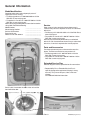
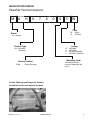
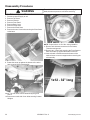
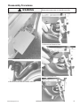
1
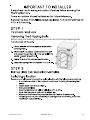
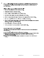
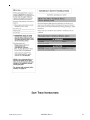
Service
This manual is to be used by qualified appliance
technicians only. Maytag does not assume any
responsibility for property damage or personal
injury for improper service procedures done by
an unqualified person.
27” Front Load
Washer
This Base Manual covers general information.
Refer to individual Technical Sheet
for information on specific models.
This manual includes, but is
not limited to the following:
MAH9700AW*
16025909
March 2005
©2005 Maytag Services
Important Notices for Servicers and Consumers
Maytag will not be responsible for personal injury or property damage from improper service procedures. Pride and
workmanship go into every product to provide our customers with quality products. It is possible, however, that
during its lifetime a product may require service. Products should be serviced only by a qualified service technician
who is familiar with the safety procedures required in the repair and who is equipped with the proper tools, parts,
testing instruments and the appropriate service information. IT IS THE TECHNICIANS RESPONSIBLITY TO
REVIEW ALL APPROPRIATE SERVICE INFORMATION BEFORE BEGINNING REPAIRS.
!
WARNING
To avoid risk of severe personal injury or death, disconnect power before working/servicing on appliance to avoid
electrical shock.
To locate an authorized servicer, please consult your telephone book or the dealer from whom you purchased this
product. For further assistance, please contact:
Customer Service Support Center
CAIR Center
Web Site
Telephone Number
WWW.MAYTAG.COM ............................................. 1-800-688-9900
CAIR Center in Canada ........................................... 1-800-688-2002
Recognize Safety Symbols, Words, and Labels
! DANGER
DANGER—Immediate hazards which WILL result in severe personal injury or death.
!
WARNING
WARNING—Hazards or unsafe practices which COULD result in severe personal injury or death.
!
CAUTION
CAUTION—Hazards or unsafe practices which COULD result in minor personal injury, product or property
damage.
2
16025909 Rev. 0
©2005 Maytag Services
Important Information .................................................... 2
Important Safety Information ......................................... 4
General Information
Model Identification .................................................... 8
Serial Label Location ................................................. 8
Model Nomenclature .................................................. 9
Troubleshooting
Troubleshooting General Symptoms ......................... 10
Component Testing Information
Component Testing Information ................................. 21
Disassembly Procedures
Top Removal ............................................................. 26
Water Level Sensor .................................................. 26
Reactor Removal ...................................................... 27
EMI Filter .................................................................. 27
Water Valve Removal ................................................ 28
Dispenser Removal ................................................... 28
Console Removal ...................................................... 29
Door Removal ........................................................... 29
Front Panel Removal ................................................. 31
Boot Removal ........................................................... 32
Heater Removal ......................................................... 32
Motor Removal .......................................................... 33
Drain Pump Removal ................................................. 35
Outer Tub/Spinner Removal ...................................... 36
Appendix A
Installation Instructions ............................................. 41
Appendix B
Use And Care ........................................................... 49
©2005 Maytag Services
16025909 Rev. 0
3
Important Safety Information
To reduce the risk of fire, electric shock, serious injury
or death to persons when using your washer, follow
these basic precautions:
• Read all instructions before using the washer.
• Refer to the Grounding Instructions in the Installation
Manual for the proper grounding of the washer.
• Do not wash articles that have been previously
cleaned in, washed in, soaked in, or spotted with
gasoline, dry-cleaning solvents, or other flammable or
explosive substances as they give off vapors that
could ignite or explode.
• Do not add gasoline, dry-cleaning solvents, or other
flammable or explosive substances to the wash
water. These substances give off vapors that could
ignite or explode.
• Under certain conditions, hydrogen gas may be
produced in a hot water system that has not been
used for two weeks or more. Hydrogen gas is
explosive. If the hot water system has not been used
for such a period, before using a washing machine or
combination washer-dryer, turn on all hot water
faucets and let the water flow from each for several
minutes. This will release any accumulated hydrogen
gas. The gas is flammable, do not smoke or use an
open flame during this time.
• Do not allow children to play on or in the washer.
Close supervision of children is necessary when the
washer is used near children. This is a safety rule for
all appliances.
• Before the washer is removed from service or
discarded, remove the lid to the washing
compartment.
• Do not reach into the washer if the wash tub is
moving.
• Do not install or store the washer where it will be
exposed to water and/or weather.
• Do not tamper with the controls.
• Do not repair or replace any part of the washer, or
attempt any servicing unless specifically
recommended in the User-Maintenance instructions
or in published user-repair instructions that you
understand and have the skills to carry out.
• To reduce the risk of an electric shock or fire, do not
use an extension cord or an adapter to connect the
washer to the electrical power source.
• Use your washer only for its intended purpose,
washing clothes.
• Always disconnect the washer from electrical supply
before attempting any service. Disconnect the power
cord by grasping the plug, not the cord.
• Install the washer according to the Installation
Instructions. All connections for water, drain,
electrical power and grounding must comply with
local codes and be made by licensed personnel
4
16025909
•
•
•
•
•
•
•
•
•
•
•
•
when required. Do not do it yourself unless you know
how!
To reduce the risk of fire, clothes which have traces
of any flammable substances such as vegetable oil,
cooking oil, machine oil, flammable chemicals,
thinner, etc. or anything containing wax or chemicals
such as in mops and cleaning cloths, must not be
put into the washer. These flammable substances
may cause the fabric to catch on fire by itself.
Do not use fabric softeners or products to eliminate
static unless recommended by the manufacturer of
the fabric softener or product.
Keep your washer in good condition. Bumping or
dropping the washer can damage safety features. If
this occurs, have your washer checked by a qualified
service person.
Replace worn power cords and/or loose plugs.
Be sure water connections have a shut-off valve and
that fill hose connections are tight. Close the shut-off
valves at the end of each wash day.
Loading lid must be closed any time the washer is in
operational fill, tumble, or spin. Do not attempt to
bypass the loading lid switch by permitting the
washer to operate with the loading lid open.
Always read and follow manufacturer’s instructions
on packages of laundry and cleaning aids. Heed all
warnings or precautions. To reduce the risk of
poisoning or chemical burns, keep them out of the
reach of children at all times (preferably in a locked
cabinet).
Always follow the fabric care instructions supplied by
the garment manufacturer.
Never operate the washer with any guards and/or
panels removed.
Do not operate the washer with missing or broken
parts.
Do not bypass any safety devices.
Failure to install, maintain, and/or operate this
washer according to the manufacturer’s instructions
may result in conditions which can produce bodily
injury and/or property damage.
NOTE: The Warnings and Important Safety Instructions
appearing in this manual are not meant to cover
all possible conditions and situations that may
occur. Common sense, caution and care must
be exercised when installing, maintaining, or
operating the washer.
Always contact your dealer, distributor, service agent or
the manufacturer about any problems or conditions you
do not understand.
Rev. 0
©2005Maytag Services
Important Safety Information
To avoid personal injury or death from improper servicing,
make sure you read and understand the descriptions and
meaning of various safety symbols, words and labels
used in this manual, before attempting any procedures
described in the manual. Failure to understand and
comply with safety information may result in severe
personal injury or death.
General Information
This Service Manual describes the operation,
disassembly, troubleshooting, and repair of the Compact
washer. It is intended for use by authorized technicians
who troubleshoot and repair these units.
NOTE: It is assumed that users of this manual are
familiar with the use of tools and equipment used
to troubleshoot and repair electrical, and
mechanical systems; and understand the
terminology used to describe and discuss them.
Related Publications
This is a base service manual, covering a range of similar
models. It is intended to be used in conjunction with the
Parts Manual and Technical Sheet covering the specific
model being serviced.
Electrical Service Information
For the safety of our customers and the Service
Technician ALL appliances have a three–prong power cord
and MUST be connected to a properly polarized AND
grounded wall outlet.
This information was written for those who do not
understand grounding and polarization of a wall outlet.
A 120 volt wall outlet must always be wired as shown
below.
Ground
©2005Maytag Services
To reduce the risk of fire, electric shock, serious injury
or death, all wiring and grounding must conform with
the latest edition of the National Electric Code, ANSI/
NFPA 70, or the Canadian Electrical Code, CSA
C22.1, and such local regulations as might apply. It is
the customer’s responsibility to have the wiring and
fuses checked by a qualified electrician to make sure
your home has adequate electrical power to operate
the washer.
To avoid risk of personal injury or death due to
electrical shock:
•
•
•
•
•
•
•
•
•
Observe all local codes and ordinances.
Disconnect electrical power to unit before servicing.
Ground appliance properly.
Check with a qualified electrician if you are not sure
this appliance is properly grounded.
DO NOT ground to gas line.
DO NOT ground to cold water pipe if pipe is
interrupted by plastic, nonmetallic gaskets, or other
insulating (nonconducting) materials.
DO NOT modify plug on power cord. If plug does not
fit electrical outlet, have proper outlet installed
by qualified electrician.
DO NOT have a fuse in the neutral or ground circuit.
A fuse in the neutral or ground circuit could result in
an electrical shock.
DO NOT use an extension cord with this appliance.
DO NOT use an adapter plug with this appliance.
DO NOT pinch power cord.
Neutral
L1
Round
grounding
prong
In the event of an electrical short circuit, a ground wire
reduces the risk of electric shock by providing an escape
wire for the electric current.
Standard accepted color coding for ground wires is green
or green with a yellow stripe.
Grounding wires and wires colored like grounding wires
are NOT to be used as current carrying conductors.
•
•
Proper Grounding and Polarization of
120 Volts Wall Outlets
Neutral
side
About Ground Wires
115±12
V.A.C.
0
V.A.C.
115±12
V.A.C.
16025909 Rev. 0
5
Important Safety Information
Explanation
Polarization–This means that the larger slot must be
neutral and the small slot must be at line voltage.
Mispolarized–The outlet is incorrectly wired so that the
larger slot is at line voltage and the smaller slot is neutral.
Grounded–This means the round hole connection is connected to earth ground through a connection to the main
power panel.
Ungrounded–The round hole connection is not complete to
earth ground and/or the main power panel.
Grounding Instructions
• To avoid the risk of electrical shock or death, do not
alter the plug.
• Do not remove grounding prong when installing
grounded appliance in a home that does not have
three wire grounding receptacle. Under no condition
is grounding prong to be cut off or removed. It is the
personal responsibility of the consumer to contact a
qualified electrician and have properly grounded three
prong wall receptacle installed in accordance with
appropriate electrical codes.
• To avoid the risk of electrical shock or death, this
equipment must be grounded.
This equipment MUST be grounded. In the event of an
electrical short circuit, grounding reduces the risk of
electric shock by providing an escape wire for the electric
current. This unit is equipped with a cord having a
grounding wire with a grounding plug. The plug must be
plugged into an outlet that is properly installed and
grounded.
Consult a qualified electrician or technician if grounding
instructions are not completely understood, or if doubt
exists as to whether the equipment is properly grounded.
Do not use an extension cord. If the product power cord
is too short, have a qualified electrician install a three-slot
receptacle. This unit should be plugged into a separate 60
hertz circuit with the electrical rating as shown in the
appropriate drawing. Models operate with a supply voltage
of 120 Volts.
6
16025909 Rev. 0
©2005Maytag Services
Important Safety Information
©2005Maytag Services
16025909 Rev. 0
7
General Information
Model Identification
Complete registration card and promptly return. If
registration card is missing:
• For Maytag product call 1-800-688-9900 or visit the
Web Site at www.maytag.com
• For product in Canada call 1-866-587-2002 or visit the
Web Site at www.maytag.com.
When contacting provide product information located on
rating label. Record the following:
Model Number:
___________________
Manufacturing Number:
___________________
Serial or S/N Number:
___________________
Date of purchase:
___________________
Dealer’s name and address:
___________________
Service
Keep a copy of sales receipt for future reference or in
case warranty service is required. To locate an authorized
technician:
• For Maytag call 1-800-462-9824 or visit the Web Site at
www.maytag.com.
• For product in Canada call 1-866-587-2002 or visit the
Web Site at www.maytag.com.
Warranty service must be performed by an authorized
technician. We also recommend contacting an authorized
technician, if service is required after warranty expires.
Parts and Accessories
Purchase replacement parts and accessories over the
phone. To order accessories for your product call:
• For Maytag product call 1-800-462-9824 or visit the
Web Site at www.maytag.com.
• For product in Canada call 1-866-587-2002 or visit the
Web Site at www.maytag.com.
Extended Service Plan
We offer long-term service protection for this new washer.
• Dependability PlusTM Extended Service Plan is
specially designed to supplement Maytag’s strong
warranty. This plan covers parts, labor, and travel
charges.
Call 1-800-925-2020 for information.
Serial Label is locatedon the back of the unit and the
front behind the door.
8
16025909 Rev. 0
©2005Maytag Services
General Information
Washer Nomenclature
M
A
H
9
7
0
0
A
Y
W
Color
Brand
W
M
M= Maytag
Product Type
Listing
W
Y
Z
Y
AH= Automatic
Horizontal
120V-60hz
240V-60hz
Canada 240V-60hz
220-240 V / 50-60 Hz
Marketing Code
Feature Content
9700
White
Platinum
This identifies which
version of production the
unit is.
Feature Package
Trouble Shooting and Diagnostic Guide is
located behind the unit taped to the back.
©2005Maytag Services
16025909 Rev. 0
9
Troubleshooting Procedures
!
WARNING
To avoid risk of electrical shock, personal injury or death, disconnect power to unit before servicing, unless testing
requires power.
Place washer into Service Mode and check for diagnostic codes. See Technical Data Sheet taped to rear
panel.
CN9 pins 1 & 3 = 11.6ohms ±7%,
Will Not Start
Pins 1 & 2 = 11.6ohms ±7%,
• Plug cord into live electrical outlet. Check for
Pins 2 & 3 = 11.6 ohms ±7%
proper voltage.
• Faulty Main Control Board.
• Check fuse or reset circuit breaker.
• Faulty motor.
• Push any key to turn on the clothes washer.
Push the rotary selector knob to start the
Will Not Spin
washer.
• Check to make sure the door is fully closed.
• Close door and push the rotary selector knob
to start the clothes washer.
• Check for water left inside the washer. If
present, see Will Not Drain.
• Check to see if the washer is in a pause or
soak period in the cycle. Wait briefly for
• Perform Board Output Test or Quick Spin
machine to start. (If washer is in suds period,
Test. (Before test, make sure that the tumbler
“SUDs” will display instead of remaining time.
is empty.) If it doesn’t tumble after the test
above, check unbalanced load scenario, Main
• Check for restricted drain system. During an
electrical drain problem, “nd” error will occur
Control Board, and motor.
after 15 minutes.
• Check for loose connections at Machine
Control Board, Pressure Switch, Motor, Tach
• Check water supply is working.
Harness and Motor Control. (CN8, CN9, CN3)
• Check water valve connections are good.
Refer to the component testing procedure.
• Check the line filter and water valve filter.
• Check motor winding resistance
• Check the machine control board terminal
CN9 pins 1 & 3=11.6ohms ±7%,
connections CN5, CN6 for good connections.
Pins 1 & 2=11.6ohms ±7%,
• Replace console control board.
Pins 2 & 3=11.6ohms. ±7%.
Leaking
• Check dispenser hose to outer tub for
obstructions or restrictions.
• Make sure inlet hose connections are not
leaking. Check for rubber gasket damage due
to over-tightening of faucet couplers.
• Check standpipe for leak. Wrap a dry rag
around the standpipe opening. If rag becomes
wet, leak is fault of home plumbing. Be sure
the standpipe is capable of accepting the
incoming flow of water from the washer.
• Make sure end of drain hose is correctly
inserted and secured to drain standpipe.
• Check internal hose connections (fill, drain
systems, dispenser hoses & clamps).
• Check rubber boot. Remove, reposition and
reinstall, if necessary.
• Check for possible kinked dispenser to outer
tub hose. Hot water pressurization may force
door open.
No Water Fill
• Test water fill. Perform Board Output Test.
• Check to make sure water supply is turned on
fully.
• Check electrical circuit and connections at the
Water Valve, and Pressure Switch.
• Check for kinks in inlet hoses.
• Check for clogged inlet screens.
• Visually check hot, cold, bleach and softener
water valves separately for fill.
• Check for low water pressure. May be
dependent on pressure entering home.
Variations may occur due to usage in the
home at the time machine is used.
• Check for frozen pipes and hoses.
• Check resistance of Water Valve coils.
(Normal 1.18Kohms; Check resistance of
water valve coils. Check Pin #1 of CN5 and
Pin # 1,2,3,4 of CN10.
• Check for loose connections at the Pressure
Switch or on the Machine Control Board,
CN3. (Refer to the component Testing
procedure).
No Tumble
• Start normal cycle with an empty machine and
allow a fill to check tumble.
• Perform Board Output Test, or Quick Spin
Test (Before test, make sure that the tumbler
Tub Full of Suds
is empty.)
• Check for restricted drain system. See Will
• Check for loose connections at Machine
Not Drain and Will Not Spin.
Control Board, Pressure Switch, Motor, Tach
• Check for loose wire connections at Control
Harness and Motor Control. (Refer to the
component testing procedure)
• Check motor windings resistance.
10
16025909 Rev. 0
©2005 Maytag Services
Troubleshooting Procedures
!
WARNING
To avoid risk of electrical shock, personal injury or death, disconnect power to unit before servicing, unless testing
requires power.
Board and pump.
Perform Board Output Test.
Use high efficiency or low sudsing detergent
specially formulated for front load washers.
• Reduce detergent amount for that specific
load size and soil level. Towel loads have a
minimal amount of soil present and typically
create more suds.
• Run the clothes washer through another
complete cycle using the coldest water,
tablespoon of salt and no detergent.
Wet Clothes
• Very small clothes loads can cause
unbalanced loads. Add additional towels.
• Excessive suds may have been present, due
to not using High-Efficiency detergent.
Reduce amount of detergent usage.
• See Will Not Spin.
• Low Spin Speed or Drain Only was selected.
•
•
Will Not Lock
• Door not all the way closed or not properly
aligned. Possible laundry load is too large to
close door.
• Place washer into Service Mode and check
for diagnostic codes 4,18 & 22.
• Perform Board Output Test. Check door
lock system. Check the output voltage of Door
Lock Coil. If normal, change door Lock
switch, If not normal, change Main Control
Board. (Refer to the Component Testing
procedure.)
• Check electrical connections at lock switch
assembly and machine control board (CN5
and CN9). (Refer to the Component Testing
procedure.).
Will Not Unlock
• Push door closed to make sure nothing from
inside is pressing against it, which may keep it
from unlocking.
• Door locked from water level too high.
Opening door will result in water draining from
door opening.
• Check for water remaining in the tub. Check
the temperature inside the drum is higher
than 50°C/122°F. If water is present inside
drum, refer to “Will not drain”, If there is no
problem with temperature, check wiring of
Main Control Board and Door Lock Switch.
• Drain manually by removing drain hose
clamp.
• Display shows LO. Press power Off Key to
turn off the washer and unplug and reconnect
washer. Press any key to turn on the washer.
©2005 Maytag Services
•
•
•
•
If LO is displayed, Main Control Board and
Door Lock Switch should be checked.
Place washer into Service Mode and check
for diagnostic codes 4,18 & 22.
Check electrical connections at lock switch
assembly and Machine Control Board (CN10).
(Refer to the component Testing procedure.)
Perform Board Output Test. Check door
lock system for loose connections.
Perform Board Output Test. Check door
lock system. Check the output voltage of Door
Lock Coil If 120V present change door Lock
switch, If not present, change Main Control
Board. (Refer to the component Testing
procedure.)
Will Not Drain
• Check for restricted drain system.
• In cold climates check for frozen drain hose.
• Check for 120 VAC at the pump when a spin
cycle is selected.
• Check pump motor winding resistance. (14.2
±7% ohms)
• Check that the machine control correctly
senses the water level in the washer. See
Board Input Test.
• Go to Board Output Test and perform Pump
Out Test.
• Check the Machine Control Board
connections at CN10 (Pin 6) for the pump.
Should see 110-120VAC.(Refer to the
component testing procedure).
• Check tub to pump hose for twist in hose.
Wrong Water Temperature
• Check that both faucets are turned on fully.
• Make sure water heater is set to deliver a
minimum of 120°F (49°C) hot water at the
tap. Also check water heater capacity and
recovery rate.
• If the water heater is located a long distance
from washer, the water line may need to be
purged prior to starting wash cycle.
• Too Hot/Too Cold: This washer uses a
reduced amount of water, while the control
board meters the incoming flow to regulate
the actual temperature of the water in the tub.
This may appear to be significantly
warmer/cooler than expected.
• Make sure the temperature selection is
correct.
16025909 Rev. 0
11
Troubleshooting Procedures
!
WARNING
To avoid risk of electrical shock, personal injury or death, disconnect power to unit before servicing, unless testing
requires power.
•
Disconnect inlet hoses from the Water Valve
and clean the valve screens of any debris.
Noisy and/or Vibration/Walking
•
•
•
•
•
Check if the washer was properly leveled and
the locking nuts are securely tightened up
against the base frame of the washer.
Check and determine all four of the shipping
bolts and spacers have been fully removed
from the rear panel of the washer.
Check for proper load size and distribution. If
clothes load is too small, add a few towels to
balance the clothes load better.
Check the tightness of the rear pulley bolt.
Tighten if necessary.
Clean floor and bottom side of washer feet.
Check clearance. Refer to the back of
machine and Installation Instruction.
Consumer Information Codes
If the consumer observes codes on display, see table
below.
LED
Description
Diagnostic
Display
code
Rubber Feet Leaving Marks on Floor
•
•
•
•
LO
nF
FL
Use a pencil eraser to remove mark.
Walk washer into location, do not drag.
Additive Cups Full of Water
•
nd
Small amount of water in bottom of additive
cups is normal.
Remove and wash Dispenser Tray,
removable Cup, and Rinse Cap.
Level washer.
•
•
Option and Function buttons respond
differently according to each cycle.
Child Lock feature has been selected. To
disable feature press and hold Wash/Rinse
Temp and Spin Speed simultaneously until a
beep is heard.
When display shows "End", only the Power
Off button will function. Press Power Off and
make new cycle selections.
3
4
8
OE
A fault is
detected in the
water level
sensor. Data
(frequency)
shows the water
level is at or
above the
overflow level.
E
E2
Detected a key
pressed more
than 30seconds,
the key will be
assumed to be
stuck.
15
od
16025909 Rev. 0
2
Water sensor
level fault.
dc
12
1
LE
Buttons do not Respond
•
The water level
fails to drop
below the Low
Water level reset
within 15
minutes, before a
spin begins.
Door failed to
unlock after 3
attempts.
Continuous fill of
12minutes. Total
fill of 14minutes.
Door failed to
lock after3
attempts.
Never exceeded
400rpm due to
an unbalanced
load.
The door has not
been opened
after two
complete wash
cycles. Door
switch was not
seen open since
the last two final
spins.
10
17
©2005 Maytag Services
Troubleshooting Procedures
!
WARNING
To avoid risk of electrical shock, personal injury or death, disconnect power to unit before servicing, unless testing
requires power.
LED
Display
Description
Diagnostic
code
dL
Open door lock
switch with motor
running.
dS
Door switch is
read as open and
the door locked
switch is read as
locked.
22
bE
Motor tach signal
exists without
motor running.
25
tE
Abnormal
high/low temp or
ohm resistance
seen.
29
E3
Machine control
is attempting to
drive the motor
but is not seeing
any tach
response. Visual
check shows
motor is not
moving. (Locked,
Hall Sensor fault)
2E
Sr
System Relay
failure.
34
Hr
Heater Relay
failure.
36
3E
Over Current is
detected. Motor
won't turn.
3E
2E
Voltage for motor
control bus is
over specified
limit.
91
2E
Voltage for motor
control bus is
under specified
limit.
92
18
of any wash cycle without interrupting the cycle.
While in Service Mode, the technician can cancel the
current cycle, set a continuous running mode, start a
variety of special service tests and view diagnostic
displays.
Enter / Exit Service Mode
To enter Service Mode press the Chime and Extra
Rinse keys for three seconds or until the control
beeps.
NOTE: The washer must be on before Service Mode
can be entered.
The motor speed will be displayed when started
(motor not running display will be 0). The present
state of the machine will not be changed (i.e., the
current cycle in progress will not be interrupted and
only the display will change). All LED’s will be turned
off except the “Door Lock” LED. It will continue to
display the condition of the door lock.
To exit:
1) Press Chime and Extra Rinse keys for 3 seconds
again, or
2) Press Off, or
3) Unplug the machine. Pressing the Rotary Selector
knob while running a test will pause the individual
test, while remaining in Service Mode.
The following table summarizes special tests and
features available in Service Mode, along with
methods of activation and cancellation.
Access Service Tests and Diagnostic Features
while in Service Mode.
Test or Display
Press LED to
Press LED to
Cancel
Start
Service Mode
Quick Spin
Test
Press Delay
Start and
Rinse&Spin
Hold Quick
Spin Step
(holds
predefined
RPM)
Press Rotary
Selector
(during test)
Press Delay
start and
Rinse&Spin
Press Off (exits
Service Mode)
Press Rotary
Selector
(cancels hold &
resumes next
step)
Service Mode enables service personnel to verify the
operation of the washing machine and diagnose
problems. Service Mode can be entered in the middle
2
©2005 Maytag Services
1
16025909 Rev. 0
13
Troubleshooting Procedures
!
WARNING
To avoid risk of electrical shock, personal injury or death, disconnect power to unit before servicing, unless testing
requires power.
Test or Display
Test or Display
Press LED to
Start
Fast
TimeDown /
Advance
to Next
Step
#
Quick
Service
Cycle
Hold Quick
Service Cycle
Step
LED/Switch
Test
IN
Board
Input
Test
Board
Output
Test /
System Check
Press
Temperature
to start test.
Press
Temperature
during cycle to
advance.
Press
Temperature
and Soil Level
Press LED to
Start
Press LED to
Cancel
Press Power
Off
All Diagnostic
Codes
Cycle Count
No. for
Diagnostic
Code
Press Off (also
exits Service
Mode)
Press
Rinse&Spin
and Spin Only
together
Press Delay for
3 seconds (then
individual
buttons to test)
Rotate Cycle
Selector
clockwise, the
LED’s around it
will be toggled.
Rotate
counterclockwis
e, the7segment LED’s
toggle. Press
Rotary Cycle
Selector, all of
the LED’s
around the
Rotary Cycle
Selector will be
toggled.
Press Spin
Only
Press
Rinse&Spin
and Spin Only
to resume
Press Off twice
after starting
test
Press Spin
Speed
Press Off
Press Rinse&
Spin – displays
“d”
Press
Rinse&Spin
again
Clear All
Diagnostic
Codes
Display
Software
Version
Cycle Count
Rotate Cycle
Selector either
direction
Press and hold
Rotary
Selector, while
diagnostic code
is displayed
Press Delay
and Chime
together while
displaying
diagnostic
codes
Press Soil
Level. Press 2
times for
displays with
only 2 character
positions.
Press LED to
Cancel
N/A
Release Rotary
Selector
(returns to
diagnostic code
display)
Press Soil
rd
Level a 3 time
Press Chime
Quick Spin Test
While in Service Mode, press Delay and
Rinse&Spin keys to start a Quick Spin Test.
Quick Spin test steps are as follows:
• Start spinning and after reaching a
maximum spin speed.
• stay at maximum spin speed for 2
minutes and stop Quick Spin Test.
Press Spin
Only
Hold Quick Spin Step
If the Rotary Selector key is pressed during
the Quick Spin test, the machine will hold at
the next highest index speed for up to 10
minutes. At the end of 10 minutes, the
machine will resume and finish the Quick
Spin test. To cancel the Hold and allow the
Spin Test to continue, press the Delay and
Rinse&Spin keys.
Diagnostic
Code Display
(Initial)
2
14
16025909 Rev. 0
©2005 Maytag Services
Troubleshooting Procedures
!
WARNING
To avoid risk of electrical shock, personal injury or death, disconnect power to unit before servicing, unless testing
requires power.
¤
The “SC” in the display will blink as an indication of
failure, and continue blinking until the quick service
cycle test has reached the end. Any diagnostic code
logged during this test will result in failure of the test,
but will not necessarily stop the test. During the Quick
Service Cycle, pressing the Spin Speed key will
advance to the next step. Pressing
the Rinse&Spin and Spin Only
keys will suspend the machine at
the current step for up to 10 minutes or until Delay
Start and Chime are pressed again. All LED’s should
flash on and off while the system is suspended or on
hold.
Fast Time Down Test
While any test or cycle is running in
Service Mode, pressing the Temperature
key will advance the program to the next
cycle stage.
Cycle stages are located at key locations in the
machine operation. As the program is advanced it
will index as follows: The end of each fill (the
same as the beginning of a tumble session for
Wash, or Rinse); at the beginning of a drain
session; at the beginning of a spin session (at this
position, check the water level, if over reset level,
drain first before entering the spin function); at the
beginning of a fill session; at the beginning of
Bleach fill; at the beginning of Fabric Softener fill;
and every 3 minutes during the tumble sessions
(Wash, and Rinses).
LED/Switch Test
While in Service Mode, press the Delay key to start a
LED/Switch check. All the LED’s can be toggled or
slewed by pressing the key associated with the LED
or set of LED’s. All keys (including the OFF button)
must be pressed within 5 minutes for this test to pass.
“PA” will be displayed for five (5) seconds once all
keys have been pressed and the test is completed.
Following 20seconds of inactivity at any point, this test
will exit without any display. The Power Off switch
pad must be pressed twice within 30 seconds to
cancel this test.
#
Quick Service Cycle
While in Service Mode, pressing the
Temperature and Soil Level key for
3seconds will start a Quick Service Cycle.
This will be a quick check of all systems. If display
shows od then open and close door. Pressing
Spin Speed will advance to the next cycle. The
following steps are performed: Display shows
“SC”.
1. Hot water for 5 seconds and then turn off.
2. Cold water for 5 seconds and then turn off.
3. Bleach valve for 5 seconds and then turn off.
4. Dispenser softener using cold water and
bleach water for 5 seconds and then turn off.
5. Turn on Cold valves until the control detects
proper water level. During this time, tumble at
45 rpm for 5seconds in a clockwise direction,
pause for 2seconds, tumble at 45 rpm for 5
seconds in a counterclockwise direction,
pause for 2 seconds. Continue pattern until
the water level is detected. Minimum time for
this segment to be 5 seconds. After water
height is achieved, continue tumble pattern
for another 14 seconds. If the washer is
equipped, turn on heater for first 5 seconds of
this tumble pattern. Advance the washer to
next step if water is not connected to
machine.
6. Drain and spin to maximum speed. Machine
will achieve maximum speed using the safest,
fastest method.
7. Display a “PA” (Passed) continuously for 5
seconds I no diagnostic codes were logged
during the test. Washer will return to the
normal Service Mode at the end of the 10
second period.
©2005 Maytag Services
Switch
Delay Start
Chime
Extra Rinse
Soil Level
Spin Speed
Temperature
Rinse&Spin
Spin Only
Prewash
Extended Spin
Selector Knob
Selector Knob
Start Pause
Selector Knob
Power Off
IN
16025909 Rev. 0
2
Action
Press once
Press 3 times
Press once
Press 4 times
Press 5 times
Press 5 times
Press once
Press once
Press once
Press once
Rotate 1 full revolution clockwise
1 position counterclockwise
Press once
Press once
Press once
Board Input Test
• While in Service Mode, pressing the Spin
Only key will begin the Board Input Test.
This test turns on a specified output after
a key press. Pressing the Spin Only key
again cancels the test.(Display shows
15
Troubleshooting Procedures
!
WARNING
To avoid risk of electrical shock, personal injury or death, disconnect power to unit before servicing, unless testing
requires power.
in).While in Service Mode follow chart to check
respective function.
• When the “Rotary Cycle Selector” is set to
“Super Wash” and the “Rotary Cycle
Selector” is pressed, the door position will be
displayed: “OP” if open, “CL” if closed.
• When the “Rotary Cycle Selector” is set to
“Normal” and the “Rotary Cycle Selector” is
pressed, the Lock position will be displayed:
“UL” if unlocked, “LO” if locked.
• When the “Rotary Cycle Selector” is set to
“Whites ”and the “Rotary Cycle Selector” is
pressed, the High water level will be
–
–
displayed: “ 0” if below level, “ 1” if above
level. The High water level is defined as the
over flow water level.
• When the “Rotary Cycle Selector” is set to
“Wrinkle Control” and the “Rotary Cycle
Selector” is pressed, the Medium water level
will be displayed: “-0” if below level, “-1” if
above level. The Medium water level is
defined as the minimum water level needed to
turn the heater on.
• When the “Rotary Cycle Selector” is set to
“Colors” and the “Rotary Cycle Selector” is
pressed, the Low water level will be displayed:
“_0” if below level, “_1” if above level. The
Low water level is defined as the reset water
level.
• When the “Rotary Cycle Selector” is set to
“Hand Wash” and the “Rotary Cycle
Selector” is pressed, the level of Tub
unbalance will be displayed: “UC” if balanced,
“UO” if unbalanced. “U0” will be displayed
during the time when the machine is
correcting for the unbalance; e.g. slowing
down to redistribute the load or to get to a
lower spin speed. Once the situation has
been corrected (i.e. the load has begun
tumbling or the lower speed has resulted in an
acceptable amount of balance); “UC” will
once again be displayed.
• When the “Delay” switch pad is pressed, the
water temperature will be displayed in
Degrees F.
• When the “Rotary Cycle Selector” is set to
“Delicates” and the “Rotary Cycle Selector”
is pressed, the water temperature will be
displayed in degrees C (Celsius).
16
2
While in Service Mode follow chart to check
respective function.
Selection
Function
Display
Rotary cycle
Door position “OP” or “CL”
selector set to
Super Wash. Press
Rotary Selector
Knob.
Rotary cycle
Lock state
“UL” or “LO”
selector set to
Normal. Press
Rotary Selector
Knob.
–
Rotary cycle
High water
“ 0” if below
selector set to
level
–
level. “ 1” if
Whites. Press
above level.
Rotary Selector
Knob.
Rotary cycle
Medium
“—0” if below
selector set to
water level
level. “—1” if
Wrinkle Control.
above level.
Press Rotary
Selector Knob.
Rotary cycle
Low water
“_0” if below
selector set to
level
level. “_1” if
Colors. Press
above level.
Rotary Selector
Knob.
Rotary cycle
Tub balance “UC” Balanced
selector set to
“UO”
Hand Wash. Press
Unbalanced
Rotary Selector
Knob.
Press Delay switch Water
Degrees F
pad.
temperature
Rotary cycle
Water
Degrees C
selector set to
temperature
Delicates. Press
Rotary Selector
Knob.
Board Output Test
While in Service Mode, pressing the Spin
Speed key will begin the Board Output Test.
This test turns on a specified output after a
key press. Pressing the Spin Speed key again
cancels the test. Only one output can be “on” at any
time. All outputs will be turned off after five (5)
minutes of inactivity.
While in Service Mode follow to check respective
function.
• When the “Rotary Cycle Selector” is set to
“Super Wash” and the “Rotary Cycle
16025909 Rev. 0
©2005 Maytag Services
Troubleshooting Procedures
!
WARNING
To avoid risk of electrical shock, personal injury or death, disconnect power to unit before servicing, unless testing
requires power.
the “Chime” button. This output will attempt to
• Selector” button is pressed, the Main relay
unlock one time, if safe to do so.
will be toggled (either from “on” to “off” or
• Pressing the “Temperature” switch pad will
from“ off” to “on”).
lock the door and all the Temperature LED’s
• When the “Rotary Cycle Selector” is set to
will turn ON. Pressing the “Chime” button will
“Normal” and the “Rotary Cycle Selector”
unlock the door and the all the Chime LED’s
button is pressed, the hot water valve will be
will turn ON.
turned on. This output will remain on until the
• When the “Rotary Cycle Selector” is set to
“Rotary Cycle Selector” button is pressed
“Colors” and the “Rotary Cycle Selector” is
again to turn off the output. The control will
not allow the machine to fill past the High
pressed, the bleach valve and the cold water
water level.
valve will be turned on to check the fabric
softener fill. This output will remain on until
• When the “Rotary Cycle Selector” is set to
the “Rotary Cycle Selector” button is
“Wrinkle Control” and the “Rotary Cycle
pressed again to turn off the output. The
Selector” button is pressed, the cold water
control will not allow the machine to fill past
valve will be turned on. This output will remain
the High water level.
on until the “Rotary Cycle Selector” button is
• When the “Rinse & Spin” keypad is pressed,
pressed again to turn off the output. The
the Heater will be turned on if the water level
control will not allow the machine to fill past
is above the Heater Safety Level. If the water
the High water level.
level is below the Heater Safety Level, a
• When the “Rotary Cycle Selector” is set to
warning beep will be given and the heater will
“Delicates” and the “Rotary Cycle Selector”
not be turned on. The Heater output will
button is pressed, the bleach valve will be
remain on until the “Rinse & Spin” keypad is
turned on. This output will remain on until the
pressed again to turn off the output.
“Rotary Cycle Selector” button is pressed
Selection
Component
Function
again to turn off the output. The control will
not allow the machine to fill past the High
Rotary cycle selector
water level.
set to Super Wash.
On to Off or
Main Relay
Press Rotary
Off to On
• When the “Rotary Cycle Selector” is set to
Selector Knob.
“Hand Wash” and the “Rotary Cycle
st
1 press valve
Rotary cycle selector
Selector” button is pressed, the pre wash
set to Normal. Press
Hot Water
on. 2nd press
valve will be turned on. This output will remain
Rotary Selector
Valve
valve off.
on until the “Rotary Cycle Selector” button is
Knob.
pressed again to turn off the output. The
st
1 press valve
Rotary cycle selector
control will not allow the machine to fill past
nd
set to Wrinkle
on. 2 press
the High water level.
Cold Water
Control. Press
valve off.
• When the “Rotary Cycle Selector” is set to
Valve
Rotary Selector
“Quick Wash” and the “Rotary Cycle
Knob.
Selector” button is pressed, the drain pump
st
Rotary cycle selector
1 press valve
will be turned on. This output will remain on
nd
set to Delicates.
on. 2 press
until the “Rotary Cycle Selector” button is
Bleach Valve
Press Rotary
valve off.
pressed again to turn off the output.
Selector
Knob.
• Pressing the “Delay” switch pad will turn on
st
1 press valve
Rotary cycle selector
the motor and the “Delay” LED. This output
set to Hand Wash.
Pre Wash
on. 2nd press
and the LED will remain on until the “Delay”
Press Rotary
Valve
valve off.
switch pad is pressed again to turn off the
Selector Knob.
output. When activated, the machine will
tumble for 5 seconds in the CW direction,
pause for 2seconds, tumble in the CCW
direction for 5 seconds, pause for 2 seconds;
repeating this pattern until “ Delay” button is
pressed again to turn off the tumbling. Note
that all tumble speeds are assumed to be 45
rpm.
• Pressing the “Chime” switch pad will unlock
the door and turn on the all the LED’s above
©2005 Maytag Services
16025909 Rev. 0
17
Troubleshooting Procedures
!
WARNING
To avoid risk of electrical shock, personal injury or death, disconnect power to unit before servicing, unless testing
requires power.
Selection
Rotary cycle
selector set to
Quick Wash. Press
Rotary Selector
Knob.
Press Delay switch
pad
Press Chime
switch pad
Press Temperature
switch pad
Rotary cycle
selector set to
Colors. Press
Rotary Selector
Knob.
Press Rinse & Spin
switch pad
Component
Drain Pump
Motor
Door Lock
Door Lock
Bleach Valve
and Cold
Water Valve
Heater
Function
1st press
Drain Pump
on. 2nd press
Drain Pump
off.
1st press
Motor on. 2nd
press Motor
off.
1 Attempt to
unlock
Lock Door
1st press
Fabric
Softener fill.
2nd press
valves off
1st press
heater on. 2nd
press heater
off.
Display Diagnostic Codes
The diagnostic code display can be
toggled on and off from Service
Mode by pressing the Rinse&Spin
key and rotating the cycle select knob. The display will
show a “d”. Rotating the Cycle Selector knob in either
direction will cycle through the list of codes one code
at a time with no wrap. Once an initial direction is
selected by the user (either Clockwise or
Counterclockwise), subsequent movements of the
knob in the same direction will show older codes. If
the user changes direction and turns the knob in the
opposite direction, the more recent code will be
displayed. If rotation is continued to the limits of the
list, the display will remain at the top or the end of the
list. A pair of dashes “- -” will be displayed at the end
of the list of codes, when the control reaches the top,
it will again show “d”. A code generated during the
current cycle will be displayed with the Spin Indicator
LED turned “ON”. If no cycle is currently running, a
code generated during the previous cycle will be
displayed with the Spin Indicator LED turned “ON”.
Access Other Features While a diagnostic code is
displayed, if the Rotary Selector is pressed and held,
the machine will display the number of cycles since
the diagnostic code occurred. To clear the diagnostic
list press the Delay and Chime keys for 3 seconds
while viewing the list.
18
A code generated during the current cycle will be
displayed with the Spin Indicator LED turned “ON”. If
no cycle is currently running, a code generated during
the previous cycle will be displayed with the Spin
Indicator LED turned “ON”.
Cycle Count Since A Diagnostic Code
Occured/Clearing Diagnostic Codes
While a diagnostic code is displayed, if the Rotary
Selector is pressed and held, the machine will display
the number of cycles since the diagnostic code
occurred. To clear the diagnostic list press the Delay
and Chime keys for 3 seconds while viewing the list.
Diagnostic Codes
Diag. Description
Code
1
2
No Drain
The door
fails to
unlock
3
No Fill
4
The door
fails to lock
5-7
16025909 Rev. 0
Trigger
The water
level fails to
drop below
the Low
Water level
reset within
15 minutes,
before a spin
begins.
Door failed to
unlock after
3attempts
Continuous fill
of 12
minutes.
Total fill of
14minutes.
Action to be
taken
Displays "nd"
Go to "Will Not
Drain"
Troubleshooting
Section
Displays "LO" Go to
"Will Not Unlock"
Troubleshooting
Section
Displays "nF"
Go to "No Water
Fill"
Troubleshooting
Section
Door failed to Displays "FL" Go to
lock after 3 "Will not lock"
attempts
Troubleshooting
Section.
Not Used
©2005 Maytag Services
Troubleshooting Procedures
!
WARNING
To avoid risk of electrical shock, personal injury or death, disconnect power to unit before servicing, unless testing
requires power.
Diag. Description
Code
8
Trigger
Input signal
from water
level Sensor
is out of
Water level
range,
sensor fault.
Washer will
beep and
pause the
wash cycle.
9
Displays "LE"
Go to “No water fill
Troubleshooting”.
Diag. Description
Code
15
Stuck Key
17
Door switch
was not
seen open
since the last
three final
spins
18
Detected
door lock
switch open
during cycle
when not
expected.
Not Used
10
Unbalance
detected
during final
spin, which
prevented
the spinner
from
exceeding
400 rpm
E
Water level in
the machine
is believed to
be above the
overflow level.
When this
condition is
detected, the
Water
sensor level machine will
automatically
fault.
begin
pumping
water out of
the machine
until it falls
below the
overflow level.
11
Action to be
taken
Will not
remember
machine
settings
Never
exceeded
400rpm due
to an
unbalance
load.
Difficulty in
reading
memory
12-14
©2005 Maytag Services
LED – Will display
“dc”
Go to "Wet Clothes
"Troubleshooting
Section"
First check to see
that water valve is
not stuck. If water
valve is OK, check
water level sensor
Go to "Clear
diagnostic codes"
Disconnect and
reconnect the
washer power cord
at power supply
outlet.
If condition still
exists, replace
machine control
board.
Trigger
Action to be
taken
Display "E2". Go to
A key is
sensed to be "Membrane Pad
pressed more
Check" Check
than 30
connection of
seconds, the keypad to control
key will be
board. Replace
assumed to
LED Board if
be stuck
necessary.
The door has
not been
opened after
two complete
Will display "od" If
wash cycles.
door open sensing,
Door switch
will cleared.
was not seen
open since
the last two
final spins
Check for loose
wire connections
Clear the diagnostic
code and recheck;
Open door if reoccurs, perform
lock switch Diagnostic
with motor Motor/Machine
running.
Control Board test
Check for faulty
motor relay on the
machine control
board.
19-21
Not Used
22
Door switch is
Door switch
detected open Go to "Door Lock
detected
and the door
Test"
open during
locked switch Troubleshooting
cycle (when
is read as
Section
not paused).
locked.
23-24
Not Used
Not Used
16025909 Rev. 0
19
Troubleshooting Procedures
!
WARNING
To avoid risk of electrical shock, personal injury or death, disconnect power to unit before servicing, unless testing
requires power.
Diag. Description
Code
25
Sump
thermistor
failure
(Optional)
20
Abnormal
high/low temp
or ohm
resistance
seen
Displays " bE".
Replace Machine
Control Board.
2E
Motor Drive
failure
(Locked, Hall
sensor fault)
34
System
Relay failure
3E
40-49
Displays " tE".
- Loose or pinched
wires
- Bad sump
thermistor
Not Used
Machine
control is
attempting to
drive the
motor but is
not seeing
any tach
response.
Visual check
shows motor
is not moving.
Machine
control does
not see relay
open when it
should.
Diag. Description
Code
36
Not Used
30-33
35
Action to be
taken
Tach signal
exists without
torque
Motor tach
signal exists command or
when not
without
expected
motor
(Abnormal
running.
condition
only).
26-28
29
Trigger
Display “E3”
Evaluate wire
harness for loose or
unhooked
connections. If
machine has
separate motor
control, perform self
diagnostic motor
test. See “Board
Output Test”
Display "Sr".
Replace machine
control board.
Trigger
Action to be
taken
Heater Relay
Display "Hr".
Heater relay
Check signal Replace Machine
failure.
not sensed.
Control Board.
Displays
Over Current
"3E".Check the
Motor failure
is detected. motor windings, the
(Over
Motor won't
speed sensor,
current)
turn.
wiring connections,
or Control Board.
Not Used
Voltage for
Display
Voltage for
motor control
motor control
"2E".Replace
bus is over
91
bus is over
Machine Control
specified
limit
Board.
limit
Display
Voltage for
Voltage for
motor control motor control
"2E".Replace
92
bus is under
specified
Machine Control
specified limit
limit
Board.
Exit Service Mode
To exit:
1) Press Chime and Extra Rinse keys for
3seconds again, or
2) Press Off, or
3) Unplug the machine. After five (5) minutes of
inactivity (user key presses) in Service Mode,
the machine will exit the Service Mode and
resume normal operations. Pressing the Off
key will completely exit Service Mode. If a
cycle is running, cancel the cycle. Pressing
the Rotary Selector knob while running a test
will pause the individual test, while remaining
in Service Mode. A power loss during Service
Mode will cancel this mode.
Not Used
16025909 Rev. 0
©2005 Maytag Services
Component Testing Information
!
WARNING
To avoid risk of electrical shock, personal injury or death, disconnect power to unit before servicing, unless testing
requires power.
Illustration
Component
Thermistor
Door Switch
Water Sensor
Sump Sensor
Motor
Drain Pump
Water Valves
Test Procedure
Unplug harness connector and test
from wire insertion side.
Pin #6 and Pin #3 of CN3
Unplug harness connector and test
from wire insertion side.
AC Power
Reactor
©2005 Maytag Services
13000 ohms @ 70F (2.5V DC)
Pin #7 of CN5 and Pin #3 of CN9
Pin #8 of CN5 and Pin #3 of CN9
60 ohms
60 ohms
Check voltage at Pin #6 and Pin #7 of
CN3.
Reset water level = 2.5V DC, 25.8 KHz
Check voltage at Pin #6 and Pin #8 of
CN3.
Reset water level = 2.5V DC, 25.8 KHz
Check voltage at Pin #4 and Pin #2 of
CN8.
0V DC or 3.75V
Check voltage at Pin #4 and Pin #3 of
CN8.
Unplug harness connector and test
from wire insertion side.
0V DC or 3.75V
Pin #1 and Pin #2 of CN9
Pin #1 and Pin #3 of CN9
Pin #2 and Pin #3 of CN9
11.6 ohms
11.6 ohms
11.6 ohms
During drain check voltage at Pin #1 of
CN5 and Pin #6 of CN10
120V AC
Unplug harness connector and test
from wire insertion side.
(Hot valve) Pin #2 of CN5 and Pin #2
of CN6
(Pre valve) Pin #3 of CN5 and Pin #2
of CN6
(Bleach valve) Pin #4 of CN5 and Pin
#2 of CN6
(Main valve) Pin #1 of CN5 and Pin #2
of CN6
Heater Relay
Results
During water heat check voltage at Pin
#1 of CN5 and Pin #2 of RY9
Check voltage at Pin #1 and Pin #3 of
CN5
Check voltage at Pin #1 of CN5 and
Pin #1 of CN6
Unplug harness connector and test
from wire insertion side.
16025909 Rev. 0
1100 ohms
1100 ohms
1100 ohms
1100 ohms
120V AC
120V AC
120V AC
Less than 1 ohm
21
Component Testing Information
!
WARNING
To avoid risk of electrical shock, personal injury or death, disconnect power to unit before servicing, unless testing
requires power.
9
1
CN3
3
CN6
4
1
8
5
CN8
CN10
4
1
CN9
3
CN7
1
RY9
1
1
2
1
1
1
9
2
4
1
8
4
3
3
2
1
1
ATC Control
When ATC cold wash is selected, the Heater turns on if
the water temperature in the tub is below 60 degrees F.
The heater turns off when the water temperature is above
70 degrees F or time has expired for the wash cycle. The
cycle time will not be extended to reach the desired
temperature.
When hot wash is selected, the heater will turn on if the
water temperature in the tub is below 120 degrees F. The
heater turns off when the water temperature is above 130
degrees F. or or time has expired for the wash cycle. The
cycle time will not be extended to reach the desired
temperature.
When ATC warm wash is selected, the heater turns on if
the water temperature in the tub is below 95 degrees F.
The heater will turn off when the water temperature is
above 105 degrees F or time has expired for the wash
cycle. The cycle time will not be extended to reach the
desired temperature.
22
16025909
When the Sanitary Cycle is selected, the heater turns on
if the water temperature in the tub is below 141 degrees
F. The heater turns off when the water temperature is
above 151 degrees F. The wash cycle will be extended to
achieve the temperature of 151 degrees F.
Rev. 0
©2005 Maytag Services
Component Testing Information
Note: The heater will not turn on more than once in a
wash cycle (no reheating).
!
WARNING
To avoid risk of electrical shock, personal injury or death, disconnect power to unit before servicing, unless testing
requires power.
Water flow through dispenser during Wash fill
WASH
DRAIN
©2005 Maytag Services
FILL /
Rotation of
Spinner
(HEATING)
WASHING
16025909 Rev. 0
COOLING /
DISENTANGLE
SUB
TOTAL
23
Component Testing Information
!
WARNING
To avoid risk of electrical shock, personal injury or death, disconnect power to unit before servicing, unless testing
requires power.
Water flow through dispenser during Rinse 1 fill
RINSE 1
DRAIN
24
MIDTERM
SPIN
FILL /
Rotation of
Spinner
RINSE
16025909 Rev. 0
DISENTANGLE
/ FILLING TO
REMOVE
SUDS
SUB
TOTAL
©2005 Maytag Services
Component Testing Information
!
WARNING
To avoid risk of electrical shock, personal injury or death, disconnect power to unit before servicing, unless testing
requires power.
Water flow through dispenser during Rinse 2 fill
RINSE 2
DRAIN
MIDTERM
SPIN
©2005 Maytag Services
FILL /
Rotation of
Spinner
RINSE
16025909 Rev. 0
DISENTANGLE
/ FILLING TO
REMOVE SUDS
SUB
TOTAL
25
Disassembly Procedures
!
To avoid risk of electrical shock, personal injury or
death; disconnect power to unit before servicing.
WARNING
Top Removal
1. Disconnect power supply to unit.
2. Remove 2 10mm screws from washer back.
3. Slide Top Cover towards the rear to clear the screw
head from flange on the bottom side of the Top
Cover.
Water Level Sensor Removal
1.
2.
3.
4.
5.
26
Disconnect power supply to unit.
Remove Top Cover.
Remove harness plug.
Remove Pressure Hose.
Remove single attachment screw.
16025909 Rev. 0
©2005 Maytag Services
Disassembly Procedures
!
To avoid risk of electrical shock, personal injury or
death; disconnect power to unit before servicing.
WARNING
NOTE: The reactor coil is wired in series with line 1
internally in the Control Board. An open coil or
loose electrical connection would result in a
“dead” board complaint. A resistance check
across the coil leads should indicate less than 1
ohm.
EMI Filter Removal
1. Disconnect power supply to unit.
2. Remove Top Cover.
3. Loosen 13mm acorn nut and slide EMI Filter out of
bracket.
Reactor Removal
1.
2.
3.
4.
Disconnect power supply to unit.
Remove Top Cover.
Remove single attachment screw on cross brace.
Twist Reactor counterclockwise to remove.
NOTE: Mark the wire locations on the EMI before
removing the terminals.
©2005 Maytag Services
16025909 Rev. 0
27
Disassembly Procedures
!
To avoid risk of electrical shock, personal injury or
death; disconnect power to unit before servicing.
WARNING
Water Valve Removal
1. Disconnect power supply to unit.
2. Remove Top Cover.
3. Remove two screws each hot and 3 valve combo cold
valve.
Combo Cold Valve
Hot Valve
4. Remove hose clamps and hoses.
3. Remove Top Cover.
4. Remove clamps and hoses from dispenser.
NOTE: The hose circuitry is marked on the Dispenser
top.
Dispenser Removal
1. Disconnect power supply to unit.
2. Depress the release tab and slide drawer from
washer.
Pre
Wash
Main
Hot
Bleach
Main
Cold
NOTE: The hose circuitry is marked on the Dispenser
top.
5. Remove attachment screws and lift dipenser to
expose fill hose.
28
16025909 Rev. 0
©2005 Maytag Services
Disassembly Procedures
!
WARNING
To avoid risk of electrical shock, personal injury or
death; disconnect power to unit before servicing.
5. Roll Console down and lift away from washer.
6. Remove Reactor wire harness from wire clip.
7. Remove Reactor wire harness connector from the
PCB Board.
8. Remove five screws from PCB Housing to access the
LED Circuit Board.
6. Remove fill hose clamp and hose.
Door Removal
1. Disconnect power supply to unit.
2. Remove four screws to remove door from Front
Panel.
Console Removal
1.
2.
3.
4.
Disconnect power supply to unit.
Remove Top Cover.
Remove Dispenser Drawer.
Remove five screws attaching Console.
©2005 Maytag Services
16025909 Rev. 0
29
Disassembly Procedures
!
To avoid risk of electrical shock, personal injury or
death; disconnect power to unit before servicing.
WARNING
6. Remove the glass retainer.
3. Remove hinge retainer plate.
7. Remove glass.
4. Remove door from hinge posts.
8. Remove external viewing window.
5. Remove Screws around the perimeter of the glass
retainer.
26
16025909 Rev. 0
©2005 Maytag Services
Disassembly Procedures
!
To avoid risk of electrical shock, personal injury or
death; disconnect power to unit before servicing.
WARNING
Front Panel Removal
1.
2.
3.
4.
Disconnect power supply to unit.
Remove Top Cover.
Remove Console.
Open door and remove Boot Retainer Clamp. Expand
the Boot Clamp Spring located at the 6 o’clock
position.
6. Remove four screws attaching the front to the
cabinet.
5. Pull the boot from the lip formed into the front
opening.
©2005 Maytag Services
7. Disconnect the wire connectors to the Door Lock.
16025909 Rev. 0
31
Disassembly Procedures
!
WARNING
8. Lift Front Panel from bottom brackets.
To avoid risk of electrical shock, personal injury or
death; disconnect power to unit before servicing.
NOTE: When installing the boot align the index tabs on
the boot with the screws on either side of the Fill
Tube.
Heater Removal
1.
2.
3.
4.
5.
Disconnect power supply to unit.
Remove Top Cover.
Remove Console.
Remove Front Panel.
Remove Thermistor and Heater wiring connectors.
Boot Removal
1.
2.
3.
4.
5.
Disconnect power supply to unit.
Remove Top Cover.
Remove Console.
Remove Front Panel.
Loosen boot clamp at the 12 o’clock position.
6. Loosen 10mm nut on Heater and remove Heater
Element.
NOTE: Install Heater Element on top of metal bracket.
32
16025909 Rev. 0
©2005 Maytag Services
Disassembly Procedures
!
To avoid risk of electrical shock, personal injury or
death; disconnect power to unit before servicing.
WARNING
Motor Removal
1. Disconnect power supply to unit.
2. Remove two screws attaching Back Cover and slide
cover up and lift bottom edge out of retaining slots.
4. Rotate the Spinner to locate a slot. Insert a rubber
handled tool or equivelent object to lock the Spinner
while removing the Motor nut.
3. Remove either vent tube from the outer Tub.
©2005 Maytag Services
16025909 Rev. 0
33
Disassembly Procedures
!
To avoid risk of electrical shock, personal injury or
death; disconnect power to unit before servicing.
WARNING
5. Remove 19mm nut .
7. Depress and release latch to remove motor wiring
connectors.
NOTE: When reinstalling Motor torqe nut to 32-47 ft. lbs.
8. Remove the six 10mm bolts securing stator coil to the
tub.
6. Grasp the Rotor at 3 and 9 o’clock while pulling Rotor
from shaft.
CAUTION: The rotor contains powerful magnets. Use
caution during handeling and installation. DO
NOT place fingers between rotor and
windings during installation.
NOTE: There are alignment pins for the Stator
reinstallation. Use caution during removal and
installtion, the stastor will not hang from the
alignment pins. Start a screw while supporting
the Stator with the other hand.
7. Depress and release latch to remove motor wiring
connectors.
34
16025909 Rev. 0
©2005 Maytag Services
Disassembly Procedures
!
WARNING
To avoid risk of electrical shock, personal injury or
death; disconnect power to unit before servicing.
5. Remove wiring connector.
Drain Pump Removal
1.
2.
3.
4.
Disconnect power supply to unit.
Remove Back Cover.
Remove clamp and Drain Hose.
Remove clamp and Pump Hose.
6. Remove three 13mm bolts securing Drain Pump to
base.
7. Remove screw securing Drain Pump to bracket.
Twist Drain Pump clockwise to remove.
©2005 Maytag Services
16025909 Rev. 0
35
Disassembly Procedures
!
To avoid risk of electrical shock, personal injury or
death; disconnect power to unit before servicing.
WARNING
Outer Tub and Spinner Removal
1.
2.
3.
4.
5.
6.
7.
8.
Disconnect power supply to unit.
Remove Top Cover.
Remove Console.
Remove Front Panel.
Remove Back Cover.
Remove Pump Hose.
Remove the Drain Hose
Remove the two 13mm bolts securing the Rear Struts
to the base.
NOTE: Torque bolts to 11-22 ft lbs. during installtion.
11. Remove wire harness connectors for the heater,
Themistor and ground.
12.Remove two 13mm bolts securing the Front Struts to
base and rotate up against the bottom of the tub.
13.Insert a board or boards across the bottom of the
washer frame to use as a support when removing the
tub assembly.
9. Rotate the struts up against the bottom of the tub to
ease removal of the tub assembly.
1x12 - 32” long
NOTE: The rear struts can be identified by the green
sleeve.
10.Remove two each side 13mm bolts securing Counter
Weights.
36
16025909 Rev. 0
©2005 Maytag Services
Disassembly Procedures
!
To avoid risk of electrical shock, personal injury or
death; disconnect power to unit before servicing.
WARNING
16. Remove the Pressure Hose.
14.Remove fill hose.
17. Remove ground wire.
15.Remove Pressure Switch harness connector.
©2005 Maytag Services
16025909 Rev. 0
37
Disassembly Procedures
!
To avoid risk of electrical shock, personal injury or
death; disconnect power to unit before servicing.
WARNING
18.Remove left and right Vent Hoses.
19.Lift Suspension Spring from keeper in cabinet.
Repeat for the opposite side and let Outer Tub rest
on support board.
21.Remove remaining screws securing Back Guard to
cabinet.
22.Grasp the front and rear of the tub and slide out. Use
a blanket or rug to protect the floor
20.Remove two screws securing Center Brace to Back
Guard.
38
16025909 Rev. 0
©2005 Maytag Services
Disassembly Procedures
!
To avoid risk of electrical shock, personal injury or
death; disconnect power to unit before servicing.
WARNING
NOTE: Torque tub bolts to 6-11 ft. lbs.
25. Separate the front and rear halves of the Outer Tub.
23.Set the tub on the floor. Position 4" wood blocks or
equivalent around the spinner shaft. Roll the tub to
the upright position and rest it on the blocks.
.
24.Remove the 10mm screws around the perimeter of
the tub.
©2005 Maytag Services
26. Tub Gasket can be replaced after tub halves are split.
16025909 Rev. 0
39
Disassembly Procedures
!
WARNING
To avoid risk of electrical shock, personal injury or
death; disconnect power to unit before servicing.
28.Remove screw and release tab to remove Baffles
27.Lift Spinner to access Wave Washer.
40
16025909 Rev. 0
©2005 Maytag Services
Appendix A
©2005 Maytag Services
16025909 Rev. 0
41
DC68-02032B
101504
42
16025909 Rev. 0
©2005 Maytag Services
©2005 Maytag Services
16025909 Rev. 0
43
! WA RNING
44
16025909 Rev. 0
©2005 Maytag Services
To Avoid The Possibility
•
•
Of Water Damage:
Have Water Faucets Easily Accessible
Turn Off Faucets When Washer Is Not In Use.
DRAIN FACILITY
Recommendedheight of the standpipe is 18”. The drain hose must be routed through the drain hose clip to
the standpipe. Standpipe must be large enough to acceptthe outside diameter of the drain hose. The drain
hose is attachedat the factory.
FLOORING
For best performancethe washer must be installed on a solidly constructed floor. Wood floors may need to
be reinforced to minimize vibration and/or unbalancedload situations. Carpeting and soft tile surfaces are
contributing factors in vibration and/or tendency for a washer to move slightly during the spin cycle. Never
install the washer on a platform or weakly supported structure.
LOCATION
CONSIDERATIONS
It is recommendedthe washer never be installed in areas where water may freeze since the washer will
always maintain some water in the water valve, pump and hose areas. This can cause damageto belts,
pump, hoses and other components.Operating temperature should be above 60°F.
ALCOVE OR CLOSET
INSTALLATION
MINIMUM CLEARANCES FOR CLOSET AND ALCOVE INSTALLATIONS:
Sides – 0 in / 0 mm Rear – 1 in / 25 mm
Top – 2 in / 51 mm Closet Front – 0 in / 0 mm
The closet front must have a total unobstructed air opening of 72 in 2. / 465 cm2 minimum, if both washer and
dryer are installed together. A louvered door with equivalent air opening is acceptable.Washer alone does
not require specific air opening.
©2005 Maytag Services
16025909 Rev. 0
45
46
16025909 Rev. 0
©2005 Maytag Services
Before using the washing machine, you must remove the four shipping bolts
©2005 Maytag Services
16025909 Rev. 0
47
48
16025909 Rev. 0
©2005 Maytag Services
Appendix B
©2005 Maytag Services
16025909 Rev. 0
49
50
16025909 Rev. 0
©2005 Maytag Services
©2005 Maytag Services
16025909 Rev. 0
51
52
16025909 Rev. 0
©2005 Maytag Services
©2005 Maytag Services
16025909 Rev. 0
53
54
16025909 Rev. 0
©2005 Maytag Services
©2005 Maytag Services
16025909 Rev. 0
55
56
16025909 Rev. 0
©2005 Maytag Services
©2005 Maytag Services
16025909 Rev. 0
57
58
16025909 Rev. 0
©2005 Maytag Services
©2005 Maytag Services
16025909 Rev. 0
59
60
16025909 Rev. 0
©2005 Maytag Services
©2005 Maytag Services
16025909 Rev. 0
61
62
16025909 Rev. 0
©2005 Maytag Services
©2005 Maytag Services
16025909 Rev. 0
63
T ROUBLESHOOTING
I NFORM ATION CODES
Information codes may bedisplayed to help you better understand what is occurr ing with the washer.
Code
Sy mbol
M eani ng
Sol ut io n
Unbalanced loadprevented the washer from
spinning.
Redistr ibute the load,pr ess the Cy cl e S el ector
dial.
D oor is unlocked when washer is running.
Pr ess Powe r Of f padthen r estart the cycle. If the
code r eappear s, call for ser vice,see below.
D oor is openwhen washer is running.
Close the door tightly and restart the cycle.
If the code r eappear s, call for ser vice,see below.
The washer failed to lock the door.
Close the door tightly and restart the cycle.
If the code r eappear s, call for ser vice,see below.
W ater temperatur e control problem.
(Heater Control problem)
Call for service,see below.
The washer has tr ied to fill but has not r eached
the proper water level.
Call for ser vice,see below.
The door will not unlock.
Make sur e the door is firmly closed.
Push the P ow er Of f padto turn off the washer, and
then turn it on using any pad.If the code r eappear s,
call for ser vice,see below.
Motor not running properly.
Restar t the cycle pressing the Cy cl e S el ect or dial.
If the code r eappear s, call for ser vice,see below.
The washer is not dr aining.
SeeTro ubleshooting “The washer does not dr ain
and/or spin”, page 13. If problem continues, call for
ser vice,see below.
The washer has tr ied to fill but was unsucce
ssful.
Make sur e the water faucets are openall the way.
Checkfor kinked hoses.
Checkinlet scr eens on fill hoses.
Problemwith control.
Call for service, see below.
Electric ser vicewas lost when washer was
running.
Restar t the cycle by pressing the Cy cl e S elect or
dial.
For any codes not lis ted above,call MaytagCustomer Ser viceat 1-800-688-9900 USA or 1-800-688-2002 Canada.
64
16025909 Rev. 0
©2005 Maytag Services
©2005 Maytag Services
16025909 Rev. 0
65