1
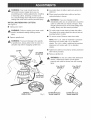
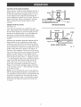
CRAFTSMAN
I _"°
_ '°"_'1
Double Insulated
Model No.
315.269210
18/32
Save this manual
future reference
CAU'nON:
7/16
13132
for
o Safety
o Features
Read and
follow aH Safety RuUes and
Operating Rnstructions before
first use of this product.
Customer
o Operation
o Maintenance
o Parts List
HeUp Line: 1-800-932-3188
Sears, Roebuck and Co., 3333 Bevedy Rd., Hoffman
Visit the Craftsman Web page: www.sears.com/craftsman
Estates,
RL 60179
USA
US
983000-028
1-03
FULL ONE YEAR WARRANTY
ON CRAFTSMAN
PROFESSIONAL
ROUTER
If this rRRFTSMRN router fails due to a defect in material or workmanship within one year from the date of
purchase, Sears wiii replace it, free of charge.
WARRANTY SERVICE IS AVAILABLE BY SIMPLY RETURNING THE TOOL TO THE NEAREST SEARS
STORE OR SEARS SERVICE CENTER IN THE UNITED STATES.
This warranty gives you specific legal rights, and you may also have other rights which vary from state to state.
Sears, Roebuck and Co., Dept. 817WA, Noffman
Estates, IL 60179
Your router has many features for making routing
operations more pleasant and enjoyable. Safety,
performance and dependability have been given top
priority in the design of this router making it easy to
maintain and operate.
,_
Look for this symboU to point
Your safety is involved.
,_
out important
safety
WARNING:
Do not attempt to use this tool until
you have read thoroughly and understand
completely the operator's manual. Pay close
attention to the safety rubs, including Dangers,
Warnings, and Cautions. If you use your tool
properly and only for what it is intended, you wiii
enjoy years of safe, reliable service.
precautions.
It means
attention!!!
WARNmNG: The operation of any router can result in foreign objects being thrown into your
eyes, which can result in severe eye damage. Before beginning power tool operation,
always wear safety goggles or safety glasses with side shields and a full face shield when
needed. We recommend Wide Vision Safety Mask for use over eyeglasses or standard
safety glasses with side shields, available at Sears Retail Stores. Always wear eye
protection which is marked to comply with ANSI Z87.1.
2
WARNING:Readandunderstand
aH
instructions.
FailuretofollowaHinstructions
HstedbeUow,
mayresuUt
in eUectric
shock,fire
and/orseriouspersonalinjury.
SAVE THESE
WORK
INSTRUCTmONS
AREA
[] Keep your work area ctean and well Jit. CUuttered
benches and dark areas invite accidents.
[] Do not operate power tooJs in expJosive atmospheres, such as in the presence of flammable
tiquids, gases, or dust. Power tooUs may create
sparks which may ignite the dust or fumes.
[] Keep bystanders, children, and visitors away
while operating a power tool. Distractions can
cause you to lose control.
ELECTRICAL
SAFETY
[] DoubJe insuJated tools are equipped with a
polarized pJug (one blade is wider than the
other). This plug will fit in a polarized outlet onty
one way. If the pJug does not fit fully in the
outlet, reverse the ptug. mfit still does not fit,
contact a qualified electrician to install a poJarized outtet. Do not change the plug in any way.
Double insulation [] eliminates the need for the
three-wire grounded power cord and grounded
power supply system.
[] Avoid body contact with grounded surfaces, such
as pipes, radiators, ranges, and refrigerators.
There is an increased risk of electric shock if your
body is grounded.
[] Don't expose power tools to rain or wet conditions. Water entering a power tool will increase the
risk of electric shock.
[] Do not abuse the cord. Never use the cord to carry
the tooJs or pull the pJugfrom an outlet. Keep cord
away from heat, oH, sharp edges, or moving parts.
Replace damaged cords immediately. Damaged
cords increase the risk of electric shock.
[] When operating a power tool outside, use an outdoor extension cord marked "W-A" or "W". These
cords are rated for outdoor use and reduce the risk of
electric shock.
PERSONAL
SAFETY
[] Stay alert, watch what you are doing and use
common sense when operating a power toot.
Do not use tooJ while tired or under the infJuence of drugs, alcohoJ, or medication. A moment
of inattention while operating power tools may
result in serious personal injury.
[] Dress property. Do not wear Joose clothing
jewelry. Contain tong hair. Keep your hair,
or
clothing, and gloves away from moving parts.
Loose clothes, jewelry, or long hair can be caught in
moving parts.
Avoid
before
on the
switch
accidentaJ starting. Be sure switch is off
plugging in. Carrying tools with your finger
switch or plugging in tools that have the
on, invites accidents.
Remove adjusting keys or wrenches before
turning the tooJ on. A wrench or a key that is left
attached to a rotating part of the tool may result in
[] Do not overreach. Keep proper footing and
baJance at aH times. Proper footing and balance
enables better control of the tool in unexpected
situations. Do not use on a ladder or unstable
support.
[] Use safety equipment. AJways wear eye protection. Dust mask, non-skid safety shoes, hard hat,
or hearing protection must be used for appropriate
conditions.
TOOL
USE AND CARE
[] Use cJamps or other practical way to secure
and support the workpiece to a stabJe platform.
Holding the work by hand or against your body is
unstable and may lead to loss of control.
[] Do not force toot. Use the correct toot for your
application. The correct tool will do the job better
and safer at the rate for which it is designed.
[] Do not use tool if switch does not turn it on or
off. Any tool that cannot be controlled with the
switch is dangerous and must be repaired.
[] Disconnect the ptug from power source before
making any adjustments,
changing accessories, or storing the tool Such preventive safety
measures reduce the risk of starting the tool
[] Store idle tools out of the reach of children
and
other untrained persons. Tools are dangerous in
the hands of untrained users.
[] Maintain tools with care. Keep cutting tools
sharp and cJean. Properly maintained tools with
sharp cutting edges are less likely to bind and are
easier to control.
[] Check for misalignment or binding of moving
parts, breakage of parts, and any other condition that may affect the tooJ's operation. If
damaged, have the tool serviced before using.
Many accidents are caused by poorly maintained
tools.
[] Use only accessories that are recommended by
the manufacturer for your model. Accessories
that may be suitable for one tool, may become
hazardous when used on another tool.
SERVICE
[] TooJservicemustbe performed
only by qualio
fied repair personnel. Service or maintenance
performed by unqualified personnel could result in
a risk of injury.
NoJd tooJ by insulated
contact hidden wiring
ADDITIONAL
RULES
[] When servicing a tooJ, use only identicaJ reo
pJacement parts. Follow instructions
in the
Maintenance section of this manual Use of
unauthorized parts or failure to follow Maintenance
hstructions may create a risk of eUectric shock or
injury.
gripping surfaces when performing an operation where the cutting tool may
or its cord. Contact with a "live" wire will make exposed metal parts of the tool "live" and
FOR SAFE
OPERATmON
[] Know your power tool Read operator's manuaJ
carefully. Learn its appJications and limitations,
as wen as the specific potentiaJ hazards related
to this tool Following this rule will reduce the risk
of electric shock, fire, or serious injury.
[] AJways wear safety glasses. Everyday eye°
glasses have onJy impact-resistant
tenses; they
are NOT safety gJasses. Following this rule wiii
reduce the risk of serious personal injury.
[] Make sure your extension cord is in good
condition. When using an extension cord, be
sure to use one heavy enough to carry the
current your product wilt draw. A wire gage size
(A.W.G.) of at Jeast 16 is recommended for an
extension cord 100 feet or tess in bngth. A cord
exceeding 100 feet is not recommended,
if in
doubt, use the next heavier gage. The smaller
the gage number, the heavier the cord. An
undersized cord will cause a drop in line voltage
resulting in loss of power and overheating.
[] Protect your lungs. Wear a face or dust mask if
the operation is dusty. Following this rule wiii
reduce the risk of serious personal injury.
[] inspect for and remove aH nails from tumber
before routing. Following this rule wiii reduce the
risk of serious personal injury.
[] Protect your hearing. Wear hearing protection
during extended periods of operation. Following
this rule will reduce the risk of serious personal
injury.
[] Drugs, aJcohoJ, medication. Do not operate tool
while under the influence of drugs, aJcohot, or
any medication. Following this rule wiii reduce the
risk of electric shock, fire, or serious personal injury.
[] inspect toot cords periodically and, if damaged,
have repaired at your nearest authorized sero
vice center. Constantly stay aware of cord
location. Following this rule will reduce the risk of
electric shock or fire.
[] Save these instructions.
Refer to them freo
quentJy and use them to instruct others who
may use this tool ff you Joan someone this toot,
toan them these instructions also.
[] Check damaged parts. Before further use of the
tool, a guard or other part that is damaged
should be carefully checked to determine that it
wilt operate properly and perform its intended
function. Check for aJignment of moving parts,
binding of moving parts, breakage of parts,
mounting, and any other conditions that may
affect its operation. A guard or other part that is
damaged shouJd be property repaired or reo
placed by an authorized service center. Following this rule will reduce the risk of shock, fire, or
serious injury.
,&
[] Do not abuse cord. Never carry the tool by the
cord or yank it to disconnect it from the recepo
tac[e. Keep cord away from heat, oiJ, and sharp
edges. Following this rule wiii reduce the risk of
electric shock or fire.
WARNING:
Some dust created by power
sanding, sawing, grinding, drilling, and other
construction activities contains chemicals known
to cause cancer, birth defects or other
reproductive harm. Some examples of these
chemicals are:
o lead from bad-based
paints,
o crystalline silica from bricks and cement and
other masonry products, and
o arsenic and chromium
treated lumber.
from chemically-
Your risk from these exposures varies,
depending on how often you do this type of work.
To reduce your exposure to these chemicals:
work in a well ventilated area, and work with
approved safety equipment, such as those dust
masks that are specially designed to filter out
microscopic particles.
important: Some of the following symbols may be used on your tool. Please study them and barn their meaning.
Proper interpretation of these symbols wiii allow you to operate the tool better and safer.
SYMBOL
NAME
DESmGNATmON/EXPLANATmON
V
Volts
Voltage
A
Amperes
Current
Hz
Hertz
Frequency (cycles per second)
W
Watt
Power
Minutes
Time
Alternating Current
Type or a characteristic of current
No Load Speed
Rotational speed, at no load
Class H Construction
Designates double-insulated
construction tools
min
no
._/min
Revolutions or Reciprocation
Per Minute
Revolutions, strokes, surface speed,
orbits etc. per minute
Safety Alert
Undicates danger, warning or caution.
Utmeans attention!!! Your safety is
involved.
Wet Conditions Alert
Do not expose to rain or use in damp
locations.
The purpose of safety symbols is to attract your attention to possible dangers. The safety symbols, and the
explanations with them, deserve your careful attention and understanding. The safety warnings do not by
themselves eliminate any danger. The instructions or warnings they give are not substitutes for proper accident
prevention measures.
SYMBOL
MEANmNG
DANGER:
Failure
to obey a safety
warning
will result
serious shock
injury to
yourself
or toinjury.
others. Always
follow
the safety
precautions
to reduce
the risk
of fire,inelectric
and
personal
WARNmNG:
to obey
a safetytowarning
result
in serious
yourself
or to injury.
others.
Always follow Failure
the safety
precautions
reduce can
the risk
of fire,
electricinjury
shockto and
personal
CAU'NON:
Failure Always
to obey follow
a safety
may result toinreduce
property
or electric
personalshock
injuryand
to
yourself
or to others.
the warning
safety precautions
thedamage
risk of fire,
personal injury.
NOTE:
Advises you of information or instructions vital to the operation or maintenance of the equipment.
SAVE THESE iNSTRUCTiONS
Depth of Cut
CoHet
Horsepower
input
0 - 1-1/2 in.
1/2 in. and 1/4 in.
2
No Load Speed
Power Cord
Net Weight
15,000 - 25,000/min
10 ft.
7 Ibs=6 oz=
120 volts, 60 Hz, AC only, 9.5 amps
Your router has been shipped completely assembled.
Unspect it carefully to make sure no breakage or
damage has occurred during shipping. Rfany parts are
damaged or missing, contact your nearest Sears
Retail Store to obtain replacement parts before
attempting to operate router. A wrench, a 1/4 in. collet
assembly, and this operator's manual are also
included=
,_
WARNING:
Rfany parts are missing, do not
operate this tool until the missing parts are
replaced. Failure to do so could result in possible
serious personal injury.
DOUBLE iNSULATION
DEPTH
DouMe insulation is a concept in safety in eUectric
power tooUs, which eliminates the need for the usuaU
three-wire grounded power cord. AH exposed metaU
parts are isoUated from the internaU metaU motor
components with protecting insuUafion. DouMe
insuUated tooUsdo not need to be grounded.
The depth adjusting ring allows you to adjust the
depth of cut.
Important: Servicing of a tooUwith douMe insuUafion
requires extreme care and knowUedge of the system
and shouUd be performed onUyby a qualified service
technician. For service, we suggest you return the tooU
to your nearest authorized service center for repair.
AUways use original factory replacement parts when
servicing.
CHIP SHIELD
_
WARNmNG: The double insulated system is
intended to protect the user from shock resulting
from a break in the tool's internal wiring. Observe
all normal safety precautions to avoid electrical
shock.
ELECTRICAL
CONNECTmON
Your router has a precision built electric motor, mt
should be connected to a power suppJy that is 120
voJts, 60 Hz, AC onJy (normal househoJd current).
Do not operate this toot on direct current (DO}. A
substantial voltage drop will cause a loss of power
and the motor will overheat. If your tool does not
operate when plugged into an outlet, double-check
the power supply.
SWmTCH
To turn the router ON, toggle the switch to the l
position. To turn the router OFF, toggle the switch to
the O position.
SPINDLE
LOCK
The spindle lock secures the spindle while you make
adjustments and acts as a retainer to keep the router
body from coming out of the base.
ADJUSTmNG
LOCKING
RING
ARM
The locking arm secures the motor housing in the
base.
A clear plastic chip shield is installed on the front of
your router for protection against flying dust and
chips. The shield is designed to fit the opening of the
router base. If necessary to remove chip shield,
squeeze the tabs on each end and pull outward. To
replace, squeeze the tabs at each end, fit into
opening, then release. For your protection, do not
use router without chip shietd properly in pJace.
Peel the horsepower label from chip shield and
discard.
VARIABLE
SPEED
Your router has advanced electronic features,
designed to assist you in getting the maximum use
from your router. By making proper speed selections,
your router can be adjusted to specific routing needs.
This eliminates much of the guess work previously
needed to perform a given job. Both the experienced
and inexperienced router users benefit, obtaining
professional like results with fewer job errors.
The variable speed control allows the router speed to
be adjusted from 15,000 to 25,000 RPM. The
variable speed control selector is conveniently located
on the top of the motor housing.
Speed can be set according to the approximate cutter
diameter you will be using and to the hardness of the
material being cut. The best cuts are made when the
cutter is fed through material at the proper rate of
feed.
VACUUM
ATTACHMENT
The vacuum attachment allows you to attach a
standard shop vacuum to the router for easy clean up.
HANDLE
POWER
HANDLE
WRENCH
1/4in.
COLLET
ASSEMBLY
DEPTH
ADJUSTING
LOCKING
ARM
SPINDLE
LOCK
COLLET
NUT
,_
Fig:1
WARNmNG: Do not allow familiarity with your router to make you careUess, Remember that a careUess fraction
of a second is sufficient to inflict severe injury,
8
_
WARNING:YourroutershouUd
neverbe
connectedtopowersuppUy
whenyouare
assembfing
parts,makingadjustments,
installing
or removingcutters,cbaning,or whennotin
use.Disconnecting
routerwHU
preventaccidentaU
startingthatcouUd
causeseriouspersonaU
injury.
INSTALUNG/RE_OVmNG
CUTTERS
[] Lay router down on table to gain easy access to
collet nut.
[] Place wrench provided onto collet nut and turn
couterclockwise to loosen.
_l
WARNING:
Rfyou are changing a cutter
immediately after use, be careful not to touch the
cutter or collet with your hands or fingers. They
will get burned because of the heat buildup from
cutting. Always use the wrench provided.
See Figure 2.
[] Unplug your router.
,_
WARNING:
Failure to unplug your router could
result in accidental starting causing serious
[] Depress spindle lock.
,_
[]
To install cutter: Insert shank of cutter into collet.
The shank of the cutter should be close to but not
touching bottom of collet.
[]
To remove cutter: Remove cutter from collet.
NOTE: The 1/2 in. collet is machined to precision
tolerances to fit cutters with 1/2 in. diameter
shanks. The 1/4 in. collet is machined to precision
tolerances to fit cutters with 1/4 in. diameter
shanks.
WARNING:
To prevent damage to the spindle
or spindle lock, always allow motor to come to a
complete stop before engaging spindle lock.
CUTTER
COLLET
NUT
TO LOOSEN
COLLETNUT
[] Tighten the collet nut securely by turning clockwise
with wrench provided.
[] Release spindle lock.
WRENCH
,_.
WARNING:
Do not use cutters with undersized
shanks. Undersized shanks wiii not tighten
properly and could be thrown from tool causing
injury.
1/4in. COLLET
ASSEMBLY
1/2 in. COLLET
ASSEMBLY
TOTIGHTEN
COLLETNUT
DEPRESS
SPINDLELOCK
Fig. 2
CUTTERWiTH1/4 in.
SHANK DIAMETER
CUTTERWiTH1/2 in.
SHANK DIAMETER
ADJUSTmNG
DEPTHOF CUT
[] Turn the depth indicator ring until the zero fines up
with the indicator point on the base. See F_gure 5.
See Figures 3, 4, 5, and 6.
We recommend that cuts be made at a depth not
exceeding 1/8 in. and that several passes be made to
reach depths of cut greater than 1/8 in.
[] Unplug your router.
_
WARNING:
Failure to unplug your router could
result in accidental starting causing serious
[] Place router on a fiat surface and loosen locking
arm. See Figure 3.
CUTTERAT ZERO
DEPTHOFCUT
LOCKING
ARM
LOOSEN
Fig. 5
[] Position router so that the cutter can extend below
the subbase for desired depth setting. See
Figure 6.
Fig. 3
[] Turn depth adjusting ring until cutter is inside
subbase. See Figure 4.
[] Turn depth adjusting ring until tip of cutter touches
fiat surface.
TO RAISE
CUTTER
TO
LOWER
CUTTER
\
CUTTEREXTENDED
BELOWSUBBASE
DEPTH
ADJUSTING
RiNG
iNDICATOR
POINT
CUTTER
iNSiDESUBBASE
[] Turn the depth adjusting ring to obtain the desired
depth of cut. The distance the cutter moves can be
read on the depth adjusting ring. Each mark on the
depth adjusting ring indicates 1/32 inch change in
depth setting, indicator point is located on the
base.
DEPTH
iNDiCATOR
RiNG
SUBBASE
Fig. 6
[] Tighten locking arm securely.
Fig. 4
10
ADJUSTING
DEPTH
The speed selecfion chart shown gives suggested
speed settings based on the diameter of the cutter
and the type of materiai being routed,
OF CUT (WroTH ROUTER
See Figure 7.
We suggest that you practice with the variabie speed
feature of your router before instaiHng a cutter and
making cuts in wood,
The indicator point on the base can be used when
using your router mounted to a router tame,
[] Set the cutter at zero depth of cut,
[] Rotate depth indicator ring to desired depth of cut
on the scab, Refer to "ADJUSTING DEPTH OF
CUT" earlier in this manual
SPEED SELECTION CHART
CUTTER SIZE
[] Tighten Hocking arm secureiy,
MATERIAL
1/4
3/8
1/2
3/4
FOR ROUTER TABLE USE ONLY
INDICATOR
POINT
DEPTH
ADJUSTMENTRING
Fig, 7
ADJUSTING
SPEED
See Figure 8.
Your router has a variabHe speed eontroH seHector
designed to aHHowoperator controH of speed and
torque iimits. You can make speed selections best
suited to the type of cut, the materiai being cut, and
the size of bit being used. The variabie speed controi
selector allows you to adjust router speed from 15,000
to 25,000 RPM. There is a six-step scab (A to F) on
the variabHe speed controH seHector. To increase the
speed and torque of your router, turn the variable
speed control selector to a higher setting (F). Turn to
a lower setting to decrease speed and torque.
Fig. 8
iNSTALLiNG
THE VACUUM
ATTACHMENT
[] Place the vacuum attachment in the area at the
rear of the router under the Hocking arm.
[] Secure the vacuum attachment with the two
screws provided.
NOTE: If you do not want to use the variable speed
control selector, turn it to the highest possible setting,
and the feature will not be active.
11
HELPFUL
7"
HINTS
AUways damp workpbce
STARTING/STOPPING
[] Grasp handles using both hands, See Figure 9.
secureUy before routing,
V" A safe operator is one who thinks ahead,
V" AUways wear eye protection when routing,
7"
Make setup adjustments carefully, Then doubb
check, Measure twice and cut once,
7"
Keep cutters dean and properUy sharpened,
7"
Don't bt familiarity make you carebss,
7"
Study aH safety rubs and do the job safeUy,
[]
To start muter: Press the switch to the 1position, See
Figure 10.
[]
To stop muter: Press the switch to the O position,
See Figure 10.
HANDLE
V" Never pUaceyour hands in jeopardy,
V" Make certain damps can't bosen while in use,
7"
Test difficuUt setups on scrap -- Don't waste
Uumber.
7"
PUaneach operation before you begin,
7"
Provide for smoother operation by cleaning your
ROUTER
POWER
HANDLE
router frequendy, Shake router or Mow with an air
jet to remove sawdust buildup,
7" Think safety by thinking
ahead.
Fig. 9
(0 )TO STOP
(I) TO START
SWITCH
Fig. 10
12
PLACINGROUTERON WORKPIECE
FEEDING
PUacing your router on a workpbce differs, depending
on the type of routing: edge routing or internaU routing.
The "secret" of professional routing and edge shaping
lies in making a careful set-up for the cut and in
selecting the proper rate of feed.
_
RATE OF FEED
WARNING:
Remain alert and watch what you
are doing. Do not operate router when fatigued.
The proper rate of feed depends on several factors:
the hardness and moisture content of the wood, the
depth of cut, and the cutting diameter of the bit. When
cutting shallow grooves in soft woods such as pine, a
faster rate of feed can be used. When making deep
cuts in hardwoods such as oak, a slower rate of feed
should be used.
EDGE ROUTING
[] Place router on edge of workpiece, making sure
the router bit does not contact workpiece.
[] Turn router on and let motor build to its full speed.
[] Begin your cut, gradually feeding cutter into
workpiece.
_
The best rate of feed is one that does not slow down
the router motor more than one-third of its no-load
WARNING:
Keep a firm grip on router with both
hands at aii times. Failure to do so could result in
speed. If the router is fed too fast, it will take large
chips out of the wood and leave gouge marks, ff the
router is fed too slow, it wiii scorch or burn the wood.
loss of control leading to possible serious injury.
[] Upon completion of cut, turn motor off and let it
come to a complete stop before removing router
from work surface.
,_
Feeding Too Fast
Clean, smooth routing and edge shaping can be done
only when the bit is revolving at a relatively high
speed and is taking very small bites to produce tiny,
cleanly severed chips. If your router is forced to move
forward too fast, the RPM of the bit becomes slower
than normal in relation to its forward movement. As a
WARNING:
Never pull router out of work and
place upside down on work surface before the
cutter stops.
INTERNAL
result, the bit must take bigger bites as it revolves.
"Bigger bites" mean bigger chips, and a rougher
finish. Bigger chips also require more power, which
could result in the router motor becoming overloaded.
ROUTING
[] Tilt router and place on workpiece, letting edge of
subbase contact workpiece first.
Under extreme force-feeding conditions the relative
RPM of the bit can become so slow--and the bites it
NOTE: Be careful not to let router bit contact
workpiece.
has to take so large -- that chips will be partially
knocked off (rather than fully cut off), resulting in
splintering and gouging of the workpiece. See
Figure 11.
[] Turn router on and let motor build to its full speed.
[] Feed cutter into workpiece gradually until subbase
is level with workpiece.
,_
Your router is an extremely high-speed tool (15,000 25,000 RPM no-load speed), and will make clean,
smooth cuts if allowed to run freely without the
overload of a forced (too fast) feed. Three things that
cause "force feeding" are bit size, depth-of-cut, and
workpiece characteristics. The larger the bit or the
deeper the cut, the more slowly the router should be
advanced. Rfthe wood is very hard, knotty, gummy or
damp, the operation must be slowed still more.
WARNING:
Keep a firm grip on router with both
hands at all times. Failure to do so could result in
loss of control leading to possible serious injury.
[] Upon completion of cut, turn motor off and let it
come to a complete stop before removing router
from work surface.
_
ROUTER
WARNING:
Never pull router out of work and
place upside down on work surface before the
cutter stops.
You can always detect "force feeding" by the sound of
the motor. Its high-pitched whine will sound lower and
stronger as it loses speed. Also, the strain of holding
the tool will be noticeably increased.
13
DIRECTION (EXTERNAL)
See Figure 12.
Feeding Too Slow
Utis aBo possiMe to spoil a cut by moving the router
forward too sbwUy. When it is advanced into the work
too sbwUy, a revoMng bit does not dig into new wood
fast enough to take a bite; instead, it simpUy scrapes
away sawdust-Hke partbbs. Scraping produces heat,
which can gUaze, burn, or mar the cut and in extreme
cases, can even overheat the bit so as to destroy its
hardness.
The router motor and bit revolve in a clockwise
direction. This gives the tool a slight tendency to twist
(in your hands) in a counterclockwise direction,
especially when the motor revs up (as at starting).
Because of the extremely high speed of bit rotation
during a "proper feeding" operation, there is very little
kickback to contend with under normal conditions.
However, should the bit strike a knot, hard grain,
foreign object, etc. that would affect the normal
progress of the cutting action, there will be a slight
kickback--sufficient
to spoil the trueness of your cut if
you are not prepared. Such a kickback is always in
the direction opposite to the direction of bit rotation.
Unaddition, it is more difficuUt to controU a router when
the bit is scraping instead of cutting. With practically
no bad on the motor the bit wHUbe revoMng at dose
to top RPM, and wHUhave a much greater than normaU
tendency to bounce off the sides of the cut (especially
if the wood has a pronounced grain with hard and soft
areas). As a result, the cut produced may have
rippled, instead of straight sides. See Figure 11.
To guard against such a kickback, plan your setup
and direction of feed so that you will always be
thrusting the tool--to hold it against whatever you are
using to guide the cut--in the same direction that the
leading edge of the bit is moving. In short, the thrust
should be in a direction that keeps the sharp edges of
the bit continuously biting straight into new (uncut)
wood.
"Too-slow feeding" can also cause your router to take
off in a wrong direction from the intended line of cut.
Always grasp and hoJd your router firmly with
both hands when routing.
You can detect "too-slow feeding" by the runaway,
high-pitched sound of the motor; or by feeling the
"wiggle" of the bit in the cut.
sT
PROPER CUTTING SEQUENCE
4
TOOFAST
Fig. 12
TOOSLOW
Fig. 11
14
DIRECTION
(INTERNAL)
Wheneveryouareroutinga groove,yourtravel
shouldbeina directionthatplaceswhateverguide
youareusingat theright-hand
side.Inshort,when
theguideis positioned
as shownin thefirstpartof
Figure13,tooltravelshouldbeleftto rightand
counterclockwise
aroundcurves.Whentheguideis
positionedasshowninthesecondpartof Figure13,
tooltravelshouldberighttoleftandclockwisearound
curves.Rtfhereis a choice,thefirstsetupis generally
theeasiesttouse.Ineithercase,thesidewaysthrust
youuseis againsttheguide.
GUIDE
OUTSIDE
ROTATION
THRUST
DEPTH
OF CUT
As previously mentioned, the depth of cut is important
because it affects the rate of feed that, in turn, affects
the quality of the cut (and, also, the possibility of
damage to your router motor and bit). A deep cut
requires a slower feed than a shallow one, and a too
deep cut will cause you to slow the feed so much that
the bit is no longer cutting, it is scraping, instead.
Making a deep cut is never advisable. The smaller
bits -- especially those only 1/16 inch (1.6 mm) in
diameter -- are easily broken off when subjected to
too much side thrust. A large enough bit may not be
broken, but if the cut is too deep a rough cut will result
-- and it may be very difficult to guide and control the
bit as desired. For these reasons, we recommend that
you do not exceed 1/8 in. depth of cut in a single
pass, regardless of the bit size or the softness or
condition of the workpiece. See FiXTure 14.
To make deeper cuts it is therefore necessary to
make as many successive passes as required,
lowering the bit 1/8 in. for each new pass. In order to
save time, do all the cutting necessary at one depth
setting, before lowering the bit for the next pass. This
will also assure a uniform depth when the final pass is
completed. See FiXTure 15.
ROTATION
FEED
DETERMINING
GUIDE
DEPTH
OFCUT
GUIDE
INSIDE
__
WIDTH
ROTATION
C_
GUIDE
@
÷
THRUST
Fig. 14
ROTAT OH
FEED
/
1ST.
Fig. 13
2HD.
[7
PASS
PASS
_U
m
2ND.PASS
Fig. 15
15
ROUTING
Yourrouterisa versatiletooUandcarlbeusedfor
marlydifferentappHcations.
Youmayroutgrooves,
carvedesignsusinga tempUate,
carvedesignsby
freehand,tapertaNeandchairUegs,
mortisedoor
jambs,orcreatejoints.
ROUTING
GROOVES
See Figure 16.
When routing across the face of boards, set router at
desired depth of cut, pUacethe edge of router base
against workpiece, and turn on the router. SbwUy feed
the cutter into the workpiece along desired Hne of cuL
,_
WARNING:
If desired depth of cut is greater
than can be safeUy cut in one pass, make cuts in
two or more passes,
Fig, 16
When routing straight cuts across stock, damp a
straight edge to the workpiece to use as a guide,
Position the straightedge parallel to the line of cut and
offset the distance between the cutting edge of the
cutter and the edge of the router base, Hold the router
base against the straightedge and rout the groove,
Rout the pattern in two or more passes, Make the
first pass at 25% of the desired depth of cut, This
will provide better control as well as being a guide
for the next pass,
NOTE: Do not rout deeper than 1/8 in, per pass,
When routing a groove wider than the diameter of the
cutter, clamp a straightedge on both sides of the
cutlines, Position both guides parallel to the desired
line of cut and spaced equal distances from the
desired edges of the groove, Rout along one guide;
then, reverse direction and rout along the other guide,
Clean out any remaining waste in the center of the
,_
WARNING:
Do not use large router bits for
freehand routing. Use of large router bits when
freehand routing could cause loss of control or
create other hazardous conditions that could
cause possible serious personal injury. When
using a router table, large router bits should be
used for edging only. Do not use router bits that
are larger in diameter than the opening in router
base for any purpose.
ROUTING BY FREEHAND
See F_Ture 17.
When used freehand, your router becomes a flexible
and versatile tool. This flexibility makes it possible to
easily rout signs, relief sculptures, etc.
There are two basic techniques for freehand routing:
[] Routing letters, grooves, and patterns into woo&
[] Routing out the background, leaving the letters or
pattern raised above the surface.
When freehand routing, we suggest the following:
[] Draw or layout the pattern on workpiece.
[] Choose the appropriate cutter.
NOTE: A core box or V-groove bit is often used for
routing letters and engraving objects. Straight bits
and ball mills are often used to make relief
carvings. Veining bits are used to carve small,
intricate detail&
Fig, 17
16
ROUTING
WITHGUIDEBUSHINGS
WhenusingtheTempUate
GuideBushingsItemNo.925082withyourrouter,youmustvisuallycenterthe
bitwiththebushingbeforebeginning
yourcut.Your
routersubbasemaybeadjustedby boseningthe
screwshoUding
thesubbasetoyourrouter.Besureto
tightenbcHngarmbeforecenteringbit in bushing.
Aftercenteringbitwithbushing,tightenscrews
secureUy.
EDGINGWITHPILOTBITS
TOPEDGESHAPING
See Figure 18.
Arbor-type bits with pilots are excellent for quick,
easy, edge shapinga They wHUfollow workpbce edges
that are either straight or curved. The pilot prevents
the bit from making too deep a cut; and hoUding the
pilot firmUy in contact with the workpbce edge
throughout prevents the cut from becoming too
shallow.
Go,oE
Whenever the workpiece thickness together with the
desired depth of cut (as adjusted by router depth
setting) are such that only the top part of the edge is
to be shaped (leaving at bast a 1/16 inch thick uncut
portion at bottom), the pilot can ride against the uncut
portion, which wiii serve to guide it. See Figure /8.
However, if the workpiece is too thin or the bit set too
low so that there will be no uncut edge to ride the pilot
against, an extra board to act as a guide must be
placed under the workpiece. This "guide" board must
have exactly the same contour -- straight or curved
-- as the workpiece edge. If it is positioned so that its
edge is flush with the workpiece edge, the bit will
make a fuji cut (in as far as the bit radius). On the
other hand, if the guide is positioned as shown in
Figure 18 (out from the workpiece edge), the bit will
make less than a full cut -- which will alter the shape
of the finished edge.
WHOLE EDGE SHAPING
Fig. 18
NOTE: Any of the piloted bits can be used without a
pilot for edge shaping with guides, as preceding. The
size (diameter) of the pilot that is used determines the
maximum cut width that can be made with the pilot
against the workpiece edge - the small pilot exposes
all of the bitl the large one reduces this amount by
1/16 inch.
17
_
WARNING:Whenservicing,useonUy
idenficaU
CraftsmanrepUacement
parts.Useofanyother
partmaycreatea hazardor causeproduct
damage.
GENERAL
Orfiythe partsshownonthepartsHst,areintendedto
berepairedor repUaced
by thecustomer.AHother
partsrepresentan importantpartofthedouMe
insuUafion
systemandshouUd
beservicedonUy
bya
qualifiedSearsservicetechnician.
AvoidusingsoUvents
whencleaningpUasfic
parts.
MostpUastics
aresuscepfiMe
todamagefromvarious
typesofcommerdaU
soUvents
andmaybedamaged
bytheiruse.UsedeancUoths
toremovedirt,carbon
dust,etc.
COLLET
Dustandchipsmaycollectonthecolletfromtimeto
time,makingit necessarytocleanthecollet.Todo
so,removethecolletassemblyandwipeit witha
cleandryrag.Cleanthetaperintheshaftin thesame
manner.Neverimmersethecolletor endoftheshaft
in a solventor inwater.Beforereplacingthecollet
assembly,
puta dropof SAE30motoroilonthe inside
ofthenut,onthethreadsoftheshaft,andon the
taperintheshaft.Replacethecolletassemblyonto
theshaftbyhandonly.Nevertightenthecolletnut
withouta bit inthecollet.Thisactioncould
permanently
damagethecollet.
LUBRICATION
_1_ WARNING:Donotat anytimeUetbrakefluids,
gasoline,petroleum-based
products,penetrating
oils,etc.comeincontactwithplasticparts.They
containchemicals
thatcandamage,weakenor
destroyplastic.
It hasbeenfoundthatelectrictoolsaresubjectto
accelerated
wearandpossibleprematurefailurewhen
theyareusedonfiberglassboats,sportscars,
wallboard,spacklingcompounds,
or plaster.The
chipsandgrindingsfromthesematerialsarehighly
abrasivetoelectrictoolpartssuchasbearings,
brushes,commutators,
etc.Consequently,
it is not
recommended
thatthistoolbeusedforextended
workonanyfiberglassmaterial,wallboard,spackling
compounds,
or plaster.Duringanyuseonthese
materialsit is extremely
importantthatthetoolis
cleanedfrequentlyby blowingwithanairjet.
CUTTERS
Getfastermoreaccuratecuttingresultsbykeeping
cutterscleanandsharp.Removeallaccumulated
pitchandgumfromcuttersaftereachuse.
Whensharpening
cutters,sharpenonlytheinsideof
thecuttingedge.Nevergrindtheoutsidediameter.Be
surewhensharpening
theendof a cutterto grindthe
clearance
anglethesameas originallyground.
All of the bearings in this tool are lubricated with a
sufficient amount of high grade lubricant for the life of
the unit under normal operating conditions. Therefore,
no further hJbrication is require&
EXTENSION
The use of any extension cord will cause some loss of
power. To keep the loss to a minimum and to prevent
tool overheating, use an extension cord that is heavy
enough to carry the current the tool will draw.
A wire gage size (A.W.G.) of at least 14 is
recommended for an extension cord 100 feet or less
in length. When working outdoors, use an extension
cord that is suitable for outdoor use. The cord's jacket
will be marked WA
,_
CAUTION:
Keep extension cords away from the
cutting area and position the cord so that it will
not get caught on lumber, tools, etc. during
_
WARNING:
Check extension cords before each
use. If damaged replace immediately. Never use
tool with a damaged cord since touching the
damaged area could cause electrical shock
resulting in serious injury.
Extension cords suitable for use with your router are
available at your nearest Sears Retail Store.
,_
18
CORDS
WARNING:
Always wear safety goggles or
safety glasses with side shields during power
tool operation or when blowing dust. If operation
is dusty, also wear a dust mask.
THEFOLLOWING
RECOMMENDED
ACCESSORIES
ARE
CURRENTLY
AVAILABLEATSEARSRETAILSTORES
TempJate
GuideBushings
DovetailTemplate
BoxJoint Template
_
ROUTER
WARNING:
Butt HingeTemplate
MuitiopurposeRouterGuide
Rout- A - Form Pantograph
The use of attachments oFaccessories
TABLES
With a router table your router is converted
high-speedshaper.
GUIDE
not listed above might be hazardous,
BUSHINGS
Guide bushings allow for accurate guiding of router
along any workpiece oF template edge and for
grooving oF shaping of curved contours,
into a
WARNING:
Only use router tables with proper
guarding for the cutter and with "on board" switch
controlled receptacles (Part No, 9-25188)=
Failure to use router tables with appropriate
safety features could result in serious personal
19
CRAFTSMAN
ROUTER-
MODEL
NUMBER
315.'269210
-._
2
SEENOTE
3
4
22
12
5
7
11
8
11
2O
18
_14
m
19
i 7
_25
24
NOTE: The assemMy shown represents an important part of the douMe insuUated system, To avoid the possibility
of aUterafion or damage to the system, service shouUd be performed by your nearest Sears repair center,
Contact your nearest Sears retail store for service center information,
2O
CRAFTSMAN
ROUTER
- MODEL
NUMBER
315.269210
J
The
number wiii regarding
be found on
a plate
attached
to the ordering
motor housing.
Always mention the model number |
in
aiimodel
correspondence
your
ROUTER
or when
repair parts.
SEE BACK PAGE FOR PARTS
ORDEFtING
iNSTRUCTiONS
PARTS UST
Key
No.
Part
No.
1
983014-001
2
982899-014
3
982716-001
4
982959-001
5
703477-057
6
706382-357
7
982972-001
8
982971-002
9
982948-032
10
982990-001
11
982500-131
12
617966-030
13
983060-007
14
982379-001
15
623173-006
16
998586-001
17
612191-004
18
982993-001
19
982966-001
20
982991-001
21
982890-002
22
982890-001
23
982889-001
24
982970-001
25
643115-005
983000-028
* Standard Hardware Item -- May Be Purchased Locally
** Available from Div. 98 -- Source 980.00
21
Your Home
For repair-in
your home-of
all major brand appliances,
lawn and garden equipment, or heating and cooling systems,
no matter who made it, no matter who sold it!
..................
For the replacement parts, accessories and
owner's manuals that you need to do-it-yourself.
..................
For Sears professional installation of home appliances
and items like garage door openers and water heaters.
..................
1-8 00-4-MY-H 0 ME® (1-800-469-4663)
oa,,
an t, o, o,oht sod
Oaoada
www.sears.com
..........
www.sears.ca
Our
Home
For repair of carry-in items like vacuums, lawn equipment,
and electronics, call or go on-line for the location of your nearest
Sears Parts & Repair Center.
1-800-488-1222
Call anytime,
day or night (U.S.A. only)
www.sears.com
To purchase a protection agreement (U.S.A.)
or maintenance agreement (Canada) on a product serviced
1-800-827-6655
Pard pedir servicio
(U.S.A.)
1-800-361-6665
de reparacien
Au Canada
a domicilio, y para ordenar piezas.
1-8 8 8-S U- HO G AR sM
by Sears:
(Canada)
pour service en frangais:
1 -800- LE- FO YER Mc
(1-800-533-6937)
(1-888-784-6427)
www.sears.ca
...............
..............
SEARS
® Registered
Trademark
/ TMTrademark
/
SM
Service
Mark of Sears,
Roebuck
® Marca Registrada
/ TM Marca de F_brica / SM Marca de Servicio
de Sears,
MC
Marque
de commerce
/ MD Marque
d6pos6e
de Sears,
Roebuck
and Co.
and Co.
Roebuck
and
Co.
® Sears,
Roebuck
and Co.