1
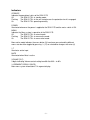
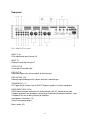
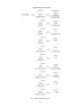
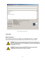
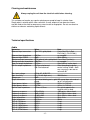
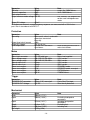
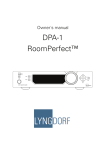
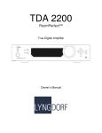
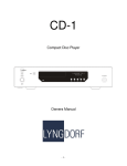
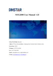
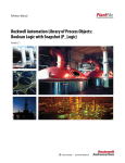
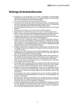
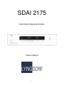
SDAI 2175
Semi Digital Integrated Amplifier
Owners Manual
-1-
Table of Contents
WARNINGS.........................................................................................................................................3
Explanation of graphical symbols .....................................................................................................3
Exclamation symbol.....................................................................................................................3
Lightning symbol.........................................................................................................................3
Important safety instructions.............................................................................................................4
Unpacking the SDAI 2175 ....................................................................................................................4
Accessories ......................................................................................................................................5
Operating voltage .............................................................................................................................5
Product Registration..............................................................................................................................5
Introduction ..........................................................................................................................................6
Front panel............................................................................................................................................7
Controls............................................................................................................................................7
Indicators .........................................................................................................................................8
Rear panel.............................................................................................................................................9
Menu system.......................................................................................................................................10
Software .............................................................................................................................................12
Connectors..........................................................................................................................................13
Mains Connector ............................................................................................................................13
Loudspeaker connectors .................................................................................................................14
Input connectors .............................................................................................................................14
Balanced inputs..........................................................................................................................14
Unbalanced inputs......................................................................................................................14
Trigger connectors..........................................................................................................................14
Cleaning and maintenance...................................................................................................................15
Technical specifications ......................................................................................................................15
Audio .............................................................................................................................................15
Protection .......................................................................................................................................16
Mains .............................................................................................................................................16
Trigger ...........................................................................................................................................16
Mechanical.....................................................................................................................................16
Technical assistance............................................................................................................................17
Support ...............................................................................................................................................17
-2-
WARNINGS
CAUTION
RISK OF ELECTRICAL
SHOCK. DO NOT OPEN
CAUTION: TO REDUCE THE RISK OF ELECTRICAL SHOCK,
DO NOT REMOVE COVER. NO USER-SERVICEABLE PARTS
INSIDE. REFER SERVICING TO QUALIFIED PERSONNEL.
TO REDUCE RISK OF FIRE OR ELECTRIC SHOCK, DO NOT EXPOSE THIS APPLIANCE TO RAIN OR MOISTURE.
Explanation of graphical symbols
Exclamation symbol
The exclamation point within an equilateral triangle is intended to alert the user
to the presence of important operating and maintenance (servicing) instructions
in the literature accompanying the product.
Lightning symbol
The lightning with arrowhead symbol within an equilateral triangle is intended to
alert the user to the presence of uninsulated “Dangerous Voltage” within the
products’ enclosure that may be of sufficient magnitude to constitute a risk of
electrical shock to a person.
-3-
Important safety instructions
1:Read these instructions carefully before installing or operating this apparatus.
2:Keep these instructions.
3:Heed all warnings.
4:Follow all instructions.
5:Do not use this apparatus near water.
6:Clean only with a dry cloth.
7:Do not block any ventilation openings. Install in accordance with the manufacturer’s
instructions.
8:Do not install near any heat sources such as radiators, heat registers, stoves, or other
apparatus that produce heat.
9:Do not defeat the safety purpose of the grounding-type plug. A grounding-type plug has
two pins and a third grounding prong. The third prong is provided for your safety. If the
provided plug does not fit into your outlet, consult an electrician for replacement of the
obsolete outlet.
10:Protect the power cord from being walked on or pinched, particularly at plugs,
convenience receptacles, and the point where they exit from the apparatus. Do not use
this unit with a damaged cord or plug.
11:Only use attachments and accessories specified by the manufacturer.
12:Use only with cart, stand, bracket, or table specified by the manufacturer, or sold with the
apparatus. When a cart is used, use caution when moving the cart/apparatus
combination to avoid injury from tipping-over.
13:Unplug this apparatus during lightning storms or when unused for long periods of time.
14:Connect only to the proper mains voltage.
15:Do not connect any output from the amplifier to any other amplifier's output or any other
voltage source.
15:To avoid electrical shock, make sure that no conductive part of the loudspeaker wiring is
exposed while the amplifier is operating. Do not connect loudspeakers with uninsulated
terminals to the amplifier.
17:Refer all servicing to qualified service personnel. Servicing is required when the
apparatus has been damaged in any way, such as when the power-supply cord or plug
are damaged, liquid has been spilled or objects have fallen into the apparatus, the
apparatus has been exposed to rain or moisture, does not operate normally or has been
dropped.
Unpacking the SDAI 2175
Carefully remove the unit and accessory kit from the carton, visually check for shipping
damage. Contact both the shipper and Lyngdorf Audio immediately if the unit bears any
sign of damage from mishandling. All Lyngdorf Audio equipment is carefully inspected
before leaving our factory.
KEEP SHIPPING CARTON AND PACKING MATERIALS for future use or in the
unlikely event that the unit needs servicing. If this unit is shipped without the
original packing, damage could occur and void the warranty.
-4-
Accessories
You should find the following in the accessory kit:
1:One mains cord.
2:This manual.
3:Customer registration form.
Operating voltage
The SDAI 2175 is available in a version for 115V mains voltage and in a version for 230V
mains voltage.
Check the label on the SDAI 2175 rear panel and verify you have the version with the
proper voltage for your area.
The 115V version requires a mains voltage of 100V-120V at 50-60Hz with a current rating
of 8A.
The 230V version requires a mains voltage of 200V-240V at 50-60Hz with a current rating
of 4A.
The mains voltage setting for your SDAI 2175 can be changed ONLY BY A QUALIFIED
ENGINEER.
WARNING: Connect the power input only to the AC source printed on the
label. The warranty will not cover any damage caused by connecting to the
wrong type of AC mains.
Product Registration
Please record the serial number of your amplifier here for future reference. The serial
number is printed on the label on the SDAI 2175 rear panel. You will need this serial
number, should you ever require service for your SDAI 2175 power amplifier.
SDAI 2175 serial number: _____________________
Please fill in the enclosed Customer registration form and submit it to Lyngdorf
Audio so we can register you as owner of the unit and keep you informed on
future upgrades of the product.
-5-
Introduction
Lyngdorf SDAI 2175 is a compact, high-performance analog integrated switch-mode
amplifier utilizing some of the circuit topologies originally developed for the Lyngdorf
Millennium and M2150 amplifiers. Due to the switch-mode topology, with an efficiency of
up to 85%, the SDAI 2175 will provide its output power with minimal heat dissipation. A
massive power supply with a 650VA toroid transformer and more than 40000uF capacitors
ensures that the SDAI 2175 can deliver the current to drive even the most demanding
loudspeakers.
The SDAI 2175 has 2 gold-plated XLR connectors accepting balanced input signals and 6
stereo inputs with 2 gold-plated RCA connectors for unbalanced signals. The SDAI 2175
has a stereo tape out of the selected line level input signal and pre out of the selected
input signal after the volume control as either balanced signal from the gold-plated XLR
connectors or unbalanced from the gold-plated RCA connectors.
The volume control is implemented as a high precision digital controlled analog attenuation
in 0.1 dB steps over a 100 dB range. Input selection is performed via precision relays with
double gold plated construction of the contact set. These kind of relays are normally only
used in expensive measurement equipment for high linearity and low losses.
All controls can be operated from the front panel via the logical user interface or by use of
the remote control. Or as an option the setup can be performed via a PC interface and the
Lyngdorf SDAI2175 can be controlled from other Lyngdorf products capable of
broadcasting control codes.
The input signal is fed to the volume control circuit via an AC coupled true instrumentation
type input amplifier. Except for this AC coupling, the SDAI 2175 is fully DC coupled with no
bypass capacitors or DC servos to degrade the performance. The protection circuitry in the
SDAI 2175 shuts down the unit in case of over-temperature, DC voltage on the outputs
and too high output current. The amplifier will resume normal operation when the fault
condition is no longer present.
A trigger output on a 3.5mm jack connector allows the SDAI 2175 to control one or more
SDA2175’s power condition.
-6-
Front panel
Fig 1: SDAI 2175 front panel.
Controls
The buttons/controls on the front panel of the SDAI 2175 can all be used either with direct
presses on the front or by operating the similar keys on the included remote control. All
keys on the front except for the Mains switch (1) can be found on the remote control as
well.
Mains switch (1)
Turns the power to the unit on or off.
Power (2)
Changes the SDAI 2175 mode between standby and active
Menu (3)
Toggles Menu mode on/off
Enter (4)
Activates sub menus for active changes
Input selectors (5-11)
Selects active input, or in menu system select input to change.
Volume (12)
-/+ indicates decrease and increase in volume control or in menu mode toggles sub
menus, or in menu active mode toggles parameters
Mute (13)
Toggles mute for SDAI 2175
-7-
Indicators
OPERATE
Indicates the operational status of the SDAI 2175.
Off
The SDAI 2175 is in standby mode.
Flashing
The SDAI 2175 is in the soft-start phase or the protection circuit is engaged.
On
The SDAI 2175 is operating normally.
POWER
Illuminated whenever the power is applied to the SDAI 2175 and the mains switch is ON.
MENU
Indicates the Menu system is operative of the SDAI 2175.
Off
The SDAI 2175 is in normal mode.
Flashing
The SDAI 2175 is in menu active mode.
On
The SDAI 2175 is in menu select mode.
Menu active mode indicates the menu button (3) have been pressed and the different
menus can be either toggled by pressing -/+ (12) or selected for changes with enter (4)
1-7
Illuminates active input
MUTE
Illuminated when Mute is active
VOLUME (78.7)
3 digits indicating Volume control setting from 00.0 to 99.9 – in dB’s
14 SEGMENT DISPLAY (SACD)
Main menu system information 6*14 segment display.
-8-
Rear panel
Fig 2: SDAI 2175 rear panel.
INPUT (1-6)
RCA unbalanced input channel 1-6
INPUT (7)
Balanced stereo input channel 7
TAPE OUT (8)
Line output of selected input
PRE OUT (9)
Regulated output after volume control of selected input
PRE OUT BAL (10)
Balanced regulated output after volume control of selected input
TRIGGER OUT (11)
DC Trigger out for remote start of SDA 2175 power amplifiers or similar equipment
RS232 INPUT/AUX (12/13)
RS232 communication connectors for communication with PC, remote control from
Lyngdorf equipment with broadcast commands or linked control between amplifiers. Input
is looped to Aux out for daisy chaining of amplifiers.
Loudspeaker Connectors (14)
Stereo Loudspeaker output
Mains socket (15)
-9-
Menu system
The Menu system of the SDAI 2175 can be used for setting up the amplifer for nearly all
everyday situations. The only feature which can not be changed from the menu system is
custom naming of the input texts which can only be performed from the supplied PC setup
program.
The menu system of the SDAI2175 can be entered by pressing the Menu key (3) where
after the menu indicator will be illuminated. The volume control keys (12) now changes
status from being volume control keys to be sub menu selectors for the menu system.
Pressing the keys changes between the different menus seen in fig.3.
When the wanted menu system is found, it can be activated with the Enter key (4). When
active the menu LED starts blinking and the parameters for the active setting can be
changed with the volume control keys (12). The changes can be confirmed and stored by
pressing the Enter key (4) or the changes can be skipped by pressing menu which exit’s
the menu system again.
The menu system is shown on Fig. 3, and the different sub menus will be explained in the
following.
- 10 -
Fig 3: SDAI 2175 Menu system.
- 11 -
Fig. 3 Illustrating the menu system can be read from left to right, starting in normal mode
which can be changed into Menu active mode by pressing the menu key, indicated with
<Menu>.
The Different Menu’s are:
Sub Menu Parameter
Description
RELVOL
Relative volume for the active input. Fine tuning of the volume
control for each input relative to the global setting
Input amplifier sensitivity 0 or +6 dB for the active input. Used for
increasing the sensitivity for weak sources in the preamplifier
section without increasing noise level.
Brightness of Display from 0 (Display off) to max intensity 4
Enable / Disable of remote control, Remote can be disabled if the
SDAI 2175 is controlled over RS232 interface.
Selection of input text for the active input. Selection can be chosen
between a range of predefined strings or from 7 user defined strings
which can be entered with the Lyngdorf SDAI 2175 Control software
Link ID adress in the Lyngdorf network. Address 0 is reserved,
address 1 is used for masters in the network, so applicable
addresses are from 2 and up.
Link Communication speed 9600/57600 Baud. Normal Lyngdorf
interconnect speed is 57600 Baud
Balance of level from Left to Right speaker
SENSIT
+/-6 dB
(0.1dB step)
0/6 dB
BRIGHT
IR RMT
0..4
On/Off
INPTXT
“........”
LNKID
0..255
LNKSP
96/576
BAL LR
+/-6 dB
DEFVOL
MAXVOL
0..99.9 dB
0..99.9 dB
(0.1dB step)
Default volume when the amplifier comes out of standby
Maximum volume the user can select, used as a safety feature to
prevent excessive volume levels
Software
Lyngdorf Audio supplies control software for remote control of the SDAI 2175 and setup of
the Input text system. Please check the Lyngdorf audio web site for download of the
newest version at http://www.Lyngdorf.com
The SDAI 2175 firmware can be upgraded using the ‘Lyngdorf Serial Load, software
upgrade tool’ this is in the PC package available from www.Lyngdorf.com
Follow the upgrade steps to bring the product into boot mode. Only one device should be
connected to the PC when upgrading the firmware.
- 12 -
Fig 4: Software Upgrade Tool.
Connectors
Mains Connector
Mains voltage to the SDAI 2175 is applied via an IEC320 type connector. The supplied
cable with safety ground should be used to connect the SDAI 2175 to a mains outlet.
WARNING: Connect the power input only to the AC source printed on the
label. The warranty will not cover any damage caused by connecting to the
wrong type of AC mains.
WARNING: Always disconnect the SDAI 2175 from the mains before
changing any connections to its inputs or outputs.
- 13 -
Loudspeaker connectors
The SDAI 2175´s loudspeaker connectors accept banana plugs, spades or bare wire ends
up to 5 mm in diameter. Connect the wires from each loudspeaker to each channel's + and
– terminals. Do not make any other connections to the output terminals. The loudspeaker
cable is inserted into the slot in the loudspeaker terminal, and the terminal is tightened
firmly.
WARNING: Always disconnect the SDAI 2175 from the mains before
changing any connections to its inputs or outputs.
WARNING: Make sure that no conductive part of the speaker wiring is
accessible. Do not connect loudspeakers with uninsulated terminals.
When the SDAI 2175 is operating, there is 35V DC on its output terminals with reference
to ground.
Do not connect the output from the amplifier to any other amplifier's output
or any other voltage source. Do not attempt to operate the amplifier in
bridged mono mode.
Input connectors
The SDAI 2175 has input connectors for both balanced (XLR) and unbalanced (RCA)
signals. The input impedance of the balanced input 7 is 10 kOhm for the unbalanced input
1-6 the input impedance is 100kOhm
Balanced inputs
The balanced XLR inputs are wired in accordance with IEC268:
Pin 1: Chassis and ground.
Pin 2: Hot (+).
Pin 3: Cold (-).
Shell: Chassis and ground.
Unbalanced inputs
The unbalanced RCA inputs are wired in accordance with normal practice:
Shell: Chassis and ground.
Pin: Hot (+).
Trigger connectors
The SDAI 2175 is equipped with a TRIGGER OUT 3.5mm mono jack connector. The
Trigger signal is a 12V short circuit protected output signal for powering up external
equipment when the SDAI 2175 is on, e.g. remotely connected SDAI 2175 power
amplifiers or active subwoofers.
- 14 -
Cleaning and maintenance
Always unplug the unit from the electrical outlet before cleaning.
This unit does not require any regular maintenance except to keep its exterior clean.
Simply wipe its exterior with a clean soft cloth. A small amount of non-abrasive cleaner
may be used on the cloth to remove any excessive dirt or fingerprints. Do not use abrasive
cleaners or cleaners containing liquid solvents.
Technical specifications
Audio
Parameter
Balanced input connectors
Value
3 pin XLR, gold-plated.
Note
Case=Gnd, Pin1=Gnd,
Pin2=Hot(+), Pin3=Cold(-)
Balanced input impedance
10kOhm
AC-coupled.
Balanced input CMRR
40dB
20Hz-20kHz.
Unbalanced input connectors RCA (phono) jack, gold-plated. Case=Gnd, Tip=Hot(+)
Unbalanced input impedance 100kOhm
AC-coupled
Tape Out output impedance 75 Ohm
Gain 0 dB ref. active input
Pre Out output impedance
75 Ohm unbalanced
Gain According to volume
100 Ohm balanced
control setting. 88 dB = 0 dB
with sensitivity 0 dB and rel.
volume 0 dB
Max. input voltage
±12Vp AC, 0-20V DC.
Input sensitivity
2V (1V with high sens.)
200W/8ohms
Voltage gain
26dB
Output connectors
4 insulated binding posts, gold- Will accept bare wire ends of
plated.
up to 5 mm diameter.
Output power, 8ohms
2*200W
1KHz, 1% THD+N
Output power, 4ohms
2*375W
1KHz, 1% THD+N
Nominal load impedance
4 Ohms-8 Ohms
It is safe to operate the
amplifier with no load.
Frequency response
0.3Hz-33kHz
-3dB points, 8ohms load.
Frequency response
-0dB/+0.2dB
20Hz-20kHz, 8ohms load
Frequency response
-0.2dB/+0dB
20Hz-20kHz, 4ohms load
Output impedance
0.035 Ohms
20Hz-1kHz
Output impedance
0.4 Ohms
20kHz
THD+N, 1W/8ohms
0.004%
A-wgt.
THD+N, 1W/4ohms
0.006%
A-wgt.
THD+N, 100W/8ohms
0.01%
A-wgt.
THD+N, 180W/8ohms
0.07%
A-wgt.
THD+N, 375W/4ohms
0.07%
A-wgt.
- 15 -
Parameter
S/N ratio
Channel separation
Peak output current
Output common mode voltage
Value
113dB
84dB
±40A
35V DC
Note
A-wgt. Ref. 200W/8ohms.
1kHz, 200W/8ohms.
Ref. Ground. The amplifier can
not be used in bridged mono
mode.
Output DC voltage
±5 mV
All audio measurements, except frequency response, are measured with a 20 kHz lowpass filter in accordance with AES-17.
Protection
Parameter
Grounding
Output short circuit current
Output DC voltage
Over temperature
Value
Note
Mains earth, chassis and audio
ground are connected
internally.
±40A
±5V @ <0.1Hz
All heat sinks and mainsAuto resetting thermal fuse in
transformer.
mains transformer.
Mains
Parameter
Mains input connector
Mains voltage range
Mains voltage range
Internal mains fuse
Internal mains fuse
Power consumption
Power consumption
Power consumption
Power consumption
Value
IEC 320 cold type
100-120V AC, 50–60Hz
200-240V AC, 50-60Hz
8 Amp
4 Amp
1.5 W
35 W
116 W
820 W
Note
Mains lead supplied.
115V version
230V version
115V version
230V version
STANDBY mode.
OPERATE mode, no output.
2*37.5W/4ohms.
2*300W/4ohms.
Value
3.5mm (1/8") mono jack
12V DC
Note
Case=Gnd, Tip=Input
Short circuit protected
Parameter
Width
Depth
Value
450mm (17.72")
340mm (13.39")
Note
Depth
361mm (14.21")
Height
Height
Net weight
88.8mm (3.5")
100.6mm (3.96")
15.5Kg (34lb.)
Trigger
Parameter
TRIGGER OUT connector
TRIGGER OUT Voltage
Mechanical
- 16 -
Excluding loudspeaker
connectors.
Including loudspeaker
connectors.
Excluding feet.
Including feet.
Parameter
Shipping weight
Value
17.5Kg (39lb.)
Note
Technical assistance
If you have any problems with questions regarding your Lyngdorf Audio product, please
contact Lyngdorf Audio or your nearest representative.
Support
Please check the Lyngdorf Audio web site under “Support” for latest version of control
software, newest version of this document and “Questions and Answers”.
Lyngdorf Audio Denmark
Nordhavnsvej 12
7800 Skive
Denmark
Phone:
Fax:
E-mail:
Web:
+45 46 91 10 90
+45 86 27 45 00
[email protected]
http://www.lyngdorf.com
- 17 -