1
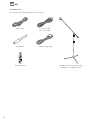
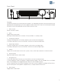
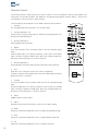
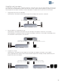
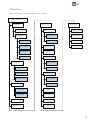
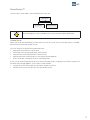
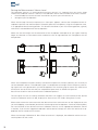
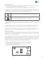
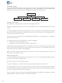
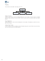
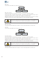
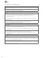
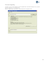
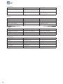
Owner´s manual
DPA-1
RoomPerfect™
DIGITAL
MUTE
ANALOG
MENU
ENTER
DPA-1 Digital Pre-Amplifier
2
Table of Contents
Operating Voltage
4
Input Name
26
Unpacking the DPA-1
4
Input Sensitivity
26
Serial Number Registration
4
Introduction
5
Accessories
6
Front Panel
7
Display Indicators
8
Rear Panel
8
27
27
27
27
27
27
28
28
28
28
28
28
29
29
30
30
31
31
31
31
Remote Control
10
Connecting the DPA-1
- Connecting to sources and amplifiers
- Using Main and Line outputs
12
12
13
Menu System
- Navigating the Menu System
14
14
Advanced Setup
- Communication
- Comm Address
- Comm Speed
- Master/Slave
- Digital Out
- Main Out
- Main Out Control
- Main Out Level
- Line Out
- Line Out Control
- Line Out Level
- Routing
- Crossover Frequency
- Filter Type
- Delay
- Trigger Setup
- Remote Control
- Firmware Versions
- Factory Reset
Menu Tree
15
RoomPerfect™ Troubleshooting
32
Introduction to RoomPerfect™
- Global Listening
- Focus Listening
- Voicing
16
16
16
16
Firmware Upgrading
33
RoomPerfect™
- Guided Setup
- Setting the Measurement Volume Level
- Focus Measurement
- Room Measurements
- Adding more Room Measurements
- Calculation of Focus 1 and Global Filters
- Advanced Options
- Measure Focus Pos.
- Measure Room Pos.
- RoomKnowledge
- RoomCorrection
17
17
18
19
19
20
21
22
22
22
23
23
Connectors
- Mains Connector
- Trigger Connector
- Optional AD Converter Board
- Balanced Inputs
- Unbalanced Inputs
34
34
34
34
34
34
Cleaning and Maintenance
34
Technical Specifications
- Audio
- Protection
- Mains
- Trigger
- Mechanical
35
35
36
36
36
36
Display
- Display Timeout
- Disp. Brightness
- Volume Disp. Timeo.
24
24
24
24
Technical Assistance
37
Appendix
- Voicing Curves
38
38
Volume
- Def. Vol.
- Max. Vol.
25
25
25
Manual version 14-05-07
3
Operating Voltage
The DPA-1 can be switched between 115V and 230V mains voltage.
In 115V mode the DPA-1 requires a mains voltage of 100V-120V at 50-60Hz.
In 230V mode the DPA-1 requires a mains voltage of 220V-240V at 50-60Hz.
The mains voltage setting for your DPA-1 can be changed on the rear selector.
Make sure the rear selector is in the correct setting and connect the power input
only to the appropiate AC source. The warranty will not cover any damage caused
by connecting to the wrong type of AC mains.
The DPA-1 has three power modes:
1. OFF
No circuitry is powered. Please note that some parts of the mains entry section still carry live mains.
2. STANDBY
The microprocessor is active.
3. ON
All circuits are active.
Unpacking the DPA-1
Carefully remove the unit and accessory kit from the carton, visually check for shipping damage.
Contact both the shipper and your Lyngdorf Audio representative immediately if the unit bears any sign
of damage from mishandeling. All Lyngdorf Audio equipment is carefully inspected before leaving our
factory.
Keep shipping carton and packing material for future use or in the unlikely event that
the unit needs servicing. If this unit is shipped without the original packing, damage
could occur and void the warranty.
Serial Number Registration
Please record the serial number of your DPA-1 here for future reference. The serial number is printed
on the label on the rear panel. You will need this serial number, should you ever require service for your
DPA-1.
DPA-1 serial number: _____________________
4
Introduction
Congratulations on the purchase of your Lyngdorf Audio DPA-1 with RoomPerfect™.
Besides being a state-of-the-art pre-amplifier, it also enables you to take advantage of the most advanced
room correction system on the market. It is implemented in such a way that you will always achieve the
perfect result. No computer needed, no acoustic knowledge needed, no user input needed. We leave
nothing to chance in the fully automated calibration process.
However, for the advanced user there are plenty of challenges since the DPA is also a complete ‘Control
Centre’ that allows you to build advanced multi-way passive or active speaker systems. This is possible
due to the very powerful built-in DSP ‘engine’ which facilitates signal routing, creation of active crossovers, delay settings etc.
In fact we believe it to be the most versatile pre-amplifier on the market today, a true state-of-the-art
device that sets new standards for what’s sonically possible to achieve in a real life environment.
5
Accessories
You should find the following accessories included:
Mains cord
8 m (26.25 feet)
XLR – XLR cable
Microphone
Programming cable
1
2
4
5
7
8
digital
0
3
6
9
info
menu
analog
AMP
RCS
CD
channel
TUNER
volume
ENTER
A/B
random
repeat
Remote control
6
Microphone stand with Mic clamp
(delivered in a separate carton)
Front Panel
DIGITAL
MUTE
ANALOG
MENU
ENTER
DPA-1 Digital Pre-Amplifier
1
2
3
4
5
6
7
8
Controls
The buttons/controls on the front panel of the DPA-1 can all be operated either with direct presses or by
operating the corresponding keys on the supplied remote control. All the keys on the front panel (except
the Mains Switch) are duplicated onto the remote control as well.
1. Mains Switch
Powers the DPA-1 on/off.
2. Mute
Toggles Mute mode on/off.
Pressing the Mute button for 3 seconds will set the DPA-1 in stand-by mode.
3. Analog Input Selector
Changes to Analog input, or if already selected, cycles to the next Analog input.
In standby mode, press to turn On the DPA-1 with the last selected analog input.
4. Digital Input Selector
Changes to Digital input, or if already selected, cycles to the next Digital input.
In standby mode, press to turn On the DPA-1 with the last selected digital input.
5. Display
Display with all information on the menu system, status, active input selection and volume control.
6. Volume Wheel
Optical encoded volume control wheel.
7. Navigation Keys
In stand by mode, press Enter to turn On the DPA-1 with the last selected input.
In normal operation mode the Up/Down toggles between bypass and the available Focus and Global
filters. The Left/Right keys toggles between neutral and the available voicings.
In menu mode the keys are used for navigation in the menu system: Up/Down, Left/Right & Enter. Pressing and holding down the Up/Down, Right/Left keys, changes selected values fast.
8. Menu Button
Toggles Menu mode on/off
7
Display Indicators
D
A
1
1
2
3
2
4
5
3
4
5
1. A-D
Illuminates to indicate whether the active input is Analog or Digital.
2. Menu
Alphanumeric Display (2*20 Characters).
3. 1-5
Illuminates the active input.
4. RoomPerfect Logo
Is illuminated when a filter is active.
5. Volume Display
3 digits indicating Volume control setting from 00.0 to 99.9 – in dB’s.
Mute is indicated by the Volume control setting ‘---’.
Standby mode is indicated with the decimal dot from the volume indicator being lit only.
Rear Panel
1
2
3
4
5
100-120V~/ 220-240V~
~50-60Hz 35W
6
7
8
9
10
11
12
1. Analog Input 1-3
Unbalanced/RCA Left/Right Analog input pairs
2. Analog Input 4
Balanced/XLR Left/Right Analog input
3. Analog Output
Double pair of balanced/XLR Left/Right analog outputs (Main and Line out).
4. Analog Output
Double pairs of unbalanced/RCA Left/Right analog outputs (Main and Line out).
8
13
5. 115V and 230V Mains Voltage Switch.
Switches between 115V and 230V mains input voltage.
Make sure the rear selector is in the correct setting and connect the power input
only to the appropiate AC source. The warranty will not cover any damage caused
by connecting to the wrong type of AC mains.
6. Digital Input 1-3
RCA connectors for SPDIF input
7. Digital Output
The digital output can be selected as the main or the line channel. In both cases the output can be selected as Full Scale or Regulated.
The sample rate is fixed at 96 kHz. This output is also active when Analog input is selected.
8. Digital Input 4
XLR Connector for AES input
9. Optical Digital Input 5
Connector for Toslink input
10. Mic. In
Mic. in for connection of RoomPerfect™ microphone.
11. Trigger Out
DC Trigger out for remote start of SDA 2175, power amplifiers or other suitable equipment with a remote
start.
The output voltage is 12V and a maximum current of 50mA can be drawn from the output.
12. RS232 Input/Aux
RS232 communication connectors for communication with a PC, remote control from other Lyngdorf
equipment with broadcast commands or linked control between several other amplifiers or other suitable
equipment with a remote start.
• The ‘INPUT’ is used for connection to a PC, or as a control input from a Lyngdorf master amplifier.
• The ‘AUX’ connection is output in Master mode for controlling slave amplifiers, or bypasses input
from other master amplifiers to the next amplifier.
13. Mains Input
9
Remote Control
The remote control is used to access the menu system as well as the buttons directly accessible on the
front panel. To control the DPA-1 the AMP key must be pressed (please note the DPA-1’s volume and
mute buttons still work when in other modes).
The functionality of the buttons when AMP is pressed are as follows:
1. Standby
The standby button puts the DPA-1 in stand-by mode.
1
1
2
3
4
5
6
7
8
9
3
digital
0
info
6
menu
9
2
2. Numerical Buttons 1-8
Selects Focus listening mode (up to 8 different listening positions can
be stored in RoomPerfect™).
4
5
3. Numerical Button 9
Selects global listening mode.
7
8
analog
12
10
AMP
RCS
CD
TUNER
13
11
4. Digital
Turns On the DPA-1 from stand-by mode in the last selected digital
input.
Selects Digital input, or if already selected, cycles to the next Digital
input. To select a specific Digital input, press the ‘Digital’ button followed by numerical button 1-5 within 2 seconds.
14
channel
16
ENTER
17
18
A/B
5. Numerical Button 0
Selects bypass listening mode (no room correction filter selected).
6. Info
Hold down for 2 seconds to show the current samplerate.
To select a specific Voicing filter, press the ‘Info’ followed by numerical
button 0-6 within 2 seconds.
7. Analog
Turns On the DPA-1 from stand-by mode with the last selected analog
input.
Selects Analog input, or if already selected, cycles to the next Analog
input. To select a specific Analog input, press the ‘Analog’ button followed by numerical button 1-4 within 2 seconds.
8. Mute
Toggles Mute function on/off.
9. Menu
Activates or de-activates the Menu system on the Main display.
10. AMP
Selects the remote for operation with a Lyngdorf Amplifier/Pre-amp.
11. RCS
Selects the remote for operation with a Lyngdorf Room Processor.
12. CD
Selects the remote for operation with a Lyngdorf CD Player.
10
volume
random
repeat
15
13. Tuner
No function.
14. Channel -/+
Toggles down/up between inputs.
15. Volume Up/down
Increases or decreases the volume in the chosen direction.
16. Up / Down / Left / Right
In normal operation mode the Up/Down toggles between bypass and the available Focus and Global
filters and the Left/Right toggles between neutral and the available voicings.
In menu mode they are used for navigation in the menu system. Pressing and holding down a key
changes selected values fast.
17. Enter
Turns the DPA-1 On from stand-by mode with the last selected input and works as Enter in menu system.
18. No Function.
11
Connecting the DPA-1
Connecting to sources and amplifiers
The DPA-1 is very simple to hook up.
1. Connect all sources to the DPA-1.
Then connect the DPA-1 output signal to a poweramplifier.
Source(s)
DPA-1 Digital Pre-Amplifier
DPA-1
Poweramp
12
Using Main and Line outputs
As described in “Routing” and “Crossover Frequency” there are many ways to utilize the Main and Line outputs. Here we have described the three most common set-up´s. Please note the products, outputs and crossover frequencies are chosen randomly in these descriptions. Combine them at your own will and needs.
1.
Single-amp set-up with no subwoofer.
A poweramp is connected to each Main Output Left and Right. No crossover is selected.
Main Output Left
No filter
Speaker
2.
Main Output Right
No filter
Poweramp
Speaker
Poweramplifier and subwoofer set-up.
A poweramp is connected to the Main Out Left and Right and highpass crossover is set at 80Hz.
The Subwoofer is connected to the Line Output and lowpass crossover is set at 80Hz. Remember to set
the subwoofer cut-off frequency to maximum.
Main Output Left + Right
Highpass filter set at 80Hz
Speakers
3.
DPA-1
DPA-1
Line Output Right
Mono lowpass filter set at 80Hz
Active subwoofer
Poweramp
Lyngdorf 2+2 setup.
A poweramp is connected to Line Output Left and Right and highpass crossover is set at 400Hz.
Two Lyngdorf boundary woofers are connected to Main Output Left and Right, through a poweramp, and
lowpass crossover set at 400Hz.
Main Output Left + Right
Highpass filter set at 400Hz
Speakers
Poweramp
DPA-1
Line Output Left + Right
Lowpass filter set at 400Hz
Poweramp
Boundary woofers
13
Menu System
The Main Display on the front panel of the DPA-1 shows all functionality and current status of the DPA-1.
An overview of the menu tree can be seen in the ‘Menu Tree’ chapter.
Navigating the Menu System
Pressing the Menu button on the front panel or the remote enters the menu or steps back one level in
the menu system.
Using the left/right arrows keys the Menu system settings can now be scrolled through. To access a sub
menu setting scroll to it and press the Enter button. To change a setting, use the Up/Down and/or Left/
Right arrows and press Enter to accept the change, or Menu to exit without applying any changes.
14
Menu Tree
This is an overview of the entire DPA-1 menu structure.
DPA -1 Main Menu
RoomPerfect
Advanced setup
Guided setup
Advanced options
Measure Focus Pos
Measure Room Pos
Communication
Remote Control
Comm Speed
Firmware versions
Master /Slave
Digital Out
RoomCorrection
Main Out
Display Timeout
Disp . Brightness
Volume Disp. Timeo.
Volume
Def. Volume
Max. Volume
Trigger setup
Comm Address
RoomKnowledge
Display
Advanced setup
Factory Reset
Main Out Control
Main Out Level
Line Out
Line Out Control
Line Out Level
Routing
Crossover freq
Input Name
Filter Type
Input Sensitivity
Delay
15
Introduction to RoomPerfect™
Once the guided set-up has been successfully completed you have the option to listen to music through
two listening settings; Focus 1 and Global room correction filters. The RoomPerfect™ filters are stored
on the numerical buttons from 1 to 9 on the remote control. To change from one filter to the other you
simply press the numerical button corresponding to the desired filter, or toggle between them by pressing the Up/Down buttons on the remote or front panel.
Global is stored on numerical button 9 and the Focus 1 is stored on numerical button 1. Furthermore you
can add 7 more Focus/listening position (8 in all). The additional focus/listening positions can be stored on
numerical buttons from 2 to 8. To bypass the room correction filters, press numerical button 0.
Global Listening
The Global filter improves the sound quality across the whole room. When you are listening to music in
a room but are not sat in any particular listening position, the global filter gives the best result.
Focus Listening
The Focus filter improves the sound quality at a listening position by exploiting the 3-dimensional acoustic properties gained through the room measurements. This makes the Focus filter the best solution for
optimal sound quality at a specific listening position.
Voicing
When using RoomPerfect™ you will experience a much more precise and detailed sound reproduction
– which could also be described as more analytical.
The Voicing setting is an EQ filter that can be used to gently amplify or attenuate certain frequencies according to your personal preferences and/or to compensate if a given recording sounds too ‘bright’ or too
‘dark’. The standard voicing settings, and their numerical value on the remote control, are:
• Neutral (0), Music 1 (1), Music 2 (2), Relaxed (3), Open (4), Open Air (5), Soft (6).
The frequency curves of the different voicing settings can be viewed in the appendix. Neutral is a bypass
setting.
You can toggle between neutral and the available voicings by pressing the Left/Right buttons on the remote or front panel. The voicings can also be chosen directly on the remote by pressing the ‘Info’ button
followed by 0-6.
16
RoomPerfect™
The sub menus accessible in the RoomPerfect™ menu are:
RoomPerfect
Guided setup
Advanced options
Advanced options is only available when Guided set-up has been performed.
Guided Setup
When you enter the RoomPerfect™ Main Menu for the first time, only the Guided setup is available.
Press Enter to initiate the guided set-up.
The main steps in the guided set-up procedure are:
• Setting the measurement volume level
• Taking one Focus (listening position) measurement
• Taking at least three room position measurements
• Adding more room measurements in the guided set-up (optional)
• Finally, automatic calculation of Focus and Global filters
If you wish to leave the guided set-up at any time during the set-up, simply press the ‘Menu ’ button and
the following message appears, ‘Exit without saving? No/Yes’.
• Choose Yes to exit the guided set-up without saving any data or,
• Choose No to cancel and continue with the guided set-up.
17
Setting the Measurement Volume Level
The calibration volume is a recommended maximum volume. It is important that you always judge
whether the calibration volume is too loud. The calibration volume should not be so loud that it causes:
•
uncomfortably loud sounds that are inconvenient to you or your environment, or
•
damage to your loudspeakers.
When the message ‘Connect and place mic. in focus pos.’ appears, connect the microphone to the microphone input found on the back panel. Thereafter, place the microphone, using the microphone stand,
in an appropriate focus/listening position. This location should be at your main listening position, typically
more or less centered between the loudspeakers.
Make sure that the height and the orientation of the microphone corresponds to your typical listening
height and direction as illustrated and do not block the line of sight between the microphone and the
loudspeakers.
When the microphone has been correctly connected and placed in the focus position, you are ready to
set the calibration volume. The calibration signal is a combination of the high and low frequency measuring signals and is only presented in your left loudspeaker. The measuring signals sound very artificial and
disharmonic due to the fact that they are composed of pure tones at different frequencies.
Press Enter to confirm and to commence the calibration process.
The test signal will start and shortly thereafter the DPA-1 will suggest an initial estimate of the desired
maximum calibration volume (in dB), displayed as ‘Desired vol. max XXdB – Retry/Save Current’
Please raise or lower the volume towards the desired maximum volume shown on the display but ensure
you avoid clipping, uncomfortably loud levels and damage to the loudspeakers. Continue choosing Retry
for a re-estimation of the desired maximum calibration volume, until an appropriate calibration volume
is reached. If you find the suggested calibration volume too loud simply turn down the volume to an appropriate level and choose Save current.
When the message ‘Calibration ok. Press Enter to continue’ is displayed, the calibration volume has successfully been set and saved.
18
Focus Measurement
When the calibration is OK, press Enter to start the measuring process and ‘Measuring Focus position
…’ will be displayed. Each measurement comprises four steps:
• A low and a high frequency measuring signal first in the left and then in the right channel.
The length of each measurement depends on a combination of the measurement volume, set in the
calibration process, and the background noise in your local environment. Typical measuring times for the
low and high frequency measuring signals are 25 and 5 seconds, respectively.
You can exit a commenced measurement by clapping close to the microphone.
Do not sit in the listening position during focus measurements.
The measurement will stop prematurely if an error occurs during the measuring process. In this case,
an error message is displayed. Press Enter to continue and ‘Retry focus measurement – press Enter’ is
displayed.
If the error needs correcting this should be done at this point (see RoomPerfect™ troubleshooting),
thereafter press Enter to retry the measurement. The measurement procedure will start again.
A measurement has ended successfully when the last measuring signal stops and the display shows a
RoomKnowledge rating, as ‘RoomKnowledge XX% - Measurement ok’. Press Enter to continue.
Room Measurements
The number of room positions needed depends on the value of RoomKnowledge, if it is below 90% after
the third measurement the guide automatically includes extra room measurements until a RoomKnowledge of 90% or more has been achieved.
The remaining measurements are to be placed in random positions in the room with random orientations of the microphone. Choosing these random or arbitrary positions and orientations is easy. All you
have to do is place the microphone at different positions in the room and with different orientations. It is
important to perform well spaced measurements to get a covering image of the acoustical properties in
the room, i.e. varying positions, heights and orientations of the microphone.
For an optimal room correction it is very important that the measurements are:
1. performed more than 1 meter (approx. 3 feet) away from the loudspeakers,
2. not performed behind the loudspeaker, and
3. that there is at least 50 cm/1.5 ft between each measurement.
2.
Not behind
loudspeaker
3.
50
cm
1.
1m
19
When a random measuring position and microphone orientation has been chosen press Enter. The measuring process will start and the display will show ‘Measuring room position 1’.
The measurement will stop prematurely if an error occurs during the measuring process. In this case, the
error message ‘Retry room measurement – press Enter’ is displayed. Press Enter to continue.
If it is an error that needs correcting, then correct the error (see ‘RoomPerfect™ trouble-shooting’ chapter)
and proceed with the room position measurement by pressing Enter. The measurement has ended successfully when the last measuring signal stops and the display shows ‘RoomKnowledge XX% - Measurement
ok’.
This process is repeated at least three times and until the RoomKnowledge reaches 90%.
Adding more Room Measurements
If you have performed successful measurements and RoomKnowledge has reached 90%, the message
‘Add more room meas.? Yes/No’ is displayed.
At this point, or any time later, you can decide whether the acquired room measurements are sufficient or
you wish to add further room measurements to learn more about the room’s acoustical information. Adding
more room measurements results in a higher RoomKnowledge, this in turn improves the room correction
filters.
• Choose Yes to add more room measurements. The room measuring process is now continued as
described in the previous section.
• Choose No when no additional measurements are required. The volume will now return to default
volume or lower, depending on the volume you have entered the guided set-up with.
The message ‘Save guided measurement - Yes/No’ will be displayed when exiting a successfully completed
guided set-up.
• Choose Yes to save the results of the guided set-up and calculate the focus and the global room
correction filters.
• Choose No if you wish to exit the guided set-up without calculating any room correction filters, without
saving the performed measurements and without setting the calibration volume.
20
Calculation of Focus 1 and Global Filters
When RoomPerfect™ calculates the filters the display shows the following, ‘Calculating filters - Please
wait’.
The filter calculation process can be expected to take anywhere between 5 seconds and a minute depending on the specific task.
When RoomPerfect™ has calculated the room correction filters, they are automatically saved. The Focus
filter is saved as setting 1 and Global is saved as setting 9 out of the possible 9 filter settings.
You have now successfully completed a guided set-up and the RoomPerfect™ Advanced Menu is now
available.
21
Advanced Options
This section describes the options in the advanced menu, which is available after Guided Setup has been
completed. Here you can add new listening positions and room measurements, check the RoomKnowledge of your current set-up, and check the RoomCorrection for the different filters.
Advanced options
Measure Focus Pos
Measure Room Pos
RoomKnowledge
RoomCorrection
Measure Focus Pos.
As mentioned, it is possible to add 7 different listening/focus positions.
Place the microphone correctly in the new listening position and the measurement process can commence.
The saved calibration volume from the guided set-up is used as a default when adding extra focus/listening and room positions though, as mentioned, the volume can be changed at any time between measurements to suit a particular situation.
After a successful measurement the message ‘RoomKnowledge XX% - Measurement ok’ is displayed.
Press Enter to continue.
The message ‘Save Focus measurement(s) – Yes/No’ will appear.
• choose Yes to save the measurement or,
• choose No to exit without saving the current measurement.
Choose between focus/listening position 2 - 8 and press Enter. If you wish to overwrite an existing Focus
filter (2 to 8 can be overwritten) or you are trying to save a new filter on an existing preset then ‘Focus
no.X exists! Overwrite? Yes/No’ will be displayed.
When the Focus number has been chosen, the volume turns down to default or lower and the new
Focus filter is calculated and saved.
Measure Room Pos.
It is always possible to add more room measurements, which can increase RoomKnowledge and thereby fine tune all the room correction filters.
Press Enter to start a new room measurement.
Place the microphone in a random room position and the measurement can commence.
The saved calibration volume from the guided set-up is used as default when adding extra focus/listening
and room positions, though as mentioned, the volume can be changed at any time between measurements to suit a particular measurement situation.
After a successful room measurement the RoomKnowledge is re-calculated and displayed as ‘RoomKnowledge XX% - Measurement X ok’. Press Enter to continue.
22
‘Add more room meas.? Yes/No’ will show in the display:
• choose Yes to add another room measurement or,
• choose No to stop adding more room measurements. If No is chosen the volume is returned to
the default or lower.
‘Save room measurement(s)? Yes/No’ will hereafter be shown.
• choose Yes to save the performed room measurement,
• and No to exit without saving any of the performed measurements.
Adding one or more room measurements leads to a re-calculation of all filters (i.e. Global and all Focus
filters) due to the fact that more of room’s acoustic properties have been learned, something that affects
all filters.
RoomKnowledge
The RoomKnowledge index is a parameter that tells how much of the room’s acoustical properties have
been learned. A high RoomKnowledge ( 90%) means that most of the room’s acoustical properties have
been learned. The more room measurements you add, the higher the RoomKnowledge will become.
The more that the acoustical properties of the room are learned, the greater the accuracy of the room
correction.
RoomCorrection
The RoomCorrection index is a measure of how much processing is being employed in the room correction filters. To some extent the RoomCorrection index reflects how audible the correction is. However, the same amount of processing can sound very different due to placement in frequency of the
processing. For low values (below 10%) of the room correction index, only subtle correction is needed
to the original sound in the room. With high room correction index values more extensive processing is
employed.
The RoomCorrection index for a specific RoomPerfect™ filter can be viewed by pressing the numerical
button of the corresponding filter. This can only be done while in the RoomCorrection menu.
To see a short video presentation of RoomPerfect™, please go to www.lyngdorf.com.
23
Display
The sub menus accessible in the Display menu are:
Display
Display Timeout
Disp. Brightness
Volume Disp.Timeo.
Display Timeout
Display Timeout set-up is used for enabling/disabling the 10 sec. display ’switch’off’ feature. If enabled
the Main Display reading will switch off after 10 sec of inactivity from the remote control or front panel
buttons.
Disp. Brightness
Display Brightness is used to control the brightness of the display. The brightness can be set to 25%,
50%, 75% or 100%.
Volume Disp. Timeo.
If Volume Display Timeout is enabled the Volume Display reading will switch off after 10 sec of inactivity
from the remote control or front panel buttons.
24
Volume
The sub menus accessible in the Volume menu are:
Volume
Def. Volume
Max. Volume
Def. Vol.
The Default Volume setting controls the default volume at start-up and can be set from 0 to 99 dB.
However, a setting over 88 is not recommended as this corresponds to max output with full scale digital
input.
Max. Vol.
The Maximum Volume setting is a safety precaution used for limiting the maximum volume which can be
achieved by spinning the wheel or increasing volume via the remote. This can be set to avoid excessively
loud sound pressure levels and/or to protect your loudspeakers against overload.
25
Input Name
Input Name
As default, digital inputs are called Digital 1-5 and Analog inputs are called Analog 1-4. To change the
name, choose an input and then between the following preset names:
• ADC, Analog 1-4, AUX, CD, CD-1, CD-2, DAB, DAT, DBS, DCC, Digital 1-5, DVD, DVD-1, DVD-2, FM, LD,
MD, PC, PHONO, RADIO, RIAA, SACD, SAT, TAPE, TUNER, TV, VCR, VDP, VIDEO, VIDEO-1,
VIDEO-2.
Input Sensitivity
Input Sensitivity
The Input Sensitivity adjustment enables you to match levels from different sources as well as obtaining
full scale output on your amplifier. The Sensitivity can be adjusted +/-12dB in 0.1 dB steps.
Setting the Input Sensitivity too high will result in clipping/distortion. Therefore,
always use your ears when setting the Input Sensitivity
26
Advanced Setup
The sub menus accessible in the Advanced menu are:
Advanced setup
Communication
Main Out
Crossover freq
Trigger setup
Master /Slave
Line Out
Filter Type
Remote Control
Digital Out
Routing
Delay
Firmware versions
Factory Reset
Communication
The sub menus accessible in the Communication menu are:
Communication
Comm Address
Comm Speed
Comm Address
The Communication Address setting identifies the DPA-1’s to the PC interface or other Lyngdorf products. In master mode the DPA-1 setting is normally 1, and the addresses 2-99 can be used for individual
slave pre-amplifiers, but nothing is restricted. The PC software must know the address of the DPA-1 in
order to communicate with it.
Comm Speed
The Communication Speed setting is the RS232 Link interface speed. The default setting is 57600 baud.
With different PC’s and different lengths of cables the settings can be changed to 9600 or 115200 baud.
If a multi-amplifier set-up is installed with Master/Slave communication, a smaller delay can be observed
when using higher speeds.
Master/Slave
Master/Slave
As default a DPA-1 is set as a Slave. If set as a Master the DPA-1 will control the connected applicable
equipment, e.g. when adjusting the volume control and when switching on and off.
If updating firmware the DPA-1 must be set in Slave mode in order to communicate with the PC.
Digital Out
Digital Out
It is possible to select if the Digital Output should be the same channel as Main or the same as Line
Out.
The Digital Out will have different functions, depending of the setup for Main Out, Line Out and crossover.
27
Main Out
The sub menus accessible in the ‘Main Out’ menu are:
Main Out
Main Out Control
Main Out Level
Main Out Control
The Main Out Control sets the output level to be Full Scale (fixed) or Regulated (variable).
Fixed means there’s a constant full scale output – most often used as ‘tape out’ or when using a
Lyngdorf Audio TDAI or SDAI as a second ‘slave’ amplifier in a bi-amping set-up.
Regulated (variable) means that the output level will follow the level of the volume control. This setting
is chosen if you have, for instance, a power amplifier or an active subwoofer connected.
If Full Scale is selected you will constantly have full output – with huge potential for
overload and damage of power amplifier and/or loudspeakers if connected.
Main Out Level
This adjusts the overall output level in steps of - 0.1 db, it can be attenuated to – 40 dB in total.
Line Out
The sub menus accessible in the ‘Line Out’ menu are:
Line Out
Line Out Control
Line Out Level
Line Out Control
The Line Out Control sets the output level to be Full Scale (fixed) or Regulated (variable).
Fixed means there’s a constant full scale output – most often used as ‘tape out’ or when using a
Lyngdorf Audio TDAI or SDAI as a second ‘slave’ amplifier in a bi-amping set-up.
Regulated (variable) means that the output level will follow the level of the volume control. This setting
is chosen if you have, for instance, a power amplifier or an active subwoofer connected.
If Full Scale is selected you will constantly have full output – with huge potential for
overload and damage of power amplifier and/or loudspeakers if connected.
Line Out Level
This adjusts the overall output level in steps of - 0.1 db, it can be attenuated to – 40 dB in total.
28
Routing
Routing
In Routing it is possible to apply different settings to the Main and Line outputs:
Symbol
Name
Main output
Line Output
R
L
Highpass filter
X
X
R
L
Lowpass filter
X
X
R L
L R
Left and Right channel switching
X
-
M
Mono
-
X
M
Mono lowpass filter
X
A highpass and lowpass filter can be applied to the Main and Line outputs when you want to connect an
additional amplifier or subwoofer together with your main loudspeakers.
A Mono setting is also available for the Line output, this is used when connecting a single subwoofer to
just one Line output.
If no filter is selected the full frequency range will be directed to your main loudspeakers. If a filter is
selected the frequencies above or below the selecter crossover frequency will be directed through the
analog line-out and digital Line Out or Main Out terminals.
When a highpass or lowpass filter has been chosen, the Crossover Frequency and Filter Type menus are
enabled.
Crossover Frequency
Crossover freq.
Crossover Frequency is only available when Routing has been setup.
The Crossover Frequency can be selected anywhere between 40 – 9999Hz.
It is very difficult to give exact guidelines to setting a suitable crossover frequency, filter type and order
since this depends on the exact drivers and configurations. Therefore, the following recommendations
should be seen as a good starting point only.
29
In general, the recommended crossover frequency between (sub)woofers and main speakers is between 200 - 400 Hz.
By using a high crossover frequency, the rear wall quarter wavelength reflection is removed from the
main speakers.
If a Lyngdorf Audio boundary woofer is used in a 2+2 set-up, a crossover frequency of 400 is recommended due to the high bandwidth of the boundary woofer.
For conventional active subwoofers with built in low pass filter the recommended crossover frequency
is the upper low-pass frequency of the subwoofer.
If at all possible, the low pass filter in the subwoofer should be bypassed. Due to the quarter wave
reflection from the rear wall corresponding to the depth of the subwoofer cabinet we recommend an
crossover point at approximately 200 Hz. You might experiment with turning the subwoofer so the driver
faces the wall in a distance of 5 to 10 cm. This will increase the bandwidth of the subwoofer.
However, due to the limited bandwidth (frequency response) of most conventional subwoofers you
might find it necessary to choose a lower crossover frequency.
When ‘building’ active speaker systems it is recommended to use the original crossover point(s) used
by the manufacturer. Due to the short wavelengths of the mid/high frequencies it is essential that both
crossover frequency, filter type and order as well as delay is set correctly. Therefore, creating filters for
active speakers is an iterative process that requires several critical listening sessions in order to achieve
seamless integration of the different speaker drivers.
Filter Type
Filter Type
Filter Type is only available when Routing has been setup.
It is possible to choose from two different Filter Types in this menu.
LiRi: (Linkwitz Riley) 2, 4 or 8 order.
Butw: (Butterworth) 1, 2 or 4 order.
In a 2+2 set-up (main speakers + Lyngdorf Audio boundary woofers) we recommend using a fourth order
Linkwitz Riley filter.
In set-ups using conventional active subwoofers – again due to limited bandwidth – we recommend using a second order butterworth filter.
In active speaker systems it is recommended starting with a fourth order Linkwitz Riley filter.
Delay
Delay
If you are using a set-up with two main loudspeakers located at an identical distance to the listening
position you don’t need to set a delay. However, if the distance isn’t identical and/or you are using a subwoofer, or a Lyngdorf Audio 2+2 system, you need to set a delay in order to ensure that the sound from
each loudspeaker reaches the listening position simultaneously. This must be done for main left (ML) and
right (MR) and as well as line left (LL) and right (LR).
To set the delay all you need to do is measure the distance from each loudspeaker to the listening position and enter these values in the menu. The necessary delays are then automatically calculated and
applied to each channel.
30
1 centimeter = 0.3937 in
The fault message ‘Values for delay exceed limits’ is displayed when the difference
between the distance from the speakers closest to, and the speakers furthest from,
the listening position is too big. The biggest difference allowed is 340 cm / 134 in.
If the fault message appears, you can use the following solutions:
(Can be used individually or together to achieve a valid set-up with respect to the delay lengths):
• Shorten the distances between your Main and Line channel loudspeakers resulting in a more
compact loudspeaker set-up.
• Arrange your loudspeaker set-up and/or your listening position in a more symmetrical set-up.
Trigger Setup
Trigger setup
Trigger setup sets the usage of the trigger output option. If e.g. SDA2175 is connected to drive a subwoofer from the Line out, the trigger can be activated and used for switching the SDA2175 On and
Off.
Remote Control
Remote Control
Remote Control set-up makes it possible to activate or de-activate the remote control.
Firmware Versions
Firmware versions
The Firmware Versions menu is used to check the current firmware version of your DPA-1 and the RoomPerfect™ module as well as the RoomPerfect™ serial number.
Factory Reset
Factory Reset
The Factory Reset setting is used to restore all settings, including RoomPerfect, in the DPA-1 to the factory settings.
If you return to the factory settings all your personal settings will be erased.
31
RoomPerfect™ Troubleshooting
No microphone connected
The error message ‘No microphone connected’ is displayed when no microphone is connected to the
DPA-1.
Solution:
• Connect the microphone on input on the back panel.
No signal
1. The error message ‘Fault – No signal’ is displayed when the incoming signal is classified as
pure noise. This happens when the measuring signal is too low compared with the noise
from the local environment. This could be due to there being too much noise in your
measuring environment.
2. The above error message is also displayed when the loudspeakers are not connected and/or
Mute is activated.
Solution:
• Raise the measuring signal volume before continuing with the measurement.
• Connect your loudspeakers and/or de-activate Mute.
Signal clipping
1. The error message ‘Fault – Signal clipping’ is displayed when the incoming signal is
classified as too loud resulting in clipping (distortion).
2. A loud noise from the local environment that has corrupted the measurement results in this
error message.
Solution:
• Lower the measuring signal volume before continuing with the measurement.
• Repeat the measurement with no changes; however refrain from making excessive noise
when measuring.
Low signal
The error message ‘Fault – Low signal’ is displayed when the measurement has taken more than 5
minutes for the low frequency signal or 2 minutes for the high frequency signal. This happens most
often when using a low measuring signal compared to the background noise of your environment,
something that results in prolonged measuring times.
Solution:
• Raise the measuring signal volume before continuing with the measurement, or reduce the
noisy elements in your environment.
32
Firmware Upgrading
The DPA-1 firmware can be upgraded using the ‘Lyngdorf Audio – Serial Load’ software. This is in the PC
package available from www.Lyngdorf.com.
Follow the upgrade steps shown below to bring the product into upgrade mode.
33
Connectors
Mains Connector
Mains voltage to the DPA-1 is applied via an IEC320 type connector. The supplied cable with safety
ground should be used to connect the DPA-1 to a mains outlet.
Make sure the rear selector is in the correct setting and connect the power input
only to the appropiate AC source. The warranty will not cover any damage caused
by connecting to the wrong type of AC mains.
Always disconnect the DPA-1 from the mains before changing any connections to
its inputs or outputs.
Trigger Connector
The DPA-1 is equipped with a TRIGGER OUT 3.5mm mono jack connector. The trigger signal is a 12V
short circuit-protected output signal for powering up external equipment when the DPA-1 is on, e.g. remotely connected SDA 2175 power amplifiers or active subwoofers.
AD Converter Board
The AD Converter card for the DPA-1 has input connectors for both balanced (XLR) and unbalanced (RCA)
analog signals. The input impedance of the inputs are 10 kOhm.
Balanced Inputs
The balanced XLR inputs are wired in accordance with IEC268:
Pin 1: Chassis and ground.
Pin 2: Hot (+).
Pin 3: Cold (-).
Shell: Chassis and ground.
Unbalanced Inputs
The unbalanced RCA inputs are wired in accordance with normal practice:
Shell: Chassis and ground.
Pin: Hot (+).
Cleaning and Maintenance
This unit does not require any regular maintenance except to keep its exterior clean. Simply wipe its exterior with a clean soft cloth. A small amount of non-abrasive cleaner may be used on the cloth to remove
any excessive dirt or fingerprints. Do not use abrasive cleaners or cleaners containing liquid solvents.
34
Technical Specifications
Audio
Parameter
Value
Note
Balanced input connectors
3 pin XLR, gold-plated.
Case=Gnd, Pin1=Gnd,
Pin2=Hot(+), Pin3=Cold(-)
Balanced input impedance
10KOhm
AC-coupled.
Unbalanced input connectors
RCA (phono) jack, gold-plated.
Case=Gnd, Tip=Hot(+)
Unbalanced input impedance
10KOhm
AC-coupled
DAC Out impedance
50Ohm
Gain According to volume control setting. 88 dB = 0 dB with
sensitivity normal and rel.
volume 0 dB
Input sensitivity
4.4V (2.2V with high sens.)
Unbalanced output
4.4Vrms
Balanced output
8.8Vrms
Frequency Response 20 - 20KHz +/-0.1dB
RoomPerfect Highpass Filter
-3dB at 18Hz
THD+N A-wgt
Digital to Analog
-103dB
Neutral voicing - ref 4.4V
S/N Ratio
Digital to Analog
-113dB
Neutral voicing - ref 4.4V
Dynamic Range
Digital to Analog
-113dB
Neutral voicing - ref 4.4V
THD+N A-wgt
Analog to Digital
-110dB
Neutral voicing - ref 4.4V
S/N Ratio
Analog to Digital
-119dB
Neutral voicing - ref 4.4V
Dynamic Range
Analog to Digital
-119dB
Neutral voicing - ref 4.4V
THD+N A-wgt
Analog to Analog
-103dB
Neutral voicing - ref 4.4V
S/N Ratio
Analog to Analog
-113dB
Neutral voicing - ref 4.4V
Dynamic Range
Analog to Analog
-113dB
Neutral voicing - ref 4.4V
Channel Separation
-114dB
AC Sweep from 125 - 16KHz
All audio measurements, except frequency response, are measured with a 20KHz low-pass filter in
accordance with AES-17.
35
Protection
Parameter
Value
Note
Grounding
Mains earth, chassis and audio
ground are connected internally.
Over temperature
Mains-transformer.
Auto resetting thermal fuse in
mains transformer.
Parameter
Value
Note
Mains input connector
IEC 320 cold type
Mains lead supplied.
Mains voltage range
100-240V AC, 50–60Hz
Power consumption
4W
STANDBY mode.
Power consumption
35 W
OPERATE mode
Parameter
Value
Note
Trigger Out connector
3.5mm (1/8”) mono jack
Case=Gnd, Tip=Input
Trigger Out voltage
12V DC
Short circuit protected
Trigger Out Current
50mA
Mains
Trigger
Mechanical
36
Parameter
Value
Width
450mm (17.72”)
Depth
440mm (17.32”)
Height
100mm (3.94”)
Net weight
7.4Kg (16lb.)
Shipping weight
10.8Kg (23.8 lb.)
Note
Including feet.
Two shipping boxes.
Technical Assistance
For latest version of the firmware, newest version of this document and ‘Questions and Answers’,
please check the ‘Support’ section on the Lyngdorf Audio website.
If you have any problems with or questions regarding your Lyngdorf Audio product, please contact
your nearest Lyngdorf Audio representative or:
Lyngdorf Audio ApS
Denmark
E-mail: [email protected]
Web: http://www.lyngdorf.com
37
Appendix
Voicing Curves
For further information on the Voicing setting, please refer to the “Voicing” chapter.
Music 1
Music 2
Ma gnitude R esponse: Music 2
6
4
4
2
2
Magnitude (dB )
Magnitude (dB )
Ma gnitude R esponse: Music 1
6
0
-2
0
-2
-4
-4
-6
-6
10 Hz
100 Hz
1kHz
10kHz
10 Hz
100 Hz
F requency (Hz)
Relaxed
6
6
4
4
2
2
Magnitude (dB )
Magnitude (dB )
Ma gnitude R esponse: Open
0
-2
-4
0
-2
-4
-6
-6
10 Hz
100 Hz
1kHz
10 Hz
10kHz
100 Hz
1kHz
10kHz
F requency (Hz)
F requency (Hz)
Soft
Open Air
Ma gnitude R esponse: S oft
Ma gnitude R esponse: Open Air
6
6
4
4
2
2
Magnitude (dB )
Magnitude (dB )
10kHz
Open
Ma gnitude R esponse: R ela x ed
0
-2
-4
0
-2
-4
-6
-6
10 Hz
100 Hz
1kHz
F requency (Hz)
38
1kHz
F requency (Hz)
10kHz
10 Hz
100 Hz
1kHz
F requency (Hz)
10kHz
39
www.lyngdorf.com
40