1
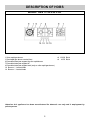
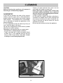
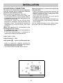
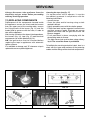
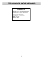
INSTRUCTIONS AND
RECOMMENDATIONS FOR THE USE,
INSTALLATION AND MAINTENANCE OF
BUILT-IN GAS CERAMIC HOBS
Dear customer,
thank you for buying one of our products.
We are sure that this new, modern, functional and practical appliance, made using the finest quality
materials, will fully satisfy your requirements. This new appliance is very easy to use, but in order to
obtain the best results, we strongly recommend that you read this booklet carefully before use.
These instructions are valid exclusively for countries the identification symbols of which appear
on the cover of the instruction booklet and the label on the appliance.
The manufacturer cannot be considered responsible for any damages to people or to things in the
event of incorrect installation or improper use of the appliance.
Kuppersbusch USA
1883 Massaro Blvd. Tampa, FL 33619
Toll: (800) 459-0844 P: 813-288-8890 F: 813-288-8604
MODEL:
GKS 11742.0-35 F-UL
The Manufacturer cannot be held responsible for any imprecision due to printing or copying errors
contained in this booklet. The figures shown are purely indicative. We reserve the right to make any
changes to our products which we consider to be necessary or useful, also in the interest of the user,
without affecting their essential characteristics in terms of functionality and safety.
COD. 04059ULKUP - 04.06.2009
DESCRIPTION OF HOBS
MODEL: GKS 11742.0-35 F-UL
1 Ultra rapid gas burner
3 Semirapid gas burner central front
6 Enamelled steel pan support for ultra rapid burner
7 Enamelled steel pan support 2F
8 Enamelled steel pan support wok (only on ultra rapid gas burner)
10 Burner n° 1 control knob
12 Burner n° 3 control knob
of 10300 Btu/h
of 4350 Btu/h
Attention: this appliance has been manufactured for domestic use only and it employment by
private person.
2
SAFE GUARD INSTRUCTIONS
1) SAFE GUARD INSTRUCTIONS
For all appliances:
- the product shall be installed according with the a statement that the installation must conform with local
codes or, in absence of local codes, with the National Fuel Gas Code, ANSI Z223.1/NFPA 54.
- The product must be electrically grounded in accordance with local codes or, in the absence of local codes,
with the National Electrical Code, ANSI/NFPA 70.
- The appliance and its individual shutoff valve must be disconnected from the gas supply piping system
during any pressure testing of that system at test pressure in excess of ½ psi (3.5 kPa). The maximun
gas supply pressure is 4 inch WC and 11 inch WC and the gas pressure regulator provided is regulated to
1 inch water column above the manufacturer’s specified manihold pressure.
- Always disconnect all cord connect appliances shall include instructions relative to location ot the wall
receptacle and the warning to the user to disconnect the electrical supply before servicing the appliance.
WARNING: If the information on this manual is not followed
exactly, a fire or explosion may result causing property
damage, personal injury or death.
- Do not store or use gasoline or other flammable vapors and liquids in the vicinity of this or any
other appliance.
- WHAT TO DO IF YOU SMELL GAS
- Do not try to light any appliance.
- Do not touch any electrical switch; do not use any phone in your building.
- Immediately call your gas supplier from a neighbor’s phone.
Follow the gas supplier’s instructions.
- If you cannot reach your gas supplier, call the fire department.
- Installation and service must be performed by a qualified installer; service agency or the
gas supplier.
- Save the orifices removed from the appliance for future use.
- When a flexible service cord of the grounding type is provided to connect the appliance to a line-voltage
electrical supply, the instructions shall also include the intent of the warning statement specified in 1.29.12.
- The maximum depth cabinets installed above cooking tops be 13 in. (330 mm).
- Keeping appliance area clear and free from combustible materials, gasoline, and other flammable vapors
and liquids.
- Not obstructing the flow combustion and ventilation air.
3
USE
2) BURNERS
Burners
A diagram is screen-printed above each knob on
the front panel. This diagram indicates to which
burner the knob in question corresponds. After
having opened the gas mains or gas bottle tap, light
the burners as described below:
- manual ignition
Push and turn the knob corresponding to the
required burner in an anticlockwise direction until it
reaches the full on position (large flame fig. 1), then
place a lighted match near the burner.
- Electrical ignition
Push and turn the knob corresponding to the
required burner in an anticlockwise direction until it
reaches the full on position (large flame fig. 1), then
depress and release the ignition button “E”.
- Automatic electrical ignition
Push and turn the knob corresponding to the
required burner in an anticlockwise direction until it
reaches the full on position (large flame fig. 1), then
depress the knob.
- Lighting burners equipped with flame failure
device
The knobs of burners equipped with flame failure
device must be turned in an anticlockwise direction
until they reach the full on position (large flame fig. 1)
and come to a stop. Now depress the knob in
question and repeat the previously indicated
operations.
Keep the knob depressed for about 10 seconds
once the burner has ignited.
HOW TO USE THE BURNERS
Bear in mind the following indications in order to
achieve maximum efficiency with the least possible
gas consumption:
- use adequate pans for each burner (consult the
following table and fig. 2).
- When the pan comes to the boil, set the knob to
the reduced rate position (small flame fig. 1).
- Always place a lid on the pans.
- Use only pan with a flat bottom.
Ultra rapid
Semirapid
Power ratings
Pan Ø in cm
4350 Btu/h
16 ÷ 18
10300 Btu/h
24 ÷ 26
WARNINGS:
- burners with flame failure device may only be
ignited when the relative knob has been set to
the Full on position (large flame fig. 1).
- Matches can be used to ignite the burners in a
blackout.
- Never leave the appliance unattended when
the burners are being used. Make sure there
are no children in the near vicinity. Particularly
make sure that the pan handles are correctly
positioned and keep a chek on foods requiring
oil and grease to cook since these products
can easily catch fire.
- The machine must not be used by people
(including children) with impaired mental or
physical capacities, or without experience of
using electrical devices, unless supervised or
instructed by an expert adult responsible for
their care and safety. Children should not be
allowed to play with the equipment.
- Never use aerosols near the appliance when it
is operating.
- If the built-in hot plate has a lid, any spilt food
should be immediately removed from this
before it is opened. If the appliance has a glass
lid, this could shatter when the hot plate
becomes hot. Always switch off all the burners
before closing the lid.
- Containers wider than the unit are
recommended.
FIG. 1
FIG. 2
4
USE
Notes:
use of a gas cooking appliance produces heat and moisture in the room in which it is installed.
The room must therefore be well ventilated.
Intensive and lengthy use of the appliance may require additional ventilation. This can be
achieved by opening a window or by increasing the power of the mechanical exhausting system if
installed.
WARNING!
NEVER use this appliance as a space heater
to heat or warm the room. Doing so may result
in carbon monoxide poisoning and
overheating ot the oven.
5
CLEANING
CAUTION:
before cleaning the appliance, disconnect it
from the gas and electricity supplies.
- Traces of liquid spilled from pans can be
eliminated with vinegar or lemon juice.
- Never allow sugar or sugary foods to fall on the
hob while cooking. Should this occur, switch off
the hob and clean it immediately with hot water,
using a scraper on hot spills.
- As time goes by metallic reflections, colouring or
scratches may appear due to poor cleaning and
the incorrect movement of pans. Scratches are
hard to eliminate but do not affect the correct
operation of your hob.
- Do not use jets of steam to clean the appliance.
3) WORKTOP
If you wish to maintain the shine of the ceramic
surface, treat the glass with a silicon-based film
product before use to protect the surface against
water and dirt. This protective film is not durable,
so it is advisable to repeat the application of the
product frequently.
It is very important to clean the hob every time you
use it, while the glass is still warm.
Do not clean using abrasive metal scourers, powder
abrasives or corrosive sprays.
Depending on the degree of dirt, we recommend:
- for light stains, a damp sponge is sufficient.
- Tough, encrusted dirt is easily eliminated using a
scraper (fig. 3), not supplied with the hob, but
easy to find in local stores. Use the scraper
carefully to avoid damaging the hob.
FIG. 3
6
CLEANING
- If the opening and closing of any valve is
awkward, do not force it but request urgent
intervention by the technical assistance
service.
- Do not use jets of steam to clean the
appliance.
- To prevent difficulties with lighting, regularly
clean the ignition elements (ceramic and
electrode) and safety cut-off devices.
The enamelled grids, enamelled covers “A”, “B” and
“C”, and burner heads “M” (see fig. 4 and 4/A) must
also be washed and the ignition elements “AC” and
safety cut-off sensors “TC” (see fig. 5) must be
cleaned. Do not wash them in the dishwasher.
Cleaning operations must be carried out when the
hob and components are not hot and the use of
metal scouring pads, powder abrasives and
corrosive sprays must be avoided.
Do not allow vinegar, coffee, milk, salt water, lemon
juice or tomato juice to remain in prolonged contact
with the surfaces.
WARNINGS:
when reassembling the components, observe
the following recommendations:
- check that the holes in the burner heads “M”
(fig. 4) are not blocked by foreign bodies.
- Ensure that the enamelled covers “A”, “B”
and “C” (fig. 4 and 4/A) are correctly
positioned on the burner head. The covers are
correctly positioned on the head when they
are perfectly stable.
FIGURE 1
FIG. 4
FIG. 4/A
FIG. 5
7
INSTALLATION
TECHNICAL INFORMATION
FOR THE INSTALLER
5) FIXING THE HOT PLATE
The hot plate has a special seal which prevents
liquid from getting into the cabinet. Strictly comply
with the following instructions in order to correctly
apply this seal:
- detach the seals from their backing, checking
that the transparent protection still adheres to the
seal itself.
- Evenly and securely fix the seal to the hot plate,
pressing into place with the fingers and remove
the strip of protective paper from the seal and set
the plate into the hole made in the cabinet.
- The prospective walls (left or right) that exceed the
working table in height must be at a minimum
distance from the cutting as mentionned both in
the columns and the scheme.
- In order to avoid accidental touch with the
overheating bottom of the hob, during the
working, is necessary to put a wooden insert,
fixed by screws, at a minimum distance of
150 mm from the lower surface of the top
(see fig. 6).
Installation, adjustments of controls and
maintenance must only be carried out by a
qualified engineer.
Incorrect installation may cause damage to
persons, animals or property for which the
Manufacturer shall not be considered responsible.
During the life of the system, the automatic
safety or regulating devices on the appliance
may only be modified by the manufacturer or by
his duly authorized dealer.
4) INSTALLING THE WORKTOP
Check that the appliance is in a good condition after
having removed the outer packaging and internal
wrappings from around the various loose parts. In
case of doubt, do not use the appliance and contact
qualified personnel.
Never leave the packaging materials (cardboard,
bags, polystyrene foam, nails, etc.) within
children’s reach since they could become
potential sources of danger.
The measurements of the opening made in the top of
the modular cabinet and into which the hot plate will be
installed are indicated in either fig. 6. Always comply
with the measurements given for the hole into which
the appliance will be recessed (see fig. 6 and 7).
COMPLY WITH THE
DIMENSIONS (mm)
4F (110)
A
B
C
D
E
1060
345
80 min
127.5
75 min
FIG. 6
FIG. 7
8
INSTALLATION
6) ROOM VENTILATION
The transition piece on the supply side of the
regulator must be provided by the installer.
Unions compatible with the hose fittings must be
used and connections tested for gas leaks.
Ensure the supply connection point is accessible
with the appliance installed.
Warning: ensure that the hose assembly is
restrained from accidental contact with the flue or
flue outlet of an underbench oven.
To ensure correct operation of the appliance, it is
important to ensure that the room where the hot
plate is installed has sufficient ventilation.
7) GAS CONNECTION
Natural Gas and Propane Gas
Natural Gas installations require the connection of
a gas regulator at the appliance. This regulator is
supplied with the appliance on purchase.
Assemble the regulator (noting the gas flow
direction) and transition pieces (supplied with the
appliance), in accordance with below figure.
9
INSTALLATION
8) ELECTRICAL CONNECTION
When the appliance is connected straight to the
electricity main:
- install an omnipolar circuit-breaker between the
appliance and the electricity main. This circuitbreaker should be sized, in compliance with
current installation regulations.
- Remember that the earth wire must not be
interrupted by the circuit-breaker.
- For optimum safety, the electrical connection may
also be protected by a high sensitivity differential
circuit- breaker.
You are strongly advised to fix the relative yellowgreen earth wire to an efficient earthing system.
The electrical connections of the appliance
must be carried out in compliance with the
provisions and standards in force.
Before connecting the appliance, check that:
- the electrical capacity of the mains supply and
current sockets suit the maximum power rating of
the appliance (consult the data label applied to the
underside of the hot plate).
- The socket or system has an efficient earth
connection in compliance with the provisions and
standards in force. The manufacturer declines all
responsibility for failing to comply with these
provisions.
When the appliance is connected to the
electricity main by a socket:
- fit a standard plug suited to the load indicated on
the data label to the cable.
- Fit the wires following figure 8, taking care of
respecting the following correspondences:
Letter L (live) = wire;
Letter N (neutral) = wire;
earth symbol
= green or yellow-green wire.
- Never use reductions, adapters of shunts for
connection since these could create false contacts
and lead to dangerous overheating.
- The outlet must be accessible after the built-in.
FIG. 8
10
INSTALLATION
9) FIXING THE HOT PLATE
- Fix the hob with the proper brackets “S” and turn
the screw “F” until the bracket “S” stick on the top
(fig. 10).
- The prospective walls (left or right) that exceed the
working table in height must be at a minimum
distance from the cutting as mentionned both in
the columns and the scheme.
- In order to avoid accidental touch with the
overheating bottom of the hob, during the working,
is necessary to put a wooden insert, fixed by
screws, at a minimum distance of 150 mm from
the lower surface of the top (see fig. 6).
The hot plate has a special seal which prevents
liquid from infiltrating into the cabinet. Strictly
comply with the following instructions in order to
correctly apply this seal:
- detach the seals from their backing, checking that
the transparent protection still adheres to the seal
itself.
- Overturn the hot plate and correctly position seal
“E” (fig. 9) under the edge of the hot plate itself, so
that the outer side of the seal perfectly matches
the outer perimetral edge of the hot plate. The
ends of the strips must fit together without
overlapping.
- Evenly and securely fix the seal to the hot plate,
pressing into place with the fingers and remove
the strip of protective paper from the seal and set
the plate into the hole made in the cabinet.
FIG. 9
FIG. 10
11
ADJUSTMENTS
Always disconnect the appliance from the
electricity main before making any adjustments.
All seals must be replaced by the technician at
the end of any adjustments or regulations.
Our burners do not require primary air
adjustment.
- Insert a small screwdriver “D” into hole “C” (fig. 11)
and turn the throttle screw to the right or left until
the burner flame has been adequately regulated to
the “Reduced rate” position.
Check that the flame does not go out when the
knob is sharply switched from the “Full on” to the
“Reduced rate” position.
10) TAPS
It is understood that only burners operating
with Natural Gas or Town gas should be
subjected to the above mentioned adjustments.
The screw must be fully locked when the
burners operate with Propane HD-5 (turn
clockwise).
“Reduced rate” adjustment
- Switch on the burner and turn the relative knob to
the “Reduced rate” position (small flame fig. 1).
- Remove knob “M” (fig. 11) of the tap, which is
simply pressed on to its rod.
FIG. 11
12
CONVERSIONS
11) REPLACING THE INJECTORS
paragraphs 10. The technician must reset any
seals on the regulating or pre-regulating devices.
The envelope with the injectors and the labels can
be included in the kit, or at disposal to the
authorized customer Service Centre.
For the sake of convenience, the nominal rate table
also lists the heat inputs of the burners, the
diameter of the injectors and the working pressures
of the various types of gas.
The burners can be adapted to different types of
gas by mounting injectors suited to the type of gas
in question. To do this, first remove the burner tops
using a wrench “B”. Now unscrew injector “A” (see
fig. 12) and fit a injector corresponding to the
utilized type of gas in its place.
It is advisable to strongly tighten the injector in
place.
After the injectors have been replaced, the
burners must be regulated as explained in
ARRANGEMENT OF THE BURNERS
TABLE
BURNERS
GAS
NORMAL
PRESSURE
INJECTOR
DIAMETER
inches water
column
1/100 mm
Min.
Max.
NOMINAL HEAT
INPUT (Btu/h)
N°
DESCRIPTION
1
ULTRA RAPID
PROPANE HD - 5
NATURAL GAS
11
7
91 zE
160 zE
5100
5100
10300
10300
3
SEMIRAPID
PROPANE HD - 5
NATURAL GAS
11
7
58
100 zE
2050
1700
4350
4350
FIG. 12
13
SERVICING
Always disconnect the appliance from the
electricity and gas mains before proceeding
with any servicing operation.
Greasing the taps (see fig. 17)
If a tap becomes stiff to operate, it must be
immediately greased in compliance with the
following instructions:
- remove the tap.
- Clean the cone and its housing using a cloth
soaked in diluent.
- Lightly spread the cone with the relative grease.
- Fit the cone back in place, operate it several times
and then remove it again. Eliminate any excess
grease and check that the gas ducts have not
become clogged.
- Fit all parts back in place, complying with the
demounting order in reverse.
- The tight closure test must be done using a foamy
liquid. The use of the flame is prohibited.
12) REPLACING COMPONENTS
Replacement of the components housed inside
the appliance: remove the trivets and the burners
from the upper part of the working table; remove
the fixing screws of the burner (fig. 13) and the
knobs fixed by pressure with the hans, in order to
take off the appliance.
After having carried out the above listed operations,
the burners (fig. 14), taps (fig. 15) and electrical
components can all be replaced (fig. 16).
NB: the ignition bar must be removed before
replacing the taps in appliances with automatic
ignition systems.
It is advisable to change seal “D” whenever a tap is
replaced to ensure a perfect tightness.
To facilitate the servicing technician’s task, here is a
chart with the types and sections of the powering
cables and the ratings of the electrical components.
FIG. 13
FIG. 15
FIG. 14
FIG. 16
14
FIG. 17
TECHNICAL DATA ON THE DATA LABEL
4 BURNERS (110)
PROPANE HD - 5 = 11 inches water column
NATURAL GAS = 7 inches water column
Σ Qn Natural Gas = 29300 Btu/h
Σ Qn Propane HD - 5 = 29300 Btu/h
Voltage = 120 V AC
Frequency = 60 Hz
15
TECHNICAL ASSISTANCE AND SPARES
Before leaving the factory, this appliance was tested and regulated by specially qualified experts in order to
guarantee the best operating results.
The original spare parts can be found only in our Technical Assistance Centres and authorised shops.
Every repair or regulation operation which should become subsequently necessary must be carried out with
the utmost care and attention by qualified personnel.
This is why we recommend that you always contact the Dealer who sold the appliance or our nearest
Assistance Centre, specifying the brand, the model, the serial number and the type of problem affecting your
appliance. The pertinent data is stamped on the label applied to the underside of the appliance and on the
label applied to the packing box.
This information enables the technical assistance department to acquire the appropriate spare parts and
consequently guarantee prompt and targeted intervention. We recommend that you write this data in the
spaces below and keep it to hand at all times:
BRAND: .........................................................
MODEL: .........................................................
SERIES: .........................................................
16
Kuppersbusch USA
1883 Massaro Blvd. Tampa, FL 33619
Toll: (800) 459-0844 P: 813-288-8890 F: 813-288-8604