1
KINGSTON TECHNOLOGY
FAST ETHERX 10/100BASE-TX
19” RACK-MOUNTABLE
FAST ETHERNET SWITCH
USER’S GUIDE
MODEL(S): KNS800/R
KNS1600/R
Kingston Technology’s
Fast EtheRx 8-Port
10/100BASE-TX 19” Rack-Mountable
Fast Ethernet Switch
User’s Guide
Part No. 4460072-001.B00
Kingston Technology Company
17600 Newhope
Fountain Valley, CA 92708
(714) 435-2600
http://www.kingston.com
KNS1600/R User’s Guide - Rev. B00
Kingston Technology Company
Important Safety Instructions
1. Read all these instructions.
2. Save these instructions for later use.
3. Follow all warnings and instructions marked on the product.
4. Do not use this product near water.
5. This product should be operated from the type of power
source indicated on the marking label. If you are not sure of
the type of power available, consult your dealer or local
power company.
6. Do not attempt to service this product yourself, as opening or
removing covers may expose you to dangerous voltage
points or other risk. Refer all servicing to service personnel.
Wichtige Sicherheitshinweise
1. Diese Hinweise sollten vollständig durchgelesen werden.
2. Diese Hinweise für einen späteren Gebrauch aufbewahren.
3. Allen auf dem Gerät angebrachten Warnungen und
Hinweisen folgen.
4. Das Gerät nicht in der Nähe von Wasser verwenden.
5. Das Gerät nur mit dem Aufkleber bezeichneten
Netzspannung betreiben. Bei Fragen über die Art der
Netzspannung
sollte
der
Händler
oder
das
Energieversorgungsunternehmen zu rate gezogen werden.
RJ Nicht versuchen das Produkt selbst zu reparieren. In allen
Produkten existieren gefährliche elektrische Spannugen.
Nicht das Gehäuse öffnen.
Kingston Technology Company
Fast EtheRx KNS1600/R - Rev. B00
i
Table Of Contents
Introduction...........................................................................1
Model Types .............................................................2
Special Features .......................................................3
Package Contents.....................................................3
Compliance Standards .........................................................4
Design Features ...................................................................4
Switching Function....................................................4
Auto-Negotiation .......................................................4
Full-Duplex................................................................4
Store-and-Forward Switching ...................................4
Flow Control..............................................................4
Hardware Installation............................................................5
Front Panel ...............................................................5
Power LED...................................................5
100BASE-TX (100TX) LED .........................5
LINK/RX LED (for both 10 and 100Mbps) ...5
TX LED (Model KNS800/R Only).................6
Full Duplex and Collision LED .....................6
UTP Ports ....................................................6
KNS1600/R User’s Guide - Rev. B00
Kingston Technology Company
ii
Rear Panel................................................................ 8
Power Switch............................................... 8
AC Power Connector................................... 8
Fuse............................................................. 8
Fan Units ..................................................... 8
Appendices .......................................................................... 9
Appendix A
Pin Assignments .............................. 10
Appendix B
Cabling Guidelines........................... 11
UTP Cable Wiring Standards .................... 12
UTP Cable Rating Codes .......................... 13
Appendix C
Specifications................................... 14
Appendix D
Frequently Asked Questions ........... 16
Appendix E
Mounting Templates ........................ 18
Rubber Feet for Desktops ......................... 18
Brackets for Rack Mounting ...................... 18
Appendix F
Product Warranties and Notices ...... 19
Limited Warranty Statement...................... 19
Duration of Warranty ................................. 19
Free Technical Support ............................. 20
Disclaimers ................................................ 20
F.C.C. Certification .................................... 21
CE Notice .................................................. 21
Kingston Technology Company
KNS1600/R User’s Guide - Rev. B00
Introduction
1
Introduction
Intended Audience: This manual assumes that the user has a general working
knowledge of networking principles and architecture and is familiar with
network systems in general.
Congratulations on the purchase of your new Kingston Fast EtheRx
10/100BASE-TX 19” Rack-Mountable Fast Ethernet Switch. There are two
models: the KNS800/R and the KNS1600/R, 8-port and 16-ports respectively.
The Fast EtheRx Switch is a high-performance 10/100BASE-TX switch ideal
for the small-to-medium businesses. The Fast EtheRx Switch has eight (8) or
sixteen (16) UTP ports that auto-negotiate speed detection for 10/100BASE-TX
and half-duplex / full-duplex mode operation. It is basically designed to allow
Standard 10BASE-T Ethernet networks to communicate with 100BASE-TX
Fast Ethernet networks and to segment both 10Mbps and 100Mbps networks.
The Fast EtheRx Switch complies with IEEE802.3u 100BASE-TX, IEEE802.3i
10BASE-T, and IEEE802.3 CSMA/CD Ethernet Standards.
The Fast EtheRx Switch may be used in both standard desktop and 19” rackmount installations (using the mounting brackets provided with the unit) and
requires no hardware or software configuration.
The last port on the Fast EtheRx Switch has two RJ-45 connectors to support
UTP cabling in the straight through and/or crossover wiring configurations.
For easy recognition of network status and troubleshooting, the front panel
includes a variety of diagnostic LEDs including Power, 100TX Speed
Detection, Link, Receive, Transmit, Collision, and Full-Duplex status.
For the remainder of this manual, the KNS800/R and KNS1600/R will be
referred to collectively as the Fast EtheRx Switch.
KNS1600/R User’s Guide - Rev. B00
Kingston Technology Company
2
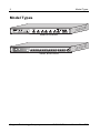
Model Types
Model Types
Model KNS800/R
Model KNS1600/R
Kingston Technology Company
KNS1600/R User’s Guide - Rev. B00
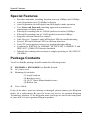
Special Features
3
Special Features
•
•
•
•
•
•
•
•
•
•
•
•
Provides automatic switching function between 10Mbps and 100Mbps
Auto-Negotiation for 10/100Mbps selection
Auto-Negotiation for half-duplex and full-duplex mode operation
Uses Store and Forward switching approach to minimize retransmission of faulty packets
Filtering/Forwarding rate of 148,800 packets/second at 100Mbps
Filtering/Forwarding rate of 14,880 packets/second at 10Mbps
Supports collision-based flow control
Link, Receive, Transmit, and Full Duplex LEDs for troubleshooting
Power LED and Collision LED for collision detection
Last UTP port supports crossover or straight-through cabling
Conforms to IEEE 802.3u 100BASE-TX, IEEE 802.3i 10BASE-T, and
IEEE 802.3 CSMA/CD Ethernet Standards
Internal auto-sensing universal power supply operating at 100-240VAC
(50/60Hz)
Package Contents
Your Fast EtheRx package should contain the following items:
‰
‰
‰
‰
KNS800/R or KNS1600/R Fast EtheRx Switch
AC power cord
Mounting kit includes:
(2) Angle brackets
(8) Bracket screws
(4) 10/32” Rack-Mount thumb screws
(4) Rubber feet
User's Guide
If any of the above items are missing or damaged, please contact your Kingston
dealer for a replacement. Be sure the items you receive are genuine Kingston
Technology products. If the Kingston name and logo are not on the front panel
of your unit, it is not a genuine Kingston product.
KNS1600/R User’s Guide - Rev. B00
Kingston Technology Company
4
Design Features
Compliance Standards
The Fast EtheRx Switch complies with the 10/100Mbps functions as defined by
IEEE802.3u 100BASE-TX, IEEE802.3i 10BASE-T, and IEEE802.3 CSMA/CD
Ethernet standards.
Design Features
Switching Function
The Fast EtheRx Switch is basically designed to bridge Standard 10BASE-T
Ethernet networks to 100BASE-TX Fast Ethernet networks and to segment 10Mbps
or 100Mbps network segments.
Auto-Negotiation
Auto-Negotiation provides the means of automatically establishing a link by
detecting the link capabilities of the connected device on the network to select the
best operational mode available (i.e. 10/100BASE-TX selection, half- / full-duplex
mode operation, etc.)
Full-Duplex
Full-Duplex transmission means that dedicated inbound and outbound channels are
established for bi-directional transmission of data. This allows the collision
detection mechanism (CSMA/CD) to be by-passed, thus decreasing transmission
delay normally caused by listening, collisions, and packet resends when operating in
half-duplex mode.
Store-and-Forward Switching
The Fast EtheRx Switch uses a packet-forwarding method called Store-andForward, which minimizes the re-transmission of faulty data packets. This means
that the Fast EtheRx Switch can store the incoming frame in an internal buffer and
check the packet for errors before sending it out to the destination port. If the frame
does contain errors, it will be discarded and then retransmitted.
Flow Control
The Fast EtheRx Switch implements a collision-based flow control mechanism that
reduces the risk of data being lost at the congested ports. This is accomplished by
forcing a collision with the data frames on all ports once the free-buffer queue has
reached the pre-set minimum.
Kingston Technology Company
KNS1600/R User’s Guide - Rev. B00
Hardware Installation
5
Hardware Installation
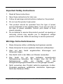
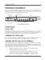
Before you begin installing network cables, please take a few moments to
familiarize yourself with Fast EtheRx Switch. The functions on the front and
rear panels are illustrated in the following sections.
100TX Speed
Detection LED
Power LED
Link / RX (Receive) LED
TX (Transmit) LED
Full-Duplex /
Collision LED
10/100BASE-TX
UTP Ports
Fig. 1-KNS800/R Front Panel
Front Panel
Power LED
The PWR LED indicates the power status of the Fast EtheRx switch. The LED
will light up steady green when the AC power cord is connected to the unit
from a power source and the power switch on the unit has been turned on.
100BASE-TX (100TX) LED
The 100TX LED will automatically light up when 100Mbps operation is
detected. This LED will not light up if 10Mbps operation is detected.
LINK/RX LED (for both 10 and 100Mbps)
The LINK/RX LED uses a single LED to display two functions. A steady
green light indicates that a good link has been established, and a flashing green
light indicates when data is being received. If the LED does not display solid
green indicating a good link, check the following:
1.
Make sure that the power is turned on for both the Fast
EtheRx Switch and the attached device.
2.
Verify that the drivers for the network adapter have been
loaded on the PC. Some network adapters require that the
driver be loaded before establishing a proper link.
KNS1600/R User’s Guide - Rev. B00
Kingston Technology Company
6
Front Panel
3.
Make sure the cable is wired properly and connected on both
ends.
4.
Make sure the correct cable type has been selected.
5.
If steps 1 through 4 are correct, please check the cable, as it
may be defective or wired incorrectly. Replace the cable and
try again. Please refer to Appendix A for Pin Assignments
and Appendix B for Cabling Guidelines.
TX LED (Model KNS800/R Only)
The TX LED displays a flashing green light when data is transmitted. A flash
may be longer or shorter depending on the length of the data packet being
transmitted.
Full Duplex and Collision LED
The FDX/COLL LED uses a dual color LED to display two functions. A solid
green light indicates that Full-Duplex operation has been detected. A flashing
amber light indicates that a collision has occurred in half-duplex mode. FullDuplex mode is auto-negotiated on all UTP ports.
UTP Ports
Depending on the model, the Fast EtheRx Switch has eight (8) or sixteen (16)
10/100Mbps UTP ports that auto-negotiate 10/100BASE-TX connections and
half- or full-duplex mode operation. The last UTP port has two RJ-45 port
connectors for support of UTP cabling in the crossover or straight-through
wiring configuration. Only one of the two ports may be utilized.
The RJ-45 port marked “MDI-X” is internally crossed like all other UTP ports.
By default, all repeater and switched UTP ports are generally configured as
standard MDI-X, or internally crossed ports. With a straight-through cable, this
port can be used for cascading to a standard MDI device, such as a network
adapter or router. With a crossover cable, this port can be used for cascading to
another MDI-X device, such as a hub.
The RJ-45 port marked “MDI” is a standard straight-through port. With a
crossover cable, this port can be used for cascading to another MDI device,
such as a network adapter or router. With a straight-through cable, this port can
be used for cascading to an internally crossed MDI-X device, such as a
repeater, or hub.
Kingston Technology Company
KNS1600/R User’s Guide - Rev. B00
Front Panel
7
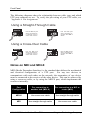
The following diagrams show the relationship between cable type and which
UTP port connector to use. To verify the pin wiring of your UTP cable, see
“Appendix A Pin Assignments.”
Using a Straight-Through Cable
PORT 8
MDI-X
MDI
PORT 8
Use the MDI-X port
when connecting to
a network card or
other MDI device.
MDI-X
MDI
Use the MDI port
when connecting to
a hub or other MDI-X
device.
Using a Cross-Over Cable
PORT 8
MDI-X
MDI
PORT 8
Use the MDI port
when connecting to
a network card or
other MDI device.
MDI-X
MDI
Use the MDI-X port
when connecting to
a hub or other MDI-X
device.
Notes on MDI and MDI-X
MDI (Media Dependent Interface) is the standard that defines the mechanical
and electrical configuration of a UTP port. For any two devices to
communicate with each other on the network, the transmitter of one device
must be connected to the receiver of the other device. This can be achieved by
using a crossover cable, or by using the MDI-X port, which implements the
crossover internally.
Port
Configuration
For connection to
another hub (MDI-X)
For connection to a NIC or
router (MDI)
MDI-X
Use cross-over cable
Use straight-through cable
MDI
Use straight-through cable
Use cross-over cable
KNS1600/R User’s Guide - Rev. B00
Kingston Technology Company
8
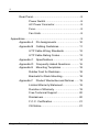
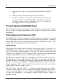
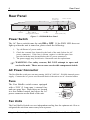
Rear Panel
Rear Panel
AC Power
Connector
Power Switch
U S E O N LY W I T H A 2 5 0 V F U S E
Fan Unit
MDI / MDI-X
C o n f i g u r a t i o n Ta b l e
Fan Unit
F u s e ( 2 5 0 V, 2 A )
Figure 2 – KNS800/R Rear Panel
Power Switch
The AC Power switch turns the unit kj or kbb. If the PWR LED does not
light up when the unit is turned on, please check the following:
1. Try a different AC power outlet.
2. Check the external fuse located in the back of the unit (below the AC
power connector.) If the fuse is blown, replace it with the spare fuse
provided with the unit (located below the AC power connector).
3. The power supply may be defective. Return the unit for replacement.
For safety reasons, DO NOT attempt to open and
) WARNING:
service the unit. There are no user-serviceable components inside.
AC Power Connector
The Fast EtheRx switch uses an auto-sensing 100VAC-240VAC, 50/60Hz internal power
supply. Connect the AC power cord from the back of the unit to an AC electrical outlet.
Fuse
The Fast EtheRx switch comes equipped
with a 250V (2 Amp max.) external fuse
and one spare fuse. Both fuses are located
in a fuse holder located just below the AC
power connector on the back of the unit.
U S E O N LY W I T H A 2 5 0 V F U S E
Fuse (250V, 2A)
USE
O N LY
WIT
250V
H A
FUS
E
Spare
Fuse
Fan Units
The Fast EtheRx Switch uses two independent cooling fans for optimum air- flow to
safeguard the unit from unnecessary heat exposure.
Kingston Technology Company
KNS1600/R User’s Guide - Rev. B00
Appendices
9
Appendices
KNS1600/R User’s Guide - Rev. B00
Kingston Technology Company
10
Appendix A Pin Assignments
Appendix A
Pin Assignments
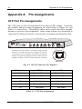
UTP Port Pin Assignments
The UTP ports use RJ-45 Unshielded Twisted Pair (UTP) cabling. Connector
pin numbers and pin wiring assignments are listed below in Figure A-1 and
Table A-1, respectively. Twisted-Pair cables can be wired with either straightthrough or crossover pin assignments. Both wiring schemes are mentioned in
"Appendix B Cabling Guidelines" for reference in creating a twisted-pair cable.
The UTP port labeled MDI is a standard straight-through
UTP port. All other UTP ports are configured as MDI-X,
or internally crossed. By default, all repeating and switched
UTP ports are generally configured as MDI-X, unless otherwise
specified. See page 7 Notes on MDI and MDI-X for details.
1 2 3 4 5 6 7 8
MDI
UTP Port
Fig. A-1 RJ-45 Connector Pin Numbers
Pin Number
MDI-X
MDI
1
Receive Data +
Transmit Data +
2
Receive Data -
Transmit Data -
3
Transmit Data +
Receive Data +
4,5
Not Used
Not Used
6
Transmit Data -
Receive Data -
7,8
Not Used
Not Used
Table A-1 UTP Pin Assignments
Kingston Technology Company
KNS1600/R User’s Guide - Rev. B00
Appendix B Cabling Guidelines
Appendix B
11
Cabling Guidelines
UTP Cable Type
When installing network cables, the following table shows appropriate cabling
guidelines for 100BASE-TX Fast Ethernet architecture.
Cabling Components:
100BASE-TX
Trunk and Patch Cable
Type:
4-Pair 100Ω UTP CAT 5
(only 2 pairs used)
Modular Plug:
8-Pin RJ-45 CAT 5 only
Patch Panel:
8-Pin RJ-45 CAT 5 only
Table B-1 Network Cable Guidelines
(NOTE: All UTP cables come in both solid and stranded filament. Solid
filament cables are more rigid and usually intended for trunk cabling.
Stranded filament cables are more pliable and generally targeted for patch
cables. For proper termination, use the correct RJ-45 connector, as they
differ for each type of cable.)
UTP Cable Wiring
UTP cables are wired based on one of two standard pin configurations:
Straight-Through and Crossover. 100BASE-TX uses only Category-5 UTP
cables with four pairs of wire as illustrated below in Tables B-2 and B-3.
"Straight-Through"
Configuration
Pin Number
1 (TRX+)
2 (TRX-)
3 (RCV+)
6 (RCV-)
4, 5, 7, 8
Pin Number
1 (TRX+)
2 (TRX-)
3 (RCV+)
6 (RCV-)
Not Used
Table B-2. Straight-Through Wiring
KNS1600/R User’s Guide - Rev. B00
"Cross-Over”
Configuration
Pin Number
1 (TRX+)
2 (TRX-)
3 (RCV+)
6 (RCV-)
4, 5, 7, 8
Pin Number
3 (RCV+)
6 (RCV-)
1 (TRX+)
2 (TRX-)
Not Used
Table B-3. Cross-Over Wiring
Kingston Technology Company
12
Appendix B
Cabling Guidelines
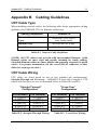
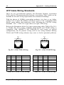
UTP Cable Wiring Standards
There are two governmental agencies: the Electronic Industry Association
(EIA) and the Telecommunications Industry Association (TIA), which set the
standard for all cable wiring requirements for commercial buildings.
With the advent of 100Mb/s networking products, it is best to use higher
quality CAT 5 cables like Belden or Helix as well as CAT 5-compliant patch
panels, patch cables, and connectors while following the EIA/TIA wiring
standards. 100 Ω UTP CAT 5 type cables use 4-pair UTP wiring.
Refer to the illustrations below for 4-pair wiring using either T568A (Fig. B-1)
or T568B (Fig. B-2) wiring standards. Both T568A and T568B wiring is
compatible with 10BASE-T and 100BASE-TX and require no special
configurations, but for premise wiring, stick to one wiring standard. Mixing
T568A and T568B wiring schemes may cause or lead to potential problems.
Pair 2
Pair 3
Pair 3 Pair 1 Pair 4
Pair 2 Pair 1 Pair 4
12345678
12345678
T568A
T568B
Fig. B-1 4-Pair T568A Wiring
Solid
Fig. B-2 4-Pair T568B Wiring
T568A
Pairs
Strand
Pin 1
Pair 3
Blue
White/Green
T568B
Pairs
Strand
Solid
Pin 1
Pair 2
Black
White/Orange
Pin 2
Pair 3
Orange
Green/White
Pin 3
Pair 2
Black
White/Orange
Pin 2
Pair 2
Yellow
Orange/White
Pin 3
Pair 3
Blue
White/Green
Pin 4
Pair 1
Red
Blue/White
Pin 4
Pin 5
Pair 1
Green
White/Blue
Pin 5
Pair 1
Red
Blue/White
Pair 1
Green
Pin 6
Pair 2
Yellow
Orange/White
White/Blue
Pin 6
Pair 3
Orange
Green/White
Pin 7
Pair 4
Brown
Pin 8
Pair 4
White
White/Brown
Pin 7
Pair 4
Brown
White/Brown
Brown/White
Pin 8
Pair 4
White
Brown/White
Table. B-4 4-Pair T568A Wiring
Kingston Technology Company
Table B-5 4-Pair T568B Wiring
KNS1600/R User’s Guide - Rev. B00
Appendix B
Cabling Guidelines
13
UTP Cable Rating Codes
UTP cables meet different UL-NEC requirements based mostly on cable-jacket
quality. Below is an explanation of the rating codes for each cable type.
UL – The National Electrical Code (NEC), published by the National Fire
Protection Association (NFPA), details advisory safety considerations for
electrical wiring. NEC Article 800 Communications Cables are manufactured
to meet these different cable types.
1.
CMP – Cables meeting type CMP requirements are suitable for
installation in ducts and plenums without the use of conduit. These cables
are designed for fire resistance and low-smoke and toxin producing
characteristics.
2.
CMR – Riser type cables are engineered to prevent the spread of fire from
floor to floor and are suitable for vertical shaft applications.
3.
CM – Cables for general building wiring. CM cables are used in areas
other than plenums and risers. These cables are resistant to the spread of
fire and pass the UL 1581Vertical Tray Flame Test.
4.
MP, MPR & MPP – Within Article 800, the Multi-purpose Cables
Category, allows conditional substitutions between different cable types &
are restricted by number, AWG size and stranding of the cable conductors.
Terms You Should Be Familiar With
1.
BACKBONE WIRING – The physical/electrical interconnections
between telecommunications wiring closets and equipment rooms.
2.
COMPLIANCE – A datacomm or wiring device that meets all
characteristics of a standard is said to be in compliance with that standard.
3.
PREMISE WIRING – The entire wiring system on the premises,
especially the supporting wiring that connects the communications outlets
to the network interface jack.
PJ
NEAR-END CROSSTALK (NEXT) – In wires packed together within a
cable, the signals generated at one end of the link can flush out the weaker
signals coming back from the recipient.
KNS1600/R User’s Guide - Rev. B00
Kingston Technology Company
14
Appendix C
Appendix C
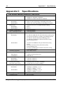
Specifications
Specifications
Fast EtheRx Models KNS800/R, KNS1600R
Compliance:
IEEE 802.3u 100BASE-TX Standard
IEEE802.3i 10BASE-T Standard
IEEE802.3 CSMA/CD Ethernet Standard
Media Interface:
KNS800/R
KNS1600/R
Eight (8) auto-negotiating 10/100 Mbps UTP ports
Sixteen (16) auto-negotiating 10/100 Mbps UTP ports
Uplink Port:
KNS800/R
KNS1600/R
Supports cross-over or straight-through cabling
Port 8
Port 16
10BasE-T/100BASE-TX
Auto-Negotiation
Half / Full-duplex mode:
Auto-Negotiation
Diagnostic LEDs:
1 LED for Power Indicator (green)
KNS800/R
8 LEDs for 100BASE-TX speed detection (steady green)
8 LEDs for Link/Receive (steady green/flashing green)
8 LEDs for Transmit detection (flashing green)
8 LEDs for Full-Duplex/Collision detection (steady
green/flashing amber)
KNS1600/R
16 LEDs for 100BASE-TX speed detection (steady
green)
16 LEDs for Link/Activity detection (steady
green/flashing green)
16 LEDs for Full Duplex/Collision detection (steady
green/flashing amber)
Switching Approach:
Store-and-Forward
Flow Control:
Half-Duplex
Full-Duplex:
Collision-based Backpressure
IEEE 802.3x
MAC Address Support:
KNS800/R
KNS1600/R
17K MAC addresses
12K MAC addresses
Filtering/Forwarding
Rate (min. packet size):
148,800 packets/second @ 100Mbps
14,880 packets/second @ 10Mbps
Latency (min. packet size.)
KNS800/R
KNS1600/R
100Mbps to 100Mbps ≤ 9.8µs
10Mbps to 10Mbps ≤ 68.5µs
100Mbps to 100Mbps ≤ 12.5µs
10Mbps to 10Mbps ≤ 69.7µs
Max Segment Length:
100 meters (328 feet)
Connector Type:
RJ-45, Female
Kingston Technology Company
KNS1600/R User’s Guide - Rev. B00
Appendix C
Specifications
15
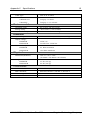
Cable Type:
UTP 26 to 22 AWG
Cable Grade:
100BASE-TX:
10BASE-T:
Category 5 or better
Category 3, 4, 5 or better
Environmental:
Operating Temp.
0°C to 45°C (32°F to 113°F)
Storage Temp.
-20°C to 60°C (-4°F to 140°F)
Relative Humidity
10% to 90% non-condensing
Electrical:
Input Voltage:
90VAC – 264VAC, 50/60Hz, Autosensing
Output Voltage:
KNS800/R
KNS1600/R
5VDC, 6A
3.3VDC/12A. 5VDC/4A
Power Consumption:
KNS800/R
KNS1600/R
9.3 Watts maximum
16.5 Watts maximum
Physical:
Dimension (HxWxD):
Weight:
KNS800/R
KNS1600/R
1.69” x 17.32” x 7.88”
(43.30mm x 443.40mm x 201.70mm)
5.7 lbs. (2.6 kg)
6.3 lbs. (2.9 kg)
Certification
EMI Standards:
FCC Class A, CE CISPR A
EMC Standards:
EN55022, IEC801-2, IEC801-3, IEC801-4
Low Voltage Directive:
EN60950
Safety Standards:
UL, cUL, TUV
KNS1600/R User’s Guide - Rev. B00
Kingston Technology Company
16
Appendix D
Appendix D
Frequently Asked Questions
Frequently Asked Questions
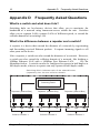
What is a switch and what does it do?
Switching hubs are low-latency devices that allow you to maximize the
bandwidth of a network using concurrent access within the unit. Switches
allow you to segment LANs, connect LANs of different speeds, or extend the
collision domain of an existing LAN.
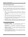
What’s the difference between a repeater and a switch?
A repeater is a device that extends the diameter of a network by regenerating
and forwarding received Ethernet packets. It repeats incoming signals to all
other ports on the device.
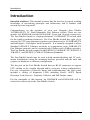
Like a repeater, a switch can also extend the diameter of a network. However,
a switch can also extend the collision domain of a network, like bridging a
10Mbps Ethernet LAN with a 100Mbps Fast Ethernet LAN.
See the
illustration below. A switch can also be configured to operate in half-duplex or
full-duplex mode, whereas a repeater can only operate in half-duplex mode.
Switching fabric isolates each of the shared buses
(repeaters) into its own collision domain.
Switching Fabric
Repeater (Shared Bus)
100
100
Repeater (Shared Bus)
100
Collision Domain 1
Kingston Technology Company
10
10
10
Collision Domain 2
Repeater (Shared Bus)
100
100
100
Collision Domain 3
KNS1600/R User’s Guide - Rev. B00
Appendix D
Frequently Asked Questions
17
Category 5 Compliance vs. Category 5 Performance?
Using CAT 5 cabling in your network installation does not necessarily achieve
full Category 5 performance. To achieve any category-rated performance, make
sure all cabling components, including modular plugs, trunk cables, and patch
panels, are at least of the minimum category required.
To achieve full CAT 5 performance, all components must be CAT 5 compliant
and terminated properly according to EIA/TIA-568 TSB-36 and TSB-40
guidelines.
What are the Guidelines for Proper Termination?
It is important to maintain the twists of the cable as close to the termination on
the outlet as possible, to avoid NEXT (Near End Cross Talk) and to maintain
the transmission characteristics of the Category. Category specifications require
that pair twisting, at the point of termination, not exceed the following
maximums:
•
Category 3 maximum allowed untwisting: 3 inches
•
Category 4 maximum allowed untwisting: 1 inch
•
Category 5 maximum allowed untwisting: 1/2 inch
Can I mix CAT 3 and CAT 5 cabling in the same building?
Yes, but keep in mind, you will not have CAT 5 performance. It is a good idea
to keep the lines separated, physically and by color, when installing any new
lines, use CAT 5 UTP cabling only.
Can a Four-Pair CAT 5 cable support two 100BASE-TX
devices?
Although only two pairs are used in the standard four-pair CAT 5 UTP cable, it
is not recommended because it exceeds the specifications outlined by IEEE
802.3u.
KNS1600/R User’s Guide - Rev. B00
Kingston Technology Company
18
Appendix E
Appendix E
Mounting Templates
Mounting Templates
The Fast EtheRx Switch can be stationed on a flat surface using the four rubber
feet provided, or mounted in a standard 19” rack by using the mounting
brackets and 4 thumb screws provided with the unit.
Rubber Feet for Desktops
The Fast EtheRx Switch comes with rubber feet that may be applied to the
bottom of the unit for desktop surface installations. The 4 rubber feet have peeloff adhesive backing. Remove the backing and attach the feet to the bottom of
the switch.
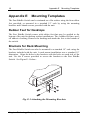
Brackets for Rack Mounting
The Fast EtheRx Switch can also be mounted in a standard 19” rack using the
brackets included with the unit. A rack mount installation uses a standard 19”
dimension. Align the holes in the brackets with the holes on each side of the
unit. Use the 8 screws provided to secure the brackets to the Fast EtheRx
Switch. See Figure E-1 below:
Fig. E-1-Attaching the Mounting Brackets
Kingston Technology Company
KNS1600/R User’s Guide - Rev. B00
Appendix F
Product Warranties and Notices
Appendix F
19
Product Warranties and Notices
Limited Warranty Statement
KINGSTON TECHNOLOGY COMPANY ("Kingston") warrants that this product is
free from defects in material and workmanship. Subject to the conditions and limitations
set forth below, Kingston will, at its option, either repair or replace any part of this
product which proves defective by reason of improper workmanship or materials. Repair
parts or replacement products will be provided by Kingston on an exchange basis, and
will either be new or refurbished to be functionally equivalent to new.
This warranty does not cover any damage to this product that results from accident,
abuse, misuse, natural or personal disaster, or any unauthorized disassembly, repair or
modification.
Duration of Warranty
Lifetime Warranty: The following Kingston products are covered by this warranty for life:
memory modules and expansion boards, networking adapters, networking hubs without cooling
fans (excluding the power supply), and microprocessor upgrade products.
Seven Year Warranty: The following Kingston products are covered by this warranty for a
period of seven years from the date of original retail purchase: all core storage enclosures
(including the power supply), cables, terminators, and related accessories. Under certain
agreements where core products are slightly modified (e.g. paint, handle, etc.) by Kingston at
the customer’s request, the product will be covered for a period of seven years for repair only.
Storage products that are custom designed and /or incorporate component-level modification by
Kingston in order to meet specific customer requests, will be negotiated with the applicable
customer on a per case basis.
Five Year Warranty: The following Kingston products are covered by this warranty for a
period of five years from the date of original retail purchase: the power supply in networking
hubs without cooling fans; Flash memory cards (e.g. CompactFlash, ATA Flash, and Linear
Flash); solid state PC Card (PCMCIA) adapters, PC Card Readers and all other Kingston
products (other than those products covered by a three-year, two-year, or one-year warranty, as
provided below).
Three Year Warranty: The following Kingston products are covered by this warranty for a
period of three years from the date of original retail purchase: networking hubs with cooling
fans (including the power supply).
Two Year Warranty: The following Kingston products are covered by this warranty for a
period of two years from the date of original retail purchase: Solid State Floppy Disk Cards
(SSFDC), and Winchester hard disk drives in a 2.5 inch, 3.5 inch or 5.25 inch form factor.
One Year Warranty: The following Kingston products are covered by this warranty for a
period of one year from the date of original retail purchase: Winchester hard disk drives in a
1.8 inch form factor, optical storage products, and magnetic tape storage products.
Rev. 3/99
KNS1600/R User’s Guide - Rev. B00
Kingston Technology Company
20
Appendix F
Product Warranties and Notices
Warranty Claim Requirements
To obtain warranty service, return the defective product, freight prepaid and insured, to
your local authorized Kingston dealer or distributor, or to the Kingston factory service
center located at 17600 Newhope Street, Fountain Valley, California 92708, U.S.A. You
must include the product serial number (if applicable) and a detailed description of the
problem you are experiencing. You must also include proof of the date of original retail
purchase as evidence that the product is within the applicable warranty period. If you
return the product directly to the Kingston factory, you must first obtain a Return
Material Authorization ("RMA") number by calling Kingston Customer Service at
(714) 438-1810, and include the RMA number prominently displayed on the outside of
your package. Products must be properly packaged to prevent damage in transit.
Free Technical Support
Kingston provides free technical support. If you experience any difficulty during
the installation or subsequent use of a Kingston product, please contact Kingston’s
Technical Support department prior to servicing your system.
Kingston Technical Support can be reached in the U.S. at (714) 435-2639 or tollfree at (800) 435-0640 (U.S. and Canada only). Kingston European Technical
Support can be reached from within the U.K. at 01932 738858. Kingston provides
other service numbers when calling from Germany 0130 115 639 or fax 0130 860
599, from Austria 0660 5569 or fax 06 607 434, from Switzerland 0800 557 748 or
fax 0800 552 182, from France 0800 905 701 or fax 0800 900 910, or from Belgium
(in English) 0800 72763.
This warranty covers only repair or replacement of defective Kingston products, as
provided above. Kingston is not liable for, and does not cover under warranty, any
costs associated with servicing and/or the installation of Kingston products.
Disclaimers
The foregoing is the complete warranty for Kingston products and supersedes all
other warranties and representations, whether oral or written. Except as expressly
set forth above, no other warranties are made with respect to Kingston products
and Kingston expressly disclaims all warranties not stated herein, including, to the
extent permitted by applicable law, any implied warranty of merchantability or
fitness for a particular purpose. In no event will Kingston be liable to the
purchaser, or to any user of the Kingston product, for any damages, expenses, lost
revenues, lost savings, lost profits, or any other incidental or consequential damages
arising from the purchase, use or inability to use the Kingston product, even if
Kingston has been advised of the possibility of such damages.
Rev. 3/99
Copyright © 1997-2000 Kingston Technology Company. All rights reserved. Printed in Taiwan. Kingston
Technology and the Kingston logo are trademarks of Kingston Technology Company. All other logos and trademarks
are properties of their respective companies.
Kingston Technology Company
KNS1600/R User’s Guide - Rev. B00
Appendix F
Product Warranties and Notices
21
F.C.C. Certification
This device has been tested and found to comply with limits for Class B digital device,
pursuant to Part 15 of the FCC Rules. Operation is subject to the following two
conditions:
(1)
(2)
This device may not cause harmful interference, and
This device must accept any interference received; including
interference that may cause undesired operation.
CE Notice
The official CE symbol indicates compliance of this Kingston Technology
product to the EMC directive of the European Community. The CE symbol
indicates that this Kingston product meets or exceeds the following standards:
‰
EN50081-1 “Electromagnetic Compatibility-generic emissions standard”
EN55022:
‰
“Limits and methods of measurement of radio
interference characteristics.”
EN50082-1 “Electromagnetic Compatibility-generic immunity standard”
IEC 801-2: “Electrostatic discharge requirements”
IEC 801-3: “Radiated immunity requirements”
IEC 801-4: “Electrical fast transient requirements”
‰
EN60950
‰
Declaration of CE Conformity in accordance with the above standards has been
made and is on file at Kingston Technology.
“Low Voltage Directive (LVD)”
KNS1600/R User’s Guide - Rev. B00
Kingston Technology Company