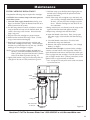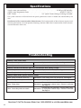
1
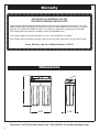
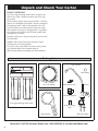
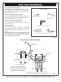
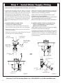
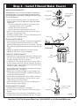
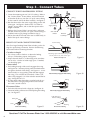
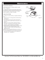
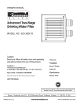
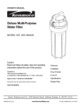
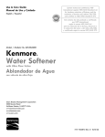
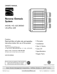
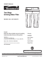
OWNER'S MANUAL
Two-Stage
Drinking Water Filter
MODEL NO. 625.384610
Caution:
Read and follow all safety rules and operating
instructions before first use of this product.
• Warranty
• Installation
Questions ?
Visit www.KenmoreWater.com
or call toll free 1-800-426-9345 (M - F, 7 AM - 8 PM CST)
• How It Works
Repair or Parts ? Call toll free 1-800-469-4663
• Specifications
See back cover for other Sears service numbers.
• Repair Parts
• Care Of
SAVE THIS MANUAL
System Tested and Certified by NSF International against
NSF/ANSI Standard 42. See performance data sheet for details.
Sears, Roebuck and Co., 3333 Beverly Road, Hoffman Estates, IL 60179 U.S.A.
PRINTED IN U.S.A.
www.KenmoreWater.com
Part No.7293858 (Rev. C 5/2/07)
Warranty
ONE YEAR FULL WARRANTY ON THE
TWO-STAGE DRINKING WATER FILTER
When installed, operated and maintained according to all instructions supplied with the product, if this TwoStage Drinking Water Filter fails due to a defect in material or workmanship within one year from the date of
purchase, call 1-800-4-MY-HOME to arrange for free repair (or replacement if repair proves impossible).
This warranty does not include filter cartridges, which are expendable items.
This warranty applies only while this product is in use in the United States or Canada.
This warranty gives you specific legal rights, and you may have other rights which vary from state to state.
Sears, Roebuck and Co., Hoffman Estates, IL 60179
Dimensions
13"
9-5/8"
4-5/8"
Questions? Call The Kenmore Water Line 1-800-426-9345 or visit KenmoreWater.com
2
Table of Contents
Unpack and Check Shipment . . . . . . . . . . . . . . . . . . . . . . . . . . . . . . . . . . . . . . . . . . . . . . . . . . . . . . . . . . . . . . . . . . . . . . . . . . . . .4
Plan Your Installation . . . . . . . . . . . . . . . . . . . . . . . . . . . . . . . . . . . . . . . . . . . . . . . . . . . . . . . . . . . . . . . . . . . . . . . . . . . . . . . . . . .5
Step 1-Install Supply Water Fitting . . . . . . . . . . . . . . . . . . . . . . . . . . . . . . . . . . . . . . . . . . . . . . . . . . . . . . . . . . . . . . . . . . . . . . . .6
Step 2-Install Filtered Water Faucet . . . . . . . . . . . . . . . . . . . . . . . . . . . . . . . . . . . . . . . . . . . . . . . . . . . . . . . . . . . . . . . . . . . . . . . .7
Step 3-Connect Tubes . . . . . . . . . . . . . . . . . . . . . . . . . . . . . . . . . . . . . . . . . . . . . . . . . . . . . . . . . . . . . . . . . . . . . . . . . . . . . . . . . . . .8
Maintenance . . . . . . . . . . . . . . . . . . . . . . . . . . . . . . . . . . . . . . . . . . . . . . . . . . . . . . . . . . . . . . . . . . . . . . . . . . . . . . . . . . . . . . . . .9-11
Specifications . . . . . . . . . . . . . . . . . . . . . . . . . . . . . . . . . . . . . . . . . . . . . . . . . . . . . . . . . . . . . . . . . . . . . . . . . . . . . . . . . . . . . . . . . .12
Troubleshooting . . . . . . . . . . . . . . . . . . . . . . . . . . . . . . . . . . . . . . . . . . . . . . . . . . . . . . . . . . . . . . . . . . . . . . . . . . . . . . . . . . . . . . .12
Exploded View & Parts List . . . . . . . . . . . . . . . . . . . . . . . . . . . . . . . . . . . . . . . . . . . . . . . . . . . . . . . . . . . . . . . . . . . . . . . . . .14-15
Safety Guides
Read all steps and guides carefully before installing
and using your Two-Stage Drinking Water Filter.
Follow all steps exactly to correctly install. Reading
this manual will also help you to get all the benefits
from the Two-Stage Drinking Water Filter.
The Two-Stage Drinking Water Filter works on water
pressures of 30 psi (minimum) to 100 psi (maximum).
If your house water pressure is over the maximum,
install a pressure reducing valve in the water supply
pipe to the Two-Stage Drinking Water Filter.
Do not attempt to use this product to make safe
drinking water from non-potable water sources. Do
not use the system on microbiologically unsafe water,
or water of unknown quality without adequate disinfection before or after the system.
Do not install the Two-Stage Drinking Water Filter
outside, or in extreme hot or cold temperatures.
Temperature of the water supply to the Two-Stage
Drinking Water Filter must be between 40°F and
100°F. Do not install on hot water.
Check with your local public works department for
plumbing and sanitation codes. You must follow
their guides as you install the system. Follow your
local codes if they differ with guides in this manual.
In Massachusetts, plumbing codes of Massachusetts
shall be adhered to. Consult with a licensed plumber.
Questions? Call The Kenmore Water Line 1-800-426-9345 or visit KenmoreWater.com
3
Unpack and Check Your Carton
INSPECT SHIPMENT
Your Two-Stage Drinking Water Filter is shipped complete in one carton. Remove all items from your shipping carton.
Check all items against the packing list below. Note any
items lost or damaged in shipment. Note any damage to
the shipping carton. Refer to the exploded view and
parts list in the back of the manual for the part names
and numbers of missing or damaged items. If problems
exist, refer to the website or the toll free number listed
throughout this manual.
Keep the small parts in the parts bag until you are ready
to install them.
NOTE: Codes in the state of Massachusetts require
installation by a licensed plumber.
If you live in the state of Massachusetts, review plumbing code 248-CMR of the Commonwealth of
Massachusetts before proceeding with the installation.
Packing List
Bag Assembly
Coin Battery
3/8” O.D. Tubing
Mounting Screws
Faucet
Tee Feed Adaptor
Two-Stage Drinking Water Filter
Thread Sealing
Tape
Sump Wrench
Electronics Base
Questions? Call The Kenmore Water Line 1-800-426-9345 or visit KenmoreWater.com
4
Plan Your Installation
PLAN YOUR INSTALLATION
It is recommended to read through the entire manual
before beginning your installation. Follow all steps
exactly. Reading this manual will also help you get all
the benefits from your system.
Tools Needed
TYPICAL UNDER SINK LOCATION
The Two-Stage Drinking Water Filter housing is normally located under the kitchen and/or bathroom sink, to filter the cold drinking water. See Figure 2.
Phillips Screwdriver
Adjustable Wrench
CHECK SPACE REQUIREMENTS
Check size and position of items for proper installation
into location chosen.
TOOLS NEEDED
Drill & 1-1/4” bit, if required
Review the tools needed list. See Figure 1. Gather needed tools before proceeding with the installation. Read
and follow the instructions provided with any tools listed here.
IMPORTANT: A 1-1/4” dia. hole is needed to mount the
filtered water faucet. To avoid damaging the sink, consult a qualified plumber or installer for drilling procedures in porcelain or stainless steel.
Large Adjustable Jaw Pliers or Pipe Wrench
Figure 1
Typical Under Sink Installation
filtered water
faucet
7-5/8"
SINK
cold water
supply fitting
tubing
mounting
screws (2)
WATER
IN
WATER
OUT
Filter I
Filter II
cold water shutoff
NOTE: To change the filter cartridge,
turn off the water and release pressure
by opening the faucet. A nearby shutoff
is convenient. Most sinks already have
shutoff valves on the supply pipes.
NOTE: Allow a minimum space of 1-1/2” under the
system for removing the sumps (to change cartridges).
Figure 2
Questions? Call The Kenmore Water Line 1-800-426-9345 or visit KenmoreWater.com
5
Step 1 - Install Water Supply Fitting
CHOOSE TYPE OF WATER SUPPLY FITTING TO INSTALL
Locate the cold water line in the sink cabinet. Check and
comply with local plumbing codes as you plan, and then
install a water supply fitting on the sink’s cold water line.
The fitting must provide a leak-tight connection to the
Two-Stage Drinking Water Filter’s 3/8” O.D. inlet tubing.
A typical connection using the included water supply fitting is shown in Fig. 3. An alternative connection using
standard plumbing fittings (not included) is shown in
Fig. 4.
NOTE: Local code may dictate which type of water fitting is used. Consult a plumber if you are not familiar
with local codes or plumbing procedures.
A. WATER SUPPLY CONNECTION
USING INCLUDED FITTING
B. WATER SUPPLY TYPICAL CONNECTION
USING COMPRESSION TYPE FITTING
(PARTS NOT INCLUDED)
1. Close the house main water shutoff valve and open
faucets to drain water from the sink’s cold water pipe.
NOTE: Before starting, be sure to turn off water supply
and open a low faucet to drain the pipe.
2. Remove the nut that connects the cold water faucet to
cold water plumbing.
3. Thread the included water supply fitting onto the pipe
and reconnect nut to bottom of fitting.
cold water
faucet stud
NOTE: Codes in the state of Massachusetts require
installation by a licensed plumber.
If you live in the state of Massachusetts, review plumbing code 248-CMR of the Commonwealth of
Massachusetts before proceeding with the installation.
Complying with plumbing codes, install a fitting on the
cold water pipe to adapt to 3/8” O.D. tubing. A typical
connection is shown in Figure 4 If threaded fittings are
used, be sure to use pipe joint compound or Teflon tape
on outside threads.
included water
supply fitting
3/8” O.D. yellow
tubing to Water
Filter inlet
wrap outside
threads with
Teflon tape
cold water
pipe
OR
cold water
shutoff valve
3/8” compression
fitting
insert
ferrule
cold water
pipe
cold water
shutoff valve
Figure 3
3/8” yellow
tubing to
Water Filter inlet
Figure 4
Questions? Call The Kenmore Water Line 1-800-426-9345 or visit KenmoreWater.com
6
Step 2 - Install Filtered Water Faucet
MAKE HOLE FOR FAUCET
IMPORTANT: A 1-1/4” dia. hole is needed to mount the filtered water faucet. To avoid damaging the sink, consult a
qualified plumber or installer for drilling procedures in porcelain or stainless steel.
1. Select one of the following options to install the faucet.
Make sure there is room underneath to make the needed
connections.
Use an existing sink top hole for spray hose or soap
dispenser (must be 1-1/4” in diameter).
Drill a new hole in the sink top.
Drill a hole in the countertop next to the sink.
2. Check to make sure the filtered water faucet base will sit
flat against the mounting surface.
3. If drilling is needed, make a 1-1/4” dia. (minimum) hole for
the faucet in the mounting surface.
faucet base
1-1/4” dia. hole
through sink or
countertop
rubber gasket
toggle bolts
Figure 5
faucet
faucet base
INSTALL FAUCET BASE
1. Locate the faucet base (See Fig. 5) and feed the toggle bolts
down through the hole until the faucet base is square
against the mounting surface (sink or countertop). The rubber gasket should be between the faucet base and mounting
surface.
2. Tighten the toggle bolts until the faucet base is firmly
mounted to the surface. Do not overtighten.
CONNECT TUBE TO FAUCET
1. Mount the Two-Stage Drinking Water Filter assembly under
the sink. Allow a minimum of 1-1/2” under the sumps for
changing cartridges (See Fig. 2 on Page 5).
2. Locate the 3/8” O.D. tubing. Refer to the “Connect Tubes”
section on Page 8 and insert one end of the tube all the way
into the 3/8” quick connect fitting on the water OUT side of
the filter assembly. See Figure 6.
3. Feed the other end of the tubing up through the mounting
hole and faucet base. See Figure 6.
4. Refer to the “Cut Tubes to Length” section on Page 8 and
cut the tube square and to length as needed, leaving about
6 inches above the faucet base.
5. Locate the faucet. Refer to the “Connect Tubes” section on
Page 8 and insert the tube all the way into the 3/8” quick
connect fitting on the faucet bottom.
6. Pull on the tube at each end to be sure it is held firmly in
both of the quick connect fittings.
tubing
water
OUT
filter
assembly
Figure 6
faucet
INSTALL FAUCET ON BASE
1. Lower the faucet onto the base. See Figure 7.
2. Give the faucet a 1/4 turn clockwise to attach the faucet to
the base.
3. Install battery in faucet base (See “Change Battery” section
on Page 9) then continue installation with Step 3 on Page 8.
1/4 turn to connect
faucet to base
faucet base
Figure 7
Questions? Call The Kenmore Water Line 1-800-426-9345 or visit KenmoreWater.com
7
Step 3 - Connect Tubes
CONNECT TUBE TO WATER SUPPLY FITTING
1. Locate the remaining piece of 3/8” O.D. tubing. Refer to
the “Connect Tubes” section, below, and insert one end
of the tube all the way into the 3/8” quick connect fitting
on the water IN side of the filter assembly. See Figure 8.
2. Run the other end to the water supply fitting on the cold
water pipe. See Figure 8. Refer to the “Cut Tubes to
Length” section, below, and cut the tube square and to
length as needed.
3. Refer to the “Connect Tubes” section, below, and insert
the tube all the way into the 3/8” quick connect fitting on
included water supply fitting (installed in Step 1).
4. Pull on the tube at each end to be sure it is held firmly in
both of the quick connect fittings.
tubing
SINK
cold water
supply fitting
water
IN
cold water
shutoff
filtration
assembly
Figure 8
HOW TO CUT AND CONNECT THE TUBES
Your Two-Stage Drinking Water Filter includes push-in fittings for quick tubing connection. Review the following
instructions before connecting the tubes.
Push In Fitting
Tube
Cut tubes to length
1. Use a sharp cutter or knife to cut the end of tubing.
Always cut the tubing square. See Figure 9.
2. Inspect the end (about 1") of the tubing to be sure there
are no nicks, scratches or other rough spots. If needed,
cut the tubing again.
Cut tubing square with end of tubing round,
smooth, with no cuts, nicks or flat spots.
Tube Correctly Cut
Collet
Connect tubes
1. Push tubing through collet, until it engages the o-ring.
See Figure 10. Continue pushing until the tube bottoms
out against the back of the fitting. See Figure 11. A common mistake is to stop pushing when the tube engages
the o-ring. This will lead to future leaks. When a 3/8”
tube is fully engaged, 3/4” of the tube has entered the fitting. See Figures 10 & 11.
2. If using tubing other than tubing supplied with the system, be sure it is of high quality, exact size and roundness with a smooth surface.
O-Ring
Tube Partially Engaged With Fitting
Collet
Figure 9
Figure 10
O-Ring
Disconnect Tubes
1. Push the collet inward with a finger tip. See Figure 12.
2. Continue holding collet inward while pulling the tubing
out. See Figure 13.
Figure 11
Collet (Depress to
Remove Tubing)
O-Ring Seal
Collet
Tube Fully Engaged With Fitting
Fitting
Collet and O-Ring
Tubing
Figure 13
Disconnect Tubing
Figure 12
Questions? Call The Kenmore Water Line 1-800-426-9345 or visit KenmoreWater.com
8
Maintenance
FAUCET ELECTRONICS
Inside the faucet base is a battery operated 6 month
timer. See Figure 14.
An amber LED indicator is also located in the front of
the faucet base. This LED will flash continuously after 6
months has passed. This indicates that it is time to
replace the battery and filter carrtridges.
CHANGE BATTERY
To change (or install) the battery, complete the following
steps.
1. Loosen the screw on the right side of the faucet base
See Figure 14.
2. Press the battery housing upwards from the front
faucet base until it releases from the faucet base. See
Figure 14.
3. Replace (or install) the battery (Maxell CR 2032 or
equivalent). Place battery into the holder with the
positive (+) side facing the back of the holder.
4. When the battery is first replaced it will flash six times
and turn off. This indicates the battery is fully
charged. After the six flashes, the timer enters the 6
month time cycle.
NOTE: If the LED repeatedly flashes just two times, it is
not a fully charged battery and will need to be replaced.
5. Re-install the timer housing and firmly tighten the
mounting screw. See Figure 14.
battery
housing
battery,
negative (-)
side facing
the front
faucet
base
screw
Figure 14
Questions? Call The Kenmore Water Line 1-800-426-9345 or visit KenmoreWater.com
9
Maintenance
FILTER CARTRIDGE LIFE
OPTIONAL CARTRIDGES
It is recommended to replace the battery and filter cartridges every 6 months of use. There are several variables that determine how long a cartridge will last.
These include:
Other filter cartridges are available from Sears to reduce
sediments, tastes and odors, and chemical contaminants.
Following is a list of filter cartridges available:
1. How much water you use, and
2. How much sediment, taste and/or odor, or other
unwanted substances, are in the water.
Use the following information as a guide. However no
matter which type of cartridge you are using, you will
know it is time to replace it when you first notice the
return of unwanted substances in your water.
Kenmore Two-Stage Drinking Water Filter model
625.384610 with replacement cartridges 42-38480
(Sediment, 5 Micron)* and 42-34373 (Taste & Odor,
Premium) has been tested and certified by NSF international for the reduction of chlorine taste and odor. The
rated capacity for this system is 4,500 gallons (17,034
liters) at a rated service flow of 0.6 gpm (gallons per
minute).
Sediment Filter Cartridge, 25 Micron*: Sediment cartridges reduce sand, silt, clay, dirt and other sediments
from water. Sears Item No. 42-38478 filters the larger
sediments from water, and allows higher flows at less
pressure drop.
Taste and Odor Cartridges: Many bad tastes and/or
odors are reduced from water by an activated carbon
cartridge. It is most often used to reduce chlorine taste
and smell, usually to a single faucet such as the kitchen
cold.
NOTE: Small amounts of hydrogen sulfide (noticeable as
“rotten egg” odor) may be reduced by taste and odor filters for a short time, quickly exhausting the carbon
media. Consult your Sears store for proper continuous
treatment.
Sears Item No. 42-34370**: For reduction of chlorine
taste and odor.
Sears Item No. 42-34365*: For 99% chlorine reduction,
plus reduction of chemical contaminants.
Sears Item No.42-34377**: For reduction of lead, cysts,
and chlorine taste and odor.
* These cartridges have not been performance tested and certified by NSF International.
** These cartridges have been performance tested and certified
by NSF International in Model 625.384600.
Questions? Call The Kenmore Water Line 1-800-426-9345 or visit KenmoreWater.com
10
Maintenance
FILTER CARTRIDGE REPLACEMENT
Complete the following steps to replace the cartridges:
CAUTION: Never remove sumps with water pressure
in the filter system.
1. Close the water supply shutoff valve (See Fig. 2 on
Page 5) to the filter. Open the filtered water faucet to
relieve pressure in the system.
2. Use the sump removal wrench, included, to turn the
sump to the left to loosen it from the filter head. Be
careful - the sump is full of water. Do not lose the
large o-ring seal.
3. Dispose of the old cartridge in a proper manner.
4. Make sure the inside of the sump is clean. Use hot,
soapy water and rinse thoroughly.
5. Remove the wrapper from the new cartridge and
insert filter cartridge into the sump. Some cartridges
fit either way, while others fit only one way. Observe
markings on the cartridge or wrapper.
NOTE: If you are using filter numbers 42-38480 and
42-34373, place filter 42-38480 (Sediment*) in the
Filter I position and place filter 42-34373 (Taste &
Odor) in the Filter II position (See Fig. 15).
6. Lightly lubricate the o-ring seal in the sump with silicone grease. Be sure it is fully seated in its groove.
7. Hold the sump up to the filter head, aligning the center hole in the cartridge with the protrusion on the
bottom of the head.
NOTE: If the sump will not tighten up to the head, and
you are using cartridges other than 42-38480 and
42-34373, you may have the cartridge in upside
down. Take the cartridge out and check for correct orientation.
8. Being careful not to cross-thread, turn the sump to the
right onto the filter head and tighten securely.
9. Repeat steps 2 through 8 for the other filter.
10. Open the filtered water faucet. Then, slowly open
the water supply valve and allow the filter housing
to fill.
11. Close the filtered water faucet. Check for leaks
between the sumps and the heads.
12. Remove and replace the timer battery. See “Change
Battery” on Page 9.
Taste and Odor Cartridges: A taste and odor cartridge
contains activated carbon, a black powder. When new,
open the filtered water faucet and allow fine carbon particles to purge from the cartridge. Close the faucet when
you no longer see the “fines” (carbon particulates) in the
filtered water, or approximately 10 minutes.
* This cartridge has not been performance tested and certified
by NSF International.
Head
O-ring Seal
Filter
Cartridge
Sump
Filter II
Turn to the left
to remove
Filter I
Figure 15
Questions? Call The Kenmore Water Line 1-800-426-9345 or visit KenmoreWater.com
11
Specifications
Supply water pressure limits . . . . . . . . . . . . . . . . . . . . . . . . . . . . . . . . . . . . . . . . .30-100 psi (207-689 kPa)
Supply water temperature limits . . . . . . . . . . . . . . . . . . . . . . . . . . . . . . . . . . . . . . . . . . .40-100 °F (5-40 °C)
Inlet - Outlet . . . . . . . . . . . . . . . . . . . . . . . . . . . . . . . . . . .3/8” Quick Connect fittings & tubing, included
This system conforms to NSF/ANSI 42 for the specific performance claims as verified and substantiated by test
data.
Installations In The Commonwealth Of Massachusetts: The Commonwealth of Massachusetts requires installation be performed by a licensed plumber. Plumbing code 248--CMR of the Commonwealth of Massachusetts
must be followed in these cases.
Troubleshooting
Problem: Taste and/or Odor.
Cause: Filter cartridges expended.
Correction: Replace the filter cartridges. See Pages 10 & 11.
Cause: System contaminated.
Correction: Sanitize system. Call 1-800-426-9345 for instructions.
Problem: Faucet LED indicator light does not function after battery change.
Cause: Battery dead.
Correction: Replace with new battery. See Page 9.
Cause: Battery installed incorrectly..
Correction: Install battery correctly.
Problem: Water leaks at push connect fittings.
Cause: Tubing not pushed in all the way.
Correction: Push Tubing all the way into fittings. See Page 8.
Cause: Tubing not cut square.
Correction: Cut tubing square. See Page 8.
Cause: Tubing nicked.
Remove tube from connection. Remove nicked portion
Correction: by cutting tube to shorter length. Reinsert in connection
See Page 8.
Cause: Outer tubing surface not smooth.
Remove tube from connection. Remove problem area
Correction: by cutting tube to shorter length. Reinsert in connection
See Page 8.
Questions? Call The Kenmore Water Line 1-800-426-9345 or visit KenmoreWater.com
12
Notes
Questions? Call The Kenmore Water Line 1-800-426-9345 or visit KenmoreWater.com
13
Exploded View
3
1
2
6
4
5
5
6
7
8
9
14
13
10
Manifold Housing
PUSH-IN FITTINGS
11
collet
12
o-ring
seal
Questions? Call The Kenmore Water Line 1-800-426-9345 or visit KenmoreWater.com
14
Repair Parts List
Key No.
Part No.
Description
1
7292674
Faucet, with base & electronics
2
7293793
Mounting Bracket
3
7160453
Screw, #10-12 x 3/4” (8 req.)
4
9006053
Screw, #10-16 AB (2 req.)
5
7256864
Head (2 req.)
6
7168435
Tubing, 3/8” O.D. x 72” long, White
7
7279040
Tube, 3/8” O.D. x 1.78” long, White
8
7170246
O-ring, 3-3/8” I.D. x 3-5/8” O.D. (2 req.)
9
7205596
Sump (2 req.)
10
7228536
Tee Feed Adaptor
11
7193066
Wrench, Sump Removal
12
7209574
Push-in Fitting Kit, 3/8” 7154818
Coin Battery
7293858
Owner’s Manual
13
42-38480
Sediment Cartridge, 5 micron 14
42-34373
Taste & Odor Cartridge, Premium
42-38478
Sediment Cartridge, 25 micron 42-34370
Taste & Odor Cartridge 42-34365
Taste & Odor / Chemical Contaminant Cartridge 42-34377
Taste & Odor / Lead Cartridge O-ring and collet kit for replacement in the head only. Not included.
Not illustrated.
Optional replacement cartridges available at your local Sears store, online at
www.sears.com or from Sears Parts at 1-800-469-4663. Not included.
These cartridges have not been performance tested and certified by NSF
International.
These cartridges have been performance tested and certified by NSF International
in Model 625.384600.
Questions? Call The Kenmore Water Line 1-800-426-9345 or visit KenmoreWater.com
15
Get it fixed, at your home or ours!
Your Home
For repair – in your home – of all major brand appliances,
lawn and garden equipment, or heating and cooling systems,
no matter who made it, no matter who sold it!
For the replacement parts, accessories and
owner’s manuals that you need to do-it-yourself.
For Sears professional installation of home appliances
and items like garage door openers and water heaters.
1-800-4-MY-HOME®
(1-800-469-4663)
Call anytime, day or night (U.S.A. and Canada)
www.sears.com
www.sears.ca
For expert home solutions advice: www.managemyhome.com
Our Home
For repair of carry-in items like vacuums, lawn equipment,
and electronics, call or go on-line for the location of your nearest
Sears Parts & Repair Service Center
1-800-488-1222 (U.S.A.)
1-800-469-4663 (Canada)
Call anytime, day or night
www.sears.com
www.sears.ca
To purchase a protection agreement on a product serviced by Sears:
1-800-827-6655 (U.S.A.)
1-800-361-6665 (Canada)
Para pedir servicio de reparación
a domicilio, y para ordenar piezas:
Au Canada pour service en français:
1-888-SU-HOGAR
®
(1-888-784-6427)
® Registered Trademark /
® Marca Registrada /
MC
TM
TM
Trademark /
SM
Marca de Fábrica /
Marque de commerce /
MD
1-800-LE-FOYERMC
(1-800-533-6937)
www.sears.ca
Service Mark of Sears Brands, LLC
SM
Marca de Servicio de Sears Brands, LLC
Marque de déposée de Sears Brands, LLC
© Sears Brands, LLC