1
User's Manual
PK80 Series
80-Column Printer
Intermec Technologies Corporation
Corporate Headquarters
6001 36th Ave. W.
Technical Communications Department
550 Second Street SE
Everett, WA 98203
U.S.A.
Cedar Rapids, IA 52401
U.S.A.
www.intermec.com
The information contained herein is proprietary and is provided solely for the purpose of allowing customers
to operate and service Intermec-manufactured equipment and is not to be released, reproduced, or used for
any other purpose without written permission of Intermec.
Information and specifications contained in this document are subject to change without prior notice and do
not represent a commitment on the part of Intermec Technologies Corporation.
E 2003-2005 by Intermec Technologies Corporation. All rights reserved.
The word Intermec, the Intermec logo, Norand, ArciTech, CrossBar, Data Collection Browser, dcBrowser,
Duratherm, EasyCoder, EasyLAN, Enterprise Wireless LAN, EZBuilder, Fingerprint, i-gistics, INCA (under
license), InterDriver, Intermec Printer Network Manager, IRL, JANUS, LabelShop, Mobile Framework,
MobileLAN, Nor*Ware, Pen*Key, Precision Print, PrintSet, RoutePower, TE 2000, Trakker Antares, UAP,
Universal Access Point, and Virtual Wedge are either trademarks or registered trademarks of Intermec
Technologies Corporation.
Throughout this manual, trademarked names may be used. Rather than put a trademark (™ or ®) symbol in
every occurrence of a trademarked name, we state that we are using the names only in an editorial fashion,
and to the benefit of the trademark owner, with no intention of infringement.
There are U.S. and foreign patents pending.
Bluetooth is a trademark of Bluetooth SIG, Inc., U.S.A.
ii
PK80 Series 80-Column Printer User’s Manual
Document Change Record
This page records changes to this document. The document was originally released as Revision A.
Revision
Date
Description of Change
B
05/2003
Updated information about Bluetooth configuration
C
10/2003
Added Easy Print commands, default and downloable fonts.
D
04/2004
Added printer behavior information to Chapter 2, “Operations.” Added additional downloadable fonts to Appendix B, “Fonts.” Updated printer paper specifications in Chapter 1,
“Introduction.” Added Appendix C, “Graphics Printing.”
E
12/2004
Added additional setting page length commands to Appendix C, “Graphics Printing.”
F
02/2005
Updated Chapter 4, “Troubleshooting,” to include the latest self-test information.
PK80 Series 80-Column Printer User’s Manual
iii
iv
PK80 Series 80-Column Printer User’s Manual
Contents
Contents
Before You Begin . . . . . . . . . . . . . . . . . . . . . . . . . . . . . . . . . . . . . . . . . . . . . . . . . . . . . . . . . . . . . . ix
Safety Summary . . . . . . . . . . . . . . . . . . . . . . . . . . . . . . . . . . . . . . . . . . . . . . . . . . . . . . . . ix
Do not repair or adjust alone . . . . . . . . . . . . . . . . . . . . . . . . . . . . . . . . . . . . . . . . ix
First aid . . . . . . . . . . . . . . . . . . . . . . . . . . . . . . . . . . . . . . . . . . . . . . . . . . . . . . . . ix
Resuscitation . . . . . . . . . . . . . . . . . . . . . . . . . . . . . . . . . . . . . . . . . . . . . . . . . . . . ix
Energized equipment . . . . . . . . . . . . . . . . . . . . . . . . . . . . . . . . . . . . . . . . . . . . . . ix
Safety Icons . . . . . . . . . . . . . . . . . . . . . . . . . . . . . . . . . . . . . . . . . . . . . . . . . . . . . . . . . . . . x
Global Services and Support . . . . . . . . . . . . . . . . . . . . . . . . . . . . . . . . . . . . . . . . . . . . . . . xi
Warranty Information . . . . . . . . . . . . . . . . . . . . . . . . . . . . . . . . . . . . . . . . . . . . . xi
Web Support . . . . . . . . . . . . . . . . . . . . . . . . . . . . . . . . . . . . . . . . . . . . . . . . . . . . xi
Telephone Support . . . . . . . . . . . . . . . . . . . . . . . . . . . . . . . . . . . . . . . . . . . . . . . . xi
Who Should Read this Manual? . . . . . . . . . . . . . . . . . . . . . . . . . . . . . . . . . . . . . . . . . . . xii
Related Documents . . . . . . . . . . . . . . . . . . . . . . . . . . . . . . . . . . . . . . . . . . . . . . . . . . . . . xii
1
Introduction
............................................................... 1
About the Printer . . . . . . . . . . . . . . . . . . . . . . . . . . . . . . . . . . . . . . . . . . . . . . . . . . . . . . . . . . . . . .
Cables . . . . . . . . . . . . . . . . . . . . . . . . . . . . . . . . . . . . . . . . . . . . . . . . . . . . . . . . . . . . . . . .
Hinges on Printer Cover . . . . . . . . . . . . . . . . . . . . . . . . . . . . . . . . . . . . . . . . . . . . . . . . . .
Paper . . . . . . . . . . . . . . . . . . . . . . . . . . . . . . . . . . . . . . . . . . . . . . . . . . . . . . . . . . . . . . . . .
Material Breakdown . . . . . . . . . . . . . . . . . . . . . . . . . . . . . . . . . . . . . . . . . . . . . . .
Caliper Breakdown . . . . . . . . . . . . . . . . . . . . . . . . . . . . . . . . . . . . . . . . . . . . . . . .
Printer Dimensions . . . . . . . . . . . . . . . . . . . . . . . . . . . . . . . . . . . . . . . . . . . . . . . . . . . . . .
Remote Connections . . . . . . . . . . . . . . . . . . . . . . . . . . . . . . . . . . . . . . . . . . . . . . . . . . . . .
User Panel . . . . . . . . . . . . . . . . . . . . . . . . . . . . . . . . . . . . . . . . . . . . . . . . . . . . . . . . . . . . .
Forward and Reverse Buttons . . . . . . . . . . . . . . . . . . . . . . . . . . . . . . . . . . . . . . . .
Radio Button . . . . . . . . . . . . . . . . . . . . . . . . . . . . . . . . . . . . . . . . . . . . . . . . . . . .
Vehicle Battery . . . . . . . . . . . . . . . . . . . . . . . . . . . . . . . . . . . . . . . . . . . . . . . . . . . . . . . . .
2
3
3
4
4
5
5
6
6
6
7
7
Specifications . . . . . . . . . . . . . . . . . . . . . . . . . . . . . . . . . . . . . . . . . . . . . . . . . . . . . . . . . . . . . . . . . 8
Inside Sales . . . . . . . . . . . . . . . . . . . . . . . . . . . . . . . . . . . . . . . . . . . . . . . . . . . . . . . . . . . . . . . . . . . 9
What’s New . . . . . . . . . . . . . . . . . . . . . . . . . . . . . . . . . . . . . . . . . . . . . . . . . . . . . . . . . . . . . . . . . 10
2
Operation
. . . . . . . . . . . . . . . . . . . . . . . . . . . . . . . . . . . . . . . . . . . . . . . . . . . . . . . . . . . . . . . . . 11
Check List . . . . . . . . . . . . . . . . . . . . . . . . . . . . . . . . . . . . . . . . . . . . . . . . . . . . . . . . . . . . . . . . . . 12
Open the Printer . . . . . . . . . . . . . . . . . . . . . . . . . . . . . . . . . . . . . . . . . . . . . . . . . . . . . . . . . . . . . 12
Install the Ribbon Cartridge . . . . . . . . . . . . . . . . . . . . . . . . . . . . . . . . . . . . . . . . . . . . . . . . . . . . . 13
Adjust the Print Head Gap . . . . . . . . . . . . . . . . . . . . . . . . . . . . . . . . . . . . . . . . . . . . . . . . . . . . . 14
PK80 Series 80-Column Printer User’s Manual
v
Contents
Fill the Paper Tray . . . . . . . . . . . . . . . . . . . . . . . . . . . . . . . . . . . . . . . . . . . . . . . . . . . . . . . . . . . . 15
Fill the Compact Paper Tray . . . . . . . . . . . . . . . . . . . . . . . . . . . . . . . . . . . . . . . . . . . . . . 15
Fill the Dashboard Mount Paper Tray . . . . . . . . . . . . . . . . . . . . . . . . . . . . . . . . . . . . . . 17
3
Load Paper into Printer . . . . . . . . . . . . . . . . . . . . . . . . . . . . . . . . . . . . . . . . . . . . . . . . . . . . . . . .
Position the Paper . . . . . . . . . . . . . . . . . . . . . . . . . . . . . . . . . . . . . . . . . . . . . . . . . . . . . .
Adjust the Pinfeed Holders . . . . . . . . . . . . . . . . . . . . . . . . . . . . . . . . . . . . . . . . . . . . . . .
Set the Paper . . . . . . . . . . . . . . . . . . . . . . . . . . . . . . . . . . . . . . . . . . . . . . . . . . . . . . . . . .
19
19
20
21
Printer Behavior . . . . . . . . . . . . . . . . . . . . . . . . . . . . . . . . . . . . . . . . . . . . . . . . . . . . . . . . . . . . . .
Expectations . . . . . . . . . . . . . . . . . . . . . . . . . . . . . . . . . . . . . . . . . . . . . . . . . . . . . . . . . .
Indicators . . . . . . . . . . . . . . . . . . . . . . . . . . . . . . . . . . . . . . . . . . . . . . . . . . . . . . . . . . . .
Printer Runs Out of Paper . . . . . . . . . . . . . . . . . . . . . . . . . . . . . . . . . . . . . . . . . . . . . . .
Printer Head Jams . . . . . . . . . . . . . . . . . . . . . . . . . . . . . . . . . . . . . . . . . . . . . . . . . . . . . .
Print Job Status Report . . . . . . . . . . . . . . . . . . . . . . . . . . . . . . . . . . . . . . . . . . . . . . . . . .
Timing Out . . . . . . . . . . . . . . . . . . . . . . . . . . . . . . . . . . . . . . . . . . . . . . . . . . . . . . . . . .
22
22
22
23
23
24
24
Maintenance
. . . . . . . . . . . . . . . . . . . . . . . . . . . . . . . . . . . . . . . . . . . . . . . . . . . . . . . . . . . . . . 25
Operation Guidelines . . . . . . . . . . . . . . . . . . . . . . . . . . . . . . . . . . . . . . . . . . . . . . . . . . . . . . . . . . 26
General Cleaning . . . . . . . . . . . . . . . . . . . . . . . . . . . . . . . . . . . . . . . . . . . . . . . . . . . . . . . . . . . . . 27
Outside Cleaning . . . . . . . . . . . . . . . . . . . . . . . . . . . . . . . . . . . . . . . . . . . . . . . . . . . . . . . . . . . . . 27
Inside Cleaning . . . . . . . . . . . . . . . . . . . . . . . . . . . . . . . . . . . . . . . . . . . . . . . . . . . . . . . . . . . . . . 28
Old Ribbon Cartridge Removal . . . . . . . . . . . . . . . . . . . . . . . . . . . . . . . . . . . . . . . . . . . 29
Mask Spring Cleaning . . . . . . . . . . . . . . . . . . . . . . . . . . . . . . . . . . . . . . . . . . . . . . . . . . . 30
4
Troubleshooting
. . . . . . . . . . . . . . . . . . . . . . . . . . . . . . . . . . . . . . . . . . . . . . . . . . . . . . . . . . 33
Check the Power Source . . . . . . . . . . . . . . . . . . . . . . . . . . . . . . . . . . . . . . . . . . . . . . . . . . . . . . . . 34
Large Print Jobs . . . . . . . . . . . . . . . . . . . . . . . . . . . . . . . . . . . . . . . . . . . . . . . . . . . . . . . . . . . . . . 34
Printer Cold-Boot . . . . . . . . . . . . . . . . . . . . . . . . . . . . . . . . . . . . . . . . . . . . . . . . . . . . . . . . . . . . 34
Self-Test . . . . . . . . . . . . . . . . . . . . . . . . . . . . . . . . . . . . . . . . . . . . . . . . . . . . . . . . . . . . . . . . . . . . 34
Sample Self-Test . . . . . . . . . . . . . . . . . . . . . . . . . . . . . . . . . . . . . . . . . . . . . . . . . . . . . . . 36
Report Failure . . . . . . . . . . . . . . . . . . . . . . . . . . . . . . . . . . . . . . . . . . . . . . . . . . . . . . . . . 37
Possible Printer Problems . . . . . . . . . . . . . . . . . . . . . . . . . . . . . . . . . . . . . . . . . . . . . . . . . . . . . . . 38
Communications with Host Computer . . . . . . . . . . . . . . . . . . . . . . . . . . . . . . . . . . . . . . . . . . . . 39
vi
PK80 Series 80-Column Printer User’s Manual
Contents
Communications Pin-Out Configurations . . . . . . . . . . . . . . . . . . . . . . . . . . . . . . . . . . . . . . . . . . 40
A
Commands
. . . . . . . . . . . . . . . . . . . . . . . . . . . . . . . . . . . . . . . . . . . . . . . . . . . . . . . . . . . . . . . . 43
Commands . . . . . . . . . . . . . . . . . . . . . . . . . . . . . . . . . . . . . . . . . . . . . . . . . . . . . . . . . . . . . . . . . .
Bluetooth Wireless Configuration Commands . . . . . . . . . . . . . . . . . . . . . . . . . . . . . . . .
Easy Print Commands . . . . . . . . . . . . . . . . . . . . . . . . . . . . . . . . . . . . . . . . . . . . . . . . . . .
Query Commands . . . . . . . . . . . . . . . . . . . . . . . . . . . . . . . . . . . . . . . . . . . . . . . . . . . . . .
Interpreting the Reply to a Query . . . . . . . . . . . . . . . . . . . . . . . . . . . . . . . . . . .
ESC{ST?} — Status . . . . . . . . . . . . . . . . . . . . . . . . . . . . . . . . . . . . . . . . . . . . . .
ESC{CF?} — Configuration . . . . . . . . . . . . . . . . . . . . . . . . . . . . . . . . . . . . . . .
ESC{VR?} — Version . . . . . . . . . . . . . . . . . . . . . . . . . . . . . . . . . . . . . . . . . . . .
ESC{MY?} — Memory . . . . . . . . . . . . . . . . . . . . . . . . . . . . . . . . . . . . . . . . . . .
ESC{PH?} — Print Head . . . . . . . . . . . . . . . . . . . . . . . . . . . . . . . . . . . . . . . . . .
ESC{FN?} — Fonts . . . . . . . . . . . . . . . . . . . . . . . . . . . . . . . . . . . . . . . . . . . . . .
44
44
45
46
46
47
48
49
50
51
52
PK80F Control Sequences . . . . . . . . . . . . . . . . . . . . . . . . . . . . . . . . . . . . . . . . . . . . . . . . . . . . . . 53
Radio Queries . . . . . . . . . . . . . . . . . . . . . . . . . . . . . . . . . . . . . . . . . . . . . . . . . . . . . . . . . . . . . . . 55
Bluetooth QUERY ESC{BL?} . . . . . . . . . . . . . . . . . . . . . . . . . . . . . . . . . . . . . . . . . . . . . 55
B
Fonts
. . . . . . . . . . . . . . . . . . . . . . . . . . . . . . . . . . . . . . . . . . . . . . . . . . . . . . . . . . . . . . . . . . . . . . 57
Default Fonts . . . . . . . . . . . . . . . . . . . . . . . . . . . . . . . . . . . . . . . . . . . . . . . . . . . . . . . . . . . . . . . . 58
Downloadable Fonts . . . . . . . . . . . . . . . . . . . . . . . . . . . . . . . . . . . . . . . . . . . . . . . . . . . . . . . . . . 58
C
Graphics Printing
. . . . . . . . . . . . . . . . . . . . . . . . . . . . . . . . . . . . . . . . . . . . . . . . . . . . . . . . . 59
Graphics Overview . . . . . . . . . . . . . . . . . . . . . . . . . . . . . . . . . . . . . . . . . . . . . . . . . . . . . . . . . . . .
Pin Labels . . . . . . . . . . . . . . . . . . . . . . . . . . . . . . . . . . . . . . . . . . . . . . . . . . . . . . . . . . . .
Graphics Command Format . . . . . . . . . . . . . . . . . . . . . . . . . . . . . . . . . . . . . . . . . . . . . .
Column Reservation Numbers . . . . . . . . . . . . . . . . . . . . . . . . . . . . . . . . . . . . . . . . . . . .
60
60
60
60
Graphics Mode . . . . . . . . . . . . . . . . . . . . . . . . . . . . . . . . . . . . . . . . . . . . . . . . . . . . . . . . . . . . . .
Eight-Pin Graphics Modes . . . . . . . . . . . . . . . . . . . . . . . . . . . . . . . . . . . . . . . . . . . . . . .
Nine-Pin Graphics Modes . . . . . . . . . . . . . . . . . . . . . . . . . . . . . . . . . . . . . . . . . . . . . . . .
ESC K — Select Single-Density Graphics Mode . . . . . . . . . . . . . . . . . . . . . . . . . . . . . . .
ESC L — Select Low-Speed Double-Density Graphics Mode . . . . . . . . . . . . . . . . . . . . .
ESC Y — Select High-Speed Double-Density Graphics Mode . . . . . . . . . . . . . . . . . . . .
ESC Z — Select Low-Speed Quadruple-Density Graphics Mode . . . . . . . . . . . . . . . . . .
ESC ^ — Select 9-Pin Graphics Mode . . . . . . . . . . . . . . . . . . . . . . . . . . . . . . . . . . . . . .
ESC * — Select Graphics Mode . . . . . . . . . . . . . . . . . . . . . . . . . . . . . . . . . . . . . . . . . . .
ESC ? — Reassign Graphics Mode . . . . . . . . . . . . . . . . . . . . . . . . . . . . . . . . . . . . . . . . .
ESC + — Print Character Graphics . . . . . . . . . . . . . . . . . . . . . . . . . . . . . . . . . . . . . . . .
ESC t — Print Character Graphics . . . . . . . . . . . . . . . . . . . . . . . . . . . . . . . . . . . . . . . . .
61
61
61
61
62
62
62
63
63
64
64
64
PK80 Series 80-Column Printer User’s Manual
vii
Contents
viii
Line Spacing . . . . . . . . . . . . . . . . . . . . . . . . . . . . . . . . . . . . . . . . . . . . . . . . . . . . . . . . . . . . . . . . .
ESC 0 — Select 1/8-inch Line Spacing . . . . . . . . . . . . . . . . . . . . . . . . . . . . . . . . . . . . . .
ESC 1 — Select 7/72-inch Line Spacing . . . . . . . . . . . . . . . . . . . . . . . . . . . . . . . . . . . . .
ESC A — Select n/72-inch Line Spacing . . . . . . . . . . . . . . . . . . . . . . . . . . . . . . . . . . . .
ESC 2 — Select 1/6-inch Line Spacing . . . . . . . . . . . . . . . . . . . . . . . . . . . . . . . . . . . . . .
ESC 3 — Select n/216-inch Line Spacing . . . . . . . . . . . . . . . . . . . . . . . . . . . . . . . . . . . .
Page Length . . . . . . . . . . . . . . . . . . . . . . . . . . . . . . . . . . . . . . . . . . . . . . . . . . . . . . . . . .
Set Page Length (lines) . . . . . . . . . . . . . . . . . . . . . . . . . . . . . . . . . . . . . . . . . . . .
Set Page Length (inches) . . . . . . . . . . . . . . . . . . . . . . . . . . . . . . . . . . . . . . . . . .
65
65
65
65
65
65
66
66
66
User-Defined Characters . . . . . . . . . . . . . . . . . . . . . . . . . . . . . . . . . . . . . . . . . . . . . . . . . . . . . . .
ESC : — Copy ROM to RAM . . . . . . . . . . . . . . . . . . . . . . . . . . . . . . . . . . . . . . . . . . . .
ESC & — Define User-Defined Characters . . . . . . . . . . . . . . . . . . . . . . . . . . . . . . . . . .
ESC % — Select User-Defined Set . . . . . . . . . . . . . . . . . . . . . . . . . . . . . . . . . . . . . . . . .
ESC 6 — Enable Printing of Codes 128–159 . . . . . . . . . . . . . . . . . . . . . . . . . . . . . . . . .
ESC 7 — Cancel Printing of Codes 128–159 . . . . . . . . . . . . . . . . . . . . . . . . . . . . . . . . .
ESC I — Printable Code Area Expansion . . . . . . . . . . . . . . . . . . . . . . . . . . . . . . . . . . . .
67
67
67
68
68
69
69
PK80 Series 80-Column Printer User’s Manual
Before You Begin
Before You Begin
This section provides you with safety information, technical support
information, and sources for additional product information.
Safety Summary
Your safety is extremely important. Read and follow all warnings and
cautions in this document before handling and operating Intermec
equipment. You can be seriously injured, and equipment and data can be
damaged if you do not follow the safety warnings and cautions.
Do not repair or adjust alone
Do not repair or adjust energized equipment alone under any
circumstances. Someone capable of providing first aid must always be
present for your safety.
First aid
Always obtain first aid or medical attention immediately after an injury.
Never neglect an injury, no matter how slight it seems.
Resuscitation
Begin resuscitation immediately if someone is injured and stops breathing.
Any delay could result in death. To work on or near high voltage, you
should be familiar with approved industrial first aid methods.
Energized equipment
Never work on energized equipment unless authorized by a responsible
authority. Energized electrical equipment is dangerous. Electrical shock
from energized equipment can cause death. If you must perform
authorized emergency work on energized equipment, be sure that you
comply strictly with approved safety regulations.
PK80 Series 80-Column Printer User’s Manual
ix
Before You Begin
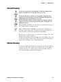
Safety Icons
This section explains how to identify and understand dangers, warnings,
cautions, and notes that are in this manual. You may also see icons that tell
you when to follow ESD procedures and when to take special precautions
for handling optical parts.
A warning alerts you of an operating procedure, practice, condition,
or statement that must be strictly observed to avoid death or serious
injury to the persons working on the equipment.
Avertissement: Un avertissement vous avertit d’une procédure de
fonctionnement, d’une méthode, d’un état ou d’un rapport qui doit
être strictement respecté pour éviter l’occurrence de mort ou de
blessures graves aux personnes manupulant l’équipement.
A caution alerts you to an operating procedure, practice, condition, or
statement that must be strictly observed to prevent equipment damage
or destruction, or corruption or loss of data.
Attention: Une précaution vous avertit d’une procédure de
fonctionnement, d’une méthode, d’un état ou d’un rapport qui doit
être strictement respecté pour empêcher l’endommagement ou la
destruction de l’équipement, ou l’altération ou la perte de données.
Note: Notes either provide extra information about a topic or contain
special instructions for handling a particular condition or set of
circumstances.
x
PK80 Series 80-Column Printer User’s Manual
Before You Begin
Global Services and Support
Warranty Information
To understand the warranty for your Intermec product, visit the Intermec
web site at www.intermec.com and click Service & Support. The Intermec
Global Sales & Service page appears. From the Service & Support menu,
move your pointer over Support, and then click Warranty.
Disclaimer of warranties: The sample code included in this document is
presented for reference only. The code does not necessarily represent
complete, tested programs. The code is provided “as is with all faults.” All
warranties are expressly disclaimed, including the implied warranties of
merchantability and fitness for a particular purpose.
Web Support
Visit the Intermec web site at www.intermec.com to download our current
manuals in PDF format. To order printed versions of the Intermec
manuals, contact your local Intermec representative or distributor.
Visit the Intermec technical knowledge base (Knowledge Central) at
intermec.custhelp.com to review technical information or to request
technical support for your Intermec product.
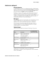
Telephone Support
These services are available from Intermec Technologies Corporation.
In the U.S.A. and Canada
call 1-800-755-5505
and choose this option
Service
Description
Factory Repair and
On-site Repair
Request a return authorization
number for authorized service
center repair, or request an
on-site repair technician.
1
Technical Support
Get technical support on your
Intermec product.
2
Service Contract
Status
Inquire about an existing
3
contract, renew a contract, or ask
invoicing questions.
Schedule Site Surveys Schedule a site survey, or request 4
or Installations
a product or system installation.
Ordering Products
Talk to sales administration,
place an order, or check the
status of your order.
5
Outside the U.S.A. and Canada, contact your local Intermec
representative. To search for your local representative, from the Intermec
web site, click Contact.
PK80 Series 80-Column Printer User’s Manual
xi
Before You Begin
Who Should Read this Manual?
This manual provides you with information about the features of the
PK80 Series 80-Column Printer, and how to install, configure, operate,
maintain, and troubleshoot the printer.
Related Documents
This table contains a list of related Intermec documents and their part
numbers.
Document Title
Part Number
PK80 Series 80-Column Printer Installation Instructions
962-018-022
PK80F 80-Column Printer Quick Start Guide
962-018-021
The Intermec web site at www.intermec.com contains many of our
documents that you can download in PDF format.
To order printed versions of the Intermec manuals, contact your local
Intermec representative or distributor.
xii
PK80 Series 80-Column Printer User’s Manual
1
Introduction
The PK80 Series 80-Column Wireless Printer is used in the route accounting industry to produce high-quality customer invoices, receipts,
load reports, transfers, and other documents. A unique “sleep” feature
saves energy when the printer is not printing, eliminating the ON/OFF
switch. Data input is normally provided by mobile computers.
PK80 Series 80-Column User’s Manual
1
Chapter 1 — Introduction
About the Printer
The Fixed Mount Printer (PK80F) can hang on a wall, on a mounting
plate secured to a wall, or secured directly to a wall. Mobile computers
communicate with this printer through a wireless radio or a wired serial
connection. There is no internal paper tray, thus paper is loaded from a
separate dashboard mount, compact paper tray, or a box. The printer
mechanism is permanently attached inside the printer.
2
PK80 Series 80-Column User’s Manual
Chapter 1 — Introduction
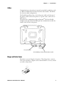
Cables
Communications to the printer is centered around radio technology, such
as a Bluetooth PAN (Personal Area Network) radio module. This will allow for new vehicle configurations.
The Fixed Mount Printer has a 12-volt dc power cable at the bottom of
the printer, which connects the printer to a power source, such as the vehicle battery.
The printer also communicates with an Intermec® 700 Series Mobile
Computer through an RS-232 DB25-pin data communications cable also
found on the bottom of the printer.
DC power cable
RS-232 DB25-pin data communications cable
Hinges on Printer Cover
All printer covers are hinged to the printer. These hinges have a tension
screw (turn clockwise to tighten, turn counterclockwise to loosen), should
you need to adjust them.
PK80 Series 80-Column User’s Manual
3
Chapter 1 — Introduction
Paper
Use of paper that matches the following specifications ensures
optimum PK80 performance. Variation from these specifications, use
of aged paper, or use of paper exposed to elements such as dirt or
humidity may cause printing problems.
The printer works with 1–3 ply carbonless paper that is single-edge glued
and designed for sprocket feed. Standard paper size is 8.5 x 11” or 8.5 x
12” (241 x 305 mm international). Use 3-ply forms up to a maximum of
0.009 inch (0.23 mm) thick.
A soft, flexible, rubber type cement applied to one perforation strip only is
preferred. The resultant lamination should wrap around a 1-1/4 inch diameter roll without curl or wrinkle.
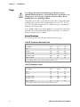
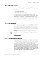
Material Breakdown
The following tables show the material broken down per ply:
14# CBF (Carbonless Back and Front)
Target
Under
Over
Basis Weight
14#
13.3
14.7
Caliper
2.9
2.6
3.2
Moisture
5.0
4.0
6.0
Smoothness (RS)
165
110
230
Smoothness (CB)
270
220
320
Brightness (Wht)
88
86
90
Colors available: White, Canary, Pink, Goldenrod, Blue, Green
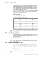
15# CF (Carbonless Front)
Target
Under
Over
Basis Weight
15#
14.43
15.8
Caliper
3.0
2.5
3.2
Moisture
5.0
4.0
6.0
Smoothness (RS)
140
100
180
Smoothness (CF)
140
100
180
Brightness (Wht)
85
84
86
Colors available: White, Canary, Pink, Goldenrod, Blue, Green
4
PK80 Series 80-Column User’s Manual
Chapter 1 — Introduction
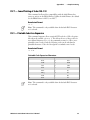
16# CB (Carbonless Back)
Target
Under
Over
Basis Weight
16#
15.2
16.8
Caliper
3.3
2.8
3.8
Moisture
5.7
4.2
6.7
Smoothness (RS)
180
120
270
Smoothness (CB)
270
220
320
Brightness (Wht)
86
84
88
Opacity (Wht)
81
78.5
82
Target
Under
Over
Basis Weight
20#
15.2
16.8
Caliper
4.0
3.8
4.2
Moisture
3.8
4.7
5.0
Smoothness
140
100
170
Brightness (Wht)
94
82
N/A*
Opacity (Wht)
85
84
N/A
20# OCR Laser Bond
* Not Applicable
Caliper Breakdown
The following information show the caliper of forms broken down per ply:
1-Ply (20#)
Targeted: 4.0
Maximum: 4.2
2-Ply (15# and 16#)
Targeted: 6.3
Maximum: 7.0
3-Ply (14#, 15#, and 16#)
Targeted: 9.2
Maximum: 10.2
Printer Dimensions
See the PK80 Series 80-Column Printer Installation Instructions for Fixed
Mount Printer assembly dimensions. Below are the width, length, and
depth dimensions for the Fixed Mount Printer.
Width
10.25” W
(26.04 cm)
PK80 Series 80-Column User’s Manual
Length
14.25” L
(36.20 cm)
Depth
5.00” H
(12.70 cm)
5
Chapter 1 — Introduction
Remote Connections
A printer and a mobile computer, using the Personal Area Network (PAN)
radio, can operate while up to 30 feet (10 meters) apart.
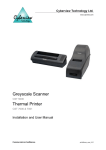
User Panel
The printer user panel is located in the center top of the printer and has
three buttons and two Light-Emitting Diodes (LEDs).
Forward
Button
Reverse
Button
Power LED
Radio Button
Radio LED
Forward and Reverse Buttons
Use the Forward and Reverse buttons as follows:
Forward (Left) Button
S Press this button to power on the printer.
S Press this button to feed one line.
S Press and hold this button longer to feed up to five lines, one line at a
time.
S Press and hold this button longer than five feed lines to do a Form Feed,
which moves the paper to the top of the next page, or form. Press this
button again during a Form Feed to stop the paper feed.
S Press and hold this button longer than a Form Feed to perform a selftest. See Chapter 4, “Troubleshooting,” for more information about this test.
S Press this button any time during a printing job to cancel the current
print job. The print buffer is flushed, all automatic reporting is cancelled, and the printer is ready to print again.
S When there is a paper out, press this button to clear the paper out
mode. Insert the paper, then continue to press this button to feed the
paper into the printer.
Reverse (Right) Button
S Press this button to power on the printer.
S Press and hold this button to do a Back Feed, which pulls the paper
back into the printer line-by-line.
Both Forward and Reverse Buttons
Press both buttons to power off the printer. The current print buffer is
flushed and all automatic reporting is cancelled.
6
PK80 Series 80-Column User’s Manual
Chapter 1 — Introduction
Power LED
The power (left) LED shows a steady green when the power is plugged in
and when the printer is awake after coming out of a sleep mode.
Radio Button
Press the third button, the Radio Button, to toggle the radio on or off.
S If the button is pressed when the RF power is off, then the printer emits
one short beep before turning on the RF power.
S If this button is pressed when the RF power is on, the printer emits two
short beeps before turning off the RF power.
Single Color (Blue) Radio LED
The single-color (blue) radio LED indicator shows the current status of
the RF power for this printer as follows:
Printer State
Radio State
Radio Power State
Asleep
Off
Off
Awake
Off
Off
Asleep
Momentary flash at 1 every 5 seconds
On
Awake
On
On
Single Color (Green) Power LED
The single color (green) LED indicator shows the current status of the
printer power as follows:
Printer State Color LED and Meaning
Asleep
Off
Awake
Green
Vehicle Battery
Power is provided to the printer through a cable permanently installed in
the vehicle. See “Inside Sales” for ordering information and part numbers.
PK80 Series 80-Column User’s Manual
7
Chapter 1 — Introduction
Specifications
Note: Various print fonts do affect the print speed.
Print Speed:
230 cps
Weight:
Fixed Mount Printer:
Mounting plate:
11.15 lbs (5.06 kg)
7.4 lbs (3.36 kg)
Compact paper tray: 5.85 lbs (2.66 kg)
Dashboard mount:
25.95 lbs (11.76 kg)
Temperature:
Operating:
–4_ to 140_ F (–20_to 60_ C)
Storage:
–22_ to 149_ F (–30_ to 65_ C)
Humidity:
Noncondensing:
77_ to 140_ F (25_ to 60_ C) at 90% R.H.
Low condensation:
14_ F (–10_ C) @ 0% R. H. to
High condensation:
140_ F (60_ C) @ 90% R.H.
Altitude:
Operating:
–100 to 5000 meters
Storage:
15,000 meters
Electrical:
8
Voltage:
12 volts dc (nominal)
Current:
100 mA (sleep mode with no charge)
Vibration:
12.5 GRMS for 6 hours @ –31_ to 158_ F (–35_ to 70_ C)
ESD:
Level 4 (15 kV noncontact and 8 kV contact)
PK80 Series 80-Column User’s Manual
Chapter 1 — Introduction
Inside Sales
Contact Inside Sales at 1-800-255-6292 for these supplies:
Cables:
4’ power cable
P/N: 226-215-001
8’ Battery cable
P/N: 206-875-002
16’ Battery cable
P/N: 206-875-006
22’ Battery cable
P/N: 206-875-009
”Y” power cable
P/N: 226-325-001
Y-data DB9 Pwr 3P to DB25
P/N: 321-582-001
Cleaning solutions:
MICRO-CLEAN II
P/N: 901-438-001
Guide Shaft Cleaner
P/N: 901-439-001
Paper:
1-ply:
P/N: 816-027-111
2-ply:
P/N: 816-027-012
3-ply:
P/N: 816-027-013
Ribbon cartridges with:
Black ribbon:
P/N: 805-060-001
Purple ribbon:
P/N: 805-060-002
PK80 Series 80-Column User’s Manual
9
Chapter 1 — Introduction
What’s New
The following information was added since the last release of this publication:
S Updated self-test information in Chapter 4, “Troubleshootting.”
10
PK80 Series 80-Column User’s Manual
2
Operation
This chapter provides instructions how to set up the PK80 Series 80-Column Printer for the first time and lists some common printer behavior.
PK80 Series 80-Column User’s Manual
11
Chapter 2 — Operation
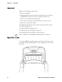
Check List
Make sure the following tasks are done:
S Printer is unpacked.
S Packaging material is removed from around the printer. Save the box
and materials for future use, such as servicing, relocations, etc.
S Twist tie is removed from the print head.
S Power cable is hooked up to the vehicle battery or power source.
S Printer is mounted in the vehicle.
The following tasks must be done. Specific instructions for these tasks are
described on the pages given:
1 Install the ribbon cartridge (page 13).
2 Load the paper into the paper tray (page 15).
3 Feed the paper into the printer (starting on page 19).
Note: Complete these tasks before starting any printer operations.
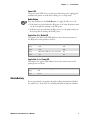
Open the Printer
To open the PK80 Series Printer, place your hands on both corners, fingers under the lips, and lift upwards. To close, simply press down on the
same areas.
12
PK80 Series 80-Column User’s Manual
Chapter 2 — Operation
Install the Ribbon Cartridge
Note: Additional ribbon cartridges are sold separately. See “Inside Sales” in
Chapter 1 for ordering information and part numbers.
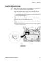
Ensure that the ribbon cartridge is in the printer and is fully seated (cartridge makes a distinct “snap” or “click”) with the visible portion of the
ribbon straight and even before you do any printing.
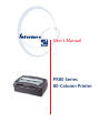
1 Turn the ribbon advance knob (in the direction of the raised arrows) to
remove any slack in the ribbon.
2 Squeeze the ribbon cartridge locking tab into the cartridge, then lower
the cartridge over the print head.
3 Lower the tab side of the cartridge until it clicks.
4 Release the tab and press down on the arrow to fully seat the ribbon cartridge (tab clicks outward).
5 Turn the ribbon advance knob (follow raised arrows) to align the ribbon
in the front of the print head.
4
3
2
1
1 Ribbon
2 Locking tab
3 Advance knob
4 Tightens ribbon
PK80 Series 80-Column User’s Manual
13
Chapter 2 — Operation
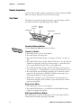
Adjust the Print Head Gap
When the printer is powered on or awakened, the print head will find
“home” by advancing away from home, then returning to home, or by returning to home if starting from another location, such as where it stopped
when the last printing job was complete.
When printing is complete, the print head remains where it stopped with a
low hold energy applied to the print head. Further printing activity begins
from this stopped point. If there is no activity after ten seconds, the print
head returns to its home position and is no longer held in place. If the
print head is moved from this position, the printer will relocate to its
home position before printing again.
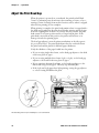
The head gap adjuster is near the printer mechanism on the side opposite
the green thumb wheel. The print head adjuster has five notches between
the print head and the platen for different paper thicknesses.
Verify the thickness of the paper loaded into the printer.
S If you are using single-sheet forms, set the head gap adjuster to the third
notch away from the paper.
S If you are using multiple-sheet forms (2-ply or 3-ply), set the head gap
adjuster to the fourth notch away from the paper.
S If you experience frequent head jams, set the head gap adjuster to the
fifth notch away from the paper. This may stop the head jams.
S If the 2-ply and 3-ply paper have light printing, setting the gap adjuster
to a closer setting will darken the print.
1
5
This illustrating shows the print head adjuster set on its third notch.
14
PK80 Series 80-Column User’s Manual
Chapter 2 — Operation
Fill the Paper Tray
Note: Do not exceed the recommended amounts of paper quantity or
thickness. When loading multiple-sheet paper, be sure to have the original
faced up, with the leading edge towards the rear of the printer.
The Fixed Mount Printer can load paper from a compact paper tray (next
paragraph), a dashboard mount paper tray (page 17), or a separate box.
Fill the Compact Paper Tray
The compact paper tray is designed to hold 6.25” x 8.5” forms. Larger
forms will have to be curved to fit in the paper tray box. The following
instructions are written for 8.5” x 11” forms.
If you are using a compact paper tray to feed paper into the Fixed Mount
Printer, then do the following to load paper into that tray:
1 Hold a stack of paper, up to 2.5 inches (6 cm) thick, with the original on
top. Bend the paper to fit the paper tray.
PK80 Series 80-Column User’s Manual
15
Chapter 2 — Operation
2 Using the open area of the paper tray, lower the paper into the paper
tray, then pull out your hand. The top of the form should be facing up
and be nearest you.
Open area of paper tray
3 Pull the top of the form out and up to the printer. Lift the lid and lay
the paper onto the pinfeed holders. If you are looking at the front of the
form at this point, then the paper is positioned wrong in the paper tray.
16
PK80 Series 80-Column User’s Manual
Chapter 2 — Operation
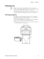
Fill the Dashboard Mount Paper Tray
If you are using a dashboard mount, do the following to load paper:
1 On the front door of the box area of the dashboard mount, pull the two
latches with springs (circled in the following illustration) inwards (part A),
then pull to open the door (part B).
Part A
Squeeze latches
inwards to open
the door.
Part B
PK80 Series 80-Column User’s Manual
17
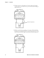
Chapter 2 — Operation
2 With the original facing you, insert a stack of paper inside the box.
3 Squeeze the latches inwards, close the door, release the latches to secure
the door. Pull the top form out through the back, then over the printer
into the mechanism. Paper loading instructions start on the next page.
18
PK80 Series 80-Column User’s Manual
Chapter 2 — Operation
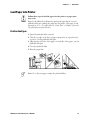
Load Paper into Printer
Follow these steps to load the paper into the printer, or paper jams
may occur.
Paper for the PK80 Series Printer has perforated strips that fit onto the
pinfeed holder pins, guiding the paper into the printer. This paper is sold
separately in 1-, 2-, or 3-ply forms. See “Inside Sales” in Chapter 1 for ordering information and part numbers.
Position the Paper
1 Open the pinfeed holders outward.
2 Take the top edge of the sheet of paper and position it, original side facing down, over the pinfeed holder pins.
3 Align the first few holes of the paper, on each side of the paper, onto the
pinfeed holder pins.
4 Close the pinfeed holders.
5 Raise the paper bail.
Note: Go to the next page to adjust the pinfeed holders.
PK80 Series 80-Column User’s Manual
19
Chapter 2 — Operation
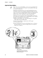
Adjust the Pinfeed Holders
Note: There are two pinfeed holders, one next to the green thumb wheel
and one opposite the same wheel. Always loosen the pinfeed holder opposite the green thumb wheel.
Adjusting the pinfeed holder next to the green thumb wheel may cause
information to print in the wrong place. If this pinfeed holder is moved,
correct its location by releasing the pinfeed holder tab, moving the pinfeed
holder as close to the green thumb wheel as possible, then locking the
pinfeed holder tab, before adjusting the opposite pinfeed holder.
If the paper does not properly fit on the two pinfeed holders Follow these
steps to adjust the area between the two pinfeed holders to fit the width of
the paper. See the illustration on the next page.
1 With the pinfeed holders open, release the locking tab on the pinfeed
holder opposite the green thumb wheel.
2 Adjust the pinfeed holders to align the pins with the paper.
3 Close the pinfeed holder.
4 Ensure that the paper is smooth (no folds, bulges, bows, etc.) between
the pinfeed holders. If so, push the locking tab down on the pinfeed
holder that you adjusted.
1
2
3
4
1 Pinfeed holder
2 Locked pinfeed holder locking tab
3 Released pinfeed holder locking tab
4 Thumb wheel (green)
20
PK80 Series 80-Column User’s Manual
Chapter 2 — Operation
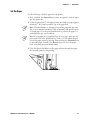
Set the Paper
Do the following to feed the paper into the printer:
1 Press, and hold, the Forward button on the user panel to feed the paper
into the printer (6).
2 Lower the paper bail (7). An empty printer autofeeds new paper approximately 0.1” (0.25 cm) beyond the top of the paper bail.
Note: The ideal distance to feed paper beyond the paper bail may vary
due to environmental conditions (such as humidity) and specific aspects
of certain paper. Use the green thumb wheel to position the paper to a
desired distance per your conditions.
Note: If your paper has a preprinted logo on every page, make sure the
print head is below the preprinted logo. If not, you can adjust the position of the paper, either by pressing, then releasing, the Forward button
to move the paper forward or the Reverse button to move the paper
back, or by using the green thumb wheel.
3 Close the printer lid. Make sure the paper will pass through the paper
slot when the printer starts printing.
PK80 Series 80-Column User’s Manual
21
Chapter 2 — Operation
Printer Behavior
This lists behaviors you can expect when working with your printer.
Expectations
Below are some tips to remember when working with Bluetooth:
S The Bluetooth connection is automatically closed when the printer falls
asleep.
S The Bluetooth connection is automatically closed when there has been
no Bluetooth activity for a period of time. You can configure this period
of time via the {BL:xxx} command, where “xxx” ranges from 60 to
65535 seconds (1 minute to more than 18 hours).
S For the Bluetooth Query, add the “I” parameter, which responds with
the inactivity timer specified in the previous bullet.
See Appendix A, “Commands” for more information about the “I” parameter and the inactivity timer.
Indicators
If the power LED is green, but the printer is not printing, press and hold
both the Forward and Reverse buttons. If the power LED lights up, refer
to the following table:
Printer Failure Indicators
Sets of Beeps
Meaning
1 set of 13 beeps
Configuration error.
2 sets of 3 beeps
Paper Out.
3 sets of 4 beeps
Home switch failure.
4 sets of 2 beeps
Head Jam.
4 sets of 4 beeps
Flash write error.
12 sets of 12 beeps Operating system software failure.
22
PK80 Series 80-Column User’s Manual
Chapter 2 — Operation
Printer Runs Out of Paper
When a paper outage occurs, the printer emits three short beeps, pauses,
then emits three more short beeps to indicate the printer is out of paper.
Below is what you should expect when you do any of the following:
Do nothing
The printer times out, reports a “Time Out” status, cancels the print
job, and cancels automatic reporting.
Insert paper before the printer times out
The printer reports a “Paper In” status and resumes printing.
Stop the print job — press the Forward button
The printer reports a “Kill Job” status, flushes the print buffer, cancels
automatic reporting, and readies for another print job.
Turn off the printer — press both the Forward and Reverse buttons
The printer reports a “Printer Off” status, flushes the print buffer, cancels automatic reporting, and shuts down.
See Chapter 1, “Introduction,” for information about the Forward and Reverse buttons on the control panel.
The printer reports all activity to the print job status report described on
the next page.
Printer Head Jams
When the printer head jams, the printer emits two short beeps, pauses,
emits two more beeps, pauses again, and continues until it emits eight
beeps in all. What to expect when you do one of the following:
Do nothing
The printer times out, reports a “Time Out” status, cancels the print
job, and cancels automatic reporting.
Stop the print job — press the Forward button
The printer reports a “Kill Job” status, flushes the print buffer, cancels
automatic reporting, and readies for another print job after the print
head jam is cleared.
Turn off the printer — press both the Forward and Reverse buttons
The printer reports a “Printer Off” status, flushes the print buffer, cancels automatic reporting, and shuts down.
See Chapter 1, “Introduction,” for information about the Forward and Reverse buttons on the control panel.
Go to page 14 for information about the print head.
The printer sends all activity to the print job status report described on the
next page.
PK80 Series 80-Column User’s Manual
23
Chapter 2 — Operation
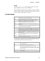
Print Job Status Report
This simple protocol assures that data delivered to the printer is printed
without mechanical error. Each print job to be monitored begins with an
“ESC s n” command, where the “ESCs” marks the start of the print job,
and bit fields within “n” specify the level of error reporting. The end of
the print job is marked by an “ESC e” command.
Note: Spaces are not part of the actual sequences. They are only included
here for readability.
Once the print job status is enabled, any detection of a requested condition (see the definition of “n” below) is reported immediately, without the
need to query the printer. The printer will send the same string that results
from receipt of a status command (ESC{ST?}). In addition, if requested,
the printer will automatically send the status when the last print line or
FormFeed within the start/end markers is complete.
S ESC s n Start of print job (0x1B 0x73 n)
Set to report status at end of job
Set to report paper out
Set to report print head jam
Set to report when paper is present after paper out
Set to report timeout during print
Set to report fwd/rev key presses during print
Must be zero (reserved)
Note: An n of all zeroes (0x00) will cancel any active auto status messages
set by a previous ESC s n without an ESC e.
S ESC e End of print job (0x1B 0x65)
Response is identical to the status command with Paper Jam and Print Status fields added. Status can still be requested by sending the usual sequence
(ESC{ST?}). See Appendix A, ”Commands,” for information.
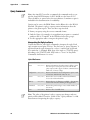
Timing Out
When a time out occurs (ESC{BLI}), a status request is sent indicating the
printer has timed out. The current print buffer is flushed, and subsequent
automatic reporting is cancelled.
The printer will not time out if the sixth bit is set (cancel timeout) when
the ESC s n command is sent to mark the beginning of the print job. If
the job has completed printing and the printer is idle, then pressing the
Forward button on the control panel will not send the “print job kill”
message, since there is nothing in the print buffer.
However, pressing both the Forward and Reverse buttons to turn the
printer off will generate the printer off message.
24
PK80 Series 80-Column User’s Manual
3
Maintenance
The printer lasts longer and performs better when it is operated correctly
and kept clean.
PK80 Series 80-Column User’s Manual
25
Chapter 3 — Maintenance
Operation Guidelines
Do
Ensure that the computer remains connected to the printer throughout printing or operation.
Make sure the printer cover is closed (except during maintenance or when loading paper).
Ensure there is paper properly installed in the paper tray or dashboard mount.
Disconnect the printer power cable when jump-starting the vehicle.
Clean the external surface of the printer using a soft cloth moistened with mild soap and water, a good quality
cleaner, such as MICRO-CLEAN II, and if necessary, rubbing alcohol.
Make sure your printer is loaded with paper before communicating with your mobile computer.
Do Not
Spill liquids or food crumbs into the printer.
Sit or stand on the printer.
Use solvents or abrasive cleaners on the printer.
Rest objects on, under, or against the printer.
Allow the printer to be knocked over or physically damaged.
Start or stop the vehicle engine while printing.
Overload paper tray (paper jams will occur).
Use objects to remove paper from between the print head and platen (damage to mask spring/ print head will occur).
26
PK80 Series 80-Column User’s Manual
Chapter 3 — Maintenance
General Cleaning
Do not use glass cleaners with ammonia. Permanent damage to the
printer cover will occur if such glass cleaners are used.
Do not use abrasives or solvents (or any product containing these
substances) to clean any part of the unit. Permanent damage to the
printer will occur if such substances are used.
Never use ketonic solvents (acetone or ketone) or aromatic solvents
(toluene or xylene) to clean any part of the printer. Doing this can
damage the printer.
Note: MICRO-CLEAN II is the only cleaner recommended for this purpose. Other cleaners can damage the case.
Note: GUIDE SHAFT CLEANER is recommended for cleaning your
80-column printer guide shafts. Cleaning the printer guide shaft can reduce the number of head jams caused by dirt and buildup.
Both cleaners are sold separately. See “Inside Sales” in Chapter 1 for ordering information and part numbers.
Periodic cleaning helps maintain the appearance and reliability of the printer. When cleaning the printer, inspect both the outside and the inside for
obvious signs of damage, wear, or impending failure.
Outside Cleaning
Do not pour liquid cleaners directly on the printer case. Instead, dampen a
soft, lint-free cloth with a quality cleaner and clean the exterior surfaces
with this cloth. Do not use solvent solutions. Inspect all cables and the remote terminal holder or vehicle dock for damage.
PK80 Series 80-Column User’s Manual
27
Chapter 3 — Maintenance
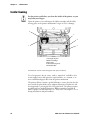
Inside Cleaning
Let the printer cool before you clean the inside of the printer, or you
may burn your fingers.
Open the printer cover and inspect the ribbon cartridge and all visible
moving parts on the printer mechanism for signs of wear or damage.
2
3
4
1
5
1 Head gap adjuster
2 Ribbon cartridge
3 Paper bail
4 Thumb wheel (green)
5 Pinfeed holder
This illustration shows the visible moving parts of the printer mechanism.
Use a low-pressure, dry air source, such as “canned air” available at electronic supply houses and typewriter repair facilities, or a vacuum, to remove accumulated paper dust from the printer mechanism.
The printer ribbon contains a special lubricant to ensure that the fine dot
wires inside the print head receive adequate lubrication. Replace the ribbon frequently to prolong the life of the print head. The printer requires
no additional user-applied lubrication. Ribbon cartridges, available in
black or purple, are sold separately. See “Inside Sales” in Chapter 1 for ordering information and part numbers.
28
PK80 Series 80-Column User’s Manual
Chapter 3 — Maintenance
Old Ribbon Cartridge Removal
Physically move the print head mechanism to an open area, then do the
following to remove the old ribbon cartridge:
1 Squeeze the ribbon cartridge locking tab (on the side of the cartridge)
against the ribbon cartridge.
2 Lift the ribbon cartridge to remove the ribbon from the print head. Ensure the ribbon does not catch.
3 Lift the ribbon cartridge out of the printer.
Locking Tab
PK80 Series 80-Column User’s Manual
29
Chapter 3 — Maintenance
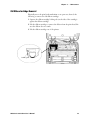
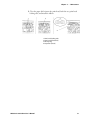
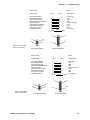
Mask Spring Cleaning
Look at the mask spring behind the print head. If the mask spring needs to
be cleaned, go on to the next page. If the mask spring appears to be in
good condition, install a new ribbon cartridge as described on page 13.
1
2
1 Print head
2 Mask spring
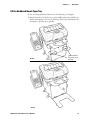
Do the following to clean the mask spring:
1 Unlatch the print head locking tabs to release the print head, lift the
print head and set aside, then lift up the paper bail. Do not detach the
print head unit.
Never use a sharp object, such as pinchers, to clean between the
print head and the platen (rubber roller). This can damage the mask
spring and print head.
2 Remove the clear plastic paper guide that seats the mask spring, if necessary. Use your fingernails to loosen the base of the paper guide, then
pull the paper guide straight up from the printer mechanism.
3 Remove the metal mask spring from the paper guide and clean with a
quality cleaner. Replace if damaged.
4 Put the good, clean mask spring into the paper guide and install the paper guide into the printer.
30
PK80 Series 80-Column User’s Manual
Chapter 3 — Maintenance
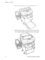
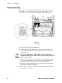
5 Close the paper bail, reinsert the print head, latch the two print head
locking tabs, and install the ribbon.
1
2
3
4
1 Print head locking tabs
2 Print head (lifted aside)
3 Mask spring
4 Paper bail (raised)
PK80 Series 80-Column User’s Manual
31
Chapter 3 — Maintenance
32
PK80 Series 80-Column User’s Manual
4
Troubleshooting
This chapter helps you correct printing problems that may occur. If you
experience a printing problem, you can perform several tests to find and
possibly cure the problem.
PK80 Series 80-Column User’s Manual
33
Chapter 4 — Troubleshooting
Check the Power Source
The printer will automatically power down after a configurable period of
inactivity. Activity is either sending data or pressing a button. The timer
resets during printing. You can awake the printer either by sending data or
pressing either the Forward or the Reverse button on the user panel.
If there is power, the power LED turns on and the print head moves to its
“home” or starting position. If the printer emits beeps and power LED
lights up or flashes, observe the number of beeps and flashes and refer to
the table on page 38 for an error message.
If there is no reaction from the printer after pressing a button on the user
panel, or only the power LED blinks, verify that the power cables are
properly connected between the printer and its power source (internal battery, vehicle cable, or ac). If neither of these steps “wake” up the problem
printer, then return the printer for service.
Vehicle cable:
Attach the printer to another vehicle power cable.
AC power:
Plug the printer into another outlet.
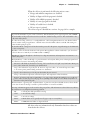
Large Print Jobs
Printing large files with 15 pages or more can cause lost data issues because
of limited printer buffer size and time out length on the mobile computer.
To prevent problems, you can adjust the time out lengths on the mobile
computer. If you encounter a problem concerning large print jobs, contact
Customer Support at 800-755-5505 for further help
Printer Cold-Boot
Should you need to reset the Fixed Mount Printer, simply remove power
from the printer, wait a few moments, then return power to the printer.
Self-Test
Note: Each time the printer is powered up, it reads flash values into RAM.
As long as the printer is on and awake, it updates those values in RAM.
When the printer is powered off, or falls asleep, the values are written into
flash. If power is disconnected instead of the printer being powered off or
falling asleep, then updates in RAM are lost.
Press and hold the Forward button through a form feed (more than five
lines). If it is still held down at the end of the form feed, it prints the selftest. Internal tests are performed and a 1-page report is printed. This report provides helpful tips in diagnosing/troubleshooting printer problems.
Note: You can abort the self-test by pressing a button while it is printing.
34
PK80 Series 80-Column User’s Manual
Chapter 4 — Troubleshooting
When the self-test is performed, the following actions occur:
S Voltage and ambient temperature are obtained
S Validity of diagnostic block program is checked
S Validity of BootBlock program is checked
S Validity of control program is checked
S Validity of loaded fonts is checked
S Self-test report is printed
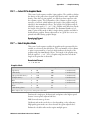
The self-test report is divided into sections. See page 36 for a sample.
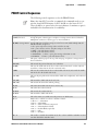
The printer model number is given on line 1 (first line). This identifies the printer type being used, such as PK80F.
The serial number of the printer is listed on line 3 under the “Serial#” heading on line 2. The serial number is also
on the inside of the printer.
The “Auto Feed” setting, on line 13, is a configurable item. “CR” Carriage Return means no auto linefeed. This is
the most common setting for applications. “CR+LF” means a linefeed will be added to each CR. This setting can
produce double-spacing of reports.
The “Interface Mode” setting, line 14, lists the interface protocol for the printer. A typical setting can be DTR with
no, odd, or even parity.
“Baud Rate” on line 16, lists the baud rate for the printer. Most application software autobauds so you do not have
to select it. Bit rate is commonly set to 19200 (19.2K) or 9600 bps.
“A2D History,” lines 63 through 66, is the history for voltage measurements and temperature measurements, as recorded by the printer.
“Head Jam History” on lines 68 through 71, gives information on head jams. If the printer is having frequent head
jams, these lines can assist in determining the problem.
“Direction” tells which way the head was moving, “left” toward home and “right” away from home. Home position is at the extreme left, toward the green thumb wheel.
“Step” is the acceleration step at the jam. “0” means no steps were taken, “15” means all steps were taken.
“1–14” means printer jammed during acceleration or deceleration.
“Speed” is the acceleration speed of the print head when the jam occurred.
“Temp” is the ambient temperature at the last head jam. The temperature is listed in Celsius.
“Position” of carriage at the jam in 1/720 inches = 12 * step position. Divide the number by 12 to get the step
position. There are 512 steps across the page. If it is jamming in the middle, it is more likely a dirty ribbon or
obstruction in the print head’s path.
“Head Dot Pattern,” appearing after “Total Head Jams,” is printed to verify the individual dot wires. There should
be nine dots. If some are missing, it could be a print head failure or a circuit board failure.
“Error Log” information appears in the second-to-last group of lines, This information is cleared after every self-test.
This information is very helpful in determining problems.
“HJ”
# of head jams while print head is moving
“12Vu”
# 12-volt under voltage
“12Vo”
# 12-volt over voltage
“Home”
# Home detect errors (typically caused by paper scraps or circuit failures)
“EEErr”
# EEPROM write failures to diagnostic block
All other values are informational only. Remember that these values are
cleared after the self-test.
PK80 Series 80-Column User’s Manual
35
Chapter 4 — Troubleshooting
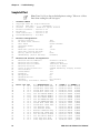
Sample Self-Test
Note: Lines 10–19 are factory-default printer settings. Take note of these
lines when reading the self-test report.
1
2
3
4
5
6
7
8
9
10
11
12
13
14
15
16
17
18
19
20
21
22
23
24
25
26
27
28
29
30
31
32
33
34
35
36
37
38
39
40
41
42
43
44
45
46
47
48
49
50
51
52
53
54
36
Intermec PK80F
Copyright 2003 All Rights Reserved
Serial#
MFG Date –––––––––Hardware–––––––––
1234567
01/24/05
PK80F 8in Impact Printer
Printer Firmware: – Version 5.54
BootBlock:
– Version 5.06
Comm Controller: – Version 5.30
Flash/RAM Memory: – 8/4 Mbit
Printer Configuration:
Printer Timeout:
RF Power Down Timeout:
Auto Feed:
Interface Mode:
Beeper:
Baud Rate (Serial RS-232):
Data Bits (Serial RS-232):
Parity (Serial RS-232):
Handshaking (Serial RS-232):
60S
Never
CR=CR LF=CRLF
LP
On
19.2K
8
None
Hardware
Wireless RF Printer Configuration:
Wireless Device Address:
00:80:37:19:3A:23
Wireless Device Name:
“PK80–1234567”
Wireless Service Name:
“Wireless Printer”
Wireless Profile:
Serial Port (SPP)
Class of Device/Service:
040680 Rendering Imaging Printer
Discoverable:
Yes
Connectable:
Yes
Bondable:
Yes
Encryption:
No
Authentication:
No
Passkey:
Key present
Inactivity Disconnect Timeout: 60S
Fonts: LOC
R
R
R
R
D
D
D
D
D
D
D
D
D
D
D
D
D
D
D
CPI
10.5
12.7
10.5
12.7
Vary
Vary
Vary
10.5
10.5
10.5
12.7
10.5
12.7
10.5
10.5
10.5
10.5
10.5
12.7
*–––DESCRIPTION–––*
255CH PICA CP437 REG
255CH ELIT CP437 REG
255CH PICA CP437 ITA
255CH ELIT CP437 ITA
224 CH TRADTN ARABIC
224 CH SMPLFD ARABIC
224 CH E-MAPD ARABIC
224 CH GREEK-DOS MAP
224 CH GREEK-WIN MAP
255CH PICA ISO01 REG
255CH ELIT ISO01 REG
ISO 8859-09 PICA
ISO 8859-09 ELITE
Hebrew ISO8859-8 Map
Hebrew DOS CP862 Map
254 CH CYRILC CP-866
255 CH CYRILC 8859-5
Code Page 852 PICA
Code Page 852 ELITE
V
3
3
3
3
4
4
4
3
4
2
2
2
2
2
2
3
3
2
2
*–DATE–*
02/06/03
02/06/03
02/06/03
02/06/03
06/20/01
07/11/01
07/11/01
02/01/01
02/01/01
10/30/01
10/30/01
04/18/03
04/18/03
09/29/03
09/29/03
03/27/01
03/27/01
05/13/02
10/28/02
*–––NAMES–––*
PR437 A(41H)
ER437 B(42H)
PI437 C(43H)
EI437 D(44H)
ARABT d(64H)
ARABS e(65H)
ARABE f(66H)
GRDOS g(67H)
GRWIN h(68H)
ISO10 i(69H)
ISO12 j(6AH)
PRI09 l(6CH)
ERI09 k(6BH)
HBISO m(6DH)
HBDOS n(6EH)
CY110 +(2BH)
CY210 -(2DH)
DL210 ^(5EH)
DL212 _(5FH)
PK80 Series 80-Column User’s Manual
Chapter 4 — Troubleshooting
55
56
57
58
59
60
61
62
63
64
65
66
67
68
69
70
71
72
73
74
D
9.0
DOS10 W/ EURO @ 0x7F
Current Statistics:
Battery Voltage:
Total Pages:
Cold Starts:
Warm Starts:
A2D History
Curr
12V:
13.20
000
05/17/02 DOS10
p(70H)
13.2V
205
56
1345
Low
00.00
000
Head Jam History
Total Head Jams:
Motion Direction
Print Right
4
1
Ramp
Const
High
00.00
000
Step
000
Min
Max
07.00 16.80
000
000
Speed Temp
High +00.0C
Error
00.00
000
Page
00000
Count
00000
Position Page
00708
00183
Head Dot Pattern
75
76 Error Log
77 HJ
12Vu
12Vo
Home
EEErr
78 00000 00000 00000 00000
00000
79
60 !#$%&()*+:;<=>?ABCDEFGHIJKLMNOPQRSTUVWXYZabcdefghijklmnopqrstuvwxyz01234567890
61 #$%&()*+:;<=>?ABCDEFGHIJKLMNOPQRSTUVWXYZabcdefghijklmnopqrstuvwxyz01234567890!
62 $%&()*+:;<=>?ABCDEFGHIJKLMNOPQRSTUVWXYZabcdefghijklmnopqrstuvwxyz01234567890!#
63%&()*+:;<=>?ABCDEFGHIJKLMNOPQRSTUVWXYZabcdefghijklmnopqrstuvwxyz01234567890!#$
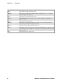
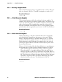
Report Failure
If a partial report generates and a printer error occurs during printing,
refer to the table on the next page for troubleshooting help.
If the printer does not generate a report:
S There may be a printer failure, refer to the troubleshooting table on
the next page for possible solutions.
S There may be a power failure, check the power source (internal battery, charge cable, or ac adaptor).
PK80 Series 80-Column User’s Manual
37
Chapter 4 — Troubleshooting
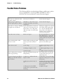
Possible Printer Problems
The following table lists actual printing problems, possible causes, and actions you should take to correct a problem. Call 800-755-5505 or
425-356-1799 if you are advised to contact Customer Support.
Symptom
Test or Cause
Solution
Printer does not communicate with
the mobile computer.
Incorrect protocol selection.
Contact Customer Support.
Double-spacing on application reports but single-spacing on self-test.
Check line 11 on the self-test report,
if “CF+LF” then this is an incorrect
configuration.
Contact Customer Support.
Printer emits 1 or 2 beeps or blinking Printer mechanism does not have adgreen light is the only indicator.
equate power for printing. The 12 V
may be under or over voltage fault.
(Note: Error lights do not flash if high
voltage.)
Check power supply if one is used. If
power supply, adjust supply voltage
to 11–15 volts. Check the vehicle
charge cable (see the PK8X Series
80-Column Printer Installation Instructions for information).
Printer emits 2 sets of 3 beeps
Printer out of paper.
Press the Forward button to stop the
beeps. Reload paper — see page 15
for instructions. If the “paper out”
condition still exists, the printer will
beep again.
Printer works but either or both
LEDs do not work.
Discrete cable connecting user panel
board to pivot frame assembly is
loose.
Call Customer Support or send the
printer in for hardware repair.
Printer does not work.
(1) No voltage.
(1) Adjust supply voltage to 11–15
volts.
(2) Voltage too high or too low.
(2) Adjust supply voltage to 11–15
volts.
(3) No data input.
(3) Tighten computer connections.
Printer is emitting 4 sets of 2 beeps
and has stopped printing.
The printer had detected a paper jam Power off the printer, clear the jam
during homing.
as advised below, then power on or
awaken the printer.
No paper feed (paper jam). When I
pull the paper toward the roller the
paper is resistant.
(1) Paper tray or dashboard mount
may be too full.
(1) Ensure there are fewer than 200
3-ply sheets in the paper tray or dashboard mount.
(2) The paper perforation may be
torn.
(2) Remove the torn paper, load and
center a clean stack of paper, and adjust the pinfeed holders. See page 20
for instructions.
(3) The paper may be wrinkled,
creased, moist, or perforations may
be missing.
(3) Replace the paper.
38
PK80 Series 80-Column User’s Manual
Chapter 4 — Troubleshooting
Symptom
Test or Cause
Solution
No paper feed (head jam). When I
move the print head manually from
side to side, the print head is resistant.
(1) Ribbon may be jammed.
(1) Remove ribbon cartridge and
turn knob. If ribbon resists, replace
ribbon cartridge. See page 13 for instructions.
(2) Mask spring may be bent or dam- (2) Replace the mask spring. See page
aged.
30 for instructions.
(3) Print head gap adjuster may be
too low.
(3) Set the head gap adjuster to the
fifth notch away from the paper. See
page 14 for instructions.
(4) Paper scraps are found in the
printer mechanism or around platen.
(4) If the ribbon cartridge bumps
against the inside of the printer,
check the white ribbon cable, home
position sensor, and four screws. Remove any paper scraps and do a
cleaning.
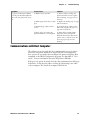
Communications with Host Computer
The self-test report can verify that the communications protocol options
selected for the printer match those expected by the host computer. If
these options do not match, then reconfigure the printer using Easy Print
commands or the PK80 Configuration program. See Appendix A, “Commands,” for more information about the Easy Print commands.
If the protocol options do match, then the data communications cable may
be defective. Verify that the cable is working by substituting a new cable
or host computer. Also check the computer vehicle dock.
PK80 Series 80-Column User’s Manual
39
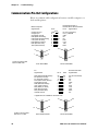
Chapter 4 — Troubleshooting
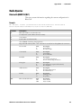
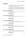
Communications Pin-Out Configurations
Below are common cable configurations between a mobile computer or a
dock and the printer:
Fixed Mount Printer or
Remote Mount Terminal Holder
Pin #
Signal Name
Mobile Computer
Signal Name
Pin #
Chassis Ground
Charge Input
SG (Signal Ground)
DSR (Data Set Ready)
DTR (Data Terminal Ready)
CTS (Clear To Send)
RTS (Ready To Send)
RXD (Receive Data)
TXD (Transmit Data)
shell
8
9
7
2
6
3
5
4
8
15
1
9
15-Pin to 25-Pin Cable
P/N: 216-605-XXX
shield
1
9
7
6
20
5
4
3
2
NC (No Connection)
HHC_CHARGE
GND
NC
NC
RTS
CTS
TXD
RXD
13
25
1
14
25-Pin DSUB Male
15-Pin DSUB Male
Fixed Mount Printer
PC
Signal Name
Pin #
Pin #
Signal Name
DTR (Data Terminal Ready)*
RC (Receive Carrier)*
TC (Transmit Carrier)*
DCD (Data Carrier Detect)*
SG (Signal Ground)
DSR (Data Set Ready)*
CTS (Clear To Send)
RTS (Ready To Send)
RXD (Receive Data)
TXD (Transmit Data)
Chassis Ground
20
17
15
8
7
6
5
4
3
2
1
20
17
15
8
7
6
5
4
3
2
1
NC (No Connection)
NC
NC
NC
GND
NC
RTS
CTS
TXD
RXD
NC
* Signals are not available on the 6100 Dock
1
13
25-Pin to 25-Pin Cable
P/N: 216-771-XXX
40
14
25
25-Pin DSUB Female
13
25
1
14
25-Pin DSUB Male
PK80 Series 80-Column User’s Manual
Chapter 4 — Troubleshooting
Vehicle Dock
Printer
Signal Name
Pin #
CD (Carrier Detect)
RXD (Receive Data)
TXD (Transmit Data)
DTR (Data Terminal Ready)
Chassis Ground
DSR (Data Send Ready)
RTS (Ready To Send)
CTS (Clear To Send)
RI (Ring Indicator)
1
2
3
4
5
6
7
8
9
shell
Pin #
Signal Name
3
2
20
7
6
4
5
No Charge
TXD
RXD
DSR
Chassis Ground
DTR
CTS
RTS
No Charge
shield
shell
1
1
6
9
5
9-Pin to 25-Pin Cable
P/N: 321-355-XXX
14
25
13
9-Pin DSUB Female
25-Pin DSUB Male
Vehicle Dock
Printer
Signal Name
Pin #
CD (Carrier Detect)
RXD (Receive Data)
TXD (Transmit Data)
DTR (Data Terminal Ready)
Chassis Ground
DSR (Data Send Ready)
RTS (Ready To Send)
CTS (Clear To Send)
RI (Ring Indicator)
1
2
3
4
5
6
7
8
9
shell
shield
Pin #
Signal Name
3
2
20
7
6
4
5
No Charge
TXD
RXD
DSR
Chassis Ground
DTR
CTS
RTS
No Charge
shell
1
1
5
9-Pin to 25-Pin Cable
P/N: 321-582-XXX
6
9
9-Pin DSUB Female
PK80 Series 80-Column User’s Manual
14
25
13
25-Pin DSUB Male
41
Chapter 4 — Troubleshooting
The printer has a 25-pin connector with the following pinout designations
and signal mnemonics:
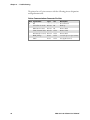
Printer Communications Connector Pin-Outs
42
DB25 Signal Name
Type
I/O
Description
20
NC
— — — — — — No Connection
4
CTS (Clear To Send)
RS-232
IN
Wake up
2
RXD (Receive Data)
RS-232
IN
Printer’s RxD
3
TXD (Transmit Data) RS-232
OUT
Printer’s TxD
5
RTS (Ready To Send) RS-232
OUT
Printer’s RTS
9
HHC_Charge
Power
OUT
11–15 V, up to 1 A per contact
7
GND
Power
OUT
SG (Signal Ground)
PK80 Series 80-Column User’s Manual
A
Commands
This appendix lists Easy Print and Bluetooth configuration and query
commands and control sequences that are supported by the PK80 Series
80-Column Printer.
Note: Printer configuration applications may not determine printer communication speed if the printer is out of paper. Make sure the printer has
paper when doing reconfiguration and firmware upgrading.
PK80 Series 80-Column Printer User’s Manual
43
Appendix A — Commands
Commands
Below are the commands and the pages where their information begins:
S Bluetooth Wireless Configuration (next paragraph)
S Easy Print (page 45)
S Query (page 46)
Some of these commands are identified as Easy Print commands, which
must be preceded by ESC EZ. Printers must also receive the “{” as part of
the ESC EZ sequence to be placed into Easy Print mode.
Bluetooth Wireless Configuration Commands
All commands are enclosed in ‘{’ and ‘}’. They begin with three letters; if
there is data that follows the letters are terminated with a colon “:”. Each
parameter can be configured is identified by a unique letter, followed by a
colon, followed by the data for that parameter. If the configuration type
permits, multiple parameters can be changed in one command by separating them with a semicolon “;”. All commands must be sent in uppercase..
Spaces in the data are not allowed unless they are part of the data.
After receiving the command, the data is written to flash and the printer
restarts using the new values. This all takes less than one second.
1 Configure default values. ALL configuration parameters can reset to
their original default (non-printer specific) values by sending “{CDV}” Configure Default Values
2 Configure Bluetooth. As of this date, only the Bluetooth Friendly Name
can be reconfigured by sending a command of the form
“{CBT:<parms>}”
S F: <data> for Friendly Name (Device Name)
Send up to 16 characters.
S D: <data> for Discoverable (<data> = Y/N)
S C: <data> for Connectable (<data> = Y/N)
S B: <data> for Bondable (<data> = Y/N)
S E: <data> for Encryption (<data> = Y/N)
S A: <data> for Authentication (<data> = Y/N)
S P: <data> for Passkey
Send up to 16 characters (default passkey is “passkey”)
S I: for Inactivity Timeout (see pages 22 and 55 for more information)
44
PK80 Series 80-Column Printer User’s Manual
Appendix A — Commands
Example
ESC EZ{CBT:F:MyPrinter} would configure the Bluetooth Friendly
Name (AKA Bluetooth Device Name) to MyPrinter.
ESC EZ{CBT:F:BTPrinter;D:N;C:Y;E:Y;A:Y;P:Passkey1} would
configure the Bluetooth Device Name to BTPrinter, the printer would not
be discoverable but would be connectable, encryption can be used, authentication is required, and the passkey is ”Passkey1”.
Easy Print Commands
{CT:nnn}
Configures the timeout where nnn can be 15–9998 seconds. 9999 seconds will cause the printer to NEVER timeout.
{CB:n}
Configures the baud rate where n corresponds to the desired baud rate:
0=1200, 1=2400, 2=4800, 3=9600, 4=19.2K (19200), 5=38.4K
(38400), 6=57.6K (57600), and 7=115.2K (115200).
{CN:n}
Configures the number of data bits where n can be 7 or 8
{CP:n}
Configures parity, where n can be N (no parity), E (even parity), or
O (odd parity).
{CC:n}
Configures the carriage return to automatically add LF to CR, where n
can be N for CR=CR, or Y for CR=CRLF.
{COMMIT} None of the two letter configuration commands will take affect until the
COMMIT command is sent. When {COMMIT} is sent, the values are
written to flash and the printer is restarted. When it restarts, it will use
the default configuration, which in most printers is NOT Easy Print. To
do additional configuration, you will need to put the printer back into
Easy Print mode.
{CH:n}
Configures handshaking. Valid values are None (N), Hardware(H),
Software(S), or Both(B)
{CR:nn}
Configures the radio timeout. Values of 0 or 65535 disable the radio
timeout. Other valid values are 1–65534.
The following are configurable and the state will be indicated on the self
test printout, but they have no operational effect yet.
{CS:n}
Configures the beeper either ON or OFF where n=Y for beeper
ON or N for beeper off.
{LP}
This returns the printer to a line printer mode.
{S}
This returns a status command. The response is of the
{U:1234;P;D;O;RDY} form where the P position indicates paper is
present and an N in the same position indicates no paper. All other
characters are fixed.
{IPL: 0xAA 0x55} This jumps the printer to the boot code for erasure and subsequent downloads.
PK80 Series 80-Column Printer User’s Manual
45
Appendix A — Commands
Query Commands
Note: Any time ESC is used in a command, the command needs to contain the actual ASCII character for ESC (0x1B), not the letters E-S-C.
There should be no spaces before the next character. Sometimes a space is
included in the documentation for readability.
Queries can be sent to the PK80 Printer via the Bluetooth or the RS-232
data link. The printer’s reply to a query returns information about the
printer or the print request. There are three steps involved:
1 Frame your query using the correct command format.
2 Send the Query (for example, via an applications program or a terminal
emulator such as “Terminal” in the Windows Accessories group).
3 Use the appropriate table to interpret the printer’s reply.
Interpreting the Reply to a Query
Consult the table for each Query command to interpret the reply. Each
reply contains several pairs of letters. The first letter or “query character” is
separated from the reply character by a colon (:) and the pair is followed
by a semicolon (;). Example: E:N; (part of the reply to a STATUS query).
According to the STATUS table, the E refers to “errors“ in Easy Print
Commands. An N means “no errors.”
Quick Reference
Command
Format
Description
Status
ESC{ST?} Returns information about the printer’s ability to print
the next report, and reports any errors from the last
print request, such as paper condition, command errors,
buffer size, or battery voltage.
Configuration ESC{CF?} Returns information about configuration options, such
as baud rate, default mode, time-out, etc.
Version
ESC{VR?} Returns the version number of the loaded firmware,
boot code, and download files.
Memory
ESC{MY?} Returns the size of all memory available — the amount
used and the amount remaining for the application.
Print Head
ESC{PH?} Returns the print head type in use and the number of
dots across.
Fonts
ESC{FN?} Returns a list of available fonts.
Note: The order of the printer’s reply to a query may change, and new
queries will be added. Therefore, search for the “Query character” to find
data whenever interpreting the reply to a query.
46
PK80 Series 80-Column Printer User’s Manual
Appendix A — Commands
ESC{ST?} — Status
This shows whether the next print request is doable, or returns information about errors from the last request.
Query Format
ESC{ST?}
Reply Format
{ST!E:x;S:x;L:x;P:x;J:x;R:x;B:x}
Reply Example
{ST!E:N;S:K;L:D;P:N;J:N;R:21;B:O,H:O}
S ST!
This is a reply to a STATUS query.
S E:N;
There are no errors.
S S:K;
A key was pressed to cancel a print job.
S L:D;
The paper release lever is down, ready to print.
S P:N;
Paper is missing.
S J:N;
There is no paper jam.
S R:21;
21 K bytes remain in the input buffer.
S B:O;
Acceptable battery voltage and temperature
Query Reply
Definition of Reply
E
N
No error*
E
c
Command error (invalid command)
E
d
Data error (such as a letter in a numeric-only bar code.
E
f
Font not available
E
g
Global parameter error
E
o
Overrun of buffer*
E
p
Field parameter error
E
q
Qmark not found*
E
r
Row or Column error
E
s
Syntax error
S
I, P, T, K,
O, C, J
Status = Idle (I), Still printing (P), Timeout (T), Key pressed to cancel job or turn unit off
during printing (K), Unit turned off while idle, such as after paper out (O), Complete reported after end of job and for up to 200 ms after job is finished (C), Paper jam detected (J)
L
U, D
Lever = Up (U) or Down (D)
P
P, N
Paper = Present (P) or Not present (N)
J
N, J
Paper jam = None (N) or Jam (J)
R
nn
RAM buffer size remaining in K bytes.
B
O, T, V
Battery condition = Okay (O); Out of temperature range (T); Out of voltage range (V)
*Rows marked with asterisk apply to Easy Print and Line Printer Mode. Rows without an asterisk apply only to Easy Print.
PK80 Series 80-Column Printer User’s Manual
47
Appendix A — Commands
ESC{CF?} — Configuration
This returns information about configurable options.
Query Format
ESC{CF?}
Reply Format
{CF!L:x;B:x;P:x;N:x;H:x;S:x;T:x;R:x}
Reply Example
{CF!L:LP;B:096;P:N;N:8;H:B;S:Y;T:0060;R:0600}
48
S CF!
This is a reply to a Configuration query.
S L:LP;
The default mode is Line Printer.
S B:096;
The baud rate is 9600.
S P: N;
No parity is set.
S N:8;
There are 8 data bits.
S H:B;
Hardware and software handshaking are enabled.
S S:Y;
The sound is on.
S T:0060
The timeout is set for 60 seconds.
S R:0600
The radio timeout is set for 600 seconds.
Query Reply
Definition of Reply
L
LP, EZ
Default mode:
Line Printer (LP) or Easy Print (EZ)
B
012, 024, 048,
096, 192, 384
Baud Rate:
1200 (012), 2400 (024), 4800 (048), 9600 (096), 19.2K
(192), or 38.4 baud (384)
P
N, E, O
Parity:
None (N), Even (E), or Odd (O)
N
7, 8
Number of Data Bits: 7 or 8
H
N, H, S, B
Handshaking:
None (N), Hardware (H), Software (S), or Both (B)
S
Y, N
Beeper (Sound):
Yes (Y) or No (N)
T
nnnn
Timeout value in seconds (9999 = always on)
R
nnnn
Radio timeout value in seconds. Values of 0 or 65535 disables the radio timeout. Other valid values are 1–65534.
PK80 Series 80-Column Printer User’s Manual
Appendix A — Commands
ESC{VR?} — Version
This reports the firmware, boot code, and download file number.
Query Format
ESC{VR?}
Reply Format
{VR!F:x;B:x;D:x}
Reply Example
{VR!F:4.09;B:2.05;D:1.0}
S VR!
This is a reply to a VERSION query.
S F:4:09; The firmware (main program) version is 4.09.
S B:2.05; The boot code version is 2.05.
S D:1.0;
The download file version is 1.0.
Query Reply
Definition of Reply
F
n.nn
Firmware version is n.nn
B
n.nn
Boot code version is n.nn
D
n.n
Download (fonts, graphics, formats) version is n.n
PK80 Series 80-Column Printer User’s Manual
49
Appendix A — Commands
ESC{MY?} — Memory
This returns the size of all memory available in the printer, including the
amount used and the amount remaining for the application.
Query Format
ESC{MY?}
Reply Format
{MY!FS:x;FM:x;RS:x;DT:x;DR:x}
Reply Example
{MY!FS:1M;FM:AMD;RS:1M;DT:049152;DR:000512}
S MY!
This is a reply to a MEMORY query.
S FS:1M;
This printer contains a 1 MB flash memory.
S FM:AMD;
The Flash Manufacturer is AMD.
S RS:1M;
RAM Size = 1 MB.
S DT:049152; Total Flash area available for Download is 49,152 bytes.
S DR:000512; Download Flash memory Remaining. Out of the 49,152
bytes, 512 bytes remain available.
50
Query Reply
Definition of Reply
FS
1 MB, 4 MB
Flash size:
1 MB (128 KB) or 4 MB (512 KB)
FM
AMD
Flash manufacturer is AMD
RS
1 MB
RAM size is 1 MB (128 KB)
DT
nnnnnn
Download total area = nnnnnn bytes
DR
nnnnnn
Download RAM remaining = nnnnnn bytes
PK80 Series 80-Column Printer User’s Manual
Appendix A — Commands
ESC{PH?} — Print Head
This returns the type of print head in use in this printer and the total
number of dots across. This impacts the IMPACT2 (Epson) printers
report as well as the number of pins on the print head and the column.
Query Format
ESC{PH?}
Reply Format
{PH!PINS:xx;W:xxx}
Reply Example
{PH!PINS:09;W:080}
S PH!
This is a reply to a PRINTHEAD query.
S PINS:09;
The print head has 9 pins.
S W:080;
The width of this mode is 80 characters or columns.
Query Reply
Definition of Reply
PINS
Nn
Total number of pins across this print head.
W
Nnn
Total number of characters or columns in this mode.
PK80 Series 80-Column Printer User’s Manual
51
Appendix A — Commands
ESC{FN?} — Fonts
This returns a list of fonts, both permanent and downloaded. Within a
complete font definition, each query character is separated from the next
with a comma. A semicolon (;), carriage return <CR>, and line feed <LF>
separates each font.
Query Format
ESC{FN?}
Reply Format
{FN!N5:x,N1:x,L:x,UV:x,UD:x,US:x,CPI:x}
Reply Example
{FN!N5:MF107,N1:&(26),L:R,UV:1,UD:01/02/03,US:96CHARS
BLOCKBOLD,CPI:10.7;N5:MF204,N1:!(21),L:D,UV:1,UD:01/02/03,
US:224 CHRBLOCK NORMAL,CPI:20.4}
S FN!
This is a reply to a FONT query.
S N5:MF107,
The first font has the name MF107.
S N1:&(26),
The one-character name is “&” or 26H.
S L:R,
The first font is a resident font.
S UV:1,
The user version is 1.
S UD:01/02/03 The user date is 01/02/03.
S US:96CHARS BLOCKBOLD
The font is a 96-character block bold font.
S CPI:10.7
The font has 10.7 characters per inch.
S N5:MF204,
The next font begins and is read similarly.
Query Reply
Definition of Reply
N5
xxxxx
5-character name is “xxxxx.”
N1
x(nn)
1-character name — also in HEX.
L
R, D
Location: Resident (R) or Download (D)
UV
x
User version number
UD
mm/dd/yy User month/day/year
US
x..x
(20 characters) Descriptive summary of font
CPI
nn.n
Characters per inch is nn.nn
ESC{RE!} — Reset
The response is the same as the command, after which the printer will reset and restart as though it had just been powered on.
52
PK80 Series 80-Column Printer User’s Manual
Appendix A — Commands
PK80F Control Sequences
The following control sequences are for the PK80F Printer:
Note: Any time ESC is used in a command, the command needs to contain the actual ASCII character for ESC (0x1B), not the letters E-S-C.
There should be no spaces before the next character. Sometimes a space is
included in the documentation for readability.
Commands
Description
LF (0Ah) Line Feed
A single LF prints, advances paper, and places a carriage return at the end of the line.
Multiple LFs continues to advance paper (or insert blank lines).
CR (0Dh) Carriage Return A single CR prints and places carriage at end of line (no LF). With multiple CRs, all
CRs after the first are ignored.
S CR = print and position carriage at the end of line (no LF).
S LF = print, advance one line, and place carriage at end of line.
S CRLF = print and advance one line.
S LFCR = print and advance one line.
S CRCRCRCR. . .(n times) = print, place carriage at the EOL (no LF).
S LFLFLFLF. . .(n times) = print and advance n lines.
FF (0Ch) Form Feed
This prints, advances paper to the top of the next page, and places a carriage return at
the end of the line.
DEL (07h)
This cancels the previous character sent on that line.
SO (0Eh)
This sets the double wide mode (if not in the condensed mode) for one line only and
cancels the condensed mode (if in the condensed mode).
SI (0Fh)
This sets the condensed mode (if not in the double wide mode) and cancels the double
wide mode (if in the double wide mode).
DC2 (12h)
This sets the pica pitch mode and cancels the double wide, emphasized, and condensed
modes.
DC4 (14h)
This cancels the double wide mode set by SO.
CAN (18h)
This cancels the current line without printing.
ESC SO
This selects the double wide mode for one line only.
ESC SI
This selects the condensed mode.
ESC DC2
This cancels the condensed mode.
ESC DC4
This cancels the double wide mode.
ESC @
This is the master reset, which resets the printer to its default states.
ESC ! n
Master select - each bit in n selects or deselects a feature:
S All zeros — Select PICA
S Bit 0 — Select ELITE
S Bit 2 — Select Condensed (compressed)
S Bit 3 — Select Emphasized (bold)
S Bit 5 — Double Width (expanded)
S Bit 6 — Italic
S Bit 7 — Underline
ESC - n
This enables or disables the underline mode. If n=1, then enable the underline mode. If
n=0, then disable the underline mode.
PK80 Series 80-Column Printer User’s Manual
53
Appendix A — Commands
Commands (continued)
Description
ESC E
This enables the emphasized (bold) mode.
ESC EZ{
This sets the Easy Print mode and must include a curly bracket “{” to be compatible
with the emphasized (bold) mode.
ESC F
This disables the emphasized (bold) mode.
ESC M
This sets the elite pitch mode, but does not cancel the double wide, emphasized, or
condensed modes.
ESC P
This selects the pica pitch mode.
ESC W n
This enables or disables the double wide mode. If n=1, then enable the double wide
mode. If n=0, then disable the double wide mode.
ESC w n
This selects the font with single character name n.
ESC s n
This initiates the print job status report where each individual bit in ’n’ turns on or off
one automatic report. See Chapter 4, “Troubleshooting” for information about the print
job status report.
ESC e
This stops the print job status report.
54
PK80 Series 80-Column Printer User’s Manual
Appendix A — Commands
Radio Queries
Bluetooth QUERY ESC{BL?}
This query returns information regarding the current configuration for
Bluetooth.
Example
EX: ESC{BL?} returns {BL!AD:00:00:C7:80:3F:04;F:Wireless Printer;SN:4t
Bluetooth;PR:SPP;CL:040680;D:Y;C:Y;B:Y;S:N;P:Y;PWR:ON}
Parameter
Description
AD
Bluetooth Address as read from the card
F
Friendly Name (such as Bluetooth Device Name)
SN
Service Name
PR
Profile (SPP = Serial Port Profile)
CL
Class (040680 = Rendering, Imaging Printer)
I
Responds with inactivity timer. “xxx“ is the time in seconds before closing Bluetooth connection.
D
Discoverable
Data
Y
N
Description
Discoverable
Not discoverable
C
Connectable
Data
Y
N
Description
Connectable
Not connectable
B
Bondable
Data
Y
N
Description
Save bonding information
Do not save bonding information
E
Encryption
Data
Y
N
Description
Use encryption (requires authentication)
No encryption
A
Authentication
Data
Y
N
Description
Requires authentication
No authentication
P
Passkey
Data
Y
N
Description
Passkey present
No passkey
PWR
Bluetooth Module Power
Data
ON
OFF
Description
Power is ON.
Power is OFF.
PK80 Series 80-Column Printer User’s Manual
55
Appendix A — Commands
56
PK80 Series 80-Column Printer User’s Manual
B
Fonts
This appendix lists the information displayed on the printer self-test and
displayed by the configuration tool used to load fonts.
PK80 Series 80-Column Printer User’s Manual
57
Appendix B — Fonts
Default Fonts
Short
Name Name
Description
Comments
PR437 A (41h)
255CH PICA CP437 REG
255 characters, pica pitch mode (10 cpi), Code Page 437
ER437 B (42h)
255CH ELIT CP437 REG
255 characters, elite pitch mode (12 cpi), Code Page 437
PI437
C (43h)
255CH PICA CP437 ITA
255 italics characters, pica pitch mode (10 cpi), Code Page 437
EI437
D (44h)
255CH ELIT CP437 ITA
255 italics characters, elite pitch mode (12 cpi), Code Page 437
Downloadable Fonts
Use the PK80 configuration program, Intermec MFlash, to download
these fonts. See your Intermec representative for more information about
this program.
Note: All these fonts are now loaded in your PK80 Printer at the factory.
Name
Short
Name
Description
Comments
PR437
A
Code Page 437 255 char
Code Page 437 Pica
ER437
B
Code Page 437 255 char
Code Page 437 Elite
PI437
C
Code Page 437 Italics 224 char
Code Page 437 Italics Pica
EI437
D
Code Page 437 Italics Elite 224 char
Code Page 437 Italics Elite
ARABT
d
Bitstream Proportional 224 char
Arabic traditional
ARABS
e
Bitstream Proportional 224 char
Arabic simplified
ARABE
f
Epson Proportional 224 char
Arabic emapped simplified
GRDOS g
Code Page Greek 224 char
Code Page (Greek)
GRWIN h
Greek Windows 224 char
Windows Mapping (Greek)
ISO10
i
ISO 8859-1 255 char
ISO01 Pica Regular (draft)
ISO12
j
ISO 8859-1 255 char
ISO01 Elite Regular (draft)
PRI09
l
ISO 8859-9 192 char
ISO 8859-9 Pica Reg (Turkish)
ERI09
k
ISO 8859-9 192 char
ISO 8859-9 Elite Reg (Turkish)
HBISO
m
ISO 8859-8 192 char
ISO 8859-8 Pica (Hebrew)
HBDOS n
DOS Code Page CP862
DOS Code Page 862 (Hebrew)
CY110
+
Code Page CP866 254 char
Code Page 866 (Cyrillic)
CY210
-
ISO 8859-5 255 char
ISO 8859-5 (Cyrillic)
DL210
^
Code Page 852 224 char
Code Page 852 Pica
DL212
_
Code Page 852 224 char
Code Page 852 Elite
DOS10
p
Code Page 437 with Eurosign
Code Page 437 (Latin) with Eurosign at 7F
58
PK80 Series 80-Column Printer User’s Manual
C
Graphics Printing
This appendix describes printing in the graphics mode, line spacing, and
user-defined characters.
PK80 Series 80-Column Printer User’s Manual
59
Appendix C — Graphics Printing
Graphics Overview
Graphics printing proceeds at the same rate as condensed printing. Printing at higher density does require two passes per line.
Pin Labels
The graphics mode requires a method to tell the printer which pins to fire
in each column. Since there are 256 possible combinations of eight pins,
you need a numbering system that allows you to use a single number to
specify which of the 256 possible patterns you want.
S 128
S 4
S 64
S 2
S 32
S 1
S 16
S Not Used
S 8
Vertical spacing between dots is 1/72”.
You can fire any combination of pins by adding the appropriate values together. To fire any one pin, send its corresponding number. To fire more
than one pin at the same time, add up the numbers of the pins and send
the sum to the printer. For example, you fire the top pin by sending 128,
or fire the bottom pin by sending 1. If you want to fire both the top and
bottom pins, you send 129 (128+1).
Graphics Command Format
There are several different graphics commands offering a variety of horizontal dot densities and printing speeds. The format is similar for all the
commands. Each command is an escape sequence corresponding to the
graphics mode, followed by n1 and n2 to specify the number of columns
reserved for graphics.
Column Reservation Numbers
Even in 60 DPI graphics mode, one 8” line can accommodate 480 columns of graphics; in 240 DPI graphics mode (quadruple-density), almost
2000 columns can fit on the same 8” line. Since the printer does not use
decimal numbers larger than 255, the graphics commands use two numbers for reserving columns.
Because the commands are set up for two numbers, you must supply both,
even if you need only one. When you need fewer than 256 columns, it is
easy to determine n1 and n2. n1 is the number of columns you are reserving and n2 is zero. For example, to send data for 200 columns of graphics,
n1 is 200 and n2 is 0.
For 256 or more columns of graphics data, n2 is the number of complete
groups of 256 columns, and n1 is the number of leftover columns. For
example, for 1632 columns of graphic data, n1 is 96 and n2 is 6 as
96 + (6 * 256) = 1632.
60
PK80 Series 80-Column Printer User’s Manual
Appendix C — Graphics Printing
Graphics Mode
Eight-Pin Graphics Modes
All 8-pin graphics functions require parameters, n1 and n2, which represent the length of the graphics string that follows the Select Graphics Mode
command, and are calculated as follows (assuming a temporary variable n):
n = total number of graphics dots needed for the graphic string
n2 = integer of (n divided by 256)
n1 = remainder of the n2 calculation
The simplest calculation, is to divide n (total number of dots needed for
the graphics string) by 256. Then n2 is the quotient (the whole number)
and n1 is the remainder. If you require less than 256 dots (columns), then
n1 indicates the number of dots and n2 is set to zero.
Nine-Pin Graphics Modes
These 9-pin graphics functions also require two parameters, n1 and n2.
However, they are calculated slightly different than in the 8-pin graphics
modes. Since each dot column to print must be represented by two data
bytes, the total length of the graphic string (following the Select ... Graphics
Mode command) first need to divide by 2. These parameters are calculated
as follows (assuming a temporary variable n):
n = total number of dots needed, divided by 2
n2 = integer of (n divided by 256)
n1 = remainder of the n2 calculation
First, divide n (the total number of dots needed for the graphics string) by
2, then divide the result by 256. Then, n2 is the quotient (the whole number) and n1 is the remainder. If you require less than 256 dots (columns),
then n1 indicates the number of dots and n2 is set to zero.
Pins are numbered 1–9, top to bottom, with byte 1 containing the information for pins 1–8. Pin 1 is the most significant byte (MSB) of byte 1.
Byte 2 contains the information for pin 9 and is the MSB of this byte.
ESC K — Select Single-Density Graphics Mode
This control code sequence enables 8-pin single density graphics. The total
number of dot columns to print is represented by n1 and n2, which indicates the length of the graphic string that immediately follows. The length
of the graphic string must equal to n1 + (n2 * 256). Graphic string data
that exceeds the length of the print line is discarded. The maximum number of columns to print in this mode is 480.
Hexadecimal Format
1b 4b n1 n2
PK80 Series 80-Column Printer User’s Manual
61
Appendix C — Graphics Printing
ESC L — Select Low-Speed Double-Density Graphics Mode
This control code sequence enables low-speed 8-pin double-density graphics. The total number of dot columns to print is represented by n1 and n2,
which indicates the length of the graphic string that immediately follows.
The length of the graphic string must equal n1 + (n2 * 256). Graphic
string data that exceeds the length of the print line is discarded. The maximum number of columns to print in this mode is 960.
Hexadecimal Format
1b 4c n1 n2
ESC Y — Select High-Speed Double-Density Graphics Mode
This control code sequence enables high-speed 8-pin double-density
graphics. The total number of dot columns to print is represented by n1
and n2, which indicates the length of the graphic string that immediately
follows. The length of the graphic string must equal n1 + (n2 * 256).
Graphic string data that exceeds the length of the print line is discarded.
The maximum number of columns to print in this mode is 960. Ensure
adjacent dots in a given dot row are not printed in graphic data design.
Hexadecimal Format
1b 59 n1 n2
ESC Z — Select Low-Speed Quadruple-Density Graphics Mode
This control code sequence enables low-speed 8-pin quadruple-density
graphics. The total number of dot columns to print is represented by n1
and n2, which indicates the length of the graphic string that immediately
follows. The length of the graphic string must equal n1 + ( n2 * 256 ).
Graphic string data that exceeds the length of the print line is discarded.
The maximum number of columns to print in this mode is 1920. Ensure
adjacent dots in a given dot row are not printed in graphic data design.
Hexadecimal Format
1b 5a n1 n2
62
PK80 Series 80-Column Printer User’s Manual
Appendix C — Graphics Printing
ESC ^ — Select 9-Pin Graphics Mode
This control code sequence enables 9-pin graphics. The variable m defines
the density of the print where 0 equals single density and 1 equals double
density. Since this is 9-pin graphics, two data bytes must represent each
dot column to print. The total number of dot columns to print is represented by n1 and n2, which indicates the length of the graphic string divided by 2 that immediately follows. The length of the graphic string divided by 2 must equal n1 + ( n2 * 256). Graphic string data that exceeds
the length of the print line is discarded. The maximum number of columns to print in this mode is 480 for single-density graphics and 960 for
double-density graphics. Ensure adjacent dots in a given dot row are not
printed in double-density graphics design.
Hexadecimal Format
1b 5e m n1 n2
ESC * — Select Graphics Mode
This control code sequence enables the graphic mode represented by the
variable m as shown in the table below. The total number of dot columns
to print is represented by n1 and n2, which indicates the length of the
graphic string that immediately follows. The length of the graphic string
must be equal n1 + ( n2 * 256 ). Graphic string data that exceeds the
length of the print line is discarded.
Hexadecimal Format
1b 2a m n1 n2
Graphics Mode
Mode
m
Dots per Inch
Print Speed
Number of Passes
Single-density
0
60
200
1 (unidirectional)
Double-density
1
120
150
1 (unidirectional)
High-speed double-density *
2
120
200
1 (unidirectional)
Quadruple-density *
3
240
70
2 (unidirectional)
CRT I
4
80
150
1 (unidirectional)
Single-density plotter
5
72
150
1 (unidirectional)
CRT II
6
90
70
2
Double-density plotter *
7
144
70
2
* Note: Adjacent dots, in a given row, cannot print in this mode.
Draft mode is single pass, bi-directional, and prints at the highest speed
because it never prints adjacent half dots.
Half dot modes must go slower.
Unidirectional modes can be fast or slow depending on dot adjacency.
High quality print modes are slower because they print adjacent dots.
Enhanced or double-strike modes require multiple passes.
PK80 Series 80-Column Printer User’s Manual
63
Appendix C — Graphics Printing
ESC ? — Reassign Graphics Mode
This command sequence changes one graphics mode to another. The variable s is a character (K,L,Y, or Z) which is reassigned to a mode n (0–7).
Hexadecimal Format
1b 3f s n
ESC + — Print Character Graphics
This command sequence enables the printing of character graphics. The
variable n is the length of the character graphics string. The variable d represents the character graphics data stream for a length of n characters. The
value of the characters in the graphics data string may be from 0–255.
With this command, certain character values 0–31 are printable graphics
symbols rather than non-printable control codes. See ESC I for limitations.
Hexadecimal Format
1b 2b n d
ESC t — Print Character Graphics
The desired behavior is that this command is allowed for compatibility
with the 6820 80-Column Printer but causes no action on the PK80
Printer. The default behavior for the PK80 Printer is ESC t 1, character
graphics enabled. If any graphics characters are taller than nine dots, the
printer advances the paper and prints the remaining dots. Any space advanced by the printer reduces the distance advanced by the printer when
the next line-feed occurs.
However, if it is determined that this desired behavior too greatly impacts
development time or printer speed, an allowable alternative is as follows:
This command sequence controls the printing of character graphics.
When the variable n = 0, graphics characters taller than nine dots are
truncated, only the top nine dots of the character are printed. When n =
1, graphics characters are printed in their entirety, the printer prints one
line, then if necessary, advances the paper and prints another. Any space
advanced by the printer reduces the distance advanced by the printer
when the next line-feed occurs. The default mode is ESC t 0.
Hexadecimal Format
1b 74 n
64
PK80 Series 80-Column Printer User’s Manual
Appendix C — Graphics Printing
Line Spacing
To print figures taller than eight dots on 9-Pin printers, the print head
makes more than one pass. The printer prints one line, then advances the
paper and prints another, just as it does with text.
To keep the print head from leaving gaps between the graphics lines as it
does between the text lines, the line spacing must change to eliminate the
space between lines. With a change in line spacing, you can produce finely
detailed graphic images that give no indication that they are made up of
separate lines.
ESC 0 — Select 1/8-inch Line Spacing
This control code sequence sets the line spacing to 1/8 of an inch for subsequent line-feed commands.
Hexadecimal Format
1b 30
ESC 1 — Select 7/72-inch Line Spacing
This control code sequence sets the line spacing to 7/72 of an inch for subsequent line-feed commands.
Hexadecimal Format
1b 31
ESC A — Select n/72-inch Line Spacing
This control code sequence sets the line spacing to n/72 of an inch for subsequent line-feed commands. The variable n must be from 0–85.
Hexadecimal Format
1b 41 n
ESC 2 — Select 1/6-inch Line Spacing
This control code sequence sets the line spacing to 1/6 of an inch for subsequent line-feed commands. This is the default line spacing at power on.
Hexadecimal Format
1b 32
ESC 3 — Select n/216-inch Line Spacing
This control code sequence sets the line spacing to n/216 of an inch for
subsequent line-feed commands. The variable \fln must be from 0–255.
Hexadecimal Format
1b 33 n
PK80 Series 80-Column Printer User’s Manual
65
Appendix C — Graphics Printing
Page Length
Set Page Length (lines)
The length of the paper is set, in lines, where the range of n (number of
lines) is 1-127 (default = 66). Keep in mind the line spacing and actual
length of the paper when specifying this value, since this function is dependent on those parameters. Top-of-Form is reset to the current line and
the Skip Over Perforation setting is canceled.
Format
Decimal
Hex
ASCII
27 67 n
1B 43 n
ESC “C” n
Set Page Length (inches)
The length of the paper is set, in inches, where the range of n (number of
inches) is 1-22 (default = 11). Keep in mind the line spacing and actual
length of the paper when specifying this value, since this function is dependent on those parameters. Also, Top-of-Form is reset to the current
line and the Skip Over Perforation setting is canceled.
Format
66
Decimal
Hex
ASCII
27 67 0 n
1B 43 00 n
ESC “C” NUL n
PK80 Series 80-Column Printer User’s Manual
Appendix C — Graphics Printing
User-Defined Characters
To maintain 6820 Printer graphic compatibility, the PK80 Printer must
also support user-defined characters. User-defined characters allow for the
design of:
S New alphabets and typefaces
S Mathematical and scientific symbols
S Graphic patterns to serve as building blocks for larger designs
User-defined characters are stored in temporary memory (RAM). RAMbased definition, or redefinition, of standard characters is only allowed
when the default SBCS code page is selected. There is no method to redefine characters in the other code pages since unique code pages can be
created and loaded into the printer font memory (FLASH) for use. The
following codes deal with user defined characters and their selection into
memory
ESC : — Copy ROM to RAM
This command sequence copies the characters from ROM into RAM so
that a complete user-defined character set is created by editing selected
characters. This is helpful when user-defined character sets are selected so
that all characters are defined. This eliminates the need to unselect the
user-defined character set when printing characters that were not defined.
This command is only available when the default SBCS character set is
selected.
Note: The three sets of zeros following the ESC : are part of the command.
Hexadecimal Format
1b 3A 00 00 00
ESC & — Define User-Defined Characters
This command sequence allows characters to redefine in the currently selected mode. Use this command in draft mode only. Any character from
0–255 may be redefined. Value k1 is the character code of the first character to redefine. Value k2 is the character code of the last character to define. Value k1 may equal k2 if only one character code is defined.
For each character defined, supply 12 bytes of data. The first byte (s1) describes the character format. The bottom four bits are the end position in
the character grid. The next three bits represent the start position in the
grid. Bit 7 represents whether the character uses the top eight pins or the
bottom eight pins of the print head. When bit 7 = 0 the character uses the
top eight pins. When bit 7 =1, the bottom four bits are used.
The start and end positions are ignored during character imaging but must
be accurate to redefine the character code.
PK80 Series 80-Column Printer User’s Manual
67
Appendix C — Graphics Printing
The remaining bytes (d1–d11) are the data that comprises the dot image
pattern of the defined character. Since a character can use up to 11 columns, you must supply 11 data numbers for each character even if some
of the columns are blank. These are specified like the other print modes,
left to right, with MSB as the top pin.
When printable code expansion is enabled via ESC I, and the user-defined
character set is selected with ESC %, the following codes less than 20h
may be defined for use and are printable:
Hexadecimal Format
1b 26 00 k1 k2 s1 d1 .. d11
Printable Code Expansion Characters
Hex
ASCII
Hex
ASCII
0
NUL
11
DC1
1
SOH
15
NAK
2
STX
16
SYN
3
ETX
17
ETB
4
EOT
1c
FS
5
ENQ
1d
GS
6
ACK
1e
RS
10
DLE
1f
US
Note: This command is only available when the default SBCS character
set is selected.
ESC % — Select User-Defined Set
This command sequence selects the user-defined character set when the
variable n = 1 and ESC & defines the character set. A value of n = 0 selects
the normal character set.
Hexadecimal Format
1b 25 n
Note: This command is only available when the default SBCS character
set is selected.
ESC 6 — Enable Printing of Codes 128–159
This command is allowed for compatibility with the 6820 Printer but
causes no action on the PK80 Printer. The default behavior for the PK80
Printer is that codes 128–159 are printable characters rather than control
codes.
Hexadecimal Format
1b 25 n
Note: This command is only available when the default SBCS character
set is selected.
68
PK80 Series 80-Column Printer User’s Manual
Appendix C — Graphics Printing
ESC 7 — Cancel Printing of Codes 128–159
This command is allowed for compatibility with the 6820 Printer but
causes no action on the PK80 Printer. Unlike the 6820 Printer, the default
for the PK80 Printer is ESC 6, not ESC 7.
Hexadecimal Format
1b 37
Note: This command is only available when the default SBCS character
set is selected.
ESC I — Printable Code Area Expansion
This command sequence allows certain ASCII codes 0 to 1Fh to be printable when the variable n is set to 1. This allows the use of these codes for
user-defined characters. If n = 0, the command returns 0 to 1Fh to nonprintable control codes. Only the following codes can be redefined as
printable characters. Codes not listed print as standard control codes.
Hexadecimal Format
1b 49 n
Printable Code Expansion Characters
Hex
ASCII
Hex
ASCII
0
NUL
11
DC1
1
SOH
15
NAK
2
STX
16
SYN
3
ETX
17
ETB
4
EOT
1c
FS
5
ENQ
1d
GS
6
ACK
1e
RS
10
DLE
1f
US
Note: This command is only available when the default SBCS character
set is selected.
PK80 Series 80-Column Printer User’s Manual
69
Appendix C — Graphics Printing
70
PK80 Series 80-Column Printer User’s Manual
Corporate Headquarters
6001 36th Avenue West
Everett, Washington 98203
U.S.A.
tel 425.348.2600
fax 425.355.9551
www.intermec.com
PK80 Series 80-Column Printer User's Manual - February 2005
*961-018-004F*
P/N 961-018-004 REV F