1
Intel® Blade Server Fibre Channel Switch
Module SBCEFCSW and Fibre Channel
Expansion Card SBFCM: Hardware
Maintenance Manual and
Troubleshooting Guide
A Guide for Technically Qualified Assemblers of Intel Identified Subassemblies & Products
Order Number C46558-003
NOTE
Before using this information and the product it supports, be sure to read the general information in “Safety and
regulatory information” on page iii.
12
1
Disclaimer
Information in this document is provided in connection with Intel. products. No license, express or implied, by
estoppel or otherwise, to any intellectual property rights is granted by this document. Except as provided in Intel's
Terms and Conditions of Sale for such products.
Intel assumes no liability whatsoever, and Intel disclaims any express or implied warranty, relating to sale and/or use
of Intel products including liability or warranties relating to fitness for a particular purpose, merchantability, or
infringement of any patent, copyright or other intellectual property right.
Intel products are not designed, intended or authorized for use in any medical, life saving, or life sustaining
applications or for any other application in which the failure of the Intel product could create a situation where
personal injury or death may occur. Intel may make changes to specifications and product descriptions at any time,
without notice.
Intel, Pentium, Itanium and Xeon are trademarks or registered trademarks of Intel Corporation or its subsidiaries in
the United States and other countries.
* Other names and brands may be claimed as the property of others.
© Copyright 2003-2004, Intel Corporation. All Rights Reserved.
2
ii
Intel Blade Server Fibre Channel Switch Module SBCEFCSW / FC Expansion Card SBFCM Guide
Safety and regulatory information
✏ NOTE
The service procedures are designed to help you isolate problems. They are written with the
assumption that you have model-specific training on all computers, or that you are familiar with the
computers, functions, terminology, and service information provided in this manual.
iii
General Safety
Follow these rules to ensure general safety:
• Observe good housekeeping in the area of the machines during and after maintenance.
• Do not perform any action that causes hazards to the customer, or that makes the equipment unsafe.
• Place removed covers and other parts in a safe place, away from all personnel, while you are servicing the
machine.
• Keep your tool case away from walk areas so that other people will not trip over it.
• Do not wear loose clothing that can be trapped in the moving parts of a machine. Ensure that your sleeves
are fastened or rolled up above your elbows. If your hair is long, fasten it.
• Insert the ends of your necktie or scarf inside clothing or fasten it with a nonconductive clip,
approximately 8 centimeters (3 inches) from the end.
• Do not wear jewelry, chains, metal-frame eyeglasses, or metal fasteners for your clothing. Remember:
Metal objects are good electrical conductors.
• Wear safety glasses when you are: hammering, drilling soldering, cutting wire, attaching springs, using
solvents, or working in any other conditions that might be hazardous to your eyes.
• After service, reinstall all safety shields, guards, labels, and ground wires. Replace any safety device that
is worn or defective.
• Reinstall all covers correctly before returning the machine to the customer.
Electrical Safety
CAUTION:
Electrical current from power, telephone, and communication cables can be hazardous. To
avoid personal injury or equipment damage, disconnect the server system power cords,
telecommunication systems, networks, and modems before you open the server covers.
Important: Observe the following rules when working on electrical equipment:
• Disconnect all power before performing a mechanical inspection.
• Before you start to work on the machine, unplug the power cord. or power-off the wall box that supplies
power to the machine and to lock the wall box in the off position.
• Regularly inspect and maintain your electrical hand tools for safe operational condition.
• Do not use worn or broken tools and testers.
• Never assume that power has been disconnected from a circuit. First, check that it has been powered-off.
• Always look carefully for possible hazards in your work area. Examples of these hazards are moist floors,
nongrounded power extension cables, power surges, and missing safety grounds.
• Do not touch live electrical circuits with the reflective surface of an inspection mirror. The surface is
conductive; such touching can cause personal injury and machine damage.
iv
Intel Blade Server Fibre Channel Switch Module SBCEFCSW / FC Expansion Card SBFCM Guide
Handling electrostatic discharge-sensitive devices
Any computer part containing transistors or integrated circuits (IC) should be considered sensitive to
electrostatic discharge (ESD). ESD damage can occur when there is a difference in charge between objects.
Protect against ESD damage by equalizing the charge so that the server, the part, the work mat, and the person
handling the part are all at the same charge.
✏ NOTE
Use product-specific ESD procedures when they exceed the requirements noted here.
Make sure that the ESD-protective devices you use have been certified (ISO 9000) as fully effective.
When handling ESD-sensitive parts:
• Keep the parts in protective packages until they are inserted into the product.
• Avoid contact with other people.
• Wear a grounded wrist strap against your skin to eliminate static on your body.
• Prevent the part from touching your clothing. Most clothing is insulative and retains a charge even when
you are wearing a wrist strap.
• Use the black side of a grounded work mat to provide a static-free work surface. The mat is especially
useful when handling ESD-sensitive devices.
• Select a grounding system, such as those in the following list, to provide protection that meets the specific
service requirement.
— Attach the ESD ground clip to any frame ground, ground braid, or green-wire ground.
— Use an ESD common ground or reference point when working on a double-insulated or batteryoperated system. You can use coax or connector-outside shells on these systems.
— Use the round ground-prong of the AC plug on AC-operated computers.
✏ NOTE
The use of a grounding system is desirable but not required to protect against ESD damage.
CAUTION:
•
•
•
•
If your system has a module containing a lithium battery, replace it only with the same module
type made by the same manufacturer. The battery contains lithium and can explode if not
properly used, handled, or disposed of. Do not:
Throw or immerse into water
Heat to more than 100×C (212×F)
Repair or disassemble
Dispose of the battery as required by local ordinances or regulations.
CAUTION:
•
•
v
When laser products (such as CD-ROMs, DVD-ROM drives, fiber optic devices, or
transmitters) are installed, note the following:
Do not remove the covers. Removing the covers of the laser product could result in exposure to hazardous
laser radiation. There are no serviceable parts inside the device.
Use of controls or adjustments or performance of procedures other than those specified herein might
result in hazardous radiation exposure.
Danger: DANGER
Danger: Some laser products contain an embedded Class 3A or Class 3B laser diode. Note the
following:
Danger: Laser radiation when open. Do not stare into the beam, do not view directly with optical
instruments, and avoid direct exposure to the beam.
CAUTION:
Hazardous energy is present when the blade is connected to the power source. Always replace
the blade cover before installing the blade.
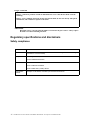
Regulatory specifications and disclaimers
Safety compliance
USA:
UL 60950 - 3rd Edition/CSA 22.2. No. 60950
Canada:
cUL certified - 3rd Edition/CSA 22.2. No. 60950- for Canada (product bears the single
cUL mark for U.S. and Canada)
Europe:
Low Voltage Directive, 73/23/EEC
UL/CB to EN60950 3rd Edition
International:
UL/CB to IEC 60950 3rd Edition
UL/CB - EN60 950 3rd Edition
UL/CB - EMKO-TSE (74-SEC) 207/94
Australia/New
Zealand:
vi
CB Report to IEC 60950, 3rd Edition plus international deviations
Intel Blade Server Fibre Channel Switch Module SBCEFCSW / FC Expansion Card SBFCM Guide
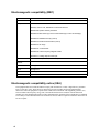
Electromagnetic compatibility (EMC)
USA:
FCC CFR 47 Part 2 and 15, Verified Class A Limit
Canada:
IC ICES-003 Class A Limit
Europe:
EMC Directive, 89/336/EEC
EN55022, Class A Limit, Radiated & Conducted Emissions
EN55024 ITE Specific Immunity Standard
EN61000-4-2 ESD Immunity (Level 2 Contact Discharge, Level 3 Air Discharge)
EN61000-4-3 Radiated Immunity (Level 2)
EN61000-4-4 Electrical Fast Transient (Level 2)
EN61000-4-5 AC Surge
EN61000-4-6 Conducted RF
EN61000-4-8 Power Frequency Magnetic Fields
EN61000-4-11 Voltage Dips and Interrupts
Japan:
VCCI Class A ITE (CISPR 22, Class A Limit)
Australia/New
Zealand:
AS/NZS 3548, Class A Limit
Taiwan:
BSMI Approval
Korea:
RRL Approval
Russia:
GOST Approval
International:
CISPR 22, Class A Limit
Electromagnetic compatibility notice (USA)
This equipment has been tested and found to comply with the limits for a Class A digital device, puruant to
Part 15 of the FCC rules. These limits are designed to provide reasonable protection against harmful
interference when the equipment is operated in a commercial environment. This equipment generates, uses,
and can radiate radio frequency energy and, if not installed and used in accordance with the instruction
manual, may cause harmful interference to radio communications. Operation of this equipment in a residential
area is likely to cause harmful interference in which case the user will be required to correct the interference at
his own expense.
vii
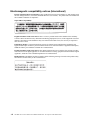
Electromagnetic compatibility notices (International)
Europe (CE Declaration of Conformity): This product has been tested in accordance to, and complies with
the Low Voltage Directive (73/23/EEC) and EMC Directive (89/336/EEC). The product has been marked with
the CE Mark to illustrate its compliance.
Japan EMC Compatibility:
English translation of the notice above: This is a Class A product based on the standard of the Voluntary
Control Council for Interference by Information Technology Equipment (VCCI). If this equipment is used in a
domestic environment, radio disturbance may arise. When such trouble occurs, the user may be required to
take corrective actions.
ICES-003 (Canada): Cet appareil numérique respecte les limites bruits radioélectriques applicables aux
appareils numériques de Classe A prescrites dans la norme sur le matériel brouilleur: "Appareils Numériques",
NBM-003 édictée par le Ministre Canadian des Communications.
English translation of the notice above: This digital apparatus does not exceed the Class A limits for radio
noise emissions from digital apparatus set out in the interference-causing equipment standard entitled "Digital
Apparatus", ICES-003 of the Canadian Department of Communications.
BSMI (Taiwan): The BSMI Certification number and the following warning is located on the product safety
label which is located visibly on the external chassis.
viii
Intel Blade Server Fibre Channel Switch Module SBCEFCSW / FC Expansion Card SBFCM Guide
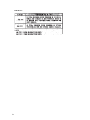
RRL Korea:
ix
English translation of the previous notice:
Device
Class A device
User’s Information
This device complies with RRL EMC and is operated
in commercial environment so that distributors or
users pay attention to this point.
If the product is sold or purchased improperly, please
exchange this product to what can be used at home.
Class B device
This device complies with RRL EMC and is operated
in a residential area so that it can be used at all other
location as well as residential area.
Remarks: Class A device - operated in a commercial area. Class B device - operated in a residential area.
x
Intel Blade Server Fibre Channel Switch Module SBCEFCSW / FC Expansion Card SBFCM Guide
Contents
Safety and regulatory information . . . . . . . . . . . . . . . . . . . . . . . . . . . . . . . . . . . . . . . . . . . . . iii
General Safety . . . . . . . . . . . . . . . . . . . . . . . . . . . . . . . . . . . . . . . . . . . . . . . . . . . . . . . . . . . iv
Electrical Safety . . . . . . . . . . . . . . . . . . . . . . . . . . . . . . . . . . . . . . . . . . . . . . . . . . . . . . . . . . iv
Handling electrostatic discharge-sensitive devices . . . . . . . . . . . . . . . . . . . . . . . . . . . . . . . . v
Regulatory specifications and disclaimers . . . . . . . . . . . . . . . . . . . . . . . . . . . . . . . . . . . . . . vi
Safety compliance . . . . . . . . . . . . . . . . . . . . . . . . . . . . . . . . . . . . . . . . . . . . . . . . . . . . vi
Electromagnetic compatibility (EMC) . . . . . . . . . . . . . . . . . . . . . . . . . . . . . . . . . . . . . vii
Electromagnetic compatibility notice (USA) . . . . . . . . . . . . . . . . . . . . . . . . . . . . . . . . vii
Electromagnetic compatibility notices (International) . . . . . . . . . . . . . . . . . . . . . . . . . viii
1 General information. . . . . . . . . . . . . . . . . . . . . . . . . . . . . . . . . . . . . . . . . . . . . . . . . . . . . . . . 1
Related publications. . . . . . . . . . . . . . . . . . . . . . . . . . . . . . . . . . . . . . . . . . . . . . . . . . . . . . . . 1
Notices used in this book . . . . . . . . . . . . . . . . . . . . . . . . . . . . . . . . . . . . . . . . . . . . . . . . . . . . 2
2 Intel® Blade Server Fibre Channel Switch Module SBCEFCSW . . . . . . . . . . . . . . . . . . . . 3
Command line interface (CLI) . . . . . . . . . . . . . . . . . . . . . . . . . . . . . . . . . . . . . . . . . . . . . . . . 4
Logging on to a switch. . . . . . . . . . . . . . . . . . . . . . . . . . . . . . . . . . . . . . . . . . . . . . . . . . 4
Command syntax . . . . . . . . . . . . . . . . . . . . . . . . . . . . . . . . . . . . . . . . . . . . . . . . . . . . . 5
Commands . . . . . . . . . . . . . . . . . . . . . . . . . . . . . . . . . . . . . . . . . . . . . . . . . . . . . . . . . . 5
Admin command . . . . . . . . . . . . . . . . . . . . . . . . . . . . . . . . . . . . . . . . . . . . . . . . . 7
Alias command. . . . . . . . . . . . . . . . . . . . . . . . . . . . . . . . . . . . . . . . . . . . . . . . . . . 8
Config command . . . . . . . . . . . . . . . . . . . . . . . . . . . . . . . . . . . . . . . . . . . . . . . . 10
Date command . . . . . . . . . . . . . . . . . . . . . . . . . . . . . . . . . . . . . . . . . . . . . . . . . . 12
Fallback command . . . . . . . . . . . . . . . . . . . . . . . . . . . . . . . . . . . . . . . . . . . . . . . 13
Help command . . . . . . . . . . . . . . . . . . . . . . . . . . . . . . . . . . . . . . . . . . . . . . . . . . 14
History command . . . . . . . . . . . . . . . . . . . . . . . . . . . . . . . . . . . . . . . . . . . . . . . . 15
Image command. . . . . . . . . . . . . . . . . . . . . . . . . . . . . . . . . . . . . . . . . . . . . . . . . 16
Lip command (for external ports only) . . . . . . . . . . . . . . . . . . . . . . . . . . . . . . . . 17
Passwd command . . . . . . . . . . . . . . . . . . . . . . . . . . . . . . . . . . . . . . . . . . . . . . . 18
Ps command . . . . . . . . . . . . . . . . . . . . . . . . . . . . . . . . . . . . . . . . . . . . . . . . . . . 19
Quit command . . . . . . . . . . . . . . . . . . . . . . . . . . . . . . . . . . . . . . . . . . . . . . . . . . 20
Reset command . . . . . . . . . . . . . . . . . . . . . . . . . . . . . . . . . . . . . . . . . . . . . . . . . 20
Set command . . . . . . . . . . . . . . . . . . . . . . . . . . . . . . . . . . . . . . . . . . . . . . . . . . . 24
Set Config command . . . . . . . . . . . . . . . . . . . . . . . . . . . . . . . . . . . . . . . . . . . . . 26
Set Log command . . . . . . . . . . . . . . . . . . . . . . . . . . . . . . . . . . . . . . . . . . . . . . . 32
Set Port command . . . . . . . . . . . . . . . . . . . . . . . . . . . . . . . . . . . . . . . . . . . . . . . 34
Set Setup command. . . . . . . . . . . . . . . . . . . . . . . . . . . . . . . . . . . . . . . . . . . . . . 35
Show command . . . . . . . . . . . . . . . . . . . . . . . . . . . . . . . . . . . . . . . . . . . . . . . . . 38
Show Config command . . . . . . . . . . . . . . . . . . . . . . . . . . . . . . . . . . . . . . . . . . . 45
Show Log command. . . . . . . . . . . . . . . . . . . . . . . . . . . . . . . . . . . . . . . . . . . . . . 48
Show Perf command . . . . . . . . . . . . . . . . . . . . . . . . . . . . . . . . . . . . . . . . . . . . . 50
Show Setup command . . . . . . . . . . . . . . . . . . . . . . . . . . . . . . . . . . . . . . . . . . . . 52
Shutdown command. . . . . . . . . . . . . . . . . . . . . . . . . . . . . . . . . . . . . . . . . . . . . . 54
Test command . . . . . . . . . . . . . . . . . . . . . . . . . . . . . . . . . . . . . . . . . . . . . . . . . . 55
Uptime command . . . . . . . . . . . . . . . . . . . . . . . . . . . . . . . . . . . . . . . . . . . . . . . . 57
User command . . . . . . . . . . . . . . . . . . . . . . . . . . . . . . . . . . . . . . . . . . . . . . . . . . 58
Whoami command . . . . . . . . . . . . . . . . . . . . . . . . . . . . . . . . . . . . . . . . . . . . . . . 60
Zone command . . . . . . . . . . . . . . . . . . . . . . . . . . . . . . . . . . . . . . . . . . . . . . . . . 61
Zoneset command . . . . . . . . . . . . . . . . . . . . . . . . . . . . . . . . . . . . . . . . . . . . . . . 64
xi
Zoning command . . . . . . . . . . . . . . . . . . . . . . . . . . . . . . . . . . . . . . . . . . . . . . . . 66
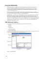
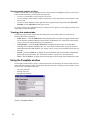
Using the SAN Utility . . . . . . . . . . . . . . . . . . . . . . . . . . . . . . . . . . . . . . . . . . . . . . . . . . . . . . 69
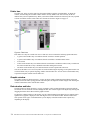
SAN Utility user interface . . . . . . . . . . . . . . . . . . . . . . . . . . . . . . . . . . . . . . . . . . . . . . 69
Menu bar . . . . . . . . . . . . . . . . . . . . . . . . . . . . . . . . . . . . . . . . . . . . . . . . . . . . . . 70
Toolbar . . . . . . . . . . . . . . . . . . . . . . . . . . . . . . . . . . . . . . . . . . . . . . . . . . . . . . . . 71
Fabric tree . . . . . . . . . . . . . . . . . . . . . . . . . . . . . . . . . . . . . . . . . . . . . . . . . . . . . 72
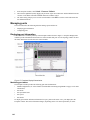
Graphic window . . . . . . . . . . . . . . . . . . . . . . . . . . . . . . . . . . . . . . . . . . . . . . . . . 72
Data window and tabs . . . . . . . . . . . . . . . . . . . . . . . . . . . . . . . . . . . . . . . . . . . . 72
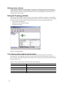
Working status indicator . . . . . . . . . . . . . . . . . . . . . . . . . . . . . . . . . . . . . . . . . . . 73
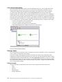
Using the Topology window. . . . . . . . . . . . . . . . . . . . . . . . . . . . . . . . . . . . . . . . . . . . . 73
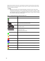
Fibre Channel switch module and link status . . . . . . . . . . . . . . . . . . . . . . . . . . . 73
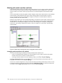
Working with switch modules and links . . . . . . . . . . . . . . . . . . . . . . . . . . . . . . . 74
Topology data window tabs . . . . . . . . . . . . . . . . . . . . . . . . . . . . . . . . . . . . . . . . 75
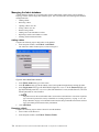
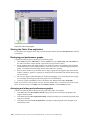
Using the Faceplate window . . . . . . . . . . . . . . . . . . . . . . . . . . . . . . . . . . . . . . . . . . . . 75
Opening the Faceplate window and pop-up menus . . . . . . . . . . . . . . . . . . . . . . 76
Port views and status . . . . . . . . . . . . . . . . . . . . . . . . . . . . . . . . . . . . . . . . . . . . . 76
Working with ports . . . . . . . . . . . . . . . . . . . . . . . . . . . . . . . . . . . . . . . . . . . . . . . 76
Faceplate data window tabs . . . . . . . . . . . . . . . . . . . . . . . . . . . . . . . . . . . . . . . . 77
Managing fabrics . . . . . . . . . . . . . . . . . . . . . . . . . . . . . . . . . . . . . . . . . . . . . . . . . . . . . 77
Setting up security . . . . . . . . . . . . . . . . . . . . . . . . . . . . . . . . . . . . . . . . . . . . . . . 77
Managing the fabric database . . . . . . . . . . . . . . . . . . . . . . . . . . . . . . . . . . . . . . 78
Displaying fabric information . . . . . . . . . . . . . . . . . . . . . . . . . . . . . . . . . . . . . . . 80
Zoning a fabric . . . . . . . . . . . . . . . . . . . . . . . . . . . . . . . . . . . . . . . . . . . . . . . . . . 82
Using the Zoning Config window . . . . . . . . . . . . . . . . . . . . . . . . . . . . . . . . . . . . 85
Restoring default zoning. . . . . . . . . . . . . . . . . . . . . . . . . . . . . . . . . . . . . . . . . . . 85
Merging fabrics and zoning . . . . . . . . . . . . . . . . . . . . . . . . . . . . . . . . . . . . . . . . 85
Using the Edit Zoning window . . . . . . . . . . . . . . . . . . . . . . . . . . . . . . . . . . . . . . 86
Managing zone sets . . . . . . . . . . . . . . . . . . . . . . . . . . . . . . . . . . . . . . . . . . . . . . 87
Managing zones . . . . . . . . . . . . . . . . . . . . . . . . . . . . . . . . . . . . . . . . . . . . . . . . . 89
Managing aliases . . . . . . . . . . . . . . . . . . . . . . . . . . . . . . . . . . . . . . . . . . . . . . . . 91
Managing switch modules . . . . . . . . . . . . . . . . . . . . . . . . . . . . . . . . . . . . . . . . . . . . . . 92
Displaying switch module information . . . . . . . . . . . . . . . . . . . . . . . . . . . . . . . . 92
Managing alarms . . . . . . . . . . . . . . . . . . . . . . . . . . . . . . . . . . . . . . . . . . . . . . . . 97
Exporting name server information to a file . . . . . . . . . . . . . . . . . . . . . . . . . . . . 98
Paging a switch module . . . . . . . . . . . . . . . . . . . . . . . . . . . . . . . . . . . . . . . . . . . 98
Setting the date and time . . . . . . . . . . . . . . . . . . . . . . . . . . . . . . . . . . . . . . . . . . 98
Resetting a switch module . . . . . . . . . . . . . . . . . . . . . . . . . . . . . . . . . . . . . . . . . 98
Configuring a switch module . . . . . . . . . . . . . . . . . . . . . . . . . . . . . . . . . . . . . . . 98
Network properties . . . . . . . . . . . . . . . . . . . . . . . . . . . . . . . . . . . . . . . . . . . . . . 100
Archiving a switch module . . . . . . . . . . . . . . . . . . . . . . . . . . . . . . . . . . . . . . . . 102
Managing firmware. . . . . . . . . . . . . . . . . . . . . . . . . . . . . . . . . . . . . . . . . . . . . . 102
Managing ports . . . . . . . . . . . . . . . . . . . . . . . . . . . . . . . . . . . . . . . . . . . . . . . . . . . . . 103
Displaying port information. . . . . . . . . . . . . . . . . . . . . . . . . . . . . . . . . . . . . . . . 103
Configuring ports . . . . . . . . . . . . . . . . . . . . . . . . . . . . . . . . . . . . . . . . . . . . . . . 108
Switch management utility functions . . . . . . . . . . . . . . . . . . . . . . . . . . . . . . . . . . . . . . . . . 114
LED diagnostics . . . . . . . . . . . . . . . . . . . . . . . . . . . . . . . . . . . . . . . . . . . . . . . . . . . . 114
Heartbeat LED patterns . . . . . . . . . . . . . . . . . . . . . . . . . . . . . . . . . . . . . . . . . . 115
Switch module fault LED flash pattern . . . . . . . . . . . . . . . . . . . . . . . . . . . . . . . 116
Switch module OK LED . . . . . . . . . . . . . . . . . . . . . . . . . . . . . . . . . . . . . . . . . . 116
Port logged-in LED flash patterns . . . . . . . . . . . . . . . . . . . . . . . . . . . . . . . . . . 116
Port fault LED flash patterns . . . . . . . . . . . . . . . . . . . . . . . . . . . . . . . . . . . . . . 117
Port testing . . . . . . . . . . . . . . . . . . . . . . . . . . . . . . . . . . . . . . . . . . . . . . . . . . . . . . . . 117
xii
Intel Blade Server Fibre Channel Switch Module SBCEFCSW / FC Expansion Card SBFCM Guide
Fibre Channel switch module monitoring using SNMP . . . . . . . . . . . . . . . . . . . . . . .
SNMP configuration . . . . . . . . . . . . . . . . . . . . . . . . . . . . . . . . . . . . . . . . . . . . .
SNMP trap configuration . . . . . . . . . . . . . . . . . . . . . . . . . . . . . . . . . . . . . . . . .
Restoring Fibre Channel switch module configuration . . . . . . . . . . . . . . . . . . . . . . .
Configuration backup . . . . . . . . . . . . . . . . . . . . . . . . . . . . . . . . . . . . . . . . . . . .
Configuration restore . . . . . . . . . . . . . . . . . . . . . . . . . . . . . . . . . . . . . . . . . . . .
Restoring the factory default configuration. . . . . . . . . . . . . . . . . . . . . . . . . . . .
Reinitializing the configuration file system . . . . . . . . . . . . . . . . . . . . . . . . . . . .
Restoring a switch module . . . . . . . . . . . . . . . . . . . . . . . . . . . . . . . . . . . . . . . .
Using the Fabric View application . . . . . . . . . . . . . . . . . . . . . . . . . . . . . . . . . . . . . . .
Starting the Fabric View application . . . . . . . . . . . . . . . . . . . . . . . . . . . . . . . . .
Displaying port performance graphs . . . . . . . . . . . . . . . . . . . . . . . . . . . . . . . .
Arranging and sizing port performance graphs . . . . . . . . . . . . . . . . . . . . . . . .
Customizing port performance graphs . . . . . . . . . . . . . . . . . . . . . . . . . . . . . . .
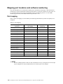
Mapping port locations and software numbering . . . . . . . . . . . . . . . . . . . . . . . . . . . . . . . .
Port mapping. . . . . . . . . . . . . . . . . . . . . . . . . . . . . . . . . . . . . . . . . . . . . . . . . . . . . . .
118
118
119
119
120
120
120
121
121
121
122
122
122
123
124
124
3 Intel® Server FC Expansion Card SBFCM . . . . . . . . . . . . . . . . . . . . . . . . . . . . . . . . . . . .
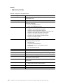
Features and specifications . . . . . . . . . . . . . . . . . . . . . . . . . . . . . . . . . . . . . . . . . . . . . . . .
Inventory checklist . . . . . . . . . . . . . . . . . . . . . . . . . . . . . . . . . . . . . . . . . . . . . . . . . . . . . . .
Notices and statements used in this book . . . . . . . . . . . . . . . . . . . . . . . . . . . . . . . . . . . . .
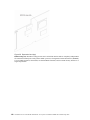
Major components of the SBFCM Expansion Card . . . . . . . . . . . . . . . . . . . . . . . . . . . . . .
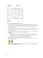
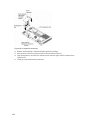
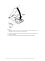
Installing the Expansion Card . . . . . . . . . . . . . . . . . . . . . . . . . . . . . . . . . . . . . . . . . . . . . .
Installation guidelines . . . . . . . . . . . . . . . . . . . . . . . . . . . . . . . . . . . . . . . . . . . . . . . .
Handling static-sensitive devices . . . . . . . . . . . . . . . . . . . . . . . . . . . . . . . . . . .
Installing the Expansion Card . . . . . . . . . . . . . . . . . . . . . . . . . . . . . . . . . . . . . . . . . .
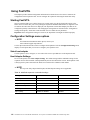
Using Fast!UTIL . . . . . . . . . . . . . . . . . . . . . . . . . . . . . . . . . . . . . . . . . . . . . . . . . . . . . . . .
Starting Fast!UTIL . . . . . . . . . . . . . . . . . . . . . . . . . . . . . . . . . . . . . . . . . . . . . . . . . . .
Configuration Settings menu options . . . . . . . . . . . . . . . . . . . . . . . . . . . . . . . . . . . .
Select host adapter . . . . . . . . . . . . . . . . . . . . . . . . . . . . . . . . . . . . . . . . . . . . .
Host Adapter Settings . . . . . . . . . . . . . . . . . . . . . . . . . . . . . . . . . . . . . . . . . . .
Selectable Boot Settings . . . . . . . . . . . . . . . . . . . . . . . . . . . . . . . . . . . . . . . . .
Restore Default Settings . . . . . . . . . . . . . . . . . . . . . . . . . . . . . . . . . . . . . . . . .
Raw NOVRAM data . . . . . . . . . . . . . . . . . . . . . . . . . . . . . . . . . . . . . . . . . . . . .
Advanced Adapter Settings . . . . . . . . . . . . . . . . . . . . . . . . . . . . . . . . . . . . . . .
Extended Firmware Settings . . . . . . . . . . . . . . . . . . . . . . . . . . . . . . . . . . . . . .
Scan Fibre Channel devices . . . . . . . . . . . . . . . . . . . . . . . . . . . . . . . . . . . . . .
Fibre Channel disk utility . . . . . . . . . . . . . . . . . . . . . . . . . . . . . . . . . . . . . . . . .
Loopback data test . . . . . . . . . . . . . . . . . . . . . . . . . . . . . . . . . . . . . . . . . . . . . .
ExitFast!UTIL . . . . . . . . . . . . . . . . . . . . . . . . . . . . . . . . . . . . . . . . . . . . . . . . . .
125
125
127
127
127
129
129
130
130
136
136
136
136
136
137
137
138
138
139
140
140
140
140
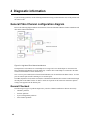
4 Diagnostic information . . . . . . . . . . . . . . . . . . . . . . . . . . . . . . . . . . . . . . . . . . . . . . . . . . .
General Fibre Channel configuration diagram . . . . . . . . . . . . . . . . . . . . . . . . . . . . . . . . . .
General Checkout . . . . . . . . . . . . . . . . . . . . . . . . . . . . . . . . . . . . . . . . . . . . . . . . . . .
Hardware problems . . . . . . . . . . . . . . . . . . . . . . . . . . . . . . . . . . . . . . . . . . . . .
Software problems . . . . . . . . . . . . . . . . . . . . . . . . . . . . . . . . . . . . . . . . . . . . . .
System configuration problems . . . . . . . . . . . . . . . . . . . . . . . . . . . . . . . . . . . .
Fibre channel problems . . . . . . . . . . . . . . . . . . . . . . . . . . . . . . . . . . . . . . . . . .
141
141
141
142
142
142
143
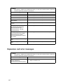
5 Symptom-to-FRU index . . . . . . . . . . . . . . . . . . . . . . . . . . . . . . . . . . . . . . . . . . . . . . . . . . .
Fast!UTIL utility status codes . . . . . . . . . . . . . . . . . . . . . . . . . . . . . . . . . . . . . . . . . . . . . . .
Switch error messages . . . . . . . . . . . . . . . . . . . . . . . . . . . . . . . . . . . . . . . . . . . . . . . . . . .
Expansion card error messages . . . . . . . . . . . . . . . . . . . . . . . . . . . . . . . . . . . . . . . . . . . .
145
146
146
147
Contents
xiii
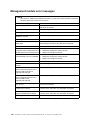
Management module error messages . . . . . . . . . . . . . . . . . . . . . . . . . . . . . . . . . . . . . . . .
Switch diagnostic information . . . . . . . . . . . . . . . . . . . . . . . . . . . . . . . . . . . . . . . . . . . . . .
LED error codes . . . . . . . . . . . . . . . . . . . . . . . . . . . . . . . . . . . . . . . . . . . . . . . . . . . .
I2C diagnostic register definitions . . . . . . . . . . . . . . . . . . . . . . . . . . . . . . . . . . . . . . .
Undetermined problems. . . . . . . . . . . . . . . . . . . . . . . . . . . . . . . . . . . . . . . . . . . . . . . . . . .
Problem determination tips . . . . . . . . . . . . . . . . . . . . . . . . . . . . . . . . . . . . . . . . . . . . . . . .
148
149
149
149
150
151
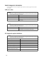
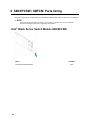
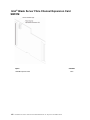
6 SBCEFCSW / SBFCM Parts listing . . . . . . . . . . . . . . . . . . . . . . . . . . . . . . . . . . . . . . . . . 153
Intel® Blade Server Switch Module SBCEFCSW . . . . . . . . . . . . . . . . . . . . . . . . . . . . . . . 153
Intel® Blade Server Fibre Channel Expansion Card SBFCM . . . . . . . . . . . . . . . . . . . . . . 154
A Getting help and technical assistance . . . . . . . . . . . . . . . . . . . . . . . . . . . . . . . . . . . . . . 155
Before you call . . . . . . . . . . . . . . . . . . . . . . . . . . . . . . . . . . . . . . . . . . . . . . . . . . . . . . . . . . 155
Using the documentation . . . . . . . . . . . . . . . . . . . . . . . . . . . . . . . . . . . . . . . . . . . . . . . . . . 155
xiv
Intel Blade Server Fibre Channel Switch Module SBCEFCSW / FC Expansion Card SBFCM Guide
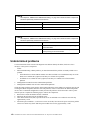
1 General information
Fibre Channel technology is outlined in the SCSI-3 Fibre Channel Protocol (SCSI-FCP) standard. Fibre
Channel is a high-speed data transport technology used for mass storage and networking.
By adding Fibre Channel Expansion Cards to the blade servers and Fibre Channel switch modules to the Intel®
Blade Server Chassis SBCE, you can attach the blade server to an external storage area network (SAN)
through the external 2 Gbps (gigabits per second) optical ports on the switch modules. The Fibre Channel
Expansion Card supports data-transfer rates up to 200 MB per second half-duplex and 400 MB per second
full-duplex.
Related publications
This Hardware Maintenance and Troubleshooting Guide contains information to help you slve problems
yourself or to provide helpful information to a service technician. In addition to this guide, the following
related documentation is provided with your switch module:
•
Intel® Blade Server Switch Module SBCEFCSW Management and User’s Guide
This publication is provided in Portable Document Format (PDF) on the Intel® Blade Server Switch
Module SBCEFCSW Reource CD. It describes how to use the SAN Utility application, describes how to
start the Telnet CLI, and lists the CLI commands and their usage.
1
•
Intel® Blade Server Chassis SBEFCSW Installation Guide
This publication is provided in Portable Document Format (PDF) on the Resource CD. It contains
installation and setup instructions for your switch module. It also provides general information about your
switch module, including getting started, configuring your switch module, and how to access and use online help.
•
Intel® Blade Server Compute Switch Module SBCFM Installation and User’s Guide
This publication is provided in PDF on the Resource CD. It contains instructions for installing the Intel
Fibre Channel Expansion card into an Intel Blade Server Compute. This publication contains information
about
— Installing and configuring the expansion card
— Updating the BIOS and device drivers of the expansion card
•
QLogic® SAN Solutions Guide
This publication is provided in PDF on the Resource CD. It provides a user-oriented discussion of how
Fibre Channel options are used to provide different SAN storage solutions for various application
requirements. This document also provides an overview and description for backup and restore, business
continuance and high availability, and storage consolidation and data sharing solutions.
•
QLogic® Switch Interoperability Guide
This publication is provided in PDF on the Resource CD. It provides detailed Fibre Channel switch
configuration data and step-by-step configuration procedures for integrating the Blade Server Chassis
SBCE into other vendor switch fabrics. Each vendor configuration includes:
— An initial integration checklist
— Configuration limitations
— Supported switch and firmware versions
— Specific management application operations
— A successful-integration checklist.
•
QLogic® SAN Interoperability Guide
This publication is provided in PDF on the Resource CD. It is a key resource for SAN planning and
implementation. It provides interoperability matrices that let you identify at a glance the certified SAN
products, solutions, and services that best suit your needs.
•
QLogic® SAN Configuration Guide: CLARiiON Storage
This publication is provided in PDF on the Resource CD. It is a comprehensive guide for those interested
in deploying QLogic and CLARiion Storage solutions.
•
QLogic® SAN Configuration Guide: LSI Storage
This publication is provided in PDF on the Resource CD. It is a comprehensive guide for those interested
in deploying QLogic and LSI Storage solutions.
•
QLogic® SAN Configuration Guide: XIOtech Storage
This publication is provided in PDF on the Resource CD. It is a comprehensive guide for those interested
in deploying QLogic and XIOtech Storage solutions.
•
Intel® Server Boards and Server Chassis Safety Information
This multilingual publication is provided in PDF on the Resource CD. It contains translated versions of
the caution and danger statements that appear in the documentation.
Notices used in this book
The following notices are used in this book:
• Notes: These notices provide important tips, guidance, or advice.
• Important: These notices provide information or advice that might help you avoid inconvenient or
problem situations.
• Attention: These notices indicate potential damage to programs, devices, or data. An attention notice is
placed just before the instruction or situation in which damage could occur.
2
Intel Blade Swerver Switch Module SBCEFCSW / FC Expansion Card SBFCM: HMM and Troubleshooting Guide
2 Intel® Blade Server Fibre Channel Switch
Module SBCEFCSW
✏ NOTE
Throughout this publication, the phrases "switch module" and "fibre channel switch module" refer
to the Intel® Blade Server Fibre Channel Switch Module SBCEFCSW.
You can manage and configure your Intel® Blade Server Fibre Channel Switch Module SBCEFCSW through a
Telnet connection to the embedded command line interface (CLI) or by using the SAN Utility application. The
SAN Utility provides an intuitive graphical user interface (GUI) that you can use to configure multiple fibre
channel switch modules through other connected SAN devices from a single interface. The SAN Utility
application is referred to throughout this publication as the SAN Utility.
This guide provides instructions to:
• Configure your switch module
• Manage fabrics, ports, and switch modules
• Use Telnet and the CLI to configure switch module parameters
You can manage the SBCE fabric through an Ethernet network using the SAN Utility or the CLI. The SAN
Utility is installed on a Microsoft* Windows* 2003, Red Hat* Linux* Advanced Server Version 2.1 or Red
Hat Linux Version 9.0.
The switch module has an embedded Telnet server through which a Telnet client can connect and manage the
switch module using the CLI. See “Command line interface (CLI)” below for more information about Telnet
and CLI commands.
SNMP provides monitoring and trap functions for the fabric. The switch module firmware supports SNMP
Versions 1, 2, and 3; the Fibre Alliance Management Information Base (FA-MIB) version 4.0; and the Fabric
Element Management Information Base (FE-MIB) RFC 2837. Traps are formatted using SNMP version 2.
If you are an experienced user, you can use the Telnet CLI to perform the following tasks:
• Manage the switch module from the SBCE management module interface to the Telnet client
• Perform single switch management
• Use advanced control commands
If you are a new user or if you need to manage multiple switch modules from a single interface, you can use
the SAN Utility GUI to perform the following tasks:
• Manage your switch module from a remote client or network management workstation
• Manage your multiswitch fabric
For information about installing the switch module and the SAN Utility, see the Switch Module Installation
Guide that comes with the switch module.
3
Command line interface (CLI)
Your switch module contains an embedded Telnet server. This server enables a Telnet client to establish a
Telnet session with the switch module to retrieve information or to configure parameters using the CLI. You
can use the CLI to perform a variety of fabric and switch management tasks through an Ethernet connection to
your Intel® Blade Server Chassis SBCE.
You can access the Telnet interface in two ways:
• In the Blade Server Chassis SBCE management module Web interface
• In a command-line window on a connected network management workstation
Important: Before you configure your switch module, be sure that the management modules in your Blade
Server Chassis SBCE are properly configured. In addition, to access and manage your switch module from an
external environment, you might need to enable certain features, such as the external ports and external
management over all ports. See the applicable SBCE Installation and User’s Guide publications on the
Resource CD for more information. For more detailed information about configuring your switch module, see
the Fibre Channel Switch Module Installation Guide on the Resource CD.
Logging on to a switch
To log on to a switch using Telnet, complete the following steps:
1. Open a command-line window on the network management workstation, type one of the following
commands, and press Enter.
For switch module bay 3:
telnet 192.168.70.129
For switch module bay 4:
telnet 192.168.70.130
2.
A command prompt window opens.
At the Login prompt, type the initial default user ID, USERID. At the Password prompt, type the initial
default password, PASSW0RD (the sixth character is a zero, not the letter O). The user ID and password
are case sensitive.
This user account provides full access to the switch and its configuration. After planning your fabric
management needs and creating your own user accounts, consider changing the password for this account. See
“Commands” for more information about authority levels. See the “User command” on page 58 for
information about creating user accounts.
✏ NOTE
The switch module supports a combined maximum of 15 logins. This includes the SAN Utility inband and out-of-band logins, Telnet out-of-band logins, and SNMP out-of-band logins. A maximum
of ten SAN Utility logins are accepted. Additional logins will be refused.
4
Intel Blade Server Fibre Channel Switch Module SBCEFCSW / FC Expansion Card SBFCM Guide
Command syntax
The command syntax is as follows:
command
keyword
keyword [value]
keyword [value1] [value2]
The command is followed by one or more keywords. Consider the following rules and conventions:
• Commands and keywords are lowercase and case sensitive.
• Required keyword values are shown in standard font: [value]. Optional values are shown in italics:
[value].
• The underlined portion of each keyword indicates the abbreviated form that can be used. For example the
Delete keyword can be abbreviated Del.
Commands
The command set provides for User and Admin authority levels.
• User authority grants viewing access to the fabric and switches using the Show command and other readonly commands.
• Admin authority includes the User authority and grants permission to use the Admin command. The
Admin Start command opens an admin session, which provides access to the commands that change
switch and fabric configurations. See the “Admin command” on page 7.
✏ NOTE
Admin authority is enforced only if fabric security is enabled on the switch. By default, fabric
security is disabled. See the keywords of the “Set Setup command” on page 35 for information
about setting fabric security.
The commands and their page numbers are listed by authority level in Table 1. The following Admin session
commands have some keywords that are available with User authority:
Alias
Config
Date
Set
User
Zone
Zoneset
Zoning
5
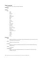
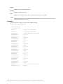
Table 1. Commands listed by authority level
User authority commands
Help
“Help command” on page 14.
History
“History command” on page 15.
Ps
“Ps command” on page 19.
Quit
“Quit command” on page 20.
Show
“Show command” on page 38.
Show Config
“Show Config command” on page
45.
Show Log
“Show Log command” on page 48.
Show Perf
“Show Perf command” on page 50.
Show Setup
“Show Setup command” on page
52.
Uptime
“Uptime command” on page 57.
Whoami
6
“Whoami command” on page 60
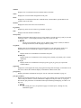
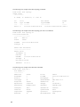
Admin authority command
Admin
“Admin command” on page 7
Admin session commands
Alias
“Alias command” on page 8.
Config
“Config command” on page 10.
Date
“Date command” on page 12.
Fallback
“Fallback command” on page 13.
Image
“Image command” on page 16.
Lip
“Lip command (for external ports
only)” on page 17.
Passwd
“Passwd command” on page 18.
Reset
“Reset command” on page 20.
Set
“Set command” on page 24.
Set Config
“Set Config command” on page 26.
Set Log
“Set Log command” on page 32.
Set Port
“Set Port command” on page 34.
Set Setup
“Set Setup command” on page 35.
Shutdown
“Shutdown command” on page 54.
Test
“Test command” on page 55.
User
“User command” on page 58.
Zone
“Zone command” on page 61.
Zoneset
“Zoneset command” on page 64.
Zoning
“Zoning command” on page 66
Intel Blade Server Fibre Channel Switch Module SBCEFCSW / FC Expansion Card SBFCM Guide
Admin command
Opens and closes an admin session. The admin session provides commands that change the fabric and switch
configurations. Only one admin session can be open on the switch at any time. An inactive admin session will
time out after a period of time that can be changed using the Set Setup System command. See the “Set Setup
command” on page 35.
Authority
Admin
Syntax
admin
start
end
cancel
Keywords
start
Opens the admin session.
end
Closes the admin session. The Logout, Shutdown, and Reset Switch commands will also end an
admin session.
cancel
Terminates an admin session opened by another user. Use this keyword with care because it
terminates the admin session without warning the other user and without saving pending changes.
Notes
Closing a Telnet window during an admin session does not release the session. In this case, you must either
wait for the admin session to time out, or use the Admin Cancel command.
Examples
The following example shows how to open and close an admin session.
FCSM: user1> admin start
FCSM: (admin) user1>
.
.
.
FCSM (admin): user1> admin end
FCSM: user1>
7
Alias command
Creates a named set of ports. Aliases make it easier to assign a set of ports to many zones. An alias cannot have
a zone or another alias as a member.
Authority
Admin
Syntax
alias
add [alias] [members]
copy [alias_source] [alias_destination]
create [alias]
delete [alias]
list
members [alias]
remove [alias] [members]
rename [alias_old] [alias_new]
Keywords
add [alias] [members]
Specifies one or more ports given by [members] to add to the alias named [alias]. An alias can have a
maximum of 2000 members. [members] can have one of the following formats:
• Domain ID and port number pair (domain ID, port number). Domain IDs and port numbers are in
decimal format. Ports are numbered beginning with 0.
• 6-character hexadecimal device Fibre Channel address (hex)
• 16-character hexadecimal port worldwide name (PWWN) with the format
xx:xx:xx:xx:xx:xx:xx:xx.
The application verifies that the [alias] format is correct but does not validate that such a port exists.
copy [alias_source] [alias_destination]
Creates a new alias named [alias_destination] and copies the membership into it from the alias given
by [alias_source].
create [alias]
Creates an alias with the name given by [alias]. An alias name must begin with a letter and be no
longer than 64 characters. Valid characters are 0-9, A-Z, a-z, &, _, and -. The zoning database
supports a maximum of 256 aliases.
delete alias
Deletes the specified alias given by [alias] from the zoning database. If the alias is a member of the
active zone set, the alias will not be removed from the active zone set until the active zone set is
deactivated.
list
Displays a list of all aliases. This keyword is valid for User authority and does not require a zoning
edit session or an admin session.
members [alias]
Displays all members of the alias given by [alias]. This keyword is available with User authority and
does not require a zoning edit session or an admin session.
8
Intel Blade Server Fibre Channel Switch Module SBCEFCSW / FC Expansion Card SBFCM Guide
remove [alias] [members]
Removes the ports given by [members] from the alias given by [alias]. [members] can have one of the
following formats:
• Domain ID and port number pair (domain ID, port number). Domain IDs and port numbers are in
decimal format. Ports are numbered beginning with 0.
• 6-character hexadecimal device Fibre Channel address (hex)
• 16-character hexadecimal port worldwide name (PWWN) for the device with the format
xx:xx:xx:xx:xx:xx:xx:xx.
rename [alias_old] [alias_new]
Renames the alias given by [alias_old] to the alias given by [alias_new].
9
Config command
Manages the Fibre Channel configurations on a switch. For information about setting the port and switch
configurations, see the “Set Config command” on page 26.
Authority
Admin for all keywords except List
Syntax
config
activate [config]
backup
cancel
copy [config_source] [config_destination]
delete [config]
edit [config]
list
restore
save [config]
Keywords
activate [config]
Activates the configuration given by [config]. If you omit the configuration, the currently active
configuration is used. Only one configuration can be active at a time.
backup
Creates a file named configdata, which contains the configuration information. To download this file,
open a File Transfer Protocol (FTP) session, log in with account name of images and password of
images, and type get configdata.
cancel
Terminates the current configuration edit session without saving changes that were made.
copy [config_source] [config_destination]
Copies the configuration given by [config_source] to the configuration given by [config_destination].
The switch supports up to 10 configurations including the default configuration.
delete [config]
Deletes the specified configuration file where [config] is a file name.
edit [config]
Opens an edit session for the configuration given by [config]. If you omit the configuration name, the
currently active configuration is used.
list
Displays a list of all available configurations. This keyword is available with User authority.
restore
Restores configuration settings to an out-of-band switch from a backup file named configdata, which
must be first uploaded on the switch using FTP. You create the backup file using the Config Backup
command. Use FTP to load the backup file on a switch, and then enter the Config Restore command.
save [config]
Saves changes made during a configuration edit session in the configuration given by [config]. If you
omit the configuration name value, the configuration you chose for the Config Edit command is used.
10
Intel Blade Server Fibre Channel Switch Module SBCEFCSW / FC Expansion Card SBFCM Guide
Notes
If you edit the active configuration, changes will be suspended until you reactivate the configuration or activate
another configuration.
Examples
The following shows an example of how to open and close a Config Edit session.
FCSM: user1> admin start
FCSM (admin) : user1> config edit
.
.
.
FCSM (admin-config) : user1> config cancel
Configuration mode will be canceled.Please confirm (y/n): [n] y
FCSM (admin) : user1> admin end
11
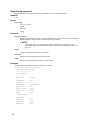
Date command
Displays or sets the blade server date and time. To set the date and time, you must provide the information
string in this format: MMDDhhmmCCYY, where MM = month, DD = day, hh = hour, mm = minute, CC =
century, and YY = year. You must reset the switch for the new date to take effect.
Authority
Admin to change the date; user to display the date.
Syntax
date
[MMDDhhmmCCYY]
Keywords
[MMDDhhmmCCYY]
Specifies the date – this requires an admin session. If you omit [MMDDhhmmCCYY], the current date
is displayed – this is available with User authority.
Examples
The following is an example of the Date command.
FCSM: user1> date
Thu Sep 26 07:51:24 2002
12
Intel Blade Server Fibre Channel Switch Module SBCEFCSW / FC Expansion Card SBFCM Guide
Fallback command
Loads the fallback version of the firmware from switch memory. The switch stores two versions of the
firmware. This command alternately activates the two versions.
Authority
Admin
Syntax
fallback
Notes
•
•
The Show Switch command displays the available firmware versions and the currently active version.
After running the Fallback command, reset the switch for the firmware to be in effect.
Examples
The following is an example of the Fallback command.
FCSM: user1> admin start
FCSM (admin) : user1> fallback
Reverting to previous software image.
FCSM: user1> admin end
FCSM: user1>
13
Please confirm (y/n): [n] y
Help command
Displays a brief description of the specified command and its keywords.
Authority
User
Syntax
help
[command]
[keyword]
Keywords
[command]
A command name. If you omit this value, all available commands from which to choose are
displayed.
[keyword]
A keyword associated with the command named by [command]. If you omit this value, available
keywords for the specified command are displayed.
all
Displays a list of all available commands (including command variations).
Examples
The following is an example of the Help Set command.
FCSM: user1> help set
set SET_OPTIONS
There are many attributes that can be set.
Type help with one of the following to get more information:
set alarm
set beacon
set blade
set config blade
set config port
set config ports
set config switch
set config threshold
set config zoning
set log
set pagebreak
set port
set setup snmp
set setup system
set switch
The following is an example of the Help Set Beacon command.
FCSM: user1> help set beacon
set beacon On | Off
This command allows the lights on the front of the switch to flash.
The On option will start and the Off option will stop the flashing.
14
Intel Blade Server Fibre Channel Switch Module SBCEFCSW / FC Expansion Card SBFCM Guide
History command
Displays a numbered list of the previously entered commands from which you can re-execute selected
commands.
Authority
User
Syntax
history
Notes
Use the History command to provide context for the! command.
• Enter ![command] to re-enter the most recent execution of that command.
• Enter ![line number] to re-execute the corresponding command from the History display
• Enter ![partial command string] to re-execute a command that matches the command string.
• Enter !! to re-execute the most recent command.
Examples
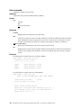
The following is an example of the History command.
FCSM: user1> history
1 show switch
2 date
3 help set
4 history
FCSM: user1> !2
date
Thu Sep 26 11:03:07 2002
15
Image command
Manages and installs switch firmware.
Authority
Admin
Syntax
image
cleanup
fetch [account_name] [ip_address] [file_source] [file_destination]
list
unpack [file]
Keywords
cleanup
Removes all firmware image files from the switch. All firmware image files are removed
automatically each time the switch is reset.
fetch [account_name] [ip_address] [file_source] [file_destination]
Retrieves image file given by [file_source] and stores it on the switch with the file name given by
[file_destination]. The image file is retrieved from the device with the IP address given by
[Ip_address] and an account name given by [account_name]. If an account name needs a password to
access the device, you are prompted for it.
list
Displays the list of image files that reside on the switch.
unpack [file]
Installs the firmware file given by [file]. After unpacking the file, a message appears confirming
successful unpacking. The switch must be reset for the new firmware to take effect.
16
Intel Blade Server Fibre Channel Switch Module SBCEFCSW / FC Expansion Card SBFCM Guide
Lip command (for external ports only)
Reinitializes the specified loop port.
Authority
Admin
Syntax
lip
[port_number]
Keywords
[port_number]
The number of the port to be reinitialized.
Examples
The following is an example of the Lip command.
FCSM (admin) : user1> lip 2
17
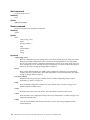
Passwd command
Changes the password for a user account.
Authority
Admin to change the password for another account; user to change your own.
Syntax
passwd
[account_name]
Keywords
[account_name]
The user account name. You must open an admin session to change the password for an account name
other than your own. If you omit [account_name], you are prompted to change the password for the
current account name.
Examples
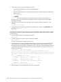
The following is an example of the Passwd command.
FCSM (admin) : user1> passwd user2
Press 'q' and the ENTER key to abort this command.
account OLD password
:
account NEW password (4-20 chars)
:
please confirm account NEW password:
password has been changed.
✏ NOTE
If you lose the password for the account, contact Support (see A, “Getting help and technical
assistance,” on page 155).
18
Intel Blade Server Fibre Channel Switch Module SBCEFCSW / FC Expansion Card SBFCM Guide
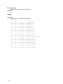
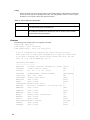
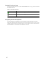
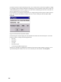
Ps command
Displays current blade server process information.
Authority
User
Syntax
ps
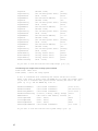
Examples
The following is an example of the Ps command.
FCSM: user1> ps
PID
19
PPID %CPU
TIME
ELAPSED COMMAND
341
329
0.0 00:00:00
2-00:58:29 cns
342
329
0.0 00:00:02
2-00:58:29 ens
343
329
0.0 00:00:27
2-00:58:29 dlog
344
329
1.3 00:40:39
2-00:58:29 ds
345
329
1.4 00:41:38
2-00:58:29 mgmtApp
346
329
0.0 00:00:06
2-00:58:29 fc2
347
329
0.5 00:16:35
2-00:58:29 nserver
348
329
0.4 00:12:20
2-00:58:29 mserver
349
329
3.6 01:47:29
2-00:58:29 util
350
329
0.0 00:00:36
2-00:58:29 snmpservicepath
351
329
0.5 00:15:24
2-00:58:29 eport
352
329
0.0 00:00:05
2-00:58:29 PortApp
361
329
0.0 00:00:08
2-00:58:28 port_mon
362
329
0.2 00:07:14
2-00:58:28 zoning
363
329
0.0 00:00:00
2-00:58:28 diagApp
385
329
0.0 00:00:02
2-00:58:18 snmpd
386
329
0.0 00:00:00
2-00:58:18 snmpmain
Quit command
Closes the Telnet session.
Authority
User
Syntax
quit, exit, or logout
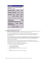
Reset command
Resets the switch and port configuration parameters.
Authority
Admin
Syntax
reset
config [config_name]
factory
port [port_number]
snmp
switch (default)
system
zoning
Keywords
config [config_name]
Resets the configuration given by [config_name] to the factory default values for switch, port, alarm
threshold, and zoning configuration. This keyword clears all zoning definitions. If [config_name]
does not exist on the switch, a configuration with that name is created. If you omit [config_name], the
active configuration is reset. You must activate the configuration or reset the switch for the changes to
take effect. See Table 2 on page 21 through Table 4 on page 22.
factory
Resets switch, alarm threshold, port, SNMP, zoning configuration, and blade server configuration
settings to the factory default values. The switch configuration is activated automatically. See Table 2
on page 21 through Table 6 on page 23.
port [port_number]
Reinitializes the port given by [port_number]. Ports are numbered beginning with 0. For more
information, see Table 37 on page 124.
snmp
Resets the SNMP configuration settings to the factory default values. See Table 5 on page 23 for
SNMP configuration default values.
switch
Reinitializes the switch. This is the default. This command also closes the Telnet session.
system
Resets the blade server configuration settings to the factory default values. See Table 6 on page 23 for
configuration default values.
zoning
Clears the zoning database and deactivates the active zone set. The zoning configuration values
remain unchanged.
20
Intel Blade Server Fibre Channel Switch Module SBCEFCSW / FC Expansion Card SBFCM Guide
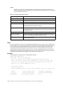
Notes
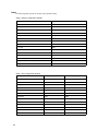
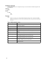
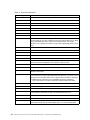
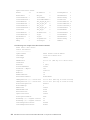
The following tables specify the various factory default settings.
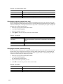
Table 2. Switch configuration defaults
Parameter
Default
Admin State
Online
Broadcast Enabled
True
Inband Enable
True
Domain ID
1
Domain ID Lock
False
Symbolic Name
Fibre Channel Switch Module
R_T_TOV
100
R_A_TOV
10000
E_D_TOV
2000
FS_TOV
5000
DS_TOV
5000
Principal Priority
254
System Description
Fibre Channel Switch Module
Configuration Last Saved By
Initial
Configuration Last Saved On
Initial
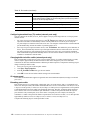
Table 3. Port configuration defaults
Parameter
21
External port (0,15) default
Internal port (1-14) default
Admin State
Online
Online
Link Speed
Auto
2 Gbps
Port Type
GL
F
TL_Port Mode
TLTargetMode
TLTargetMode
ISL Security
Any
Any
Symbolic Name
Port0 or Port15
Port1 – Port14
ALFairness
False
False
ARB_FF
False
False
InteropCredit
0
0
ExtCredit
0
0
FanEnable
True
True
LCFEnable
False
False
MFSEnable
True
True
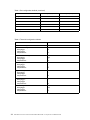
Table 3. Port configuration defaults (continued)
Parameter
External port (0,15) default
Internal port (1-14) default
MFS_TOV
10
10
MSEnable
True
True
NoClose
False
False
IOStreamGuard
False
False
VIEnable
False
False
CheckAlps
False
False
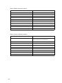
Table 4. Threshold configuration defaults
Parameter
22
Default
ThresholdMonitoringEnabled
True
CRCErrorsMonitoringEnabled
RisingTrigger
FallingTrigger
SampleWindow
True
25
1
10
DecodeErrorsMonitoringEnabled
RisingTrigger
FallingTrigger
SampleWindow
True
200
0
10
ISLMonitoringEnabled
RisingTrigger
FallingTrigger
SampleWindow
True
2
0
10
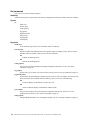
LoginMonitoringEnabled
RisingTrigger
FallingTrigger
SampleWindow
True
5
1
10
LogoutMonitoringEnabled
RisingTrigger
FallingTrigger
SampleWindow
True
5
1
10
LOSMonitoringEnabled
RisingTrigger
FallingTrigger
SampleWindow
True
100
5
10
Intel Blade Server Fibre Channel Switch Module SBCEFCSW / FC Expansion Card SBFCM Guide
Table 5. SNMP configuration defaults
Parameter
Default
Contact
Undefined
Location
Undefined
Description
Undefined
Trap [1] Address
10.0.0.1
Trap [2-5] Address
0.0.0.0
Trap [1-5] Port
162
Trap [1-5] Severity
Warning
Trap [1-5] Enabled
False
ObjectID
1.3.6.1.4.1.1663.1.1.1.1.16
AuthFailureTrap
False
Table 6. System configuration defaults
Parameter
Ethernet Network IP Address
Default
Switch module bay 3: 192.168.70.129
Switch module bay 4: 192.168.70.130
23
Ethernet Network IP Mask
255.255.255.0
Ethernet Gateway Address
10.90.90.254
Ethernet Network Discovery
Static
Admin Timeout
30 minutes
Security Enabled
False
Local Log Enabled
True
Remote Log Enabled
False
Remote Log Host IP Address
10.0.0.254
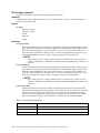
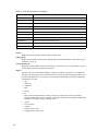
Set command
Sets a variety of port and switch parameters.
Authority
Admin for all keywords except Alarm Clear, Beacon, and Pagebreak which are available with User authority.
Syntax
set
alarm clear
beacon [state]
config [option]
log [option]
pagebreak [state]
port [option]
setup [option]
switch [state]
Keywords
alarm clear
Clears the alarm log. This keyword is available with User authority.
beacon [state]
Enables or disables the flashing of the Port Logged-in LEDs according to [state]. This keyword is
available with User authority. [state] can be one of the following:
On
Enables the flashing beacon.
Off
Disables the flashing beacon.
config [option]
Sets port, switch, alarm threshold, and zoning configuration parameters. See the “Set Config
command” on page 26.
log [option]
Specifies the type of entries to be entered in the event log. See the “Set Log command” on page 32.
pagebreak [state]
Specifies how much information is displayed on the screen at a time according to the value given by
[state]. This keyword is available with User authority. [state] can be one of the following:
On
Limits the display of information to 20 lines at a time.
Off
Allows continuous display of information without a break.
port [option]
Sets port state and speed for the specified port temporarily until the next switch reset or new
configuration activation. See the “Set Port command” on page 34.
setup [option]
Changes SNMP and blade server configuration settings. See the “Set Setup command” on page 35.
24
Intel Blade Server Fibre Channel Switch Module SBCEFCSW / FC Expansion Card SBFCM Guide
switch [state]
Temporarily changes the administrative state for all ports on the switch to the state given by [state].
The previous Set Config Switch settings are restored after a switch reset or a reactivation of a switch
configuration. [state] can be one of the following:
Online
Places all ports online
Offline
Places all ports offline.
Diagnostics
Prepares all ports for testing.
25
Set Config command
Sets port, switch, alarm threshold, and zoning configuration parameters.
Authority
Admin authority and a Config Edit session. See the “Config command” on page 10 for information about
starting a Config Edit session.
Syntax
set config
port [port_number]
ports [port_number]
switch
threshold
zoning
Keywords
port [port number]
Initiates an editing session in which to change configuration parameters for the port number given by
[port_number]. If you omit [port_number], the Blade Server Chassis SBCE begins with port 0 and
proceeds in order through port 15. For each parameter, enter a new value or press the Enter key to
accept the current value shown in brackets. Type q to cancel the configuration for one port, or qq to
cancel the configuration for all ports. Table 7 on page 26 describes the port parameters.
✏ NOTE
For external ports (0,15), all port parameters apply. For internal ports, only the port state
setting is configurable. For information about port numbering and mapping, see Table 37 on
page 124.
ports [port number]
Initiates an editing session in which to change configuration parameters for all ports based on the
configuration for the port given by [port_number]. If you omit [port_number], port 0 is used. For each
parameter, enter a new value or press the Enter key to accept the current value shown in brackets.
Type q to cancel the configuration. Table 7 on page 26 describes the port parameters. For external
ports (0,15), all parameters apply. For internal ports (1 through 14) only AdminState applies.
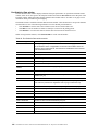
Table 7. Set Config port parameters
Parameter
26
Description
AdminState
Port administrative state: online, offline, diagnostics, or down.
LinkSpeed
1 Gbps or 2 Gbps.
PortType
Type of port.
Intel Blade Server Fibre Channel Switch Module SBCEFCSW / FC Expansion Card SBFCM Guide
Table 7. Set Config port parameters (continued)
Parameter
Description
TLPortMode
Initiates the configuration of external ports attributes. Indicates whether using
initiator or target devices on the loop. If you specify [port_number], the display
will present attributes for that port only; otherwise, all attributes for all ports will
be available for configuration.
ISLSecurity
E_Port security. Determines which switches a port will establish a link with.
•
•
•
Any - Will link with any switch.
Ours - Will link only to another Fibre Channel switch module.
None - The port will not establish an ISL link.
SymbolicPortName
Descriptive name.
ALFairness
Default is switch that has priority.
ARB_FF
Use ARB_FF instead of idles on loop FCAL option.
InteropCredit
Number of buffer-to-buffer credits per port. 0 means the default (12) is
unchanged.
ExtCredit
Extended credit port.
FANEnable
Fabric Address Notification. If enabled, notifies logged-in NL_Ports of the
FL_Port address, port name, and node name.
LCFEnable
Link control frame preference, R_CTL = 0xC.
MFSEnable
Multi-frame sequence bundling.
MFS_TOV
MFS limit for camp on.
MSEnable
Management Server enable on this port.
NoClose
Do not close unless another device arbitrates.
I/O Stream Guard
Enables or disables the suppression of RSCN messages.
IVIEnable
Not applicable.
CheckAlps
Close before sending frames to new target.
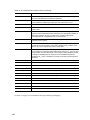
switch
Initiates an editing session in which to change switch configuration settings. Each parameter is
displayed, one line at a time and prompts you for a value. For each parameter, type a new value or
press the Enter key to accept the current value shown in brackets. Type q to cancel the configuration.
Table 8. Set Config switch parameters
Parameter
27
Description
AdminState
Switch administrative state: online, offline, or diagnostics.
Broadcast Enable
Enables (True) or disables (False) forwarding if broadcasting frames.
InbandEnabled
Enables (True) or disables (False) the ability to manage the switch over an
ISL.
DefaultDomainID
Default domain ID setting.
DomainIDLock
Prevents (True) or allows (False) dynamic reassignment of the domain ID.
Table 8. Set Config switch parameters (continued)
Parameter
Description
SymbolicName
Descriptive name.
R_T_TOV
Receiver Transmitter Timeout Value. Specifies the number of milliseconds a
port is to wait to receive a response from another port. The default is 100.
R_A_TOV
Resource Allocation Timeout Value. The number of milliseconds the switch
waits to allow two ports to allocate enough resources to establish a link. The
default is 10000.
E_D_TOV
Error Detect Timeout Value. The number of milliseconds a port is to wait for
errors to clear. The default is 2000 msec.
FS_TOV
Fabric Stability Timeout Value. The default is 5000 msec.
DS_TOV
Distributed Services Timeout Value (Management Server, Name Server).
The default is 5000 msec.
PrincipalPriority
The priority used in the FC-SW-2 principal switch selection algorithm. 1 is
high, 255 is low.
ConfigDescription
The name for the configuration. The default is undefined.
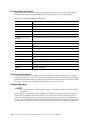
threshold
Initiates a configuration session by which to generate and log alarms for selected events. Each event,
its thresholds, and sampling interval is displayed, one line at a time and you are prompted for a value.
For each parameter, enter a new value or press the Enter key to accept the current value shown in
brackets. These parameters must be saved in a configuration and activated before they will take effect.
See the “Config command” on page 10 for information about saving and activating a configuration.
Table 9 describes the Set Config threshold parameters.
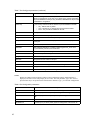
Table 9. Set Config threshold parameters
Parameter
28
Description
Threshold Monitoring Enabled
Master enable/disable parameter for all events. Enables (True) or
disables (False) the generation of all enabled event alarms.
CRCErrorsMonitoringEnabled
DecodeErrorsMonitoringEnabled
ISLMonitoringEnabled
LoginMonitoringEnabled
LogoutMonitoringEnabled
LOSMonitoringEnabled
The event type enable/disable parameter. Enables (True) or disables
(False) the generation of alarms for each of the following events:
Rising Trigger
The event count above which an event is logged. Once the count
exceeds the rising threshold, one alarm is logged. The switch will not
generate another alarm for that event until the count falls below the
falling threshold and rises again above the rising threshold.
Falling Trigger
The event count above which an event becomes eligible for logging in
the alarm log.
Sample Window
The period of time in seconds in which to count events.
•
•
•
•
•
•
CRC errors
Decode errors
ISL connection count
Login errors
Logout errors
Loss-of-signal errors
Intel Blade Server Fibre Channel Switch Module SBCEFCSW / FC Expansion Card SBFCM Guide
zoning
Initiates an editing session in which to change switch zoning attributes. Each parameter is displayed,
one line at a time, and you are prompted for a value. For each parameter, enter a new value or press
the Enter key to accept the current value shown in brackets.
Table 10. Set Config zoning parameters
Parameter
Description
AutoSave
Determines whether zoning changes will be saved to flash (nonvolatile) memory (On)
or to RAM (volatile) (Off). The default is On.
Default
Determines communication among ports/devices in the absence of an active zone set.
“All” enables all ports/devices to communicate with one another. “None” prohibits
communication among ports/devices.
Examples
The following is an example of the Set Config Port command.
FCSM: user1> admin start
FCSM (admin) : user1> config edit
FCSM (admin-config) : user1> set config port 0
A list of attributes with formatting and current values will follow.
Enter a new value or simply press the ENTER key to accept the current value.
If you wish to terminate this process before reaching the end of the list
press 'q' or 'Q' and the ENTER key to do so.
Configuring Port Number:
0
-----------------------AdminState
(1=Online, 2=Offline, 3=Diagnostics, 4=Down) [Online
]
LinkSpeed
(1=1Gb/s, 2=2Gb/s, 3=Auto)
[Auto
]
PortType
(TL / GL / G / F / FL / Donor)
[GL
]
TLPortMode
(1=TLTargetMode, 2=TLInitiatorMode)
[TLTargetMode]
ISLSecurity
(Any / Ours / None)
[Any
]
SymPortName
(string, max=32 chars)
[Port0
]
ALFairness
(True / False)
[False
]
ARB_FF
(True / False)
[False
]
[0
]
ExtCredit
(dec value, increments of 11, non-loop only) [0
]
FANEnable
(True / False)
[True
]
LCFEnable
(True / False)
[False
]
MFSEnable
(True / False)
[True
]
MFS_TOV
(decimal value, 10-20480 msec)
[10
]
MSEnable
(True / False)
[True
]
NoClose
(True / False)
InteropCredit (decimal value, 0-255)
29
[False
]
IOStreamGuard (Enable / Disable)
[Disabled
]
VIEnable
(True / False)
[False
]
CheckAlps
(True / False)
[False
]
Finished configuring attributes.
This configuration must be saved (see config save command) and
activated (see config activate command) before it can take effect.
To discard this configuration use the config cancel command.
The following is an example of the Set Config Switch command.
FCSM: user1> admin start
FCSM (admin) : user1> config edit
FCSM (admin-config) : user1> set config switch
A list of attributes with formatting and current values will follow.
Enter a new value or simply press the ENTER key to accept the current value.
If you wish to terminate this process before reaching the end of the list
press 'q' or 'Q' and the ENTER key to do so.
AdminState
(1=Online, 2=Offline, 3=Diagnostics) [Online]
BroadcastEnabled
(True / False)
[True]
InbandEnabled
(True / False)
[True]
DefaultDomainID
(decimal value, 1-239)
[1]
DomainIDLock
(True / False)
[False]
SymbolicName
(string,max=32 chars)
R_T_TOV
(decimal value, 1-1000 msec)
[100]
R_A_TOV
(decimal value, 100-100000 msec)
[10000]
E_D_TOV
(decimal value, 10-20000 msec)
[2000]
FS_TOV
(decimal value, 100-100000 msec)
[5000]
DS_TOV
(decimal value, 100-100000 msec)
[5000]
PrincipalPriority (decimal value, 1-255)
ConfigDescription
(string, max=64 chars)
[Fibre Channel Switch Module]
[254]
[Fibre Channel Switch Module]
Finished configuring attributes.
This configuration must be saved (see config save command) and
activated (see config activate command) before it can take effect.
To discard this configuration use the config cancel command.
The following is an example of the Set Config Threshold command.
FCSM (admin-config) : user1> set config threshold
A list of attributes with formatting and current values will follow.
Enter a new value or simply press the ENTER key to accept the current value.
If you wish to terminate this process before reaching the end of the list
press 'q' or 'Q' and the ENTER key to do so.
30
ThresholdMonitoringEnabled
(True / False)
[False]
CRCErrorsMonitoringEnabled
(True / False)
[False]
RisingTrigger
(decimal value, 1-1000)
[25
]
FallingTrigger
(decimal value, 0-1000)
[1
]
SampleWindow
(decimal value, 1-1000 sec)
[10
]
Intel Blade Server Fibre Channel Switch Module SBCEFCSW / FC Expansion Card SBFCM Guide
DecodeErrorsMonitoringEnabled
(True / False)
[True ]
RisingTrigger
(decimal value, 1-1000)
[200
]
FallingTrigger
(decimal value, 0-1000)
[0
]
SampleWindow
(decimal value, 1-1000 sec)
[10
]
(True / False)
[True ]
RisingTrigger
(decimal value, 1-1000)
[2
]
FallingTrigger
(decimal value, 0-1000)
[0
]
SampleWindow
(decimal value, 1-1000 sec)
[10
]
(True / False)
[True ]
RisingTrigger
(decimal value, 1-1000)
[5
]
FallingTrigger
(decimal value, 0-1000)
[1
]
SampleWindow
(decimal value, 1-1000 sec)
[10
]
(True / False)
[True ]
RisingTrigger
(decimal value, 1-1000)
[5
]
FallingTrigger
(decimal value, 0-1000)
[1
]
SampleWindow
(decimal value, 1-1000 sec)
[10
]
ISLMonitoringEnabled
LoginMonitoringEnabled
LogoutMonitoringEnabled
LOSMonitoringEnabled
(True / False)
[True ]
RisingTrigger
(decimal value, 1-1000)
[100
]
FallingTrigger
(decimal value, 0-1000)
[5
]
SampleWindow
(decimal value, 1-1000 sec)
[10
]
The following is an example of the Set Config Zoning command.
FCSM: user1> admin start
FCSM (admin) : user1> config edit
FCSM (admin-config) : user1> set config zoning
A list of attributes with formatting and current values will follow.
Enter a new value or simply press the ENTER key to accept the current value.
If you wish to terminate this process before reaching the end of the list
press 'q' or 'Q' and the ENTER key to do so.
AutoSave
(True / False)
[True]
Default
(All / None)
[All ]
Finished configuring attributes.
This configuration must be saved (see config save command) and
activated (see config activate command) before it can take effect.
To discard this configuration use the config cancel command.
31
Set Log command
Specifies the type of entries to be entered in the event log. The log is a storage file contained on the switch.
The log can hold a maximum of 200 entries. When the log becomes full, the entries are replaced, starting with
the oldest entry, to produce a list of the last 200 events which occurred. Log entries are created for ports,
components, and event severity levels.
Authority
Admin
Syntax
set log
archive
clear
component [list]
level [level]
port [port_list]
restore
save
start (default)
stop
Keywords
archive
Archives the log entries to a file on the switch named logfile that can be downloaded from the switch
using FTP. To download the log file, open an FTP session, log in with an account name of images
and password of images, and type get logfile.
clear
Clears all log entries.
component [list]
Specifies one or more components to monitor for events. Use spaces to delimit values in the list. Use
one or more of the following values:
All
Monitors all components. To maintain optimal switch performance, do not use this setting with
the Level keyword set to Info.
Blade
Not applicable
Chassis
Not applicable
Eport
Monitors all E_Ports.
Mgmtserver
Monitors management server status.
Nameserver
Monitors name server status.
None
Monitors none of the component events.
Other
Monitors other miscellaneous events.
32
Intel Blade Server Fibre Channel Switch Module SBCEFCSW / FC Expansion Card SBFCM Guide
Port
Monitors all port events.
Switch
Monitors switch management events.
Zoning
Monitors zoning conflict events.
level [level]
Specifies the severity level given by [level] to use in monitoring events for the specified components
or ports. [level] can be one of the following values:
Critical
Monitors critical events.
Warn
Monitors warning events.
Info
Monitors informational events. To maintain optimal switch performance, do not use this setting
with the Component keyword set to All.
None
Monitors none of the severity levels.
port [port_list]
Specifies one or more ports to monitor for events. Use one of the following values:
[port_list]
Specifies port or ports to monitor. Use spaces to delimit values in the list. Ports are numbered
beginning with 0.
All
Specifies all ports.
None
Disables monitoring on all ports.
restore
Returns the port, component, and level settings to the default values.
save
Saves the log settings for the component, level, and port. These settings remain in effect after a switch
reset. The log settings can be viewed using the Show Log Settings command. To export log entries to
a file, use the Set Log Archive command.
start
Starts the logging of events based on the Port, Component, and Level keywords assigned to the
current configuration. The logging continues until you enter the Set Log Stop command.
stop
Stops logging of events.
Notes
To maintain optimal switch performance, do not set the Component keyword to All and the Level keyword to
Info at the same time.
33
Set Port command
Sets port state and speed for the specified port temporarily until the next switch reset or new configuration
activation. This command also clears port counters. For information about port numbering and mapping, see
Table 37 on page 124.
✏ NOTE
For external ports (0,15), all port parameters apply. For internal ports, only the port state setting is
configurable.
Authority
Admin
Syntax
set port [port_number]
• bypass [alpa] (for external ports only)
• clear
• enable [alpa] (for external ports only)
• speed [transmission_speed]
• state [state]
Keywords
[port_number]
Specifies the port. Ports are numbered beginning with 0. For information about port numbering and
mapping, see Table 37 on page 124.
bypass [alpa]
Sends a Loop Port Bypass (LPB) to a specific Arbitrated Loop Physical Address (ALPA) or to all
ALPAs on the arbitrated loop. [alpa] can be a specific ALPA or the keyword ALL to choose all
ALPAs.
clear
Clears the counters on the specified port.
enable [alpa]
Sends a Loop Port Enable (LPE) to all ALPAs on the arbitrated loop. [alpa] can be a specific ALPA
or the keyword ALL to choose all ALPAs.
speed [transmission_speed]
Specifies the transmission speed for the specified port. Use one of the following port speed values:
1Gbps
One gigabit per second.
2Gbps
Two gigabits per second.
Auto
The port speed is automatically detected.
state [state]
Specifies the administrative state for the specified port. Use one of the following port state values:
Online
Places the port online.
Offline
Places the port offline.
Diagnostics
Prepares the port for testing.
Down
Disables the port.
34
Intel Blade Server Fibre Channel Switch Module SBCEFCSW / FC Expansion Card SBFCM Guide
Set Setup command
Changes SNMP and blade server configuration settings. The switch maintains one SNMP configuration and
one configuration.
Authority
Admin
Syntax
set setup
snmp
system
Keywords
snmp
Prompts you, line-by-line, to change SNMP configuration settings. Table 11 describes the SNMP
fields. For each parameter, enter a new value or press the Enter key to accept the current value shown
in brackets.
Table 11. SNMP configuration settings
Entry
35
Description
Contact
Specifies the name of the person to be contacted to respond to trap events.
The default is Undefined.
Location
Specifies the name of the switch location. The default is Undefined.
Trap [1-5] Address
Specifies the IP address to which SNMP traps are sent.
Trap [1-5] Port
Specifies the port for which SNMP traps are sent.
Trap [1-5] Severity
Specifies the severity level to use when monitoring trap events. The default is
Warning.
Trap [1-5] Enabled
Specifies whether traps (event information) are enabled or disabled (default).
ReadCommunity
Read Community Authentication. A write-only field; the value on the switch
and the SNMP management server must be the same.
WriteCommunity
Write Community Authentication. A write-only field; the value on the switch
and the SNMP management server must be the same.
TrapCommunity
Trap Community Authentication. A write-only field; the value on the switch and
the SNMP management server must be the same.
AuthFailureTrap
Specifies the IP address where a notification is sent in the event of an
authentication failure.
system
Prompts you, line-by-line, to change blade server configuration settings. Table 12 describes the
system configuration fields. For each parameter, enter a new value or press the Enter key to accept the
current value shown in brackets.
Table 12. System configuration settings
Entry
Description
Eth0NetworkAddress
Ethernet Internet protocol (IP) address
Eth0NetworkMask
Ethernet subnet mask address for the Ethernet port.
Eth0GatewayIPAddress
Ethernet IP address gateway
Eth0NetworkDiscovery
Ethernet boot method (1 - Static).
Note: BootP, DHCP, and RARP do not apply
AdminTimeout
Specifies the amount of time in minutes the switch waits before terminating an
idle Admin session. Zero (0) disables the time out threshold. The default is 30;
the maximum is 1440.
Security Enabled
Enables or disables the enforcement of account names and passwords.
Remote Log Enabled
Whether remote logging is enabled or disabled. If enabled, log information is
saved to a remote host that supports the systole protocol.
RemoteLogHost IP Address
The IP address of the host that will receive the remote log information if
remote logging is enabled.
Notes
The two components of security are user authentication and fabric security. The user must be authenticated
before gaining access to a switch. If an invalid account name/password combination is entered, that user can
not access the switch, and thus cannot gain access to the fabric. If security is enabled (True) and a valid
account name/password combination is entered, that user can access the switch but can not execute any
command that exceeds their authority (privileges) level. If security is disabled (False) and a valid account
name/password combination is entered, that user has access to all switches in the fabric and can execute all
commands (both user and admin), regardless of their authority (privileges) level.
Examples
The following is an example of the Set Setup SNMP command.
FCSM: user1> admin start
FCSM (admin) : user1> set setup snmp
A list of attributes with formatting and current values will follow.
Enter a new value or simply press the ENTER key to accept the current value.
If you wish to terminate this process before reaching the end of the list
press 'q' or 'Q' and the ENTER key to do so.
Trap Severity Options
--------------------unknown, emergency, alert, critical, error, warning, notify, info, debug, mark
Contact
Location
Trap1Address
36
(string, max=32 chars)
(string, max=32 chars)
(dot-notated IP Address)
[<sysContact undefined> ]
[<sysLocation undefined>]
[10.0.0.1
]
Intel Blade Server Fibre Channel Switch Module SBCEFCSW / FC Expansion Card SBFCM Guide
Trap1Port
Trap1Severity
Trap1Enabled
Trap2Address
Trap2Port
Trap2Severity
Trap2Enabled
Trap3Address
Trap3Port
Trap3Severity
Trap3Enabled
Trap4Address
Trap4Port
Trap4Severity
Trap4Enabled
Trap5Address
Trap5Port
Trap5Severity
Trap5Enabled
ReadCommunity
WriteCommunity
TrapCommunity
AuthFailureTrap
(decimal value)
(see allowed options above)
(True / False)
(dot-notated IP Address)
(decimal value)
(see allowed options above)
(True / False)
(dot-notated IP Address)
(decimal value)
(see allowed options above)
(True / False)
(dot-notated IP Address)
(decimal value)
(see allowed options above)
(True / False)
(dot-notated IP Address)
(decimal value)
(see allowed options above)
(True / False)
(string, max=32 chars)
(string, max=32 chars)
(string, max=32 chars)
(True / False)
[162
[warning
[False
[0.0.0.0
[162
[warning
[False
[0.0.0.0
[162
[warning
[False
[0.0.0.0
[162
[warning
[False
[0.0.0.0
[162
[warning
[False
[public
[private
[public
[False
]
]
]
]
]
]
]
]
]
]
]
]
]
]
]
]
]
]
]
]
]
]
]
Do you want to save and activate this snmp setup? (y/n): [n]
The following is an example of the Set Setup System command.
FCSM: user1> admin start
FCSM (admin) : user1> set setup system
A list of attributes with formatting and current values will follow.
Enter a new value or simply press the ENTER key to accept the current value.
If you wish to terminate this process before reaching the end of the list
press 'q' or 'Q' and the ENTER key to do so.
Eth0NetworkAddress
Eth0NetworkMask
Eth0GatewayAddress
Eth0NetworkDiscovery
AdminTimeout
SecurityEnabled
LocalLogEnabled
RemoteLogEnabled
RemoteLogHostAddress
(dot-notated IP Address)
(dot-notated IP Address)
(dot-notated IP Address)
(1=Static, 2=Bootp, 3=Dhcp, 4=Rarp)
(dec value 0-1440 minutes, 0=never)
(True / False)
(True / False)
(True / False)
(dot-notated IP Address)
[10.90.10.93 ]
[255.255.252.0]
[10.20.8.254 ]
[Static
]
[30
]
[False
]
[True
]
[False
]
[10.0.0.254
]
Do you want to save and activate this system setup? (y/n): [n]
37
Show command
Displays fabric, switch, and port operational information.
Authority
User
Syntax
show
about
alarm
broadcast
chassis
config [option]
domains
donor
fabric
interface
log [option]
lsdb
mem [count]
ns [option]
pagebreak
perf [option]
port [port_number]
post log
setup [option]
steering [domain_id]
support
switch
topology
users
version
Keywords
about
Displays an introductory set of information about operational attributes of the switch. This keyword
is equivalent to the Version keyword.
alarm
Displays the last 200 alarm entries.
broadcast
Displays the broadcast tree information and all ports that are currently transmitting and receiving
broadcast frames.
chassis
Not applicable
config [option]
Displays switch and port configuration attributes. For more information, see the “Show Config
command” on page 45.
38
Intel Blade Server Fibre Channel Switch Module SBCEFCSW / FC Expansion Card SBFCM Guide
domains
Displays a list of each domain and its worldwide name in the fabric.
donor
Displays list of current donor configuration for all ports.
fabric
Displays list of each domain, fabric ID, worldwide name, node IP address, port IP address, and
symbolic name in the fabric.
interface
Displays the status of the active network interfaces.
log [option]
Displays log entries. See the “Show Log command” on page 48.
lsdb
Displays Link State database information.
mem [count]
Displays information about memory activity for the number of seconds given by [count]. If you omit
[count], the value 1 is used. Displayed memory values are in units of 1 KB.
✏ NOTE
This keyword will display memory activity updates until [count] is reached; it cannot be
interrupted. Therefore, avoid using large values for [count].
ns [option]
Displays name server information for the specified [option]. If you omit [option], name server
information for the local domain ID is displayed. [option] can have the following values:
all
Displays name server information for all switches and ports.
[domain_id]
Displays name server information for the switch given by [domain_id]. [domain_id] is a switch
domain ID.
[port_id]
Displays name server information for the port given by [port_id]. [port_id] is a port Fibre
Channel address.
pagebreak
Displays the current pagebreak setting. The pagebreak setting limits the display of information to 20
lines (On) or allows the continuous display of information without a break (Off).
perf [option]
Displays performance information for all ports. See the “Show Perf command” on page 50.
port [port_number]
Displays operational information for the port given by [port_number]. Ports are numbered beginning
with 0. If the port number is omitted, information is displayed for all ports. Table 13 on page 40
describes the port parameters. For information about port numbering and mapping, see Table 37 on
page 124.
✏ NOTE
For external ports (0,15), all parameters apply. For internal ports (1 through 14) only
AdminState applies.
39
Table 13. Show Port parameters
Entry
40
Description
AIinit
Incremented each time the port begins AL initialization.
AIinitError
Number of times the port entered initialization and the initialization failed.
ClassXFramesIn
Number of class x frames received by this port.
ClassXFramesOut
Number of class x frames sent by this port.
ClassXWordsIn
Number of class x words received by this port.
ClassXWordsOut
Number of class x words sent by this port.
DecodeError
Decoding error detected.
EpConnects
Number of times an E_Port connects through ISL negotiation.
FBusy
Number of times the switch sent a F_BSY because Class 2 frame could not be
delivered within ED_TOV time. Number of class 2 and class 3 fabric busy (F_BSY)
frames generated by this port in response to incoming frames. This usually
indicates a busy condition on the fabric or N_port that is preventing delivery of this
frame.
Flowerrors
Received a frame when there were no available credits.
FReject
Number of frames from devices that were rejected.
InvalidCRC
Invalid CRC detected.
InvalidDestAddr
Invalid destination address detected.
LIP ALPD ALPS
Number of F7, AL_PS LIPs, or AL_PD (vendor specific) resets, performed.
LIPF7ALPS
This LIP is used to reinitialize the loop. An L_port, identified by AL_PS, may have
noticed a performance degradation and is trying to restore the loop.
LIPF8ALPS
This LIP denotes a loop failure detected by the L_port identified by AL_PS.
LIPF7F7
A loop initialization primitive frame used to acquire a valid AL_PA.
LIPF8F7
A loop initialization primitive frame used to indicate that a loop failure has been
detected at the receiver.
Link Failures
Number of optical link failures detected by this port. A link failure is a loss of
synchronization for a period of time greater than the value of R_T_TOV or by loss of
signal while not in the offline state. A loss of signal causes the switch to attempt to
re-establish the link. If the link is not re-established by the time specified by
R_T_TOV, a link failure is counted. A link reset is performed after a link failure.
Login
Time when user logged in.
Logout
Time when user logged out.
LoopTimeouts
A 2-second timeout as specified by FC-AL-2.
LossOfSync
Number of synchronization losses (>100 ms) detected by this port. A loss of
synchronization is detected by receipt of an invalid transmission word.
PrimSeqErrors
Primitive sequence errors detected.
RxLinkResets
Number of link reset primitives received from an attached device.
RxOfflineSeq
Number of offline sequences received. An OLS is issued for link initialization, a
Receive & Recognize Not_Operational (NOS) state, or to enter the offline state.
Intel Blade Server Fibre Channel Switch Module SBCEFCSW / FC Expansion Card SBFCM Guide
Table 13. Show Port parameters (continued)
Entry
Description
TotalErrors
Total number of errors detected.
TotalLIPsRecvd
Number of loop initialization primitive frames received by this port.
TotalLinkResets
Total number of link reset primitives.
TotalOfflineSeq
Total number of Offline Sequences issued by this port.
TotalRxFrames
Total number of frames received by this port.
TotalRxWords
Total number of words received by this port.
TotalTxFrames
Total number of frames issued by this port.
TotalTxWords
Total number of words issued by this port.
TxLinkResets
Number of Link Resets issued by this port.
TxOfflineSeq
Total number of Offline Sequences issued by this port.
TxWait
Time waiting to transmit when blocked with no credit. Measured in FC Word times.
post log
Displays the POST log which contains results from the POST.
setup [option]
Displays setup attributes for the system, SNMP, and the switch manufacturer. See the “Show Setup
command” on page 52.
steering [domain_id]
Displays the routes that data takes to the switch given by [domain_id]. If you omit [domain_id], the
system displays routes for all switches in the fabric.
support
Executes a series of commands that display a complete description of the switch, its configuration,
and operation. The display can be captured from the screen and used for diagnosing problems. This
keyword is intended for use at the request of your authorized maintenance provider. The following
commands are executed:
• Date
• Alias List
• Config List
• Date
• History
• Ps
• Show (About, Alarm, Backtrace, Chassis, Config Port, Config Switch, Dev, Dev Settings,
Domains, Donor, Fabric, Log, Log Settings, Lsdb, Mem, Ns, Perf, Port, Setup Mfg, Setup Snmp,
Setup System, Steering, Switch, Topology, Users)
• Uptime
• User Accounts
• Whoami
• Zoneset (Active, List)
• Zoning (History, Limits, List)
41
switch
Displays switch operational information.
topology
Displays all connected devices.
users
Displays a list of logged-in users. This is equivalent to the User List command.
version
Displays an introductory set of information about operational attributes of the switch. This keyword
is equivalent to the About keyword.
Examples
The following is an example of the Show Setup SNMP command.
FCSM: user1> show setup snmp
SNMP Information
---------------Contact
<sysContact undefined>
Location
<sysLocation undefined>
Description
42
Fibre Channel Switch Module
Trap1Address
10.0.0.1
Trap1Port
162
Trap1Severity
warning
Trap1Enabled
False
Trap2Address
0.0.0.0
Trap2Port
162
Trap2Severity
warning
Trap2Enabled
False
Trap3Address
0.0.0.0
Trap3Port
162
Trap3Severity
warning
Trap3Enabled
False
Trap4Address
0.0.0.0
Trap4Port
162
Trap4Severity
warning
Trap4Enabled
False
Trap5Address
0.0.0.0
Trap5Port
162
Trap5Severity
warning
Trap5Enabled
False
ObjectID
1.3.6.1.4.1.1663.1.1.1.1.16
AuthFailureTrap
False
Intel Blade Server Fibre Channel Switch Module SBCEFCSW / FC Expansion Card SBFCM Guide
The following is an example of the Show Topology command.
FCSM: user1> show topology
Unique ID Key
------------A = ALPA,
D = Domain ID,
P = Port ID
Loc
Local
Port
----
Type
----
PortWWN
-------
Rem
Ext:15
E
20:0f:00:c0:dd:00:90:fb E
Remote
Unique
Type NodeWWN
---- -------
ID
------
10:00:00:c0:dd:00:90:d74 (0x4) D
The following is an example of the Show Topology (for Port #15) command.
FCSM: user1> show topology 15
Local Link Information
---------------------Port
Ext2:15
PortID
020f00
PortWWN
20:0f:00:c0:dd:00:90:fb
PortType
E
Remote Link Information
----------------------Remote Switch
PortNumber
10
DomainID
04
NodeWWN
10:00:00:c0:dd:00:90:d7
PortType
E
Description Switch
IPAddress
10.0.0.3
The following is an example of the Show Port command.
FCSM: user1> show port 0
Port Number: 0
------------
43
AdminState
Online
PortID
640000
AsicNumber
0
PortWWN
20:00:00:c0:dd:00:91:03
AsicPort
0
RunningType
E
ConfigType
GL
SFPPartNumber
FTRJ-8519-3-2.5
DiagStatus
Passed
SFPRevision
X1
EpConnState
Connected
SFPType
100-M5-SN-I
EpIsoReason
NotApplicable
SFPVendor
FINISAR CORP.
LinkSpeed
2Gb/s
SFPVendorID
00659000
LinkState
Active
SymbolicName
Port0
LoginStatus
LoggedIn
SyncStatus
SyncAcquired
MaxCredit
12
XmitterEnabled
True
OperationalState Online
ALInit
11
FlowErrors
0
PrimSeqErrors
0
ALInitError
1
FReject
0
RxLinkResets
0
Class2FramesIn
0
InvalidCRC
0
RxOfflineSeq
0
Class2FramesOut 0
InvalidDestAddr 0
TotalErrors
1
Class2WordsIn
0
LIP_AL_PD_AL_PS 0
TotalLIPsRecvd
15
Class2WordsOut
0
LIP_F7_AL_PS
0
TotalLinkResets 0
Class3FramesIn
0
LIP_F7_F7
15
TotalOfflineSeq 0
Class3FramesOut 0
LIP_F8_AL_PS
0
TotalRxFrames
0
Class3Toss
0
LIP_F8_F7
0
TotalRxWords
0
Class3WordsIn
0
LinkFailures
0
TotalTxFrames
0
Class3WordsOut
0
Login
7
TotalTxWords
0
DecodeErrors
0
Logout
6
TxLinkResets
0
EpConnects
7
LoopTimeouts
0
TxOfflineSeq
0
FBusy
0
LossOfSync
1
TxWaits
0
The following is an example of the Show Switch command.
FCSM: user1> show switch
Switch Information
------------------
44
SymbolicName
Fibre Channel Switch Module
SwitchWWN
10:00:00:c0:dd:00:91:03
SwitchType
SBXL52
PROMVersion
V1.4.0.1-0 (Thu Sep 12 17:46:41 2002)
CreditPool
0
DomainID
1 (0x1)
FirstPortAddress
010000
FlashSize - MBytes
128
LogLevel
Critical
MaxPorts
16
NumberOfResets
14
ReasonForLastReset
NormalReset
SWImageVersion (1) - build date
V1.4.0.18-3 (Thu Sep 19 03:55:16 2002)
SWImageVersion (2) - build date
V1.4.0.19-1 (Fri Sep 20 03:56:20 2002)
ActiveConfiguration
default
ActiveSWImage
2
AdminState
Online
AdminModeActive
False
BeaconOnStatus
False
OperationalState
Online
PrincipalSwitchRole
True
BoardTemp (1) - Degrees Celsius
50
BoardTemp (2) - Degrees Celsius
50
SwitchDiagnosticsStatus
Passed
SwitchTemperatureStatus
Normal
Intel Blade Server Fibre Channel Switch Module SBCEFCSW / FC Expansion Card SBFCM Guide
Show Config command
Display port, switch, alarm threshold, and zoning attributes for the current configuration.
Authority
User
Syntax
show config
port [port_number]
switch
threshold
zoning
Keywords
port [port_number]
Displays configuration parameters for the port number given by [port_number]. Ports are numbered
beginning with 0. If the port value is omitted, all ports are specified.
✏ NOTE
For external ports (0,15), all parameters apply. For internal ports (1 through 14) only
AdminState applies. For information about port numbering and mapping, see Table 37 on
page 124.
switch
Displays configuration parameters for the switch.
threshold
Displays alarm threshold parameters for the switch.
zoning
Displays zoning configuration parameters for the switch.
Examples
The following is an example of the Show Config Port command.
FCSM: user1> show config port 15
Configuration Name: lei
------------------Port Number: 15
------------
45
AdminState
Online
LinkSpeed
Auto
PortType
GL
TLPortMode
TLTargetMode
ISLSecurity
Any
SymbolicName
Port15
ALFairness
False
ARB_FF
False
InteropCredit
0
ExtCredit
0
FANEnable
True
LCFEnable
False
MFSEnable
True
MFS_TOV
10
MSEnable
True
NoClose
False
IOStreamGuard
Disabled
VIEnable
False
CheckAlps
False
The following is an example of the Show Config Switch command.
FCSM: user1> show config switch
Configuration Name: lei
------------------Switch Configuration Information
-------------------------------AdminState
Online
BroadcastEnabled
True
InbandEnabled
True
DomainID
1 (0x1)
DomainIDLock
False
SymbolicName
Fibre Channel Switch Module
R_T_TOV
100
R_A_TOV
10000
E_D_TOV
2000
FS_TOV
5000
DS_TOV
5000
PrincipalPriority
254
ConfigDescription
Fibre Channel Switch Module
ConfigLastSavedBy
Initial
ConfigLastSavedOn
Initial
The following is an example of the Show Config Threshold command.
FCSM: user1> show config threshold
Configuration Name: default
------------------Threshold Configuration Information
----------------------------------ThresholdMonitoringEnabled
True
CRCErrorsMonitoringEnabled
True
RisingTrigger
25
FallingTrigger
1
SampleWindow
10
DecodeErrorsMonitoringEnabled
46
True
RisingTrigger
200
FallingTrigger
0
SampleWindow
10
Intel Blade Server Fibre Channel Switch Module SBCEFCSW / FC Expansion Card SBFCM Guide
ISLMonitoringEnabled
True
RisingTrigger
2
FallingTrigger
0
SampleWindow
10
LoginMonitoringEnabled
True
RisingTrigger
5
FallingTrigger
1
SampleWindow
10
LogoutMonitoringEnabled
True
RisingTrigger
5
FallingTrigger
1
SampleWindow
10
LOSMonitoringEnabled
True
RisingTrigger
100
FallingTrigger
5
SampleWindow
10
The following is an example of the Show Config Zoning command.
FCSM: user1> show config zoning
Configuration Name: default
------------------Zoning Configuration Information
--------------------------------
47
AutoSave
True
Default
All
Show Log command
Displays the contents of the log or the parameters used to create entries in the log. The log contains a
maximum of 200 entries. When the log reaches its entry capacity, subsequent entries overwrite the existing
entries, beginning with the oldest.
Authority
User
Syntax
show log
component
level
options
port
settings
Keywords
component
Displays the components currently being monitored for events.
level
Displays the event severity level needed to create an entry in the log. If the severity level occurs on a
port or on a component which is not defined, no entry is made in the log.
options
Displays the options used to set the component and log level attributes.
port
Displays the ports being monitored for events. If an event occurs which is of the defined level and on
a defined component, but not on a defined port, no entry is made in the log.
settings
Displays the current settings for component, level and port. This command is equivalent to executing
the following commands separately: Show Log Component, Show Log Level, and Show Log Port.
Examples
The following is an example of the Show Log Component command.
FCSM: user1> show log component
Current setting(s) for log component: NameServer
The following is an example of the Show Log Level command.
FCSM: user1> show log level
Current settings for log
-----------------------level
Critical
The following is an example of the Show Log Options command.
FCSM: user1> show log options
Allowed options for '
level': Critical,Warn,Info,None
Allowed options for 'component':
All,None,NameServer,MgmtServer,Zoning,Switch,Chassis,Blade,Port,Eport,Snmp,Other
48
Intel Blade Server Fibre Channel Switch Module SBCEFCSW / FC Expansion Card SBFCM Guide
Current setting(s) for log port: 0 1 2 3 4 5 6 7 8 9 10 11 12 13 14 15
The following is an example of the Show Log command.
[327][Wed Jan 25 09:36:54.860 1989][I][Eport:0xdd00b8b6.304.4 Port: 0/8][Eport
State = E_A0_GET_DOMAIN_ID]
[328][Wed Jan 25 09:36:54.860 1989][I][Eport:0xdd00b8b6.304.4 Port: 0/8][FSPF
PortUp state=0]
[329][Wed Jan 25 09:36:54.861 1989][I][Eport:0xdd00b8b6.304.4 Port:
0/8][Sending init hello]
[330][Wed Jan 25 09:36:54.861 1989][I][Eport:0xdd00b8b6.304.4 Port:
0/8][Processing EFP, oxid= 0x8]
[331][Wed Jan 25 09:36:54.861 1989][I][Eport:0xdd00b8b6.304.4 Port: 0/8][Eport
State = E_A2_IDLE]
[332][Wed Jan 25 09:36:54.861 1989][I][Eport:0xdd00b8b6.304.4 Port: 0/8][EFP,
WWN= 0x100000c0dd00b845, len= 0x30]
[333][Wed Jan 25 09:36:54.864 1989][I][Eport:0xdd00b8b6.304.4 Port:
0/8][Sending LSU oxid= 0xc: type= 1]
[334][Wed Jan 25 09:36:54.864 1989][I][Eport:0xdd00b8b6.304.4 Port: 0/8][Send
Zone Merge Request]
[335][Wed Jan 25 09:36:54.865 1989][I][Eport:0xdd00b8b6.304.4 Port: 0/8][LSDB
Xchg timer set]
[336][Wed Jan 25 09:36:54.865 1989][I][Eport:0xdd00b8b6.304.4 Port:
0/8][Setting attribute Oper.UserPort.0.8.EpConnState Connected]
49
Show Perf command
Displays port performance in frames per second and bytes per second. If you omit the keyword, the command
displays data transmitted (out), data received (in), and total data transmitted and received in frames per second
and bytes per second.
Authority
User
Syntax
show perf
byte
inbyte
outbyte [port_number]
frame [port_number]
inframe [port_number]
outframe [port_number]
errors [port_number]
Keywords
byte
Displays continuous performance data in total bytes per second transmitted and received for all ports.
Type q and press the Enter key to stop the display.
inbyte
Displays continuous performance data in bytes per second received for all ports. Type q and press the
Enter key to stop the display.
outbyte [port_number]
Displays continuous performance data in bytes per second transmitted for all ports. Type q and press
the Enter key to stop the display.
frame [port_number]
Displays continuous performance data in total frames per second transmitted and received for all
ports. Type q and press the Enter key to stop the display.
inframe [port_number]
Displays continuous performance data in frames per second received for all ports. Type q and press
the Enter key to stop the display.
outframe [port_number]
Displays continuous performance data in frames per second transmitted for all ports. Type q and
press the Enter key to stop the display.
errors [port_number]
Displays continuous error counts for all ports. Type q and press the Enter key to stop the display.
50
Intel Blade Server Fibre Channel Switch Module SBCEFCSW / FC Expansion Card SBFCM Guide
Examples
The following is an example of the Show Perf command.
FCSM: user1>: show perf
Bytes/s
Port
51
Bytes/s
Bytes/s
Frames/s
Frames/s
Frames/s
(out)
(total)
(in)
(out)
(total)
(in)
----
-------
-------
-------
--------
--------
--------
Ext1:0
0
0
0
0
0
0
Ext2:15 0
0
0
0
0
0
Bay1
0
0
0
0
0
0
Bay2
0
0
0
0
0
0
Bay3
0
0
0
0
0
0
Bay4
0
0
0
0
0
0
Bay5
0
0
0
0
0
0
Bay6
0
0
0
0
0
0
Bay7
0
0
0
0
0
0
Bay8
0
0
0
0
0
0
Bay9
0
0
0
0
0
0
Bay10
0
0
0
0
0
0
Bay11
0
0
0
0
0
0
Bay12
0
0
0
0
0
0
Bay13
0
0
0
0
0
0
Bay14
0
0
0
0
0
0
Show Setup command
Displays the current SNMP and system settings.
Authority
User
Syntax
show setup
mfg
snmp
system
Keywords
mfg
Displays manufacturing information about the switch.
snmp
Displays the current SNMP settings.
system
Displays the current system settings.
Examples
The following is an example of the Show Setup Mfg command.
FCSM: user1> show setup mfg
Manufacturing Information
------------------------BoardSerialNumber
P9
BrandName
BuildDate
Unknown
ChassisPartNumber
Unknown
ChassisSerialNumber
P9
MACAddress
00:c0:dd:00:91:02
PlanarPartNumber
Unknown
SwitchSymbolicName
Fibre Channel Switch Module
SwitchWWN
10:00:00:c0:dd:00:91:03
SystemDescription
SystemObjectID
Fibre Channel Switch Module
1.3.6.1.4.1.1663.1.1.1.1.16
The following is an example of the Show Setup Snmp command.
FCSM: user1> show setup snmp
SNMP Information
----------------
52
Contact
<sysContact undefined>
Location
<sysLocation undefined>
Description
Fibre Channel Switch Module
Trap1Address
10.0.0.254
Trap1Port
162
Trap1Severity
warning
Intel Blade Server Fibre Channel Switch Module SBCEFCSW / FC Expansion Card SBFCM Guide
Trap1Enabled
False
Trap2Address
0.0.0.0
Trap2Port
162
Trap2Severity
warning
Trap2Enabled
False
Trap3Address
0.0.0.0
Trap3Port
162
Trap3Severity
warning
Trap3Enabled
False
Trap4Address
0.0.0.0
Trap4Port
162
Trap4Severity
warning
Trap4Enabled
False
Trap5Address
0.0.0.0
Trap5Port
162
Trap5Severity
warning
Trap5Enabled
False
ObjectID
1.3.6.1.4.1.1663.1.1.1.1.16
AuthFailureTrap
False
The following is an example of the Show Setup System command.
FCSM: user1> show setup system
System Information
------------------
53
Eth0NetworkAddress
10.20.8.188
Eth0NetworkMask
255.255.252.0
Eth0GatewayAddress
10.20.8.254
Eth0NetworkDiscovery
Static
AdminTimeout
30
SecurityEnabled
False
LocalLogEnabled
True
RemoteLogEnabled
False
RemoteLogHostAddress
10.0.0.254
Shutdown command
Terminates all data transfers on the switch at convenient points and closes the Telnet session. Always power
cycle the switch after entering this command.
Authority
Admin
Syntax
shutdown
Notes
Always use this command to effect an orderly shutdown before removing power from the switch. Failure to do
so could damage the flash memory and the switch configuration.
54
Intel Blade Server Fibre Channel Switch Module SBCEFCSW / FC Expansion Card SBFCM Guide
Test command
Tests switch module ports using internal (SerDes level), external small form-factor pluggable (SFP), and
online loopback tests. Internal and external tests require that the switch module port be placed in diagnostic
mode. See the “Set Port command” on page 34 for information about changing the port administrative state.
While the test is running, the remaining ports on the switch remain fully operational. See “Port testing” on
page 117 for more information.
Authority
Admin
Syntax
test
port [port_number] [test_type]
cancel
status
Keywords
port [port_number] [test_type]
Tests the port given by [port_number] using the test given by [test_type]. If you omit [test_type],
Internal is used. [test_type] can have the following values:
Internal (for internal and external ports)
Tests the SerDes. This is the default. The port must be in diagnostics mode to perform this test.
External (for external ports only)
Tests both the SerDes and SFP. The port must be in diagnostics mode to perform this test, and a
loopback plug must be installed in the SFP.
Online (for internal and external ports)
Tests one online port.
cancel
Cancels the online test in progress.
status
Displays the status of a test in progress, or if there is no test in progress, the status of the test that was
executed last.
Examples
To run Internal (SerDes) or External (SFP) port tests, complete the following steps:
1. To start an admin session, type the following command:
admin start
2.
Place the port in Diagnostics mode by typing the following command (x = port number):
set port x state diagnostics
3.
55
Insert the loopback plug into the SFP on the selected port (for external port test only).
4.
Choose one of the two types of port loopback tests to run:
• To run an internal loopback test, type the following command:
test x internal
•
To run an external loopback test, type the following command. A loopback plug must be installed for
this test to pass.
test x external
✏ NOTE
The external loopback test can be performed only on external switch module ports.
After the test type has been chosen and the command executed, a message on the screen will appear
detailing the test results.
5.
After the test is run, put the port back into online state by typing the following command (x = port
number):
set port x state online
6.
To verify the port is back online, type the following command. The contents of the AdminState field
should be Online.
show port x
The online node-to-node test can test only one port at a time, and that port must be online and connected to an
external device or a blade server Fibre Channel expansion card. To run the online node-to-node test, complete
the following steps:
1. To start an admin session, type the following command:
admin start
2.
To run the online node-to-node test, type the following command:
test x online
A series of test parameters are displayed on the screen.
3.
Press the Enter key to accept each default parameter value, or type a new value for each parameter and
press the Enter key. The TestLength parameter is the number of frames sent, the FrameSize (256 byte
maximum in some cases) parameter is the number of bytes in each frame, and the DataPattern parameter
is the pattern in the payload. Before running the test, make sure that the device attached to the port can
handle the test parameters.
FCSM (admin) : user1> test x online
A list of attributes with formatting and current values will follow.
Enter a new value or simply press the ENTER key to accept the default value. If
you wish to terminate this process before reaching the end of the list press
'q'
or 'Q' and the ENTER key to do so.
TestLength
(decimal value, 1-4294967295)
[100
]
FrameSize
(decimal value, 36-2148)
[256
]
DataPattern
(32-bit hex value or 'Default') [Default]
StopOnError
(True/False)
[False
Do you want to start the test? (y/n) [n]
4.
56
After all parameter values are defined, press the Y key to start the test.
Intel Blade Server Fibre Channel Switch Module SBCEFCSW / FC Expansion Card SBFCM Guide
]
Uptime command
Displays the elapsed time since the switch was last reset and reset method.
Authority
User
Syntax
uptime
Examples
The following is an example of the Uptime command.
FCSM: user1> uptime
Elapsed up time
: 0 day(s), 2 hour(s), 28 min(s), 44 sec(s)
Reason last reset: NormalReset
57
User command
Administers or displays user accounts.
Authority
Admin. The List keyword is available with User authority.
Syntax
user
accounts
add
delete [account_name]
list
Keywords
accounts
Displays all user accounts that exist on the switch.
add
Add a user account to the switch. After this command is executed, the administrator will be prompted
for the information needed to establish the user account. A switch can have a maximum of 15 user
accounts. Account names are limited to 15 characters; passwords are limited to 31 characters.
delete [account_name]
Deletes the account name given by [account_name] from the switch.
list
Displays the list of users currently logged in and their session numbers. Provides the same function as
the Show Users command. This keyword is valid for User authority and does not require an admin
session.
Examples
The following is an example of the User Accounts command.
FCSM (admin) : user1> user accounts
Current list of user accounts
----------------------------images
(admin authority = False)
admin
(admin authority = True)
USERID
(admin authority = True)
The following is an example of the User Add command.
FCSM (admin) : user1> user add
Press 'q' and the ENTER key to abort this command.
account name (1-15 chars)
: user3
account password (4-20 chars)
:
please confirm account password:
should this account have admin authority? (y/n) [n] : y
OK to add user account 'user3' with admin authority?
Please confirm (y/n): [n] y
58
Intel Blade Server Fibre Channel Switch Module SBCEFCSW / FC Expansion Card SBFCM Guide
The following is an example of the User Delete command.
FCSM (admin) : user1> user del user3
The user account will be deleted.
Please confirm (y/n): [n] y
The following is an example of the User List command.
FCSM (admin) : user1> user list
Current list of users logged in
------------------------------admin@OB-session1 - in admin mode
admin@OB-session2
user1@OB-session3
59
Whoami command
Command Displays the account name, session number, and switch domain ID for the Telnet session.
Authority
User
Syntax
whoami
Examples
The following is an example of the Whoami command.
FCSM: user1> whoami
User name
: admin@OB-session3
Switch name
: Fibre Channel Switch Module
Switch domain ID: 100 (0x64)
60
Intel Blade Server Fibre Channel Switch Module SBCEFCSW / FC Expansion Card SBFCM Guide
Zone command
Manages zones and zone membership on a switch. The Zone command defines members (ports and devices)
for a single switch. Zones are members of zone sets.
Authority
Admin authority and a Zoning Edit session. See the “Zoning command” on page 66 for information about
starting a Zoning Edit session. The List, Members, and Zonesets keywords are available with User authority
and do not require a Zoning Edit session.
Syntax
zone
add [zone] [members]
copy [zone_source] [zone_destination]
create [zone]
delete [zone]
list
members [zone]
remove [zone] [members]
rename [zone_old] [zone_new]
type [zone] [zone_type]
zonesets [zone]
Keywords
add [zone] [members]
Specifies one or more ports given by [members] to add to the zone named [zone]. A zone can have a
maximum of 256 members. [members] can have one of the following formats:
• Domain ID and port number pair (domain ID, port number). Domain IDs and port numbers are in
decimal format. Ports are numbered beginning with 0.
• 6-character hexadecimal device Fibre Channel address (hex)
• 16-character hexadecimal port worldwide name (PWWN) with the format
xx:xx:xx:xx:xx:xx:xx:xx.
• Alias name
The application verifies that the [zone] format is correct, but does not validate that such a port exists.
copy [zone_source] [zone_destination]
Creates a new zone named [zone_destination] and copies the membership into it from the zone given
by [zone_source].
create [zone]
Creates a zone with the name given by [zone]. An zone name must begin with a letter and be no
longer than 64 characters. Valid characters are 0-9, A-Z, a-z, &, _, and -. The zoning database
supports a maximum of 256 zones.
delete [zone]
Deletes the specified zone given by [zone] from the zoning database. If the zone is a member of the
active zone set, the zone will not be removed from the active zone set until the active zone set is
deactivated.
list
Displays a list of all zones and the zone sets of which they are members. This keyword is valid for
User authority and does not require a zoning edit session.
61
members [zone]
Displays all members of the zone given by [zone]. This keyword is available with User authority and
does not require a Zoning Edit session.
remove [zone] [members]
Removes the ports given by [members] from the zone given by [zone]. [members] can have one of the
following formats:
• Domain ID and port number pair (Domain ID, Port Number). Domain IDs and port numbers are
in decimal. Ports are numbered beginning with 0.
• 6-character hexadecimal device Fibre Channel address (hex)
• 16-character hexadecimal port worldwide name (PWWN) with the format
xx:xx:xx:xx:xx:xx:xx:xx.
• Alias name
rename [zone_old] [zone_new]
Renames the zone given by [zone_old] to the zone given by [zone_new].
type [zone] [zone_type]
Specifies the zone type given by [zone_type] to be assigned to the zone name given by [zone]. If you
omit the [zone_type], the system displays the zone type for the zone given by [zone]. [zone_type] can
be one of the following:
soft
Name server zone
hardacl
Access control list hard zone
hardvpf
Virtual private fabric hard zone
zonesets [zone]
Displays all zone sets of which the zone given by [zone] is a member. This keyword is available with
User authority and does not require a Zoning Edit session.
Examples
The following is an example of the Zone List command.
FCSM: user1> zone list
Zone
ZoneSet
------------------wwn_b0241f
zone_set_1
wwn_23bd31
zone_set_1
wwn_221416
zone_set_1
wwn_2215c3
zone_set_1
62
Intel Blade Server Fibre Channel Switch Module SBCEFCSW / FC Expansion Card SBFCM Guide
wwn_0160ed
zone_set_1
wwn_c001b0
zone_set_1
wwn_401248
zone_set_1
wwn_02402f
zone_set_1
wwn_22412f
zone_set_1
The following is an example of the Zone Members command.
FCSM: user1> zone members wwn_b0241f
Current List of Members for Zone: wwn_b0241f
--------------------------------50:06:04:82:bf:d2:18:c2
50:06:04:82:bf:d2:18:d2
21:00:00:e0:8b:02:41:2f
The following is an example of the Zone Zonesets command.
FCSM: user1> zone zonesets zone1
Current List of ZoneSets for Zone: wwn_b0241f
---------------------------------zone_set_1
63
Zoneset command
Manages zone sets and zone set membership across the fabric.
Authority
Admin authority and a Zoning Edit session. See the “Zoning command” on page 66 for information about
starting a Zoning Edit session. The Active, List, Zones keywords are available with User authority. You must
close the Zoning Edit session before using the Activate and Deactivate keywords.
Syntax
zoneset
activate [zone_set]
active
add [zone_set] [zone_list]
copy [zone_set_source] [zone_set_destination]
create [zone_set]
deactivate
delete [zone_set]
list
remove [zone_set] [zone_list]
rename [zone_set_old] [zone_set_new]
zones [zone_set]
Keywords
activate [zone_set]
Activates the zone set given by [zone_set]. This keyword deactivates the active zone set. Close the
Zoning Edit session before using this keyword.
active
Displays the name of the active zone set. This keyword is available with User authority and does not
require a Zoning Edit session.
add [zone_set] [zone_list]
Adds a list of zones and aliases given by [zone_list] to the zone set given by [zone_set]. Zone and
alias names are delimited by spaces in [zone_list]. This keyword requires a Zoning Edit session.
copy [zone_set_source] [zone_set_destination]
Creates a new zone set named [zone_set_destination] and copies into it the membership from the
zone set given by [zone_set_source]. This keyword requires a Zoning Edit session.
create [zone_set]
Creates the zone set with the name given by [zone_set]. A zone set name must begin with a letter and
be no longer than 64 characters. Valid characters are 0-9, A-Z, a-z, &, _, and -. This keyword requires
a Zoning Edit session. The zoning database supports a maximum of 256 zone sets.
deactivate
Deactivates the active zone set. Close the Zoning Edit session before using this keyword.
delete [zone_set]
Deletes the zone set given by [zone_set]. If the specified zone set is active, the command is suspended
until the zone set is deactivated. This keyword requires a Zoning Edit session.
list
Displays a list of all zone sets. This keyword is available with User authority and does not require a
Zoning Edit session.
64
Intel Blade Server Fibre Channel Switch Module SBCEFCSW / FC Expansion Card SBFCM Guide
remove [zone_set] [zone_list]
Removes a list of zones and aliases given by [zone_list] from the zone set given by [zone_set]. Zone
and alias names are delimited by spaces in [zone_list]. If [zone_set] is the active zone set, the zone
will not be removed until the zone set has been deactivated. This keyword requires a Zoning Edit
session.
rename [zone_set_old] [zone_set_new]
Renames the zone set given by [zone_set_old] to the name given by [zone_set_new]. You can rename
the active zone set. This keyword requires a Zoning Edit session.
zones [zone_set]
Displays all zones that are members of the zone set given by [zone_set]. This keyword is available
with User authority and does not need a Zoning Edit session.
Notes
•
•
•
A zone set must be active for its definitions to be applied to the fabric.
Only one zone set can be active at one time.
A zone can be a member of more than one zone set.
Examples
The following is an example of the Zoneset Active command.
FCSM: user1> zoneset active
The active ZoneSet is:
Beta
The following is an example of the Zoneset List command.
FCSM: user1> zoneset list
Current List of ZoneSets
-----------------------alpha
beta
The following is an example of the Zoneset Zones command.
FCSM: user1> zoneset zones ssss
Current List of Zones for ZoneSet: ssss
---------------------------------zone1
zone2
zone3
65
Zoning command
Opens a Zoning Edit session in which to create and manage zone sets and zones. See the “Zone command” on
page 61” and the “Zoneset command” on page 64” for information about managing zone and zone sets.
Authority
Admin. The List keyword is available with User authority.
Syntax
zoning
active
cancel
clear
edit
history
limits
list
restore
save
Keywords
active
Displays membership information for the active zone set including member zones and zone members.
cancel
Closes the current Zoning Edit session. Any unsaved changes are lost.
clear
Clears all inactive zone sets from the volatile edit copy of the zoning database. This keyword does not
affect the nonvolatile zoning database. However, if you enter the Zoning Clear command followed by
the Zoning Save command, the nonvolatile zoning database will be cleared from the switch. The
preferred method for clearing the zoning database from the switch is the Reset Zoning command.
edit
Opens a Zoning Edit session.
history
Displays a history of zoning modifications including the following:
• Time of the most recent zone set activation or deactivation and the user who performed it
• Time of the most recent modifications to the zoning database and the user who made them.
• Checksum for the zoning database.
limits
Displays the maximum limits imposed on the zoning database for the number of zone sets, zones,
aliases, members per zone, members per alias, and total members.
list
Lists all fabric zoning definitions. This keyword is available with User authority.
restore
Reverts the changes to the zoning database that have been made during the current Zoning Edit
session since the last Zoning Save command was entered.
save
Saves changes made during the current Zoning Edit session. The system will inform you that the zone
set must be activated to implement any changes. This does not apply if you entered the Zoning Clear
command during the Zoning Edit session.
66
Intel Blade Server Fibre Channel Switch Module SBCEFCSW / FC Expansion Card SBFCM Guide
Examples
The following is an example of the Zoning Edit command.
FCSM: user1> admin start
FCSM (admin) : user1> zoning edit
FCSM (admin-zoning) : user1>
.
.
FCSM (admin-zoning) : user1> zoning cancel
Zoning edit mode will be canceled.
Please confirm (y/n): [n]
FCSM (admin) : user1> admin end
The following is an example of the Zoning List command.
FCSM: user1> zoning list
Active ZoneSet Information
ZoneSet
Zone
ZoneMember
-------------------------------wwn
wwn_b0241f
50:06:04:82:bf:d2:18:c2
50:06:04:82:bf:d2:18:d2
21:00:00:e0:8b:02:41:2f
wwn_23bd31
50:06:04:82:bf:d2:18:c2
50:06:04:82:bf:d2:18:d2
10:00:00:00:c9:23:bd:31
wwn_221416
50:06:04:82:bf:d2:18:c2
50:06:04:82:bf:d2:18:d2
10:00:00:00:c9:22:14:16
wwn_2215c3
50:06:04:82:bf:d2:18:c2
50:06:04:82:bf:d2:18:d2
10:00:00:00:c9:22:15:c3
67
y
Configured Zoning Information
ZoneSet
Zone
ZoneMember
-------------------------------wwn
wwn_b0241f
50:06:04:82:bf:d2:18:c2
50:06:04:82:bf:d2:18:d2
21:00:00:e0:8b:02:41:2f
wwn_23bd31
50:06:04:82:bf:d2:18:c2
50:06:04:82:bf:d2:18:d2
10:00:00:00:c9:23:bd:31
wwn_221416
50:06:04:82:bf:d2:18:c2
50:06:04:82:bf:d2:18:d2
10:00:00:00:c9:22:14:16
wwn_2215c3
50:06:04:82:bf:d2:18:c2
50:06:04:82:bf:d2:18:d2
10:00:00:00:c9:22:15:c3
68
Intel Blade Server Fibre Channel Switch Module SBCEFCSW / FC Expansion Card SBFCM Guide
Using the SAN Utility
You can use the SAN Utility application to access and configure switch modules. For information about
installing, uninstalling, and starting the SAN Utility application, see the Fibre Channel Switch Module
Installation Guide. The SAN Utility application can be installed on an SBCE blade server or an external
network management workstation configured with one of the operating systems described in the Fibre
Channel Switch Installation Guide.
To manage your switch modules and fabrics, the SAN Utility application provides two basic windows:
Topology and Faceplate. The SAN Utility user interface, its elements, and the tasks that you can perform from
the Faceplate window and Topology window are described in this chapter.
Important: Before you configure your switch module, be sure that the management modules in your SBCE®
unit are properly configured. In addition, to access and manage your switch module from an external
environment, you might need to enable certain features, such as the external ports and external management
over all ports. See the applicable Intel® Blade Server Chassis SBCE Installation and User’s Guide publications
on the Intel® Server Chassis SBCE Resource CD for more information. For more detailed information about
configuring your switch module, see the Intel® Blade Server Fibre Channel Switch Module SBCEFCSW
Installation Guide on the Resource CD.
SAN Utility user interface
The Topology window and Faceplate window share the following common elements:
• Menu bar
• Toolbar
• Fabric tree
• Graphic window
• Data window and tabs
• Working Status indicator
The Topology window displays all of the switch modules that are enabled and the connections between switch
modules and other Fibre Channel devices, as shown in Figure 1.
Figure 1. Topology window
69
The Faceplate window displays the front of a single switch module and its active ports, as shown in Figure 2
Figure 2. Faceplate window
Menu bar
The menu bar is displayed at the top of the Faceplate window and Topology window. Depending on which
window is open, the menu bar has similar menu selections. Figure 3 shows menu items that are available in the
Topology window and the Faceplate window. In the figure, menu items available from the faceplate window,
but not in the Topology window are shown with a gray background.
Figure 3. Menu bar selection examples
70
Intel Blade Server Fibre Channel Switch Module SBCEFCSW / FC Expansion Card SBFCM Guide
Some menu selections have shortcut keys as shown in Table 14.
Table 14. Menu shortcut keys
Shortcut key
Menu selection
F5
View ” Refresh
Ctrl+O
File ” Open View File
In addition to the menu bar, both the Topology and Faceplate windows have context-sensitive menus that open
when you click in the graphic window with the right mouse button. See “Opening the Faceplate window and
pop-up menus” on page 76 for more information about these pop-up menus.
Toolbar
The toolbar consists of a row of graphical buttons that you can use to access SAN Utility functions as shown
and described in Table 15 The toolbar buttons are an alternative method to using the menu bar.
Table 15. Toolbar buttons
Toolbar button
71
Toolbar button name
Description
Add Fabric
Adds a new fabric
Open View File
Opens an existing fabric view file
Save View As
Saves the current fabric view to a file
Refresh
Polls the fabric to update the Topology or
Faceplate window with the current information
Help Topics
Opens the online help
Edit Zoning
Opens the Edit Zoning window (available only in
the Faceplate window)
Fabric tree
The fabric tree, in the FC Fabric pane, lists the managed fabrics and their switch modules. To adjust the
window, click and drag the moveable window border. An entry handle to the left of an entry in the tree
indicates that you can expand the entry. When you click the handle or double-click the entry, the entry expands
to show its member switches. These fabric tree elements are shown in Figure 4 on page 72
Figure 4. Fabric tree
Each fabric tree entry has a small icon next to it that uses color to indicate the following operational status:
• A green switch module entry icon indicates that the switch is in normal operation.
• A green switch module entry icon indicates that the switch has a communications failure.
• A red switch
• A blue switch module entry icon indicates that the switch status is Unknown or that security is enabled on
the switch module but security is disabled on the fabric management switch.
• An amber switch module entry icon indicates that the switch is operational with errors.
You can use the fabric tree to access any fabric or switch module using the Topology or Faceplate window. You
can click a fabric entry to open the Topology window from the fabric tree. You can click a switch module entry
to open the Faceplate window from the fabric tree.
Graphic window
The graphic window as shown in Figure 1 on page 69 shows graphic information about fabrics and switch
modules such as the fabric topology and the switch faceplate. To adjust the window length, click and drag the
window border that it shares with the data window.
Data window and tabs
The data window as shown in Figure 2 on page 70 displays a table of data and statistics associated with the
selected tab. Use the scroll bar to browse through the data. The window length can be adjusted by clicking and
dragging the border that it shares with the graphic window.
To adjust the column width, move the pointer over the column heading border shared by two columns until a
right/left arrow graphic is displayed. Click and drag the arrow to the desired width. The data window tabs
show options for the types of information that you can display in the data window. These options vary
depending on the display.
72
Intel Blade Server Fibre Channel Switch Module SBCEFCSW / FC Expansion Card SBFCM Guide
Working status indicator
The working status indicator as shown in Figure 1 on page 69 is in the lower-right corner of the Topology
window and shows when the network management workstation is exchanging information with the fabric. As
conditions change, the fabric forwards this information to the network management workstation where it is
reflected in the various displays.
Using the Topology window
The Topology window shown in Figure 5 polls the selected fabric and displays its topology. switch modules
and interswitch links (ISL) are displayed in the graphic window and use color to indicate status. The following
functional elements are displayed in the Topology window when you click on the Data window tabs:
• Switch module and link status
• Working with switch modules and links
• Topology data windows
Figure 5. Topology window
Fibre Channel switch module and link status
The Fibre Channel switch module icon shape and color provide information about the switch and its
operational state. In the Topology window, lines represent links between switch modules. See Table 16 for
Fibre Channel switch module and link status and “Fabric status” on page 80 for more information about other
Topology window icons.
Table 16. Fibre Channel switch module and link status indicators
Switch module icon color
73
Status
Green
Normal Fibre Channel switch operation
Amber
Operational with errors
Red
Inactive or Fibre Channel switch failure
Blue
Unknown Fibre Channel device
Working with switch modules and links
Switch module and link icons are selectable and moveable and serve as access points for other windows and
menus. You select switch modules and links to display information, modify configurations, or delete them
from the window. The context-sensitive pop-up menus are accessible through the switch module and link
icons.
Click a switch module or link in the graphic window to display its status in the data window. To select multiple
switch modules or links, hold down the Ctrl key while selecting. When no switch modules or links are
selected, information about all switch modules is displayed. To deselect a switch module or link that is
currently selected, click the switch or link.
Different switch module icons will be displayed depending on the different switch vendor products present in
the attached fabric. See Table 17 on page 81 for a list of switch module icons and vendors. Attached switch
modules that are not manageable through the SAN Utility will be displayed as “third-party manageable”
switch icons. The topology configuration in Figure 6 shows an example of a switch fabric with third-party
switch modules.
Figure 6. Switch fabric showing third-party manageable switch modules
Arranging switch modules in the window
You can use the following two methods to arrange individual switch module icons:
• To move an individual switch module icon, click and drag the icon to another location in the graphic
window. Links stretch or contract to remain connected.
•
To arrange all switch module icons in the Topology window, click View / Layout Topology.
The Toggle Auto Layout check box in the View menu is selected by default so that the SAN Utility can
arrange the icons when you select Layout Topology.
You can save a custom arrangement, or layout, and restore that layout during a SAN Utility session. To create
a custom arrangement, arrange the icons; then, click View / Remember Layout. To restore the saved layout,
click View, clear the Toggle Auto Layout check box, and click Layout Topology.
74
Intel Blade Server Fibre Channel Switch Module SBCEFCSW / FC Expansion Card SBFCM Guide
Selecting switch modules and links
Selected switch module icons are highlighted in violet. Selected ISLs are highlighted in amber. You can select
switch modules and links by performing the following tasks:
• To select a switch module or a link, click the icon or link.
• To select multiple switch modules or links, hold down the Ctrl key and click the switch modules or links
that you want.
•
To select all switch modules or links, right-click in the graphic window background. Click Select All
Switches or click All Links from the pop-up menu.
To cancel a selection, press and hold the Ctrl key, and select the item again. To cancel multiple selections, click
in the graphic window background.
Topology data window tabs
The Topology Data window contains four tabs at the bottom of the window. When you click a tab, the
following information is displayed:
•
Name Server - Click the Name Server tab to display all devices that are logged with the name
server and their location within the current fabric configuration. See “Name Server Data window”
on page 108 for more information about your configuration.
•
Active Zoneset - Click the Active Zoneset tab to display the active zone set for the fabric,
including zones and their member ports. See “Active Zoneset Data window” on page 82 for more
information about this data window. See “Zoning a fabric” on page 82 for information about zone sets
and zones.
•
•
Switch - Click the Switch tab to display the current network and switch module configuration
data for the selected switches. See “Switch Data window” on page 94 for more information.
Link - Click the Link tab to display the current link status for the selected switch modules in the fabric.
Using the Faceplate window
The Faceplate window shown in Figure 7 and described in this section displays the switch module name and
operational state and the port status. The following functional elements are displayed in the Faceplate window
when you click on the Data window tabs:
• Port views and status
• Working with ports
• Faceplate data windows
Figure 7. Faceplate window
75
Opening the Faceplate window and pop-up menus
The Faceplate window shows the front of a single switch module and its ports. You can open the Faceplate
window and pop-up menus when you are in the Topology window by performing the following tasks:
• To open the Faceplate window when viewing the Topology window, click a switch module entry or icon in
the fabric tree, or double-click the switch module graphic.
• To open the fabric pop-up menu when viewing the Topology window, right-click the graphic window
background. The fabric pop-up menu displays selections to refresh the fabric, select all switch modules,
select all links, or layout topology.
• To open the switch module pop-up menu when viewing the Topology window, right-click the switch
module icon in the graphic window. The switch pop-up menu displays selections to refresh the switch,
delete the switch from the display, open the Switch Properties window, or open the Network Properties
window.
• To open the link pop-up menu, right-click the link. The Link pop-up menu displays a selection to delete
the link from the display.
• To open a Faceplate window pop-up menu, right-click the faceplate graphic in the Graphic window. The
faceplate pop-up menu displays selections to refresh the switch module, select all ports, manage switch,
port, and network properties, extend credits, and run the Port Loopback tests.
Port views and status
Port color and text provides information about the port and its operational state. Green indicates that the port is
active, and gray indicates that the port is inactive. The Faceplate window displays the following views of port
status corresponding to the View menu options in the Faceplate window:
• Port mode
• Port state
• Port speed
• Port media
See “Monitoring port status” on page 103 for more information about these displays.
Working with ports
Ports are selectable and serve as access points for other windows and menus. You select ports to display
information about them in the data window or to modify them. You cannot use the SAN Utility to select
internal bays and external ports at the same time; you must select either internal bays or external ports.
Context-sensitive pop-up menus and properties windows are accessible through the Faceplate window and port
icons.
Selecting ports
When you select a port, the port is highlighted with a white border. You can select ports in the following ways:
• To select one port, click the port in the Faceplate display.
• To select a range of either internal or external consecutive ports, select a port and then press and hold the
shift key and select another port. The application selects both end ports and all ports in between in port
number.
• To select several nonconsecutive ports, hold the Ctrl key while selecting ports.
•
To select all external ports, right-click anywhere on the switch module faceplate, and select Select All
Ports from the pop-up menu. To select all internal ports, click any blade server and select All
Ports from the pop-up menu.
To cancel a selection, press and hold the Ctrl key and select it again.
76
Intel Blade Server Fibre Channel Switch Module SBCEFCSW / FC Expansion Card SBFCM Guide
Opening pop-up menus
You can manage the switch module and its ports using the following methods:
• To open the pop-up menu, right-click anywhere in the graphic window. If no ports are selected, port
specific tasks are unavailable in the menu.
• To select one or more ports and open the Port pop-up menu, right-click a port.
Faceplate data window tabs
The Faceplate Data window contains six tabs at the bottom of the display. When you click a tab, the following
information is displayed:
•
Name Server - Click the Name Server tab to display all devices connected to the switch module that
are logged with the name server.
•
Switch - Click the Switch tab to display the current switch module configuration data.
•
Port Statistics - Click the Port Stats tab to display the port performance data for the selected port.
•
Port Information - Click the Port Info tab to display the port detail information for the selected port.
•
Configured Zonesets - Click the Configured Zonesets tab to display all zone sets, zones, and zone
membership in the zoning database.
•
Alarm Log - Click the Alarm Log tab to display the system error information.
Managing fabrics
This section describes the following four main tasks for managing fabrics:
• Setting up security
• Managing the fabric database
• Displaying fabric information
• Zoning a fabric
Setting up security
Access to a switch module and permission to configure a switch is managed through user accounts created by
a fabric administrator. A user account consists of an
account name, a password, and an authority level. The authority level determines
whether an account can merely monitor the switch module and fabric activity (User
authority), or change switch module configurations (Administrative authority). See “User command” on page
58 for information about administrating user accounts.
Fabric security determines the enforcement of user accounts on a switch module. A fabric administrator can
enable or disable the fabric security on a switch module using the Set Setup System command.
If fabric security is disabled (default), you can use the SAN Utility to log in to a switch module without an
account name and password. The Login name and Password fields in the Add a Fabric window are ignored,
and you are granted Admin authority. If fabric security is enabled, you must enter an account name and
password to log in to a switch module and add the fabric to the workspace. Having successfully added a fabric,
you can perform only those tasks in the SAN Utility that are granted by the authority level for that account. All
switch modules in a fabric should use the same fabric security value. See “Set Setup command” on page 35 for
information about the System keyword and the Security Enable parameter.
✏ NOTE
A switch module supports a combined maximum of 15 active login sessions. This includes SAN
Utility in-band and out-of-band login attempts, Telnet out-of-band login attempts, and SNMP out-ofband login sessions. Of this 15, there can be a maximum of 10 SAN Utility login attempts included in
the 15 total attempts. Additional logins are refused.
77
Managing the fabric database
A fabric database contains the set of fabrics that you have added during a SAN Utility session. Initially, a
Topology window with an empty fabric database opens. This section describes the following fabric database
management tasks:
• Adding a fabric
• Removing a fabric
• Opening a fabric view file
• Saving a fabric view file
• Rediscovering a fabric
• Adding a new switch module to a fabric
• Replacing a failed switch module in a fabric
• Deleting switch modules and links
Adding a fabric
Complete the following steps to add a fabric to the database:
1.
In the Faceplate window, click Fabric / Add Fabric.
The Add a New Fabric window opens, as shown in Figure 8
Figure 8. Add a New Fabric window
2.
In the Fabric name field, type a fabric name.
3.
In the IP address field, type the IP address of the switch module through which to manage the fabric.
4.
In the Login name field, type the initial default login ID, USERID. In the Password field, type
the initial default password, PASSW0RD (the sixth character is a zero, not the letter O). The user
ID and password are case sensitive.
✏ NOTE
The password is for the switch module and is stored in the switch firmware. You are not required to
type a user ID or password if security is disabled. See “Setting up security” on page 77. See “Set
Setup command” on page 35 for information about the Set Setup commands in the Telnet section to
log in, and obtain password and security information.
5.
Click Add fabric.
Removing a fabric
Complete the following steps to delete a fabric file from the database:
1. Select a fabric in the fabric tree.
2.
78
In the Faceplate window, click Fabric / Remove Fabric.
Intel Blade Server Fibre Channel Switch Module SBCEFCSW / FC Expansion Card SBFCM Guide
Opening a fabric view file
Complete the following steps to open an existing fabric view file:
1.
2.
3.
4.
In the Faceplate window, click File / Open View File, or click the Open icon.
If there is a change to the fabric you are using, you are prompted to save the changes to the view file
before opening a different view file.
The Open View window opens.
In the Open View window, type the name of the file you want to open.
Type a file password if necessary.
Click Load View File. If the fabric has changed, you are prompted to save the file before opening the
new view.
Saving a fabric view file
Complete the following steps to save a fabric view file:
2.
In the Faceplate window, click File / Save View As or click the Save icon.
The Save View window opens.
In the Save View window, type a new file name.
3.
4.
Click OK.
Type a file password, if necessary.
1.
Rediscovering a fabric
After making changes or deleting switch modules from a fabric view, refresh the fabric configuration. Use the
Rediscover Fabric option to clear the current fabric information that is displayed and rediscover the switch
module information. To rediscover a fabric, in the Faceplate window, click Fabric / Rediscover Fabric.
Adding a new switch module to a fabric
After you install a switch module into your Blade Server Chassis SBCE, the switch uses the default fabric
configuration settings. The default fabric configuration settings are as follows:
• Fabric zoning is sent to the switch module from the fabric.
• All external ports (0,15) are GL_Ports; all internal ports (1 through 14) are F_Ports.
• The default IP addresses are:
For switch module bay 3:
192.168.70.129
For switch module bay 4:
192.168.70.130
Complete the following steps to add a new switch module to a fabric and not make changes to the default
fabric configuration settings:
1. If the switch module is not new, to reset the switch to the factory configuration, in the Faceplate window,
click Switch / Restore Factory Defaults.
2. If you want to manage the switch module through the Ethernet port, configure the network SNMP
configuration using the Network Properties window. For more information, see “Network properties” on
page 100.
3. Configure any special switch settings.
✏ NOTE
4.
5.
79
To prevent communication with other switch modules in the fabric until the new switch is
configured, in the Zoning Config window, click None in the Default Visibility field. For more
information, see “Zoning configuration” on page 84.
Connect the interswitch links (ISL), but do not connect the devices.
In the Port Properties window, configure the port types for the new switch (GL_Port, TL_Port, Donor).
6.
7.
Connect the Fibre Channel devices to the switch module.
In the Edit Zoning window, make the necessary zoning changes.
Replacing a failed switch module in a fabric
Complete the following steps to replace a failed switch module for which an archive is available. See
“Restoring a switch module” on page 121 and “Archiving a switch module” on page 102 for more information.
1.
Remove the failed switch module. For more information, see the Installation Guide.
2.
3.
Install the new replacement switch module. For more information, see the Installation Guide.
Log in to the fabric through the replacement switch module. In the Topology window, select the
replacement switch module from the fabric tree.
4.
Click Switch / Restore.
The Restore Switch window opens.
In the Restore Switch window, type a name or select the archived switch configuration file to copy to the
switch module. For more information, see “Archiving a switch module” on page 102.
5.
6.
Click OK to write the configuration file to the switch module.
Deleting switch modules and links from the Topology display
The SAN Utility does not automatically delete switch modules or links that have failed or that are physically
removed. In this case, you can delete switch modules and links in the Topology window to bring the display up
to date. If you delete a switch or a link that is still active, the SAN Utility restores it automatically. You can
also refresh the display.
Complete the following steps to delete a switch module in the Topology window:
1. Select one or more switch modules in the Topology window.
2.
Click Switch / Delete.
Complete the following steps to delete a link:
1. Select one or more links in the Topology window.
2.
Click Switch / Delete.
Displaying fabric information
The Topology window is the primary tool for monitoring a fabric. The graphics window of the Topology
window provides status information for switch modules, interswitch links, and the Ethernet connection to the
network management workstation.
The data window tabs show name server, switch, and active zone set information. The Active Zoneset tab
shows the zone definitions for the active zone set. See “Switch Data window” on page 94 and “Name Server
Data window” on page 108 for information about the Switch Data and Name Server Data windows.
Fabric status
The fabric updates the Topology and Faceplate windows by forwarding changes in status to the network
management workstation as they occur. Use the fabric to update the display status, or you can refresh the
display at any time. To refresh the Topology window, use one of the following methods:
•
In the Topology window, click Refresh.
•
•
Click View / Refresh.
Press the F5 key.
•
Right-click anywhere in the background of the Topology window. Select Refresh Fabric from the popup menu.
The Topology window displays switch module and status icons that provide status information about switches,
interswitch links, and the Ethernet connection. The switch module icons indicate different vendor switches and
switch types. The switch module status icons, displayed on the left side of a switch, vary in shape and color.
Each switch module that is managed by an Ethernet Internet protocol (IP) has a colored Ethernet icon that is
80
Intel Blade Server Fibre Channel Switch Module SBCEFCSW / FC Expansion Card SBFCM Guide
displayed on the right side of the switch. A green Ethernet icon indicates normal operation, amber indicates
operational with errors, and red indicates inactive or failure. Table 17 on page 81 shows the different switch
module icons and their descriptions.
✏ NOTE
Different switch module icons are displayed depending on the different switch vendor products
presented in the attached fabric. For a list of switch module icons and vendors, see Table 17 on page
81 Attached switch modules that are not manageable through the SAN Utility are displayed as thirdparty manageable switch icons. The topology configuration in Figure 6 on page 74 shows an example
of a switch fabric with third-party switch modules.
Table 17. Topology window switch module and status icons
Switch module icon
Description
Fibre Channel switch module
QLogic 8-port Fibre Channel switch module
QLogic16-port Fibre Channel switch module
Inrange switch module
McData switch module
Brocade switch module
Other third-party switch modules
Switch communication normal (green)
Switch is operational with errors (amber)
Switch communication interrupted (red)
Switch management communication unknown (blue)
Fabric management switch Ethernet connection normal (green)
Fabric management switch Ethernet connection critical (red)
Fabric management switch Ethernet connection warning (amber)
81
Active Zoneset Data window
The Active Zoneset Data window displays the zone membership for the active zone set that resides on the
fabric management switch. The active zone set is the same on all switch modules in the fabric. You can
confirm this by adding a fabric through another switch module and comparing Active Zone Set displays.
To open the Active Zoneset Data window, click the Active Zoneset tab below the data window in the
Topology window. See “Zoning a fabric” for more information about zone sets and zones. See “Configured
Zonesets Data window” on page 96 for information about the zone set definitions on a specific switch module.
The Active Zoneset data window, shown in Figure 9 uses display conventions for expanding and contracting
entries that are similar to the fabric tree. An entry handle to the left of an entry in the fabric tree indicates that
you can expand the entry. Click this handle or double-click the following entries to expand or contract them:
• A zone set entry expands to show its member zones.
• A zone entry expands to show its member ports.
• A port entry expands to show the port Fibre Channel address.
• A Fibre Channel address entry expands to show the port worldwide name.
Figure 9. Active Zonesets window
Zoning a fabric
Fibre Channel fabrics use zoning to restrict or extend access to devices in the fabric. A zone is a named group
of devices that can communicate with each other.
You can use zoning to divide the ports and devices of the fabric into zones for more efficient and secure
communication among functionally grouped nodes. You can set the Auto Save and Default Visibility zoning
configuration parameters using the SAN Utility or the Set Config Zoning command. See “Auto save” on page
84 for information about the Auto Save parameter, see “Default visibility” on page 84 for information about
the Default Visibility parameter, and see “Using the Zoning Config window” on page 85 for information about
the Set Config Zoning command.
Zoning concepts
The following zoning concepts provide some context for the zoning tasks described in this section:
• Zones
• Aliases
• Zone sets
• Zoning database
• Zoning configuration
82
Intel Blade Server Fibre Channel Switch Module SBCEFCSW / FC Expansion Card SBFCM Guide
Zones
A zone is a named group of ports or devices that can communicate with each other. Membership in a zone is
defined by port number, device Fibre Channel address, or device World Wide Name (WWN). Zone members
can communicate only with members of the same zone. Zones can overlap; that is, a port or device can be a
member of more than one zone.
There are three zone types that are supported but have restrictive levels of communication. These zone types
are:
• Soft zone
• Access control list (ACL) - hard zone
• Virtual private fabric (VPF) - hard zone
Soft zoning
Soft zoning divides the fabric for purposes of controlling discovery. Members of the same soft zone
automatically discover and communicate freely with all other members of the same zone. The soft zone
boundary is not secure; traffic across soft zones can occur if addressed correctly. Soft zones that include
members from multiple switch modules need not include the ports of the interswitch links. Soft zone
boundaries yield to ACL and VPF zone boundaries. Soft zones can overlap; that is, a port can be a member of
more than one soft zone. Membership is defined by Fibre Channel address, port ID and domain ID, or
worldwide name. Soft zoning supports all port modes.
Access control list zones
Access control list (ACL) zoning divides the fabric for purposes of controlling discovery and inbound traffic.
ACL zoning is a type of hard zoning that is hardware enforced. This type of zoning is useful for controlling
access to certain devices without totally isolating them from the fabric. Members can communicate with each
other and transmit outside the ACL zone but cannot receive inbound traffic from outside the zone. The ACL
zone boundary is secure against inbound traffic. ACL zones can overlap; that is, a port can be a member of
more than one ACL zone. ACL zones that include members from multiple switch modules need not include
the ports of the interswitch links. ACL zone boundaries supersede soft zone boundaries but yield to VPF zone
boundaries. Membership can be defined only by port ID and domain ID. ACL zoning supports all port modes
except TL_Ports.
Virtual private fabric zones
Virtual private fabric (VPF) zoning divides the fabric for purposes of controlling discovery and both inbound
and outbound traffic. This type of zoning is useful for providing security and reserving paths between devices
to guarantee bandwidth. VPF zoning is a type of hard zoning that is hardware enforced. Members can transmit
to and receive only from members of the same VPF zone. The VPF zone boundary is secure against both
inbound and outbound traffic. VPF zones that include members from multiple switch modules must include
the ports of the interswitch links. VPF zones cannot overlap; that is, a port can be a member of only one VPF
zone. VPF zone boundaries supersede both soft and ACL zone boundaries. Membership can be defined only
by port ID and domain ID. VPF zoning supports all port modes.
✏ NOTE
Domain ID conflicts can result in automatic reassignment of switch module domain IDs. These
reassignments are not reflected in zones that use domain ID and port number pairs or Fibre Channel
addresses to define their membership. Be sure to reconfigure zones that are affected by a domain ID
change. To prevent zoning definitions from becoming invalid when the membership is defined by
domain ID/port number or Fibre Channel address, you must lock domain IDs.
Aliases
To make it easier to add a group of ports or devices to one or more zones, you can create an alias. An alias is a
named set of ports or devices that are grouped together for convenience. Unlike zones, aliases impose no
communication restrictions between its members. You can add an alias to one or more zones. However, you
cannot add a zone to an alias, nor can an alias be a member of another alias.
83
Zone sets
A zone set is a named group of zones. A zone can be a member of more than one zone set. All zones that are
not members of a zone set belong to the orphan zone set. The orphan zone set is saved to the switch module.
Each switch module in the fabric maintains its own zoning database containing one or more zone sets. This
zoning database resides in nonvolatile or permanent memory and is therefore retained after a reset. For
information about displaying the zoning database, see “Configured Zonesets Data window” on page 96.
To apply zoning to a fabric, select a zone set and activate it. When you activate a zone set, the switch module
distributes that zone set to every switch in the fabric. Therefore, every switch module in the fabric will have
identical active zone sets. For information about displaying the active zone set, see “Active Zoneset Data
window” on page 82.
Zoning database
Each switch module has its own zoning database. The zoning database is made up of all aliases, zones, and
zone sets that have been created on the switch or received from other switch modules. The switch module
maintains two copies of the zoning database: one copy is maintained in temporary memory for editing
purposes; the second copy is maintained in permanent memory. Zoning database edits are made on an
individual switch basis and are not propagated to other switch modules in the fabric when saved.
The Auto Save zoning configuration parameter controls whether the temporary zoning database is
automatically saved in permanent memory. For more information about the Auto Save parameters, see
“Zoning configuration.”
The zoning limits for a fabric are:
• Maximum number of zonesets is 256
• Maximum number of zones is 256
• Maximum number of aliases is 256
• Maximum number of members per zone is 2000
• Maximum number of members per alias is 2000
• Maximum total number of zone and alias members is 2000
• Maximum total number of zone set members is 1000
Zoning configuration
You can set the zoning configuration parameters using the SAN Utility or the Set Zoning Config command.
For information about zoning configuration using the SAN Utility, see “Using the Zoning Config window” on
page 85 and “Set Config command” on page 26.
The following parameters make up the zoning configuration:
•
Auto Save
•
Default Visibility
Auto save
The Auto Save parameter determines whether changes to the active zone set that a switch module receives
from other switches in the fabric are saved to permanent memory on that switch module. Changes are saved
when an updated zone set is activated. Zoning changes are always saved to temporary memory. However, if
Auto Save is enabled, the switch module firmware saves changes to the active zone set in both temporary and
permanent memory. If Auto Save is disabled, changes to the active zone set are stored only in temporary
memory.
Default visibility
The Default Visibility parameter determines the level of communication that is permitted between devices
when there is no active zone set. The default visibility parameter can be set differently on each switch module.
When default visibility is enabled (set to All) on a switch module, all ports on the switch can communicate
with all ports on switch modules that also have the Default Visibility parameter set to Enabled. When default
visibility is disabled (set to None) on a switch module, none of the ports on that switch module can
communicate with any other switch in the fabric.
84
Intel Blade Server Fibre Channel Switch Module SBCEFCSW / FC Expansion Card SBFCM Guide
Using the Zoning Config window
Use the Zoning Config window to change the Auto Save and Default Visibility configuration parameters.
Complete the following steps to open the Zoning Config window and change configuration parameters:
1. In the Faceplate window, click Zoning / Edit Zoning Config.The Zoning Config window opens.
Figure 10. Zoning Config window
2. Make the necessary changes to the Auto Save and Default Visibility fields and click OK.
Restoring default zoning
Restoring the default zoning clears the switch module of all zoning definitions. Complete the following steps
to restore the default zoning for a switch module.
Attention: The use of this command will deactivate any active zone set. If the switch module is not isolated
from the fabric, this command will deactivate the active zone set for the entire fabric.
1.
In the Faceplate window, click Zoning / Restore Default Zoning.
2.
Click OK to confirm that you want to restore default zoning and save changes to the zoning database.
Merging fabrics and zoning
If you join two fabrics, the active zone sets from the two fabrics attempt to merge. The fabrics can consist of a
single switch module or many switches already connected together. The switch modules in the two fabrics
attempt to create a new active zone set containing the union of the active zone set of each fabric. The
propagation of zoning information affects only the active zone set, not the configured zone sets.
Zone merge failure
If a zone merge is unsuccessful, the interswitch links between the fabrics will isolate because of a zone merge
failure, which generates an alarm log entry. The reason for the E_Port isolation can also be determined by
viewing the port.
information. See the “Port Information Data window” on page 96 and the “Show command” on page 38 (Port
keyword).
A zone merge will fail if the two active zone sets have member zones with identical names that differ in
content or type. For example, consider Fabric A and Fabric B, each with a zone in its active zone set named
“ZS1.” Fabric A “ZS1” contains a member specified by Domain ID 1 and Port 1; Fabric B “ZS1” contains a
member specified by Domain ID 1 and Port 2. In this case, the merge fails, and the interswitch links between
the fabrics are isolated.
85
Zone merge failure recovery
When a zone merge failure occurs, the conflict that caused the failure must be resolved. You can correct a
failure due to a zone conflict by deactivating one of the active zone sets or editing the conflicting zones so that
their membership is the same. You can deactivate the active zone set on one switch module if the active zone
set on the other switch accurately defines your zoning needs. If not, you must edit the zone memberships and
reactivate the zone sets. For information about adding and removing zone members, see “Managing zones” on
page 89. To permit the fabrics to join, reset the ports that were isolated. See “Resetting a port” on page 113.
Using the Edit Zoning window
Use the Edit Zoning window to edit the zoning database for a specific switch module. To edit the zoning
database, in the Faceplate window, click Zone / Edit Zoning. The Edit Zoning window opens.
✏ NOTE
You can make changes only to an active zone set, which is stored in flash (nonvolatile) memory and
retained after setting a switch module.
Figure 11. Edit Zoning window
The Edit Zoning window displays a Zone Sets tree in the left pane and a Port and Device (or members) tree in
the right pane, as shown in Figure 11 Both trees use display conventions similar to the fabric tree for
expanding and contracting zone sets, zones, and ports. An expanded port shows the port Fibre Channel
address; an expanded address shows the port worldwide name. You can select zone sets, zones, and ports in the
following ways:
• Click a zone, zone set, or port icon.
• Right-click to select a zone set or zone and open the corresponding pop-up menu.
• Hold down the Shift key while clicking several consecutive icons.
• Hold down the Ctrl key while clicking several nonconsecutive icons.
Using the toolbar, pop-up menus, or a drag-and-drop method, you can create and manage zone sets and zones
in the zoning database. Click Apply to save your changes to the zoning database without closing the window.
Click OK to save your changes to the zoning database and close the window.
86
Intel Blade Server Fibre Channel Switch Module SBCEFCSW / FC Expansion Card SBFCM Guide
The following table explains the toolbar buttons and functions.
Table 18. Edit Zoning window toolbar buttons
Toolbar button
Function
Create a new zone set.
Create a new zone.
Create an additional name for a set of objects.
Add the selected zone to a zone set, or add the selected port to a zone.
Delete the selected zone from a zone set, or delete the selected port from a
zone.
Managing zone sets
Zoning a fabric involves creating a zone set, creating zones as zone set members, then adding devices as zone
members. The zoning database supports multiple zone sets to serve the different security and access needs of
your storage area network. Only one zone set can be active at one time. Managing zone sets involves the
following tasks:
• Creating zone sets
• Activating and deactivating zone sets
• Copying a zone to a zone set
• Removing a zone from one zone set or from all zone sets
• Removing a zone set
• Removing all zoning definitions
✏ NOTE
Changes that you make to the zoning database are limited to the managed switch module and do not
propagate to the rest of the fabric. To distribute changes to configured zone sets fabric-wide, you must
edit the zoning databases on the individual switch modules.
87
Creating a zone set
Complete the following steps to create a zone set:
1.
In the Faceplate window, click Zoning / Edit Zoning.
The Edit Zoning window opens.
2.
Click Edit / Create Zone Set.
The Create Zone Set window opens.
3.
Type a name for the zone set, and click OK. The new zone set name is displayed in the Zone Sets
window.
Complete one of the following tasks to create new zones in a zone set:
4.
•
•
5.
Right-click a zone set and select Create A Zone from the pop-up menu. In the Create A Zone
window, type a name for the new zone, and click OK. The new zone name is displayed in the
Zone Sets window.
To copy an existing zone into the new zone set, in the Faceplate window, select the zone and drag it
into the new zone set.
Click Apply to save changes to the zoning database.
Activating and deactivating a zone set
You must activate a zone set to apply its zoning definitions to the fabric. Only one zone set can be active at one
time. When you activate a zone set, the switch module distributes that zone set to the temporary zoning
database on every switch in the fabric, replacing any zone set of the same name. If Auto Save is enabled, the
zone set is saved in the permanent zoning database also. For more information, see “Auto save” on page 84.
The purpose of the deactivate function is to suspend all fabric zoning, which results in free communication
fabric-wide or no communication, depending on the default visibility setting. For more information, see
“Default visibility” on page 84. It is not necessary to deactivate the active zone set before activating a new one.
Complete the following steps to activate a zone set:
1. In the Faceplate window, click Zoning / Activate Zone Set.
The Activate Zoneset window opens.
2. In the Select Zone Set menu, click Zone Set / Activate.
Complete the following steps to deactivate a zone set:
1. In the Faceplate window, click Zoning / Deactivate Zone Set.
A message warning you about traffic disruption is displayed.
2. Click Yes to confirm that you want to deactivate the active zone.
Copying a zone to a zone set
Complete the following steps to copy an existing zone and its membership from one zone set to another:
1. In the Faceplate window, select the zone and drag it to the zone set you want.
2. Click Apply to save your changes to the zoning database.
Removing a zone from a zone set or from all zone sets
Complete the following steps to remove a zone from a zone set or from all zone sets in the database:
1.
2.
In the Faceplate window, click Zoning / Edit Zoning.
The Edit Zoning window opens.
In the Zone Sets tree, select the zone you want to remove.
3.
Click Edit / Remove to remove the zone from the zone set, or select Remove from All Zones to
remove the zone from all zone sets.
4.
Click Apply to save changes to the zoning database.
✏ NOTE
You can use shortcut menus to remove a zone from a zone set or from all zone sets in the database.
88
Intel Blade Server Fibre Channel Switch Module SBCEFCSW / FC Expansion Card SBFCM Guide
Removing a zone set
Removing a zone set from the database affects the member zones in the following ways:
• Member zones that are members of other zone sets are not affected.
• Member zones that are not members of other zone sets become members of the orphan zone set. The
orphan zone set is saved on the switch module.
Complete the following steps to remove a zone set from the database:
2.
In the Faceplate window, click Zoning / Edit Zoning.
The Edit Zoning window opens.
In the Zone Sets tree, select the zone set to be removed.
3.
Click Edit / Remove to remove the zone set.
4.
Click Apply to save changes to the zoning database.
1.
✏ NOTE
You can use shortcut menus to remove a zone set from the database.
Removing all zoning definitions
To remove all zone and zone set definitions from the zoning database, use one of the following methods:
•
Click Edit / Remove All. In the Remove All window, click Yes to confirm that you want to delete all
zones and zone sets.
•
Right-click the Zone Sets heading at the top of the Zone Sets tree, and select Clear Zoning from
the pop-up menu. Click Yes to confirm that you want to delete all zone sets and zones.
Managing zones
Managing zones involves the following tasks:
• Creating a zone in a zone set
• Adding zone members
• Renaming a zone or a zone set
• Removing a zone member
• Removing a zone from a zone set
• Removing a zone from all zone sets
• Changing zone types
✏ NOTE
Changes that you make to the zoning database are limited to the managed switch module and do not
propagate to the rest of the fabric. To distribute changes to configured zone sets fabric-wide, you must
edit the zoning databases on the individual switch modules.
Creating a zone in a zone set
When a zone is created, its zone type is soft. To change the zone type to a hard zone, see “Changing zone
types” on page 91 for more information. See “Zones” on page 83 for information on zone types (soft and
hard). Complete the following steps to create a zone in a zone set:
1.
In the Faceplate window, click Zoning / Edit Zoning.
The Edit Zoning window opens.
2.
Click Edit / Create a Zone.
The Create a Zone window opens.
3.
Type a name for the new zone and click OK. The new zone name is displayed in the Zone Sets
window.
89
✏ NOTE
4.
5.
If you type the name of a zone that already exists in the database, the SAN Utility will create a copy
of that zone and its membership in the zone set.
Use one of the following methods to add ports or devices to the zone:
• In the zone set tree, select the zone set. In the graphic window, select the port to add to the zone. Click
Edit / Add Members.
• Select a port by port number, Fibre Channel address, or worldwide name in the Port or Device tree,
and drag it into the zone.
• Select a port by port number, Fibre Channel address, or worldwide name in the Port and Device tree.
Right-click the zone and select Add Zone Members from the pop-up menu.
Click Apply to save your changes to the zoning database.
Adding zone members
Adding a zone member to a zone will affect every zone set in which that zone is a member. To add member
ports and devices to a zone, choose one of the following methods:
• Select a port by port number, Fibre Channel address, or worldwide name in the Port and Device tree, and
drag it into the zone. To select and drag multiple ports and devices, press and hold the Ctrl key while
dragging.
• Select one or more ports by port number, Fibre Channel address, or worldwide name in the Port and
Device tree. Right-click the zone and select Add Zone Members from the pop-up menu.
Click Apply to save your changes to the zoning database.
✏ NOTE
Domain ID conflicts can result in automatic reassignment of switch module domain IDs. These
reassignments are not reflected in zones that use domain ID and port number pair to define their
membership. Be sure to reconfigure zones that are affected by a domain ID change.
Renaming a zone or a zone set
Complete the following steps to rename a zone:
1. In the Edit Zoning window, in the Zone Sets tree, click the zone or zone set to be renamed.
2.
3.
Click Edit / Rename.
In the Rename Zone/Rename Zone Set window, type a new name for the zone and zone set.
4.
Click OK.
Removing a zone member
Removing a zone member will affect every zone and zone set in which that zone is a member. Complete the
following steps to remove a member from a zone:
1. In the Edit Zoning window, select the zone member to be removed.
2.
Click Edit / Remove.
3.
Click OK to save the changes and close the Edit Zoning window.
Removing a zone from a zone set
Removing a zone from a zone set will affect every zone set in which that zone is a member. Zones that are no
longer members of any zone set are moved to the orphan zone set. The orphan zone set is saved on the switch
module.
Complete the following steps to delete a zone from a zone set:
1. In the Edit Zoning window, select the zone to be removed.
90
2.
Click Edit / Remove.
3.
Click OK to save the changes and close the Edit Zoning window.
Intel Blade Server Fibre Channel Switch Module SBCEFCSW / FC Expansion Card SBFCM Guide
Removing a zone from all zone sets
Complete the following steps to delete a zone from all zone sets:
1. In the Edit Zoning window, select the zone to be removed
2.
Click Edit / Remove Zone from All Sets.
3.
Click OK to save the changes and close the Edit Zoning window.
Changing zone types
Zones that are no longer members of any zone set are moved to the orphan zone set. The orphan zone set is
saved on the switch module.
Complete the following steps to change a zone type:
1. In the Faceplate window, select the switch module with the zone type you want to change.
2.
3.
Click Zoning / Edit Zoning or click the Zoning icon to open the Edit Zoning window.
In the Zone Sets tree, select the zone to change.
4.
Click Edit / Set Zone Type.
The Set Zone Type window opens.
5.
Click Zone Type / Soft, ACL (hard zoning), or VPF (hard zoning).
• Soft zoning is the least restrictive type of zoning.
• ACL zoning is hard zoning and is enforced by hardware and defines access to a given port. ACL
zones need not include interswitch links.
• VPF zoning is hard zoning that defines ports that can communicate with each other. VPF zones must
include interswitch links.
For more information about zone types, see “Zones” on page 83.
Managing aliases
An alias is a named set of ports or devices that are grouped together for convenience. An alias is not a zone and
cannot have a zone or another alias as a member. This section describes how to create, remove, and add a
member to an alias.
✏ NOTE
Changes that you make to the zoning database are limited to the managed switch module and do not
propagate to the rest of the fabric. To distribute changes to configured zone sets fabric wide, you must
edit the zoning databases on the individual switch modules.
Creating an alias
Complete the following steps to create an alias:
1.
In the Faceplate window, click Zoning / Edit Zoning.
The Edit Zoning window opens.
2.
Click Edit / Create Alias.
The Create Alias window opens.
3.
Type a name for the alias and click OK. The alias name is displayed in the Zone Sets window.
4.
Click OK to save the alias name to the zoning database.
Adding a member to an alias
To add a member to an alias, use one of the following methods:
• Drag-and-drop method
• Menu options
Complete the following steps to add a member to an alias using the drag-and-drop method:
91
1.
2.
In the right pane of the Faceplate window, click and hold down the mouse button on the member to be
added to the alias.
Drag the selected member from the right pane to the alias in the left pane.
Complete the following steps to add a member to an alias using the menu options:
1. Click Zoning / Edit Zoning.
The Edit Zoning window opens.
2. In the left pane of the Edit Zoning window, select an alias.
3. In the right pane, select the member to add to the selected alias.
4. Use one of the following actions:
• Click Edit / Add Members.
• Click Insert.
5. Click OK to save the changes and close the Edit Zoning window.
Removing an alias from all zones
Complete the following steps to remove an alias from all zones:
1. In the Zone Sets tree of the Edit Zoning window, select the alias to be removed.
2. Click Edit / Remove Alias from All Zones.
3. In the Remove window, click Yes.
Managing switch modules
This section describes the following tasks that manage switch modules in the fabric.
• Displaying switch module information
• Managing alarms
• Exporting name server information to a file
• Paging a switch module
• Setting the switch module date and time
• Resetting a switch module
• Configuring a switch module
• Archiving a switch module
• Managing firmware
Displaying switch module information
The Faceplate window and data windows provide the following specific switch module information:
• Name server information
• Switch module specifications and addresses
• Configuration parameters
• Performance statistics
• Configured zone sets
• Alarm log information
92
Intel Blade Server Fibre Channel Switch Module SBCEFCSW / FC Expansion Card SBFCM Guide
Figure 12. Faceplate data window
A fabric updates the Topology and Faceplate windows by forwarding changes in status to the network
management workstation as they occur. You can use the fabric to update the switch module status, or you can
refresh the switch status at any time. To refresh a switch module status that is displayed, use one of the
following actions:
•
Click Refresh.
•
•
Click View / Refresh.
Press the F5 key.
•
Right-click a switch module in the Topology window and click Refresh Switch.
•
Right-click in the graphic window in the Faceplate window, and click Refresh Switch.
Name Server data window
The Name Server data window displays information about the devices that are logged in to the fabric. Click
the Name Server tab below the data window to display name server information for all devices that are logged
in to the selected fabric. To narrow the display to devices that are logged in to specific switch modules, select
one or more switches in the fabric tree or the Topology window. For a description of the entries in the Name
Server Data window, see Table 19 For exporting name server information, see “Exporting alarm log
information to a file” on page 98.
✏ NOTE
Internal ports 1 through 14 are fixed.
Table 19. Name server data window entries
Entry
93
Description
Device
Device number in the fabric
Switch
Switch module name
Port
Port number: Ext1:0, Ext2:15
Address
Fibre Channel address
Type
Node type
Table 19. Name server data window entries (continued)
Entry
Description
NWWN
Node worldwide name
PWWN
Port worldwide name
Vendor
Host bus adapter and device vendor
FC-4 types
Device Fibre Channel protocol types
Active zones
Zones in the current active zone set that contains the device
Switch Data window
The Switch Data window displays current network and switch module information for the selected switches.
For more information about the Switch data window, see “Configuring a switch module” on page 98. To open
the Switch Data window, select one or more switch modules in the Topology window and click the Switch tab
below the window. You can also open the Switch Data window from the Faceplate window.
Table 20. Switch data window entries
Entry
94
Description
FcAddress
Switch module Fibre Channel address
World Wide name
Switch module worldwide name
Reason for status
Additional status information
User name
Name of user
Login level
Security level
Security enabled
Fabric security on the switch module that enforces account names and
passwords
Vendor
Switch module manufacturer
Flash version
Active flash
Inactive flash version
Inactive firmware version
PROM/Flasher version
Firmware version
MAC address
Media access control address
IP address
Internet protocol address
Subnet mask
Mask that determines the IP address subnet
Gateway
Gateway address
Negotiated domain ID
The domain ID currently in use by the fabric
Configured domain ID
The domain ID defined by the network administrator
Domain ID lock
Domain ID lock status. Prevents (True) or permits (False) dynamic domain ID
reassignment
Number of ports
Number of ports on the switch module
Switch type
Fibre Channel switch module model
Operational state
Switch module operational state: Online, offline, and diagnostic
Intel Blade Server Fibre Channel Switch Module SBCEFCSW / FC Expansion Card SBFCM Guide
Table 20. Switch data window entries (continued)
Entry
Description
Administrative state
Current switch module administrative state: Online, offline, and diagnostic
Configured Admin State
Switch module administrative state that is stored in the switch configuration
MFS timeout
Multiframe sequencing timeout value
RA timeout
Resource allocation timeout value
RT timeout
Receiver transmitter timeout value
ED timeout
Error detect timeout value
Zoning merge mode
Active zone set merge or all zone set merge
Zoning merge auto save
Zoning auto save status. Saves zoning updates in temporary and permanent
memory (True) or only in temporary memory (False).
Zoning default visibility
Zoning visibility status. Permits (ALL) or prevents (None) communication with
other switch modules in the absence of an active zone set.
Temperature
Not applicable
Fan 1 status
Not applicable
Fan 2 status
Not applicable
Fan 3 status
Not applicable
Power supply 1 status
Not applicable
Power supply 2 status
Not applicable
Beacon status
Beacon status. Port Logged-in LEDs are flashing (On) or not (Off).
Broadcast support
Broadcast support status. Broadcast support is enabled or disabled (default).
Inband enabled
Inband management status. Permits (True) or prevents (False) a switch
module from being managed over an ISL.
Switch date
Switch module time and date
Link data window
The Link data window displays information about all switch module links in the fabric or selected links. This
information includes the switch module name and port number at the end of each link. To open the Link data
window, click the Link tab below the window.
Fabric view port graphing application
You can use the Fabric View application to view port performance as graphs. The Fabric View window
displays data communication rates and total errors for selected ports as shown in Figure 23 on page 122. You
can graph communication data rates in frames per second or KB per second. See “Using the Fabric View
application” on page 121 for information about tasks that can be performed when using the Fabric View
application.
95
Port Statistics Data window
The Port Statistics Data window displays port performance data for the selected ports. To open the Port
Statistics Data window, click the Port Stats tab below the data window in the Faceplate window. For a
description of the Port Statistics Data window entries, see Table 28 on page 106.
The Statistics menu is accessible in the Port Statistics Data window, and provides different ways to view
detailed port information. Click the down arrow to open the Statistics menu. In the Statistics menu, you can:
• Click Absolute to view the total count of statistics since the last switch module reset.
• Click Rate to view the number of statistics counted per second over the polling period.
• Click Baseline to view the total count of statistics since the last time the baseline was set.
• Click Clear Baseline to set the current baseline.
Port Information Data window
The Port Information Data window displays port detail information for the selected ports. To open the Port
Information Data window, click the Port Info tab below the data window in the Faceplate window. For a
description of the Port Information Data window entries, see Table 29 on page 108.
Configured Zonesets Data window
The Configured Zonesets Data window displays all zone sets, zones, and zone membership in the zoning
database. To open the Configured Zonesets Data window, click the Configured Zonesets tab below the data
window in the Faceplate window shown in Figure 13.
Figure 13. Zonesets Data window
The Configured Zonesets Data window uses display conventions for expanding and contracting entries that are
similar to the fabric tree. An entry handle to the left of an entry in the tree indicates that you can expand the
entry. Click this handle or double-click the following entries to expand or contract them:
• A zone set entry expands to show its member zones.
• A zone entry expands to show its members by port number, worldwide name, or Fibre Channel address.
Alarm Log Data window
The Alarm Log Data window displays switch module event information. To open the Alarm Log Data
window, click the Alarm Log tab below the data window in the Faceplate window.
96
Intel Blade Server Fibre Channel Switch Module SBCEFCSW / FC Expansion Card SBFCM Guide
Managing alarms
You can configure the switch module to generate and log alarms. To display the Alarm Log, click the Alarm
Log tab in the Faceplate window. For information about the alarm log, see “Alarm Log Data window.” You can
also export the alarm log to a file in XML format.
Configuring alarms
Configuring an alarm involves choosing an event type, rising and falling thresholds, a sampling interval, and
then enabling or disabling the alarm.
Complete the following steps to configure an alarm:
1.
In the Faceplate window, click Switch / Configure Alarm Thresholds.
2.
The Alarm Threshold Configuration window shown in Figure 14 prompts you to select an event,
set thresholds, set a sampling interval, and enable or disable the alarm.
Figure 14. Alarm Threshold Configuration window
3.
Select an event type from the Alarm Threshold pull-down menu. Choose from the following
options:
•
•
•
•
•
•
CRC error monitoring
Decode error monitoring
ISL monitoring
Login monitoring
Logout monitoring
Loss of signal monitoring
4.
Enter a value in the Falling Threshold field. The falling threshold is the event count above which an
event becomes eligible for logging in the alarm log.
5.
Enter a value in the Rising Threshold field. The rising threshold is the event count above which an
event is logged. After the count exceeds the rising threshold, one alarm is logged. The switch module will
not generate another alarm for that event until the count falls below the falling threshold and rises again
above the rising threshold.
Enter a sample interval, in milliseconds. The sample interval defines the period of time in which to count
events.
6.
7.
Select the Enable check box to make the alarm eligible for use.
8.
Repeat step 3 through step 7 for each alarm you want to configure or enable.
9.
Select the Enable Alarm Threshold Generation check box to activate all alarms enabled in step 7.
10. Click OK to save all changes.
97
Exporting alarm log information to a file
Complete the following steps to save the switch module alarm log to a file:
1.
2.
In the Faceplate window, click Switch / Export Alarm Log.
Type a file name in the Save window.
3.
Click Save.
Exporting name server information to a file
Complete the following steps to save switch module name server information to a file:
1.
2.
In the Topology window, click Switch / Export Name Server.
Type a file name in the Save window.
3.
Click Save.
Paging a switch module
You can use the beacon feature to page a switch module. The beacon feature causes both external port Loggedin LEDs to flash, making it easier to locate the switch module you are paging. To page a switch, in the
Faceplate window, click Switch / Toggle Beacon. To cancel the beacon, click Toggle Beacon.
Setting the date and time
Complete the following steps to set the date and time on a switch module:
1. Select a switch in the Topology window and open the Faceplate window.
2.
In the Faceplate window, click Switch / Set Date/Time
3.
Type the year, month, day and time in the Switch Date and Time window, and then click OK.
The system prompts you to reset the switch module to implement the new date and time.
Resetting a switch module
Resetting a switch module restarts the switch using configuration parameters in memory. You can reset a
switch module using the following methods:
•
•
Select the switch module to be reset in the fabric tree. Click Switch / Reset Switch.
Remove and then reinsert the Fibre Channel switch module in the Blade Server Chassis SBCE.
Configuring a switch module
The SAN Utility is used to configure the switch module. Switch module configuration is divided into two
areas: chassis configuration and network configuration. Chassis configuration specifies parameters that relate
to switch module identity on the Fibre Channel network. Network configuration specifies parameters that
relate to switch module identity on the Ethernet network. To open the Switch Properties window, click Switch
/ Switch Properties. You can also right-click a switch graphic in the Topology window or Faceplate window
and click Switch Properties.
Switch module properties
Use the Switch Properties window shown in Figure 15 on page 99 to change the module name, administrative
state and domain ID; to enable or disable broadcast support; and to enable or disable inband management. The
timeout values are displayed for reference purposes only when the switch module is online. These fields
become active when the switch module is taken offline. After making changes, click OK to put the new values
into effect.
98
Intel Blade Server Fibre Channel Switch Module SBCEFCSW / FC Expansion Card SBFCM Guide
Figure 15. Switch Properties window
Symbolic name
The symbolic name is a user-defined name that identifies the switch module.
Switch module administrative state
The switch module administrative state determines the operational state of the switch and its ports. The switch
module administrative state exists in two forms: the configured administrative state and the current
administrative state. The configured administrative state is the state that is saved in the switch configuration
and is preserved across switch resets. The SAN Utility always makes changes to the configured administrative
state. The current administrative state is the state that is applied to the switch module for temporary purposes
and is not retained across switch resets. The current administrative state is set using the Set Switch command.
For more information about the Set Switch command, see “Set command” on page 24.
Table 21. Switch module administrative states
Parameter
Description
Online
The switch module is available.
Offline
The switch module is unavailable.
Test
The switch module is in diagnostics mode and is unavailable.
Domain ID and Domain ID Lock
The domain ID is a unique Fibre Channel identifier for the switch module. The Fibre Channel address consists
of the domain ID, port ID, and the Arbitrated Loop Physical Address (ALPA). The maximum number of
switch modules within a fabric is 239, with each switch having a unique domain ID.
Switch modules come from the factory with the domain IDs unlocked. This means that if there is a domain ID
conflict in the fabric, the switch module with the highest principal priority, or the principal switch, will
reassign any domain ID conflicts and establish the fabric. If you lock the domain ID on a switch module and a
domain ID conflict occurs, the switch module with the higher WWN will be isolated as a separate fabric, and
the Logged-in LEDs on both switch modules will flash to show the affected ports. See “Set Config command”
99
on page 26 for information about the switch module keyword and the Domain ID Lock and Principal Priority
parameters.
If you connect a new switch module to an existing fabric with its domain ID unlocked and a domain conflict
occurs, the new switch module will be isolated as a separate fabric. However, you can remedy this by resetting
the new switch module or taking it offline then back online. The principal switch module will reassign the
domain ID, and the switch will join the fabric.
✏ NOTE
Domain ID reassignment is not reflected in zoning that is defined by domain ID and port number pair.
You must reconfigure zones that are affected by domain ID reassignment.
Broadcast support
Broadcast is supported by the switch module, which enables TCP/IP support. Broadcast is implemented using
the proposed standard specified in Multi-Switch Broadcast for FC-SW-3, T11 Presentation Number T11/02031v0. The FSPF is used to set up a fabric spanning tree used in transmission of broadcast frames. Broadcast
frames are retransmitted on all ISLs indicated in the spanning tree and all online F/FL_Ports. Broadcast zoning
is supported with ACL and VPF hard zones. When a broadcast frame is received, these hard zones are
enforced at the F/FL_Port. If the originator of the broadcast is in a hard zone, the frame is retransmitted on all
online F/FL_Ports within the hard zone. If the originator of the broadcast frame is not in a hard zone, the frame
is retransmitted on online F/FL_Ports that are not in a hard zone.
In-band management
In-band management is the ability to manage switch modules across interswitch links. If you disable in-band
management on a particular switch module, you can no longer communicate with that switch module by
means other than a direct Ethernet or serial connection.
Timeout values
The switch module timeout values determine the timeout values for all external ports on the switch. Table 22
describes the switch module timeout parameters. R_A_TOV, R_T_TOV, or E_D_TOV values must be the
same for all switch modules in the fabric.
✏ NOTE
Timeout values can be changed only if the switch module operational state is offline.
Table 22. Timeout values
Parameter
Description
R_A_TOV
Resource Allocation Timeout. Represents the maximum time a frame can be
delayed in the fabric and still be delivered. The default is 10000 milliseconds.
R_T_TOV
Receiver Transmitter Timeout. The amount of time that Sync can be lost
between two ports before Link Failure is detected. The default is 100
milliseconds.
E_D_TOV
Error Detect Timeout. Represents the maximum round trip time that an operation
between two N_Ports requires. The default is 2000 milliseconds.
Network properties
Use the Network Properties window shown in Figure 16 on page 101 to change IP and SNMP configuration
parameters. After making changes, click OK to put the new values into effect. To open the Network Properties
window, click Switch / Network Properties.
100
Intel Blade Server Fibre Channel Switch Module SBCEFCSW / FC Expansion Card SBFCM Guide
✏ NOTE
The Read Community, Trap Community, and Write Community settings are like passwords;
therefore, they are write-only fields. The current settings are not displayed.
Figure 16. Network Properties window
IP configuration
The IP configuration identifies the switch module on the Ethernet network and determines which start (boot)
method to use. Start methods described in the following table are for external and internal ports. Table 23
describes the IP configuration parameters.
Table 23. IP configuration parameters
Parameter
IP address
Description
Internet protocol (IP) address for the Ethernet port.
Note: When the Blade Server Chassis SBCE is turned on, the management module
loads the following factory default Ethernet IP addresses:
•
•
Switch module bay 3: 192.168.70.129
Switch module bay 4: 192.168.70.130
Subnet mask
Subnet mask address for the Ethernet port. The default value is 255.255.255.0.
Boot method
Static - Uses the IP configuration parameters entered in the Switch Properties window.
Gateway
IP gateway address. The default value is 10.90.90.254.
Remote logging
The Remote Logging (syslog) feature enables saving of the log information to a remote host that supports the
syslog protocol. When enabled, the log entries are sent to the syslog host at the IP address that you specify in
the Logging Host IP Address field. Log entries are saved in the internal switch module log whether this
feature is enabled or not.
101
To save log information to a remote host, you must edit the syslog.conf file and then restart the syslog daemon.
The syslog.conf file on the remote host must contain an entry that specifies the name of the log file in which to
save error messages. Add the following line to the syslog.conf file:
local0.info <tab> /var/adm/messages.name
Use <tab> to separate the selector field (local0.info) and action field, which contains the log file path name
(/var/adm/messages/messages.name).
Archiving a switch module
You can create an XML archive file containing the switch module configuration parameters. Archived
parameters include the following:
• Switch module properties and statistics
• IP configuration
• SNMP configuration
• Port properties and statistics
• Zoning configuration
You can use this archive file to restore the configuration on the same switch module or on a replacement
switch. You can also use the archive file as a template for configuring new switch modules to add to a fabric.
Security settings and user account information are not archived. You can use the archive later to restore the
switch module. For more information, see “Restoring a switch module” on page 121.
Complete the following steps to archive a switch module configuration:
1.
2.
In the Faceplate window, click Switch / Archive.
In the Save window, type a file name.
3.
Click Save.
Managing firmware
The switch module memory is partitioned for two firmware images. This is useful when you are upgrading
firmware so that both the old and new firmware are maintained on the switch module. When you load new
firmware, the currently active firmware is preserved and the new firmware becomes the second image or the
fallback version. You can activate either firmware image. If you activate the fallback firmware, the current
firmware becomes the fallback version.
Loading firmware
The switch module does not have to be offline for you to download firmware. However, the switch module
must be reset to activate the new firmware, which requires administrative authority. The SAN Utility prompts
you to reset the switch module after the firmware is loaded.
Complete the following steps to load firmware to a switch module:
1.
In the Faceplate window, click Switch / Load Firmware.
The Firmware Upload window opens.
2.
In the Firmware Upload window, click Select to browse and
select the firmware file to be uploaded.
3.
Click Start to begin the firmware install process.
4.
When the installation is complete, click Close. The
Firmware Upload window closes.
5.
The SAN Utility prompts you to reset the switch module. Click OK to reset the switch and activate the
new firmware.
Activating the fallback firmware
Complete the following steps to activate the fallback firmware:
102
Intel Blade Server Fibre Channel Switch Module SBCEFCSW / FC Expansion Card SBFCM Guide
1.
2.
In the Faceplate window, click Switch / Firmware Fallback.
The Firmware Fallback window displays the file name of the current firmware and the fallback firmware
versions. Click Yes to select the fallback firmware or No to cancel.
3.
The SAN Utility prompts you to reset the switch module. Click OK to reset the switch and activate the
new fallback firmware.
Managing ports
This section describes the following tasks that manage ports and devices:
• Displaying port information
• Configuring ports
Displaying port information
Port information is available primarily in the Faceplate window shown in Figure 17 Faceplate Display Data
windows provide information and statistics for switch modules and ports. Use the Topology window to show
the status information for links between switch modules.
Figure 17. Faceplate Display Data window
Monitoring port status
The Faceplate window provides the following port related information:
• SNMP configuration (see “Fibre Channel switch module monitoring using SNMP” on page 118 for more
information)
• Port mode
• Port operational state
• Port speed
• Port media
To display port number and status information for a port, position the cursor over a port displayed in the
Faceplate window. The status information changes, depending on the View menu option that you select.
103
Displaying port modes
To display port mode status, from the Faceplate window, click View / View Port Modes. Table 24 on page 104
lists the available port modes and their descriptions.
Table 24. Port mode descriptions
Mode
Description
F
Fabric port
FL
Fabric loop port
TL
Translated loop port
G
Generic port
GL
Generic fabric loop port
E
Expansion port
D
Donor port
Displaying port operational states
To display the operational state of each port, in the Faceplate window, click View / View Port States. Table 25
lists and describes the available operational states. The port operational state refers to the actual port state and
not the administrative state you might assign.
Table 25. Port operational states
State
Description
On
Online - The port is active and ready to send data.
la
Inactive - The port operational state is Offline, but the administrative state is
Online.
Off
Offline - The port is active and can receive a signal but cannot accept a device
login.
Tst
Diagnostics - The port is in Diagnostics mode in preparation for testing.
Dn
Down – The port is inactive or disabled; it is not receiving a signal and cannot be
logged in to.
Displaying port speeds
To display the speed of each port in the Faceplate window, click View / View Port Speeds. Table 26 lists the
available speeds.
Table 26. Port speeds
State
104
Description
1 Gb
1 Gbps (gigabits per second) transmission speed
2 Gb
2 Gbps transmission speed
Intel Blade Server Fibre Channel Switch Module SBCEFCSW / FC Expansion Card SBFCM Guide
Displaying SFP module media status
To display SFP module media status, click View / View Port Media. Table 27 on page 105 lists and describes
the available media states.
Table 27. SFP module media view
Media icon
Description
The SFP module is online (green)
The SFP module is offline (gray)
None
The port is empty; no SFP module is detected or installed
Port graphing and Fabric View application
You can use the Fabric View application to view port performance as graphs. The Fabric View window
displays data communication rates and total errors for selected ports as shown in Figure 23 on page 122. You
can graph communication data rates using either frames per second or KB per second. For more information
about port graphing, see “Using the Fabric View application” on page 121.
105
Port Statistics Data window
The Port Statistics Data window displays statistics about port performance. To open the Port Statistics Data
window, select one or more ports in the Faceplate window and click the Port Stats tab in the data pane of the
Faceplate window. Table 28 describes the Port Statistics Data window entries. See Table 37 on page 124 for
information about port numbering and mapping.
The Statistics menu is available on the Port Statistics Data window. Click the down arrow to open the Statistics
menu and then use one of the following methods to view the detailed port information:
• Click Absolute to view the total count of statistics since the last switch module reset.
• Click Rate to view the number of statistics counted per second over the polling period.
• Click Baseline to view the total count of statistics since the last time the baseline was set.
When viewing baseline statistics, click Clear Baseline to set the current baseline.
Table 28. Port Statistics Data window entries
Entry
106
Description
Start time
The beginning of the period of time for which the statistics apply. The start time
for the Absolute view is not applicable. The start time for the Rate view is the
beginning of the polling interval. The start time for the Baseline view is the last
time the baseline was set.
End time
The last time the statistics were updated on the display.
Total time
Total time period from start time to end time.
Login count
Number of logins that have occurred on the switch module.
Logout count
Number of logouts that have occurred on the switch module.
AI init count
Number of times the port entered the initialization state.
Invalid destination
address
Number of address identifiers (S_ID, D_ID) found to be in error.
Total LIP received
Number of loop initialization primitive frames received.
LIP F7F7 count
A loop initialization primitive frame used to acquire an Arbitrated Loop Physical
Address (AL_PA).
LIP F8F7 count
Currently not used.
LIP F7AIPs count
This LIP is used to reinitialize the loop. An L_Port, identified by AL_PS, might
have noticed a performance degradation and is trying to restore the loop.
LIP F8AIPs Count
This LIP denotes a loop failure detected by the L_Port identified by AL_PS.
LIP AIPdAIPs Count
Number of F7, AL_PS LIPs, or AL_PD (vendor specific) resets, performed.
Class 2 In Frames
Number of class 2 frames received by this port.
Class 2 Out Frames
Number of class 2 frames transmitted by this port.
Class 2 Words In
Number of class 2 words received by this port.
Class 2 Words Out
Number of class 2 words transmitted by this port.
Class 3 In Frames
Number of class 3 frames received by this port.
Class 3 Out Frames
Number of class 3 frames transmitted by this port.
Class 3 Words In
Number of class 3 words received by this port.
Class 3 Words Out
Number of class 3 words transmitted by this port.
Intel Blade Server Fibre Channel Switch Module SBCEFCSW / FC Expansion Card SBFCM Guide
Table 28. Port Statistics Data window entries (continued)
Entry
Description
Decode Error Count
Number of invalid transmission words detected during decoding. Decoding is
from the 10-bit characters and special K characters.
Loss Of Sync Count
Number of synchronization losses (>100 ms) detected by this port. A loss of
synchronization is detected by receipt of an invalid transmission word.
Invalid CRC Count
Number of invalid CRC frames detected.
Tx Wait Count
Number of times the port entered a wait state because it was out of buffer-tobuffer credits.
Class 3 Toss Count
Number of class 2 and class 3 sequences that were discarded by this port. A
sequence can be discarded because of detection of a missing frame (based on
SEQ_CNT), detection of an E_D_TOV timeout, receiving a reject frame,
receiving frames for a stopped sequence, or other causes.
FReject Count
Number of frames, from devices, that have been rejected. Frames can be
rejected for many reasons.
FBusy Count
Number of class 2 and class 3 fabric busy (F_BSY) frames generated by this port
in response to incoming frames. This usually indicates a busy condition on the
fabric or N_Port that is preventing delivery of this frame.
Link Failures
Number of optical link failures detected by this port. A link failure is a loss of
synchronization for a period of time greater than the value of R_T_TOV or by loss
of signal while not in the offline state. A loss of signal causes the switch module
to attempt to reestablish the link. If the link is not reestablished by the time
specified by R_T_TOV, a link failure is counted. A link reset is performed after a
link failure.
Primitive Sequence Errors Number of bad primitives received by the port.
Rx Link Resets
Number of link reset primitives received from an attached device.
Tx Link Resets
Number of link reset primitives sent from this port to an attached port.
Rx Offline Sequences
Number of offline sequence primitives received by the port.
Tx Offline Sequences
Number of offline primitives transmitted by the port.
Total Errors
Total number of primitive and nonprimitive port link errors.
Total Tx Frames
Total number of frames transmitted by the port.
Total Rx Frames
Total number of frames received by the port.
Total Tx Words
Total number of words transmitted by the port.
Total Rx Words
Total number of words received by the port.
Total Link Resets
Number of link-reset primitives that are transmitted by the port.
Total Offline Sequences
Total number of offline sequences transmitted and received by the port.
See Table 37 on page 124 for information about port numbering and mapping.
107
Port Information data window
The Port Information data window displays port detail information for the selected port. To open the Port
Information data window, click the Port Info tab below the data window in the Faceplate window.
Table 29. Port Information Data window entries
Entry
Description
Port Address
Port Fibre Channel address.
Administrative Port Mode
The current administrative port mode: GL, G, FL, F, TL.
Operational Port Mode
The operational port mode.
Administrative Port State
The current administrative port state: online, offline, diagnostics, or down.
Operational Port State
The operational port state.
Configured Administrative
Port State
The port administrative state that is stored in the switch module configuration.
Logged In
Indicates whether logged in or not.
E Port Connection Status
Indicates whether the E_Port connection is enabled.
E Port Isolation Reason
Indicates why the E_Port is isolated.
MFS Mode
Port tuning indicator.
I/O Stream Guard
Whether RSCN suppression is enabled or disabled.
Administrative Port Speed
The speed requested by the user.
Operational Port Speed
The speed actually used by the port.
TLMode
Indicates if TL target or TL initiator is used.
BB Credits
Indicates whether the buffer-to-buffer credits are set.
Ext Credits Requested
Indicates whether the extended credits are requested for ports.
Medium
The SFP module type.
Name Server Data window
The Name Server Data window displays information about the port and the connected device. To open the
Name Server Data window, select one or more switch modules in the Topology window and click the Name
Server tab below the data window. You can also open the Name Server Data window in the Faceplate window.
See Table 19 on page 93 for a description of the Name Server Data window entries.
Configuring ports
✏ NOTE
For external ports (0, 15), all port parameters apply. For internal ports, only the port state setting is
configurable.
The external Fibre Channel ports are self-configuring GL_Ports that auto-negotiate transmission speeds of 1
Gbps or 2 Gbps depending on the connected device. A GL_Port connects to a loop of public devices or a
single device and configures itself as a fabric loop port (FL_Port), fabric port (F_Port), or an expansion port
(E_Port). Each external port has 12 buffer credits. This enables a cable length up to 20 km at 1 Gbps or 10 km
at 2 Gbps. Eleven credits from one port can be borrowed by the other port to extend transmission distances.
108
Intel Blade Server Fibre Channel Switch Module SBCEFCSW / FC Expansion Card SBFCM Guide
The buffer credit flow control mechanism provides a way to ensure full use of the media, regardless of length,
by providing for frame streaming. With frame streaming, the sender can transmit as many frames as there are
credits without having to wait for a response to one frame before transmitting the next frame. The media can
then be continuously in use at its rated capacity.
The external port (0,15) settings or characteristics are configured using the Port Properties window shown in
Figure 18 To open the Port Properties window, select one or more external ports and click Port ” Port
Properties.
Figure 18. External Port Properties window
The Port Properties window displays the switch module name and the selected external ports. Use the Port
Properties window to change the following parameters:
• Port state
• Port speed
• Port mode
• TL mode
• Port buffer credits
• I/O stream guard (RSCN suppression)
Internal port (1 through 14) configuration is limited to the port state as shown in Figure 19 on page 110. To
open the Port Properties window, select one or more internal ports and click Port / Port Properties.
109
Figure 19. Internal Port Properties window
Changing port administrative states
The Port Administrative state determines the operational state of a port. The port administrative state exists in
two forms: the configured administrative state and the current administrative state.
The Configured Administrative state is the state that is saved in the switch module configuration and is
preserved across switch module resets. The SAN Utility always makes changes to the configured
administrative state.
The Current Administrative state is the state that is applied to the port for temporary purposes and is not
preserved across switch module resets. The current administrative state is set using the Set Port command. See
“Set Port command” on page 34 for more information. See Table 30 on page 111 for additional port
administrative state descriptions.
The Port Administrative state determines the internal and external port operational state. The port
administrative state refers to the requested state in the SAN Utility or through a Telnet command. The port
operational state refers to the state actually used by the port.
Complete the following steps to change the port administrative state:
1. Select one or more ports in the Faceplate window.
110
2.
Click Port / Port Properties.
The Port Properties window opens.
3.
Click the Port States that corresponds to the port state you
want.
4.
Click OK to write the new port state to the switch module.
Intel Blade Server Fibre Channel Switch Module SBCEFCSW / FC Expansion Card SBFCM Guide
Table 30. Port administrative states
State
Description
Online
Activates and prepares the port to send data.
Offline
The port cannot receive a signal or accept a device login.
Test
Prepares a port for testing and prevents the port from accepting a device login.
Changing port speeds (external ports only)
The switch module external ports (0,15) are capable of transmitting and receiving at 1 Gbps or 2 Gbps. The
ports are configured for either transmission speed or to sense the transmission speed of the device to which it is
connected. Internal ports (1 through 14) are fixed at 2 Gbps. Table 31 describes the port speeds. Complete the
following steps to change the port speed:
1. Select one or more ports in the Faceplate window.
2.
3.
Click Port / Port Properties.
Select the speed that you want.
4.
Click Apply to write the new port speed to the switch module.
Table 31. Port speeds
State
Description
Auto-detect
Matches the transmission speed of the connected device. Auto-detect is the
default.
1 Gb
Sets the transmission speed to 1 Gbps.
2 Gb
Sets the transmission speed to 2 Gbps.
Changing port modes (external ports only)
The switch module external ports (0,15) support both public and private devices as single devices or in loops.
External ports can be configured to self-discover the proper mode to match the device or switch module to
which it is connected. Internal ports (1 through 14) are fixed as F_Ports. Table 32 describes the port modes.
Complete the following steps to change the port mode:
1. Select one or more ports in the Faceplate window.
3.
Click Port / Port Properties.
The Port Properties window opens.
Select the Port Mode speed that you want.
4.
Click OK to write the new port mode to the switch module.
2.
Table 32. Port modes
State
111
Description
F_Port
Fabric port - Supports a single public device (N_Port).
FL_Port
Fabric loop port - Supports a loop of up to 126 public devices (NL_Port).
Table 32. Port modes (continued)
State
Description
TL_Port
Translated loop port - Supports a loop of up to 124 private target devices or 125
private initiator devices capable of communicating with up to 63 off-loop initiator
devices or 64 off-loop target devices.
G_Port
Generic port - Self-discovers as an F_Port or an E_Port.
GL_Port
Generic loop port - Self-discovers as an F_Port, FL_Port, or an E_Port.
Donor
Donor port - Allows buffer credits to be used by another port.
Configuring translated loop (TL) modes (external ports only)
You can configure an external (0,15) TL_Port to support a loop of private target devices or a loop of private
initiator devices.
•
For a loop of up to 124 private target devices, click TL Target. This enables up to 63 initiator devices
anywhere in the fabric to automatically connect with the private devices on the TL_Port. Group the
TL_Port and up to 63 initiators in the same soft or ACL zone using the worldwide name or domain ID and
port ID membership, to limit the number of possible initiators to 63.
•
For a loop of up to 125 private initiator devices, click TL Initiator. This enables the private initiators on
the TL_Port to automatically connect to up to 64 target and initiator devices in the same soft or ACL zone.
You must group the TL_Port and the target devices in the same soft or ACL zone using the worldwide
name or domain ID and port ID membership. If there are more than 65 members in the zone, the TL_Port
is unable to communicate with the fabric.
Changing buffer-to-buffer credits (external ports only)
Each switch module external port (0,15) has a receive buffer capacity of 12 Fibre Channel frames or credits,
which is equal to approximately 24 KB. Port buffer credits can be changed on ports to accommodate
connections to other switch modules that have different port buffer capacities. Complete the following steps to
change external port buffer credits:
1. Select one or more ports in the Faceplate window.
2.
Click Port / Port Properties.
3.
In the E_Port BB Credits field, type the new number.
4.
Click OK to write the new buffer-to-buffer setting to the switch module.
I/O stream guard
The I/O Stream Guard feature suppresses registered state control notification (RSCN) messages on external
ports (0,15).
Extending port credits
Each external port (0,15) is supported by a data buffer with a 12-credit capacity; that is, 12 maximum sized
frames. For fiber-optic cables, this enables full bandwidth class 2 service over a distance of 20 km (12.4 mi) at
1 Gbps (0.6 credits per km), or 10 km (6.2 mi) at 2 Gbps (1.2 credits per km). Longer distances can be spanned
at full bandwidth by borrowing credits from designated donor ports; therefore, pooling the buffer capacities.
This is called credit extension. Each donor port contributes 11 credits to the pool from which the recipient
ports can draw. Only external ports (0,15) can be donor or recipient ports. For example, one donor port
contributes 11 credits to the pool from which a recipient draws for a total of 23 credits (11+12). This provides
approximately 38 Km (23.6 mi) at 1 Gbps (23÷0.6) or 19 km (11.8 mi) at 2 Gbps (23÷1.2).
Complete the following steps to extend port buffer credits:
112
Intel Blade Server Fibre Channel Switch Module SBCEFCSW / FC Expansion Card SBFCM Guide
1.
In the Faceplate window, select the ports that are to serve as donor ports. Click Port / Port Properties.
In the Port Properties window, click Donor / OK.
✏ NOTE
2.
Donor ports are incapable of transmitting or receiving data.
In the Faceplate window, select the recipient port. Recipient ports must be external ports configured as
G_Ports or F_Ports. Click Port / Extended Credits. The Extended Credits window opens as
shown in Figure 20
Figure 20. Extended Credits window
3.
4.
Distribute the borrowed credits by incrementing the Ext Credits Requested field for the
recipient ports up to the total credits in the pool. Click OK. If you exceed this total, a message is
entered in the alarm log indicating that some recipient ports did not receive the requested credits.
To confirm that the requested credits were received, reopen the Extended Credits window and match the
number of credits in the Ext Credits Requested column with the number in the Donated to Port
column.
✏ NOTE
As credits are used, the Logged-in LEDs on the corresponding donor ports are lit continuously. In
addition, donor port Activity LEDs will reflect the same traffic as the recipient port. Donor ports
whose credits are being used are unavailable to devices that are connected to them.
Resetting a port
The Reset Port option reinitializes the port using configuration parameters stored in memory. Complete the
following steps to reset a port:
1. In the Faceplate window, select the ports to be reset.
2.
113
Click Port / Reset Port.
To run an internal, external, or online port loopback test on an external port, see “Port testing” on page 117.
Switch management utility functions
This chapter contains information about the following topics:
• LED diagnostics
• Port testing
• Fibre Channel switch module monitoring using SNMP
• Restoring Fibre Channel switch module configuration defaults
• Using the Fabric View application
LED diagnostics
The Fibre Channel switch module performs a POST as part of its power-on procedure. The POST diagnostic
program performs the following tests:
• Checksum tests on the boot firmware in PROM and the switch module firmware in flash memory
•
Internal data loopback test on all ports
Access and integrity test on the switch module ASIC
During the POST, the switch module logs any errors encountered. Some POST errors are fatal; others are nonfatal. The switch module uses the heartbeat LED and the logged-in LED to indicate switch and port status. A
fatal error disables the switch module so that it will not operate. If a non-fatal error occurs, the switch module
can still operate but disables the ports that have errors. Regardless of whether the problem is fatal or nonfatal,
contact your Intel technical support representative.
If there are no POST errors, the heartbeat LED flashes at a steady rate of once per second. If a fatal error
occurs, the heartbeat LED will show an error flash pattern. If there are non-fatal errors, the switch module
disables the failed ports and flashes the associated logged-in LEDs. See “Heartbeat LED patterns” on page 115
for more information about heartbeat LED flash patterns.
There are three sets of LEDs on the information panel. The first row of LEDs at the top of the switch module
represent switch module status and include OK, ♥ (heartbeat), and ! (Fibre Channel switch fault). The second
and third sets of LEDs represent status for external Fibre Channel port 2 and external Fibre Channel port 1.
The port LEDs include port logged-in, port activity, and port fault. Figure 21 on page 115 shows the location
of these LEDs on the switch module. For more information about switch module LEDs, see the Intel® Server
Switch Module SBCEFCSW Installation Guide.
114
Intel Blade Server Fibre Channel Switch Module SBCEFCSW / FC Expansion Card SBFCM Guide
Figure 21. Switch module LEDs
Heartbeat LED patterns
The heartbeat LED uses different flash patterns to indicate the following conditions:
• Normal
• Internal firmware failure
• Fatal error
• Configuration file system error
Normal (all pass) LED flash pattern
If POST diagnostics pass and the switch module processor is operating correctly, the switch will go to normal
operation, and the heartbeat LED will flash at a steady rate of one flash per second.
Internal firmware failure LED flash pattern
An internal firmware failure flash pattern is two flashes per second followed by a 2-second pause, as shown in
the following illustration. The two-flash error pattern indicates that the firmware has failed and that the switch
module must be reset.
Fatal error LED flash pattern
A fatal error flash pattern is three flashes per second followed by a 2-second pause, as shown in the following
illustration. The three-flash error pattern indicates that a fatal error has made the switch module inoperable. If
a fatal error occurs, contact your technical support representative.
115
Configuration file system error LED flash pattern
A configuration file system error flash pattern is four flashes per second followed by a 2-second pause, as
shown in the following illustration. The four-flash error pattern indicates that a configuration file system error
has occurred.
Switch module fault LED flash pattern
The amber Switch Fault LED is lit to indicate one or more of the following conditions:
• POST failure
• Over temperature condition
• Port operational test failure. See “Port fault LED flash patterns” on page 117 for information about port
operational tests.
If the Switch Fault LED is lit for reasons other than a port operational test failure, take the Fibre Channel
switch module offline and contact your Intel technical support representative.
Switch module OK LED
The green OK LED is lit to indicate that the switch module has completed POST diagnostics without errors. If
this LED is not lit when you turn on the Blade Server Chassis SBCE or turns off during operation, remove the
switch module and inspect the connector for damage.
Port logged-in LED flash patterns
The Port Logged-in LED has the following flash patterns:
• Logged in - The logged-in LED is lit continuously.
• Logging in - The logged-in LED flashes once per second as shown in the following illustration.
• Set beacon - Enables or disables the flashing of the Port Logged-in LEDs according to [state]. For
information about the set beacon command, see “Set command” on page 24.
• Error - The logged-in LED flashes at twice per second as shown in the following illustration.
Logging in
Error
A logged-in LED error indication is often the result of E_Port isolation. Table 33 on page 117 describes the
causes and remedies for E_Port isolation conditions. An isolated E_Port is indicated by a red link in the
Topology window. See “Timeout values” on page 100, “Domain ID and Domain ID Lock” on page 99, and
“Zoning a fabric” on page 82, for information about how to set IDs, timeout values, and edit zoning.
116
Intel Blade Server Fibre Channel Switch Module SBCEFCSW / FC Expansion Card SBFCM Guide
Table 33. E-port isolation causes and fixes
Isolation cause
Fix
Two switch modules in the same fabric
have the same domain ID
Correct the domain IDs on the malfunctioning switch modules.
Domain IDs are decimal numbers in the range from 1 to 239.
Domain IDs must be unique.
All switch modules in the fabric do not
have the same timeout values
Correct the timeout values on the malfunctioning switch modules.
When merging two fabrics, the active
zone sets contain zones with the same
names but different membership.
Deactivate one of the active zone sets or edit the conflicting zones
so that their membership is the same. The conflicting zones have
the same name but different membership. Take the affected ports
offline then back online to restore the interswitch links.
Port fault LED flash patterns
The amber port fault LED is lit to indicate that the port has failed one of the following port operational tests
performed with the SAN Utility or the
CLI:
• Internal
• External
• Online
If the port fault LED is lit, take the port offline and contact your Intel technical support representative.
Port testing
The port loopback tests verify correct port operation by sending a test data frame out through the loop and then
verifying that the frame received matches the frame that was sent. You can perform the following port tests
from the Port Loopback window:
•
Internal SerDes test (internal and external ports) - The SerDes (serializer/deserializer) level test
verifies internal and external port circuitry. The SerDes level test sends a test frame from the
ASIC through the SerDes chip and back to the ASIC for the selected internal ports. The port
passes the test if the frame that was sent by the ASIC matches the test frame that was received.
✏ NOTE
•
•
117
A loopback plug is required to perform an external SFP test.
External SFP test (external ports only) - The SFP level test also verifies port circuitry. The SFP level test
sends a test frame from the ASIC through the SerDes chip, through the SFP module fitted with the
loopback plug, and back to the ASIC for the selected external ports. The external port passes the test if the
test frame that was sent by the ASIC matches the test frame that was received.
Online node-to-node test (internal ports) - The node-to-node test verifies communications between the
port and its device node or device loop. The port being tested must be online and connected to a device.
The port passes the test if the test frame that was sent matches the test frame that was received.
Figure 22. Port Loopback Test window
✏ NOTE
The internal SerDes and external SFP level tests disrupt communication on the selected port. The
online node-to-node level test does not disrupt communication, because it requires that the port is
online.
Complete the following steps to run the internal, external, or online port loopback test on an external port:
1. In Faceplate window, select the external port to be tested.
2.
3.
4.
5.
Click Port / Port Loopback Test.
The Port Loopback Test window opens.
In the test selection pane, select the type of loopback test (internal, external, or online) to be run. If you
want to run the internal or external test, the SAN Utility prompts you to confirm that the port state needs
to be changed to the diagnostic state. Click OK. The SAN Utility changes the port state.
Type the frame count, frame size, and select a test pattern. You can use the default pattern or type an 8digit pattern (hexadecimal). For online tests, click the Terminate Test Upon Error check box if you
want the test to stop when encountering an error.
Click Start Test to begin the test. The test results pane displays the test status, number of frames sent,
and number of errors found.
Fibre Channel switch module monitoring using SNMP
This section describes SNMP configuration and trap parameters. The switch module SNMP agent enables
external network management monitoring and notification of switch module status.
SNMP configuration
SNMP configuration defines how authentication traps are managed. Table 34 describes the SNMP
configuration parameters.
118
Intel Blade Server Fibre Channel Switch Module SBCEFCSW / FC Expansion Card SBFCM Guide
Table 34. SNMP configuration parameters
Parameter
Description
Contact
Specifies the name of the person to contact for trap events. The default is
undefined.
Read community
Read Community Authentication. A write-only field; the value on the switch
module and the SNMP management server must be the same. The default value
is Public.
Trap community
Trap Community Authentication. A write-only field; the value on the switch
module and the SNMP management server must be the same. The default value
is Public.
Location
Specifies the switch module location. The default is undefined.
Authentication trap
Enables or disables the reporting of SNMP authentication failures. If enabled,
and the incorrect community string values are used, an authentication failure
event occurs and a notification trap is sent to the configured trap addresses. The
default value is False.
Write community
Write Community Authentication. A write-only field; the value on the switch
module and the SNMP management server must be the same. The default value
is Private.
SNMP trap configuration
The SNMP trap configuration defines how traps are set. Table 35 describes the SNMP trap configuration
parameters.
Table 35. SNMP trap configuration parameters
Parameter
Description
Trap enabled
Select this check box to enable or disable the trap.
Trap address
Specifies the IP address to which SNMP traps are sent. The default is 10.0.0.1
for trap 1 and 0.0.0.0 for traps 2–5. A maximum of five trap addresses are
supported.
Trap port
The port number on which the trap is set.
Trap severity
Specifies a severity level to assign to the trap. Open the menu and select a
level. Traps must be enabled to access this menu. Trap severity levels include
Unknown, Emergency, Alert, Critical, Error, Warning, Notify, Info, Debug, and
Mark.
Restoring Fibre Channel switch module configuration
This section describes switch module configuration restoration tasks that are performed using the Telnet CLI
interface and the management module.
119
Configuration backup
Changes made to the switch module since it was manufactured can be saved to a file in nonvolatile memory.
However, the backup file is lost if the switch module is reset. Use the File Transfer Protocol (FTP) user images
procedures to save the configdata file to the network management workstation. (In FTP, no directory listing is
available. The configuration backup file is always named configdata.) For information about SNMP
configuration, see “SNMP configuration” on page 118 and “SNMP trap configuration.”
Configuration restore
Switch module configurations can be duplicated to easily propagate an identical configuration to other switch
modules. Use the FTP User Images procedures with the Put command to send the previously saved (using
config backup) configdata file to the switch module. In Telnet, use the Config Restore command to return the
switch module configuration to the previously saved configuration. The switch module is automatically reset
after a successful restore.
Restoring the factory default configuration
You can restore the switch module and port configuration settings to the factory default values. To restore the
factory configuration on a switch module, click Switch / Restore Factory Defaults. Table 36 lists the factory
default switch module configuration settings. Restoring the switch module to the factory default configuration
does not restore the login name and password settings.
Table 36. Factory default configuration settings
Settings
Value
Module name
Fibre Channel switch module
Administrative state
Online
Domain ID
1
Resource allocation time
out (RA_TOV)
10000 milliseconds
Receiver transmitter
timeout (RT_TOV)
100 milliseconds
Error detect timeout
(ED_TOV)
2000 milliseconds
IP address
Switch module bay 3: 192.168.70.129
Switch module bay 4: 192.168.70.130
120
Subnet mask address
255.255.255.0
Gateway address
10.90.90.254
Boot method
Static
Contact
Undefined
Location
Undefined
Trap address
Trap 1: 10.0.0.1, Traps 2–5: 0.0.0.0
Trap community
Public
Read community
Public
Write community
Private
Port state
Online - external ad internal ports
Port speed
Auto-detect - external; 2G - internal
Intel Blade Server Fibre Channel Switch Module SBCEFCSW / FC Expansion Card SBFCM Guide
Table 36. Factory default configuration settings (continued)
Settings
Port mode
Value
GL - external; F - internal
Reinitializing the configuration file system
If the heartbeat LED on the switch module is showing the four-flash pattern, the configuration file system
might be damaged. To recover the factory switch module configuration, use the Config Restore Telnet
command. The heartbeat LED four-flash pattern continues until a previous switch module configuration is
successfully restored. The heartbeat LED is not reflected in the SAN Utility.
Restoring a switch module
Restoring a switch module loads the archived switch configuration parameters to the switch module. The
switch module configuration must be archived before it can be restored. See “Archiving a switch module” on
page 102 for more information.
1. Log in to the fabric through the switch module you want to restore. You cannot restore a switch module
over an ISL.
2.
3.
In the Faceplate window, click Switch ” Restore.
In the Restore window, type the archive file name or browse for the file.
4.
Click Restore.
Using the Fabric View application
You can use the Fabric View application to view port performance as graphs. The Fabric View window
displays data communication rates and total errors for selected ports as shown in Figure 23 You can graph
communication data rates using either frames per second or KB per second.
This section provides the instructions you need to perform the following tasks in the Fabric View window:
• Start the Fabric View application
• Display port performance graphs
• Arrange and size port performance graphs
• Customize port performance graphs
121
Figure 23. Fabric View graphs
Starting the Fabric View application
To start Fabric View using the SAN Utility, open the Faceplate window and click Start Fabric View from the
Switch menu.
Displaying port performance graphs
Complete the following steps to display port performance graphs:
1. Click Fabric and select Add Fabric or click the Add button. Type a fabric name and an IP address in
the Add a New Fabric window. Include a login name and a password if required.
2. Set the graphing options and polling frequency. By default, the Fabric View application plots total bytes
transmitted and received at a polling frequency of once per second. See “Customizing port performance
graphs” for information about changing what is plotted and how it is plotted.
3. Select a switch module icon in the Fabric Tree to display a graph for each logged-in port on that switch
module; or display a graph for a single port by clicking on the switch module entry handle and selecting
one or more ports.
4. You can move graphs around individually by clicking and dragging, or you can arrange them as a group.
See “Arranging and sizing port performance graphs” for more information.
5. To remove a graph, click Close. To remove all graphs, click View and click Close All Graphs.
Fabric View can access only one fabric at a time. To access another fabric, you must first remove the current
fabric. To remove a fabric, click Fabric and select Remove Fabric or click the Remove button.
Arranging and sizing port performance graphs
Complete the following steps to arrange and size graphs in the Fabric View window:
1. Click View and select Tile Graphs Vertically. Tiling vertically sizes and arranges the graphs in the
longest columns possible.
2. Click View and select Tile Graphs Horizontally. Tiling horizontally sizes and arranges the graphs in the
longest rows possible.
3. Click View and select Cascade Graph Panels. Cascading overlaps the graphs so that all graphs are at
least partially visible.
122
Intel Blade Server Fibre Channel Switch Module SBCEFCSW / FC Expansion Card SBFCM Guide
Customizing port performance graphs
You can customize the graph polling frequency, what is plotted in the graphs, and the graph color scheme.
Complete the following steps to customize the port performance graphs:
1. To set the polling frequency for all graphs, click Graph and click Set Polling Frequency.
2. Type an interval, in seconds (0 through 60), and click OK.
3. To select what is to be plotted, click Graph and click Options. The Modify Graph Display window
opens.
Figure 24. Modify Graph Display window
4. To modify the graph display, select the units for the graph:
• Select the Show Bytes Data on Graph check box to plot data in KB per second.
• Select the Show Frames Data on Graph check box to plot data in frames per second.
5. Choose what data type to plot. For example, if you selected Show Frames Data on Graph in step 4 you
can plot one or all of the following:
• Total frames transmitted and received (Total Frames)
• Total frames transmitted (Total Tx Frames)
• Total frames received (Total Rx Frames)
In addition to these, you can also plot total errors by selecting the Total Errors check box.
6. Display or hide the unit grid. Select the Display Grid on Graph check box to display the unit grid.
7. Choose the color scheme for the graph. You can select the color for each data type, the unit grid, and the
background by clicking the corresponding color field or button. In each case, you can choose a color using
the swatches, Red-Green-Blue (RGB), or Hue-Saturation-Brightness (HSB):
• Swatches – Click the Swatches tab. Select a swatch from the palette and click OK.
• RGB – Click the RGB tab. Select a color by moving the slides to adjust the values for red, blue, and
green; or type values in the fields. Click OK.
• HSB – Click the HSB tab. Select a color using any of the following methods and click OK:
— Click in the color palette.
— Select H, S, or B and use the slide to vary the selected value.
— Type values in the H, S, or B fields.
123
Mapping port locations and software numbering
Your switch module has two external Fibre Channel ports (external Fibre Channel port 1 and external Fibre
Channel port 2) and 14 internal Fibre Channel ports that connect to each of the 14 blade server bays (ports 1 to
14). The SAN Utility and CLI for the switch module require port numbering from 0 to 15. The SNMP
monitoring agent for the switch module numbers the ports from 1 to 16.
Port mapping
Table 37 shows the mapping of switch module port numbering and whether the port has the capability to be
configured.
Table 37. Port mapping
Switch module physical port
connection
SAN Utility and CLI logical
port number
SNMP port
numbering
Configurable
External port 1
0 (Ext1:0*)
1
Yes
Blade server bay 1
1
2
No
Blade server bay 2
2
3
No
Blade server bay 3
3
4
No
Blade server bay 4
4
5
No
Blade server bay 5
5
6
No
Blade server bay 6
6
7
No
Blade server bay 7
7
8
No
Blade server bay 8
8
9
No
Blade server bay 9
9
10
No
Blade server bay 10
10
11
No
Blade server bay 11
11
12
No
Blade server bay 12
12
13
No
Blade server bay 13
13
14
No
Blade server bay 14
14
15
No
External port 2
15 (Ext2:15*)
16
Yes
* Indicates a symbolic port name if it is different from the logical port number.
✏ NOTE
The Fibre Channel ports that connect to each of the blade server bays (1 through 14) are fixed 2 Gbps
F_Port configurations. Only the administrative state for these ports can be changed.
124
Intel Blade Server Fibre Channel Switch Module SBCEFCSW / FC Expansion Card SBFCM Guide
3 Intel® Server FC Expansion Card SBFCM
This Hardware Maintenance Manual and Troubleshooting Guide contains instructions for installing your
Fibre Channel Expansion Card in a blade server. This publication contains information about:
• Installing and configuring the Expansion Card
• Updating the BIOS code and device drivers of the Expansion card
The Fibre Channel Expansion Card is a 2 Gb Fibre Channel device that has two configurable adapter ports.
Communication signals are routed from the blade server through the Fibre Channel high-speed connector on
the Expansion Card to switch-module bay 3 and bay 4 in the Blade Server Chassis SBCE. This provides a
high-performance connection between the 64-bit PCI-X bus in the blade server and the two Fibre Channel
Switch Modules in the Blade Server Chassis SBCE.
✏ NOTE
The modules in switch-module bay 3 and bay 4 in the Blade Server Chassis SBCE must be Fibre
Channel Switch Modules.
Features and specifications
The Expansion Card has the following features:
• Compliance with Third Generation Fibre Channel Physical and Signaling Interface (PC-PH-3), revision
9.2
• Compliance with U.S. and international safety and emissions standards
• Support for direct memory access (DMA)
• Support for bus mastering
• Support for Fibre Channel protocol SCSI (FCP-SCSI) and Fibre Channel Internet protocol (FCP-IP)
• Support for point-to-point fabric connection (F-port fabric login)
• Support for Fibre Channel service (classes 2 and 3)
The following list and table provide a summary of the specifications of your Fibre Channel Expansion Card.
Temperature and altitude
• Blade server on: 10° to 35°C (50° to 95°F) at an altitude of 0 to 914 m (2998.69 ft)
• Blade server on: 10° to 32°C (50° to 89.6°F) at an altitude of 914 m to 2134 m (2998.69 ft to 7000 ft)
• Blade server off: -40° to 60°C (-40° to 140°F)
• Shipping temperature: -40° to 60°C (-40° to 140°F)
• Storage altitude: 0 to 2133 m (6998 ft)
125
Humidity
• Blade server on: 8% to 80%
• Blade server off: 5% to 80%
Table 38. Expansion Card specifications
Type
Specification
Expansion card bus
Supports subset of PCI local bus specification, revision 2.2 and the PCIX specification 1.0a
PCI/PCI-X signaling environment
Supports 3.3 V only
PCI/PCI-X transfer rate
The burst transfer rate is based on the input clock speed multiplied by
the number of bytes (8).
•
PCI - 66 = 525 MB per second
•
PCI-X - 100 = 800 MB per second
Fibre Channel specifications
•
•
•
•
•
•
•
•
Processor
Single-chip design with two completely independent 2 Gb serial Fibre
Channel ports. Each port provides:
•
•
•
•
•
126
Bus transfer rate: 200 MB per second maximum at half-duplex and
400 MB per second maximum at full-duplex
Support for both FCP-SCSI and IP protocols
Support for point-to-point fabric connection: F-Port Fabric Login
Support for FCAL public loop profile: FL-Port Login
Support for Fibre Channel services class 2 and 3
Support for FCP SCSI initiator and target operation
Support for full-duplex operation
Copper interface ac coupled
RISC processor
Integrated serializer/deserializer
Receive direct memory access (DMA) sequencer
Frame buffer
Five-channel DMA controller
Host data transfer
64-bit, 100 MHz bus-master DMA data transfers to 800 MB per second
RAM
512 KB sync burst SRAM per channel supporting parity protection
BIOS ROM
BIOS ROM 128 KB of flash memory (the flash is field programmable)
NVRAM
NVRAM 256 bytes, field programmable
Onboard DMA
Five-channel DMA controller for each port: transmit, receive, command,
auto-request, and auto-response
Frame buffer FIFO
Integrated 4 KB transmit and 6 KB receive frame buffer FIFO for each
data channel
Connectors (internal only)
•
•
Dimensions
Approximately 9.35 cm x 13.14 cm (3.683 in. x 5.275 in.)
Operating power
Less than 12 watts
Board-to-board Molex HSM type for serial interfaces
200 pin board-to-board for PCI-X interface
Intel Blade Swerver Switch Module SBCEFCSW / FC Expansion Card SBFCM: HMM and Troubleshooting Guide
Inventory checklist
The SBFCM Expansion Card option package contains the following items:
• SBCFM Expansion Card
• I/O expansion option tray
Notices and statements used in this book
The caution and danger statements used in this book are also in the multilingual Intel Server Boards and
Server Chassis Safety Information book provided on the SBCEFCSW Resource CD.
The following types of notices and statements are used in this book:
• Note: These notices provide important tips, guidance, or advice.
• Important: These notices provide information or advice that might help you avoid inconvenient or
problem situations.
• Attention: These notices indicate possible damage to programs, devices, or data. An attention notice is
placed just before the instruction or situation in which damage could occur.
• Caution: These statements indicate situations that can be potentially hazardous to you. A caution
statement is placed just before the description of a potentially hazardous procedure step or situation.
• Danger: These statements indicate situations that can be potentially lethal or extremely hazardous to you.
A danger statement is placed just before the description of a potentially lethal or extremely hazardous
procedure step or situation.
Major components of the SBFCM Expansion Card
The following illustration shows the top of the Expansion Card.
✏ NOTE
The illustrations in this document might differ slightly from your hardware.
127
Figure 25. Expansion Card (top)
ISP2312 chip (U5): The ISP2312 chip provides a PCI-X local bus interface and two completely independent 2
Gb serial Fibre Channel ports. Each port has a RISC processor, an integrated serializer/deserializer (SERDES),
a receive DMA sequencer, frame buffer, five-channel DMA controller, and an external memory interface in a
single-chip solution.
128
Intel Blade Swerver Switch Module SBCEFCSW / FC Expansion Card SBFCM: HMM and Troubleshooting Guide
The following illustration shows the components on the bottom of the Expansion Card.
Figure 26. Expansion Card (bottom)
PCI-X connector (J3): This connector is a 64-bit PCI-X interface with a 200-pin board-to-board connector
that is connected to the blade server.
Fibre Channel high-speed connector (J2): Communication signals are routed from the blade server through
the Fibre Channel high-speed connector on the Expansion Card to switch-module bay 3 and bay 4 in the Blade
Server Chassis SBCE.
Installing the Expansion Card
This chapter provides detailed instructions for installing the Expansion Card in your blade server.
Installation guidelines
Before you begin installing the Expansion Card in your blade server, read the following information:
• Read “Safety and regulatory information” on page iii and “Handling electrostatic discharge-sensitive
devices” on page v. This information will help you work safely with your blade server and options.
• Have a small flat-blade screwdriver and a Phillips screwdriver available.
129
Handling static-sensitive devices
Attention: Static electricity can damage electronic devices, including your blade server. To avoid damage,
keep static-sensitive devices in their static-protective packages until you are ready to install them.
To reduce the possibility of damage from electrostatic discharge, observe the following precautions:
• Limit your movement. Movement can cause static electricity to build up around you.
• Handle the device carefully, holding it by its edges or its frame.
• Do not touch solder joints, pins, or exposed circuitry.
• Do not leave the device where others can handle and damage it.
• While the device is still in its static-protective package, touch it to an unpainted metal part of the Blade
Server Chassis SBCE for at least 2 seconds. This drains static electricity from the package and from your
body.
• Remove the device from its package and install it directly into the blade server without setting down the
device. If it is necessary to set down the device, place it back into its static-protective package. Do not
place the device on your blade server cover or on a metal surface.
• Take additional care when handling devices during cold weather. Heating reduces indoor humidity and
increases static electricity.
Installing the Expansion Card
Complete the following steps to install the Expansion Card in a blade server:
1. Read “Safety and regulatory information” on page iii
2. Read “Handling electrostatic discharge-sensitive devices” on page v.
3.
Ensure that one Fibre Channel Switch Module is installed in switch-module bay 3 or bay 4 in the
Blade Server Chassis SBCE. See the SBCEFCSW Installation Guide for detailed installation
instructions.
✏ NOTE
You must install at least one Fibre Channel switch module in the Blade Server Chassis SBCE when
you install the Fibre Channel Expansion Card in a blade server. Installing a second Fibre Channel
switch module in the Blade Server Chassis SBCE provides a backup switch in case one switch
module fails.
130
Intel Blade Swerver Switch Module SBCEFCSW / FC Expansion Card SBFCM: HMM and Troubleshooting Guide
Figure 27. Fibre Channel Switch Module Locations
4. If the blade server is operating, press the power-control button (behind the blade server control panel
door) to shut down the operating system and turn off the blade server. For the location of the control panel
door, see the illustration on page 132 Wait at least 30 seconds, until the drives stop spinning, before
proceeding to the next step.
5. Open the two release levers. The blade server moves out of the bay approximately 0.6 cm (0.25 inch).
6. Pull the blade server out of the blade bay. Spring-loaded doors further back in the bay move into place to
cover the bay temporarily.
7. Place either a filler blade or another blade server in the bay within 1 minute. The recessed spring-loaded
doors will move out of the way as you insert the blade or filler blade.
✏ NOTE
8.
9.
The installation procedure in this manual is applicable to the Intel® Server Compute Blade SBXL52
and should be used as a reference. When installing the FC Expansion Card in other Intel® Server
Compute Blades, refer to the Installation and User’s Guide for that product.
Lay the blade server down on a flat, nonconductive surface, with the cover side up.
Press the blade-cover release on each side of the blade server. Open the cover and lay it flat, or
lift it from the blade server.
Hazardous energy is present when the blade is connected to the power source. Always replace the
blade cover before installing the blade.
131
10. If an IDE hard disk drive is in IDE connector 2, remove the drive and tray (save the screws that
secure the tray to the system board); otherwise, remove the two screws near IDE connector 2
that secure the system board to the chassis.
11. Install the I/O expansion option tray, which comes with the Expansion Card. Secure the tray to
the system board using a Phillips* screwdriver and the screws from the option kit.
132
Intel Blade Swerver Switch Module SBCEFCSW / FC Expansion Card SBFCM: HMM and Troubleshooting Guide
Figure 28. I/O expansion option tray
12. Remove the Expansion Card from the static-protective package.
13. Slide the narrow end of the Expansion Card into the raised hook on the tray.
14. Align the Expansion Card connectors with the network-interface option connector and the PCI-X
expansion slot.
15. Gently press the card into the connectors.
133
Figure 29.
Important: The blade server cannot be inserted into the Blade Server Chassis SBCE until the cover is
installed and closed. Do not attempt to override this protection.
16. Lower the cover so that the slots at the rear slide down onto the pins at the rear of the blade server, as
shown in the illustration.
17. Pivot the cover to the closed position as shown in the illustration, until it clicks into place.
134
Intel Blade Swerver Switch Module SBCEFCSW / FC Expansion Card SBFCM: HMM and Troubleshooting Guide
18.
19.
20.
21.
Hazardous energy is present when the blade is connected to the power source. Always replace the
blade cover before installing the blade.
Ensure that the release levers on the blade server are in the open position (perpendicular to the blade
server).
Slide the blade server into the bay until it stops. The spring-loaded doors that are further back in the bay
and cover the bay opening move out of the way as you insert the blade server into the Blade Server
Chassis SBCE.
Push the release levers on the front of the blade server to close them.
Turn on the blade server. Press the keyboard/mouse/video select button.
Figure 30. keyboard/mouse/video select button
✏ NOTE
The blade server control panel door is shown in the closed (normal) position in the illustration.
22. If the information displayed on the monitor screen is similar to the following text, update the BIOS code if
necessary and install the expansion card device drivers. If the information displayed on the monitor screen
is not similar to this text and you have checked the expansion card configuration, go to “General
Checkout” on page 159
QLogic Corporation
QLA2312 PCI Fibre Channel ROM BIOS Version X.XX
Copyright (C) QLogic Corporation 1993-2002 All Rights Reserved.
www.qlogic.com
Press <Ctrl+Q> for Fast!UTIL
BIOS for Adapter 0 is disabled
ROM BIOS not installed
135
Using Fast!UTIL
This chapter provides detailed configuration information for advanced users who want to customize the
configuration of the Expansion Card. You can configure the expansion card using the Fast!UTIL utility.
Starting Fast!UTIL
Start or restart the blade server. On the blade server control panel, press the keyboard/video/mouse select
button.To access Fast!UTIL, press Ctrl+Q during the expansion card BIOS initialization (it might take a few
seconds for the Fast!UTIL menu to be displayed). The Expansion Card has dual adapter ports that can be
configured separately with Fast!UTIL. After changing the settings that are described in the “Configuration
Settings menu options,” Fast!UTIL restarts the blade server to enable the new parameters.
Important: If the configuration settings are incorrect, the Expansion Card might not function properly.
Configuration Settings menu options
✏ NOTE
For information about Remote Boot options, contact your
Intel technical-support representative.
Use the options described in this section to configure the Expansion Card. The Configuration Settings menu
displays several options that you can use to configure your expansion card.
Select host adapter
Use this option to select, configure, or view either of the two I/O port addresses on the Expansion Card.
Host Adapter Settings
To access this option, select Host Adapter Settings. The default settings and the modifiable settings for the
expansion card are listed in Table <$elemparanumonly and are described in this section. The Expansion Card
is always point-to-point connected in the blade server with the Fibre Channel switch module.
✏ NOTE
The loop reset delay, adapter hard loop ID, and hard loop ID settings are not applicable.
Table 39. Modifiable expansion card default settings
136
Setting
Options
Default
Host adapter BIOS
Enabled or disabled
Disabled
Frame size
512, 1024, 2048
2048
Loop reset delay
0-60 seconds
5 seconds
Adapter hard loop ID
Enabled or disabled
Enabled
Hard loop ID
0-125
125
Spin up delay
Enabled or disabled
Disabled
Intel Blade Swerver Switch Module SBCEFCSW / FC Expansion Card SBFCM: HMM and Troubleshooting Guide
Host adapter BIOS: When this option is disabled, the read-only memory (ROM) BIOS code on the
Expansion Card is disabled, freeing space in upper memory. The default is Disabled.
Frame size: This setting specifies the maximum frame length supported by the Expansion Card. The default
size is 2048. If you are using F-port (point-to-point) connections, use the default size for maximum
performance.
Spin up delay: When this option is enabled, the BIOS code waits up to 5 minutes to find the first drive. The
default is Disabled.
✏ NOTE
The Expansion Card settings and default values will vary, based on the version of BIOS code
installed for the expansion card.
There are specific expansion card settings that you cannot modify. Table <$elemparanumonly describes these
settings and gives examples.
✏ NOTE
See the device-driver installation instructions for the required operating- system-specific
modifications to the NVRAM.
Table 40. Nonmodifiable expansion card settings and examples
Setting
Example
BIOS address
CD400
Revision
1.25
Adapter serial number
E59719
Interrupt level
3
Adapter port name
210000E08B07C703
BIOS address: The BIOS address is the Expansion card I/O address where the BIOS code is stored when you
press Ctrl+Q. This is the address of the BIOS code in ROM shadow memory.
Revision: The BIOS revision is the revision number of the loaded BIOS code on the Expansion Card.
Adapter Serial Number: This number is for manufacturing use only. It does not correlate to external labels or
to the adapter port name of the Expansion Card.
Interrupt level: The interrupt level is the interrupt that is used by the Expansion Card. The interrupt level can
change when the operating system is installed.
Adapter port name: This is the worldwide port name of the expansion card.
Selectable Boot Settings
To access this option, select Selectable Boot Settings. For more information about boot settings, contact your
Intel technical-support representative.
Restore Default Settings
This option is in the Configuration Settings menu. It restores the
Expansion Card default NVRAM settings.
137
Raw NOVRAM data
This option displays the Expansion Card NVRAM contents in hexadecimal format. This is a troubleshooting
tool; you cannot modify the data.
Advanced Adapter Settings
Use this option to view and set advanced adapter settings. The default settings for the Expansion Card are
listed in Table <$elemparanumonly138 and are described in this section.
Table 41. Advanced Adapter Settings
Setting
Options
Default
Execution throttle
1-256
256
>4GByte addressing
Enabled or Disabled
Disabled
LUNs per target
0, 8, 16, 32, 64, 128, 256
0
Enable LIP reset
Yes or No
No
Enable LIP full login
Yes or No
Yes
Enable target reset
Yes or No
Yes
Login retry count
0-255
30
Port down retry count
0-255
30
IOCB allocation
1-512 buffers
256 buffers
Extended error logging
Enabled or Disabled
Disabled
Execution throttle: This setting specifies the maximum number of commands that can run on any one port.
When a port reaches its execution throttle, Fast!UTIL does not run any new commands until the current
command is completed. The valid options for this setting are 1 through 256. The default (optimum) is 256.
>4GByte addressing: Enable this setting when the blade server has more than 4 GB of memory available. The
default is Disabled.
LUNs per target: This setting specifies the number of logical unit numbers (LUNs) per device. Multiple LUN
support is typically for redundant array of independent disks (RAID) enclosures that use LUNs to map drives.
The default is 0.
Enable LIP reset: This setting determines the type of loop initialization process (LIP) reset that is used when
the operating system initiates a bus reset routine. When this option is set to Yes, the device driver initiates a
global LIP reset to clear the target device reservations. When this option is set to No, the device driver initiates
a global LIP reset with full login. The default is No.
Enable LIP full logon: This setting instructs the application specific integrated circuit (ASIC) chip to log in to
all ports after any LIP. The default is Yes.
Enable target reset: This setting enables the device drivers to issue a Target Reset command to all devices on
the loop when a SCSI Bus Reset command is issued. The default is Yes.
Login retry count: This setting specifies the number of times the software tries to log in to a device. The
default is 30 retries.
Port down retry count: This setting specifies the number of times the software retries a command to a port
that is returning port-down status. The default is 30.
IOCB allocation: This setting specifies the maximum number of buffers from the firmware buffer pool that
are allocated to any one port. The default setting is 256.
138
Intel Blade Swerver Switch Module SBCEFCSW / FC Expansion Card SBFCM: HMM and Troubleshooting Guide
Extended error logging: When set to Enabled, this setting provides additional error and debugging
information to the Windows operating system event error log. The default is Disabled.
Extended Firmware Settings
Use this option to view and set extended firmware settings. The default settings for the Expansion Card are
listed in Table <$elemparanumonly139 and are described in this section.
Table 42. Extended firmware settings
Setting
Options
Default
RIO operation mode
0, 5
0
Connection Options
0, 1, 2
2
Fibre Channel tape support
Disabled
Disabled
Interrupt delay timer
0-255
0
Data rate
0, 1, 2
2
RIO operation mode: This setting specifies the reduced interrupt operation (RIO) mode, if supported by the
software device driver. When the expansion card is in the RIO mode you can post multiple command
completions in a single interrupt (see Table <$elemparanumonly). The default is 0.
Table 43. RIO options and operation modes
Option
Operation mode
0
No multiple responses
5
Multiple responses with minimal interrupts
Connection options: This setting defines the type of connection (loop or point-to-point) or connection
preference (see Table <$elemparanumonly). The default is 2.
Table 44. Connection options
Option
139
Type of connection
0
Loop only
1
Point-to-point only
2
Loop preferred; otherwise, point-to-point
Fibre Channel tape support: This setting is reserved for Fibre Channel tape support. The default is Disabled.
Interrupt delay timer: This setting contains the value (in 100-microsecond increments) used by a timer to set
the wait time between accessing a set of handles and generating an interrupt using direct memory access
(DMA). The default is 0.
Data rate: This setting determines the data rate. The default setting is 2.
Table 45. Data rate options
Option
Data rate
0
1 GB per second
1
2 GB per second
2
Auto select
Scan Fibre Channel devices
Use this option to scan and list all the connected devices. Information about each device is listed, for example,
vendor name, product name, and revision. This information is useful when you are configuring the Expansion
Card and attached devices.
Fibre Channel disk utility
The Fibre Channel disk utility is not supported in the Fibre Channel Options
Use this option to scan the Fibre Channel loop bus and list all the connected devices by loop ID. You can select
a disk device and perform a low-level format or verify the disk media or data.
Attention: Performing a low-level format removes all data on the disk.
Loopback data test
This option is not available with your configuration. Use the Online Port Loopback Test in the SAN Utility to
test communication between the Expansion Card and the Fibre Channel Switch Module. See “Port testing” on
page 117
ExitFast!UTIL
After you complete the configuration, use this option to exit the menu and restart the blade server.
140
Intel Blade Swerver Switch Module SBCEFCSW / FC Expansion Card SBFCM: HMM and Troubleshooting Guide
4 Diagnostic information
If you are having a problem, use the following information to help you determine the cause of the problem and
the action to take.
General Fibre Channel configuration diagram
Refer to the following diagram and note the differences between a SBCEFCSW Fibre Channel installation and
other Fibre Channel installations:
Figure 31. High level Fibre Channel architecture
The Expansion Card contains two virtual adapters on a single card. One virtual adapter is connected to the
Fibre Channel Switch Module in switch module bay 3 and the other virtual adapter is connected to the Fibre
Channel Switch Module in switch module bay 4.
One or two 16-port switched (Fiber Channel Switch Modules) can be installed in the SBCE chassis. 14 of the
ports are internal ports and the remaining two are external ports.
The HBA (Expansion Card) and the switch (Fibre Channel Switch Module) have internal connections through
the mid-plane of the SBCE chassis. No SFPs or cables are required for this connection. External Loopback
testing is not supported on the internal ports.
General Checkout
The following four types of problems might cause your Fibre Channel installation to function incorrectly:
• Hardware problems
• Software problems
• System configurations problems
• Fibre Channel problems
141
Use the following procedure to checkout the Expansion Card and Fibre Channel Switch module.
1. Run the SAN utility to verify the Fibre Channel Switch Modules are functioning correctly.
2. Use management utilities supplied by the manufacturer to verify the attached Fibre Channel devices are
functioning correctly.
Hardware problems
To determine whether your installation problem is caused by the hardware, perform the following tasks:
1. Verify any recent hardware changes.
2. Verify that the Expansion Card is installed correctly and is fully seated in the network-interface option
connector and the PCI-X expansion connector. (Refer to Installing the Expansion Card on p. 137).
3. Verify that the blade server is turned on.
4. Verify that the data-rate setting is correct. Use Fast!UTIL (see “Using Fast!UTIL” on page 136). The
Fibre Channel ports of the Fibre Channel Switch Module that connect to each of the blade server bays (1
through 14) are fixed at the 2 Gbps data rate.
5. Verify that the Fibre Channel Switch Module for the Blade Server Chassis SBCE is installed in switch
module bay 3, switch module bay 4, or both.
6. Verify that all LEDs for the switch module information panel and the switch module external Fibre
Channel ports do not indicate a fault. See “LED diagnostics” on page 123.
7. Verify that all SFP optical transceivers and cables are installed and securely connected to the correct
connectors.
8. Verify that all peripheral devices are turned on and connected through the Fibre Channel Switch Module.
Software problems
To determine whether your installation problem is caused by the software, perform the following tasks:
1. Verify any recent software changes.
2. Verify that the software utilities and are at the latest level.
3. Verify that the correct SBXL52 device driver is installed.
4. Verify that the BIOS code in the expansion card is at the latest level.
5. Verify that you have the correct expansion card NVRAM settings for your storage area network (SAN)
and operating system.
6. Verify that the firmware on the Fibre Channel Switch Module is at the latest level.
System configuration problems
To determine whether your installation problem is caused by the system configuration, perform the following
tasks:
1. Check the Expansion Card to ensure it is configured properly.
2. Check the Fibre Channel Switch Module to ensure it is configured properly. For more information, see
chapter 2 “Fibre Channel Switch Module”.
3. The Fibre Channel Switch Module supports zoning, make sure that your peripheral device is configured to
the same switch zone as the expansion card. For more information, refer to Chapter 2, Fibre Channel
Switch Module.
142
Intel Blade Server Fibre Channel Switch Module SBCEFCSW / FC Expansion Card SBFCM Guide
Fibre channel problems
To determine whether your installation problem is caused by an attached Fibre Channel device, perform the
following tasks:
1. Verify that all the Fibre Channel devices were turned on before you turned on the blade server.
2. Ensure that all cables are connected properly.
3. Verify that you configured your RAID storage subsystem using the utilities provided by the manufacturer
4. Use the SAN Utility Online Port Loopback Test to verify communication between the Expansion Card
and the Fibre Channel Switch Module (refer to “Port testing” on page 117) Port testing should only be
used on ports that are not actively transmitting data.
5. The crossPort Test referred to on the Hub/Switch PD maps is replaced by the Online Port Loopback Test
and the External Port Loopback Test in the SAN Utility (refer to “Port testing” on page 117). Port testing
should only be used on ports that are not actively transmitting data.
143
144
Intel Blade Server Fibre Channel Switch Module SBCEFCSW / FC Expansion Card SBFCM Guide
5 Symptom-to-FRU index
This index supports the Fibre Channel Switch Module and Fibre Channel Expansion Card.
Notes:
1.
2.
3.
Check the configuration before you replace a FRU. Configuration problems can cause false errors and
symptoms.
For devices not supported by this index, refer to the manual for that device.
Blade switch modules and management modules must be replaced during service within two minute.
The symptom-to-FRU index lists symptoms, errors, and the possible causes. The most likely cause is listed
first. Use this symptom-to-FRU index to help you decide which FRUs to have available when servicing the
computer.
The left-hand column of the tables in this index lists error codes or messages, and the right-hand column lists
one or more suggested actions or FRUs to replace.
✏ NOTE
In tables with more than two columns, multiple columns are required to describe the error symptoms.
Take the action (or replace the FRU) suggested first in the list of the right-hand column, then try the server
again to see if the problem has been corrected before taking further action.
✏ NOTE
Try reseating a suspected component or reconnecting a cable before replacing the component.
145
Fast!UTIL utility status codes
You can use the following information to find solutions to problems that have definite symptoms.
Attention: If diagnostic status messages appear that are not listed in the following tables, make sure that
your Blade Server Chassis SBCE has the latest level of firmware code installed.
If you have just added a new option and your system is not working, complete the following procedure before
using the troubleshooting charts:
1. Remove the option that you just added.
2. Run the diagnostic tests to determine if your system is running correctly.
3. Reinstall the new device.
✏ NOTE
See Chapter 6, “SBCEFCSW / SBFCM Parts listing,” on page 153 to determine which components
should be replaced by a field service technician.
Error code
Action
0
Successful operation, no action required.
Configuration completed successfully
Correct issue and retry.
1
Error status returned for several reasons:
•
Failure to open, read or write a file needed by
Fast!UTIL.
•
Bad or missing command line parameter.
•
Bad data entered at command prompt.
2
Keyboard sequence acknowledged, no action
required.
CTRL-C detected
3, 4, 5, 6, 7
1.
Error reading flash
2.
3.
Remove and reinsert the fibre channel
switch
Retry the operation.
If the problem remains, replace the fibre
channel switch.
Switch error messages
✏ NOTE
See Chapter 6, “SBCEFCSW / SBFCM Parts listing,” on page 153 to determine which components
should be replaced by a field service technician.
Message
146
Action
Switch fault x
1.
2.
Reseat switch x.
Replace switch x.
Switch module x was removed
Information only. Take action as required.
Intel Blade Server Fibre Channel Switch Module SBCEFCSW / FC Expansion Card SBFCM Guide
✏ NOTE
See Chapter 6, “SBCEFCSW / SBFCM Parts listing,” on page 153 to determine which components
should be replaced by a field service technician.
Message
Action
Switch module x was installed
Information only. Take action as required.
Switch module x was powered on
Information only. Take action as required.
Switch module x was powered on
Information only. Take action as required.
Switch System running nonredundant
switch modules
Information only. Take action as required.
Switch module%d IP configuration was
changed
Information only. Take action as required.
ENET [X] DHCP HSTN=X, DN=X, IP
@= XXX.XXX.XXX.XXXGW @=
XXXX.XXX.XXX.XXX, SN=
XXX,XXX,XXX,XXX, DNS1@=
XXX.XXX.XXX.XXX
Ethernet configuration information. Take action as required.
ENET [X] IP Cfg:HstName= XXXX,
IP@= XXX.XXX.XXX.XXX ,GW@=
XXX.XXX.XXX.XXX, NetMsk=
XXX.XXX.XXX.XXX Switch module x
was installed
Ethernet configuration information. Take action as required.
LAN: Ethernet [x] interface is no longer
active
Check cables to switch.
LAN: Ethernet [x] interface now longer
active
Information only. Take action as required.
Expansion card error messages
✏ NOTE
See Chapter 6, “SBCEFCSW / SBFCM Parts listing,” on page 153 to determine which components
should be replaced by a field service technician.
Message
At the Expansion Card BIOS screen the
message "ERROR PC
CONFIGURATION ERROR" appears.
147
Action
1.
2.
Replace the Expansion Card
Replace the Blade server
Management module error messages
✏ NOTE
See Chapter 6, “SBCEFCSW / SBFCM Parts listing,” on page 153 to determine which components
should be replaced by a field service technician.
Message
148
Action
Application posted alert to ASM
The alert button on the web interface was tested. Information only.
Take action as required.
System log 75% full
Information only. Take action as required.
System log full
Information only. Take action as required.
Management module network
initialization complete
Information only. Take action as required.
Remote login successful. Login ID
Information only. Take action as required.
ASM reset was caused by restoring
default values
The management module assembly was reset after restoring the
default settings. Information only. Take action as required.
ASM reset was initiated by the user
Information only. Take action as required.
1.
Pushbutton reset activated: Ethernet
configuration reset to default values and 2.
MM ASM reset due to watchdog timeout 3.
Reseat the management module.
Reflash the management module firmware.
Replace the management module.
ASM reset due to XXXXX, instruction
fault: XXXXXXXX YYYYYYYY ZZZZZZ
1.
2.
3.
Reseat the management module.
Reflash the management module firmware.
Replace the management module.
ASM reset reason unknown
Information only.
Possible ASM reset occurred reason
unknown
Information only.
Remote access attempt failed. Invalid
userid or password received. User is
XXX from CMD mode client at
IP@=XXX.XXX.XXX.XXX
Failed attempt to log into the management module.
Remote access attempt failed. Invalid
userid or password received. User is
XXX from WEB browser
IP@=XXX.XXX.XXX.XXX
Failed attempt to log into the management module.
DHCP [X] failure, no IP @ assigned
(retry X), rc=X
Failed to get IP address by DHCP server. Check the DHCP server
connection and settings.
LAN: Command mode tamper triggered.
Possible break in attempt.
Unsuccessful attempt to access the management module in
command mode. Information only. Take action as required.
LAN: WEB server tamper delay
triggered. Possible break in attempt.
Unsuccessful attempt to access the management module in
command mode. Information only. Take action as required.
System log cleared.
Information only. Take action as required.
Intel Blade Server Fibre Channel Switch Module SBCEFCSW / FC Expansion Card SBFCM Guide
Switch diagnostic information
The following LED error codes, I2C diagnostic register definitions, and alarms support the Fibre Channel
Switch Module.
LED error codes
✏ NOTE
See Chapter 6, “SBCEFCSW / SBFCM Parts listing,” on page 153 to determine which components
should be replaced by a field service technician.
Heartbeat LED error codes
Action
2 blinks
Internal application failure (switch is inoperable, reset is required)
3 blinks
Fatal POST error (switch is inoperable)
4 blinks
Corrupt flash or configuration ("config restore" required to clear
fault condition)
✏ NOTE
See Chapter 6, “SBCEFCSW / SBFCM Parts listing,” on page 153 to determine which components
should be replaced by a field service technician.
Port LED error codes
Fast blink
Action
Port is inoperable (either hardware problem detected by POST,
E_Port isolated, or user set the port to "down" state)
I2C diagnostic register definitions
✏ NOTE
See Chapter 6, “SBCEFCSW / SBFCM Parts listing,” on page 153 to determine which components
should be replaced by a field service technician.
Progress indicators
149
Action
0x01 - Initialization
N/A
0x10 - Serial PROM test
N/A
0x20 - ASIC Register test
N/A
0x40 - Loopback test group 1
N/A
0x50 - Loopback test group 2
N/A
0x60 - Loopback test group 3
N/A
0x70 - Creating test results summary
(determining compromised vs. failed)
N/A
0xff - POST complete
N/A
✏ NOTE
See Chapter 6, “SBCEFCSW / SBFCM Parts listing,” on page 153 to determine which components
should be replaced by a field service technician.
Failures
Action
0x80 - Internal port failure
0xa0 - External port failure
✏ NOTE
See Chapter 6, “SBCEFCSW / SBFCM Parts listing,” on page 153 to determine which components
should be replaced by a field service technician.
Alarms
Action
Compromised failure (single port failure)
POST has detected a partial failure. Use "show post log" for
more information.
0xa0 - External port failure Fatal error
POST detected a fatal error. The blade is not operational. Use
"show post log" for more information.
Undetermined problems
Use the information in this section if the diagnostic tests did not identify the failure, the devices list is
incorrect, or the system is inoperative.
Notes:
1.
2.
3.
When troubleshooting a SBCE problem, you must determined if the problem is actually a blade server
problem.
• If the Blade Server Chassis SBCE contains more then one blade server installed and only one of the
blade servers exhibits the symptom, most likely it is a blade server problem.
• If all blade servers exhibit the same symptom, most likely it is a Blade Server Chassis SBCE
problem.
Damaged data in CMOS can cause undetermined problems.
Damaged data in BIOS code can cause undetermined problems.
Check the LEDs on all the power supplies. If the LEDs indicate the power modules are working correctly and
reseating the SBCE components does not correct the problem, remove or disconnect the SBCE components
one at a time to a minimal configuration or until you locate the problem. You do not need to remove power
from the system. Complete the following steps to remove the components.
1. Remove the acoustic attenuation models, if attached.
2. Shut down the operating system on all blade server.
3. Turn off the blade servers; then, open the release lever on each blade server and slid it out of the bay
approximately 1 inch.
4. Disconnect power modules 2, 3, and 4 one at a time. To do this, first remove the power cord; then, pull the
release lever all the way down. Slide the power module out of its bay approximately 1 inch.
150
Intel Blade Server Fibre Channel Switch Module SBCEFCSW / FC Expansion Card SBFCM Guide
5.
Disconnect the switch modules one at a time. To do this, remove all cables connected to the switch
module; then, pull the release lever all the way down. Slide the switch module out of the bay
approximately 1 inch.
✏ NOTE
•
•
•
The minimum configuration is:
unit (media tray may be connected).
power module in bay 1.
management module.
The Blade Server Chassis SBCE can be checked with the management module WEB interface at each stage as
components are removed, and will work in the minimal configuration. If the minimal configuration does not
work, do the following.
1. Recheck the management module network settings.
2. Disconnect the media tray and slid it out of the bay approximately 1 inch.
✏ NOTE
3.
4.
5.
6.
7.
The front and rear panel LEDs will not function with the media tray removed.
Move the power module to bay 2.
Remove and reconnect the power cord to the power module.
Replace the management module.
Replace the power module.
Replace the midplane.
Problem determination tips
Due to the variety of hardware and software combinations that can be encountered, use the following
information to assist you in problem determination. If possible, have this information available when
requesting assistance from Service Support and Engineering functions.
• Machine type and model
• Microprocessor or hard disk upgrades
• Failure symptom
— Do diagnostics fail?
— What, when, where, single, or multiple systems?
— Is the failure repeatable?
— Has this configuration ever worked?
— If it has been working, what changes were made prior to it failing?
— Is this the original reported failure?
• Diagnostics version
— Type and version level
• Hardware configuration
— Print (print screen) configuration currently in use
— BIOS level
• Operating system software
— Type and version level
151
✏ NOTE
1.
2.
3.
4.
5.
6.
7.
8.
To eliminate confusion, identical systems are considered identical only if they:
Are the exact machine type and models
Have the same BIOS level
Have the same adapters/attachments in the same locations
Have the same address jumpers/terminators/cabling
Have the same software versions and levels
Have the same diagnostics code (version)
Have the same configuration options set in the system
Have the same setup for the operation system control files
Comparing the configuration and software set-up between “working” and “non-working” systems will often
lead to problem resolution.
152
Intel Blade Server Fibre Channel Switch Module SBCEFCSW / FC Expansion Card SBFCM Guide
6 SBCEFCSW / SBFCM Parts listing
This parts listing supports the Blade Server Switch Module SBCEFCSW and Fibre Expansion Card SBFCM.
✏ NOTE
Field replaceable units (FRUs) should be serviced only by qualified field service technicians.
Customer replaceable units can be replaced by the customer.
Intel® Blade Server Switch Module SBCEFCSW
Option
Fibre Channel Switch Module
153
CRU/FRU
CRU
Intel® Blade Server Fibre Channel Expansion Card
SBFCM
Option
SBCFM Expansion Card
154
Intel Blade Server Fibre Channel Switch Module SBCEFCSW / FC Expansion Card SBFCM Guide
CRU/FRU
CRU
A Getting help and technical assistance
If you need help, service, or technical assistance or just want more information about Intel products, you will
find a wide variety of sources available from Intel to assist you. This appendix contains information about
where to go for additional information about Intel and Intel products, what to do if you experience a problem
with your Blade Server Chassis SBCE, and whom to call for service, if it is necessary.
Before you call
Before you call, make sure that you have taken these steps to try to solve the problem yourself:
• Check all cables to make sure that they are connected.
• Check the power switches to make sure that the system is turned on.
• Use the troubleshooting information in your system documentation, and use the diagnostic tools that
come with your system.
• Contact your Intel Support Representative.
You can solve many problems without outside assistance by following the troubleshooting procedures that
Intel provides in the publications that are provided with your system and software. The information that comes
with your system also describes the diagnostic tests that you can perform. Most systems, operating systems,
and programs come with information that contains troubleshooting procedures and explanations of error
messages and error codes. If you suspect a software problem, see the information for the operating system or
program.
Using the documentation
Information about your Blade Server Chassis SBCE and pre installed software, if any, is available in the
documentation that comes with your system. That documentation includes printed books, online books,
README files, and help files. See the troubleshooting information in your system documentation for
instructions for using the diagnostic programs. The troubleshooting information or the diagnostic programs
might tell you that you need additional or updated device drivers or other software.
155
156
Intel Blade Server Fibre Channel Switch Module SBCEFCSW / FC Expansion Card SBFCM Guide