1
Programmer’s Guide
MD566X
July 2001
MD566X — 56K Data, Fax, and Voice Chipset
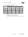
Revision History
Date
Revision
May 2001
Revise layout.
July 2001
Update for V.92
Information in this document is provided in connection with Intel products. No license, express or implied, by estoppel or otherwise, to any intellectual
property rights is granted by this document. Except as provided in Intel’s Terms and Conditions of Sale for such products, Intel assumes no liability
whatsoever, and Intel disclaims any express or implied warranty, relating to sale and/or use of Intel products including liability or warranties relating to
fitness for a particular purpose, merchantability, or infringement of any patent, copyright or other intellectual property right. Intel products are not
intended for use in medical, life saving, or life sustaining applications.
Intel is a trademark or registered trademark of Intel Corporation or its subsidiaries in the United States.
Intel may make changes to specifications and product descriptions at any time, without notice.
Designers must not rely on the absence or characteristics of any features or instructions marked "reserved" or "undefined." Intel reserves these for
future definition and shall have no responsibility whatsoever for conflicts or incompatibilities arising from future changes to them.
The MD566X may contain design defects or errors known as errata which may cause the product to deviate from published specifications. Current
characterized errata are available on request.
Contact your local Intel sales office or your distributor to obtain the latest specifications and before placing your product order.
Copies of documents which have an ordering number and are referenced in this document, or other Intel literature may be obtained by calling 1-800548-4725 or by visiting Intel’s website at http://www.intel.com.
Copyright © Intel Corporation, 2001
*Third-party brands and names are the property of their respective owners.
2
Intel Confidential
Programmer’s Guide
56K V.92 Data, Fax, and Voice Chipset
CONVENTIONS
This section lists conventions used in this data book.
Note:
S-registers and AT commands are in bold typeface throughout this document.
Abbreviations
Symbol
Units of measure
°C
degree Celsius
µF
microfarad
µs
microsecond (1,000 nanoseconds)
Hz
hertz (cycle per second)
K (memory)
kilobit (1,024 bits)
kbits/second
kilobit (1,000 bits) per second
kHz
kilohertz
kΩ
kilohm
Mbyte (memory)
megabyte (1,048,576 bytes)
MHz
megahertz (1,000 kilohertz)
mA
milliampere
ms
millisecond (1,000 microseconds)
ns
nanosecond
pV
picovolt
V
volt
W
watt
Acronyms
Acronym
Definition
AC
alternating current
AT
‘Attention’ command prefix for Hayes AT∗ command
set (for example, ‘ATDT 123’)
CMOS
complementary metal-oxide semiconductor
DC
direct current
DAA
data access arrangement
Programmer’s Guide
Intel Confidential
3
56K V.92 Data, Fax, and Voice Chipset
Acronyms
Acronym
DRAM
EPROM
dynamic random-access memory
electrically programmable read-only memory
FIFO
first in/first out
HDLC
high-level data link control
ISA
industry standard architecture
LSB
least-significant bit
MSB
most-significant bit
NVRAM
non-volatile random-access memory
PPP
point-to-point protocol
RAM
random-access memory
ROM
read-only memory
R/W
read/write
SDLC
synchronous data link control
SQFP
shrink quad flat pack
SRAM
static random-access memory
TTL
4
Definition (Continued)
transistor-transistor logic
UART
universal asynchronous receiver transmitter
VQFP
very-tight-pitch quad flat pack
Intel Confidential
Programmer’s Guide
56K V.92 Data, Fax, and Voice Chipset
1. INTRODUCTION
The MD566X Programmer’s Guide describes the software interface of Intel’s V.90/V.92 56K
solution. The programmer’s guide includes the AT command sets for data, fax, and voice and the
16C450/16C550A UART emulation. The programmer’s guide should be used with the following
Intel publications: the MD566X Datasheet, the IS-101 Voice Application Note, and the Class 1 Fax
Application Note. Please note that supported AT commands are firmware revision-dependent.
IMPORTANT: The AT commands in this document are supported by firmware versions
6.06 and above for V.90 and 7.XX for V.92.
Like the earlier solutions from Intel, the V.90/V.92 56K family of products supports a variety of
applications without the need of additional firmware development. The MD566X solutions
described in Table 1-1 are currently available except as noted.
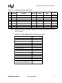
Table 1-1.
Chipset
Intel® V.90/V.92 56K Chipsets
Contents (Qty)
Notes
MD5660AM-S101
MD4450C-SC-B (1)
MD5660T-M-A (1)
MD1724-11VC-B (1)
Data, Fax, Voice
Parallel/Serial (RS232) interfaces
MD5661AM-V101
MD4451C-VC-B (1)
MD5661DT-L-A (1)
MD1724-11VC-B (1)
Data, Fax, Voice
PCMCIA interface
MD5662AM-S101
MD4450C-SC-B (1)
MD5660DT-M-A (1)
MD1724-11VC-B (2)
Data, Fax, Voice, Speakerphone
Parallel/Serial (RS232) interfaces
MD5663AM-V101
MD4450C-SC-B (1)
MD5661DT-L-A (1)
MD1724-11VC-B (1)
Data, Fax, Voice
MD5664GL-V101
MD4452C-VC-B (1)
MD5661DT-L-A (1)
S13014 (1)
S13021 (1)
CompactFlash
Data, Fax
MD5664US-V101
MD4452C-VC-B (1)
MD5661DT-L-A (1)
S13012 (1)
S13021 (1)
CompactFlash
Data, Fax
Programmer’s Guide
Intel Confidential
5
56K V.92 Data, Fax, and Voice Chipset
1.1 V.92, V.90 and V.34 Data Modes
Intel® MD566X chipsets default to the ITU-T V.90 or V.92 data transmission mode depending on
the firmware version. The V.90/V.92 mode allows receive data rates of up to 56 kbps over the
PSTN (public switched telephone network) only in connections with equipment-compatible ISPs
(Internet Service Providers); however, FCC regulations limit receive speeds to 53,333 kbps due to
excessive power demands at higher speeds. In modem-to-modem connections V.90/V.92 mode falls
back to the V.34 mode in both the transmit and receive directions.
1.2 Modem Connection Overview
The DCE (modem) operates in one of two states: command or online. In each state, both data and
commands (including DCE responses) are transferred through the UART THR (Transmit Holding
register) and the RBR (Receiver Buffer register).
The modem defaults to the command state. In the command state, the DTE (host) communicates to
the modem through AT commands and S-registers. AT commands are character strings that help
guide modem operation. S-registers are internal modem registers that the DTE can access. The Sregisters contain modem status and configuration information. Many of the AT commands
indirectly affect the contents of the S-registers. The MD566X’s AT command set and S-registers
are divided into the following modes: Group 3 fax, data, V.42/MNP, voice. See Chapter 2 on page 8
for command table summaries.
All command lines sent to the modem, except for A/, must be preceded by an ‘AT’ (which stands
for ‘attention’) and terminated by the contents of S-register S3 (typically a carriage return <CR>).
The ‘AT’ prompts the modem to receive a command line from the DTE. A <CR> informs the
modem that the entire command string has been transmitted and that the modem should start
processing all the commands within the command line.
A command line may include one or more AT commands that may or may not be separated by a
space. AT commands may be either upper- or lower-case characters, but all characters for a given
command must use the same case. If there are multiple commands in a line, a semicolon (;) must be
placed after each fax or voice command. The modem can be configured to send back (echo) to the
DTE any data that the DTE sends to the modem (while in command state only). The last command
may be repeated by typing A/ without using a carriage return. Each command line may include up
to 80 characters and spaces.
Examples of AT command strings:
ATS1?<CR>
A/
AT &C1 &D2 +FCLASS=? <CR>
AT &C1 &D2 +FCLASS=?; S0=1 <CR>
The modem provides status information to the DTE in the form of response codes. These response
codes can be expressed in text or numeric form. The supported response codes for V.90 mode are
provided in Table 2-10 on page 21 and V.34 response codes are included in Table 2-11 on page 22.
6
Intel Confidential
Programmer’s Guide
56K V.92 Data, Fax, and Voice Chipset
Examples of modem responses:
OK
ERROR
CONNECT 28800
0
In the online state, the DCE is off-hook and communicating with a remote modem. Any data sent
from the DTE to the DCE is transmitted to the remote modem. Similarly, any data that the DCE
receives from the remote modem is transmitted to the DTE.
Note:
In the online state, the DCE does not ‘echo-back’ any of the data that the DTE sent to the DCE.
The modem recognizes AT commands from the DTE at any valid data rate from 300 bps to 115,200
bps (that is, the modem autobauds up to 115,200 bps); however, the DTE should use the data rate
specified for each mode according to the transmitting direction — DTE-to-modem (Table 1-2) or
modem-to-modem (Table 1-3).
Table 1-2.
DTE-to-DCE Data Rates for Each Mode
Mode
Data Rate (bps)
Data (V.34)
Data (V.90)
Data (V.92)
Fax
2400–115,200
28,800–115,200
28,800–115,200
19,200
Voice
19,200–115,200
Table 1-3.
Affected Data
DTE-to-modem data rate
AT commands, playback and record modes
(varies according to compression type)
DCE-to-DCE Data Rates for Each Mode
Mode
Data (V.34)
transmit and receive
Data (V.90) transmit
Data (V.90) receive
(ISP connections only)
Data (V.92) transmit
Data (V.92) receive
(ISP connections only)
Fax
Voice
Data Rate (bps)
Affected Data
2400–33,600
4800–33,600
28,800–56,000
DTE-to-modem data rate
24,000–48,000
28,800–56,000
2400–14,400
Not applicable
Not applicable
Each command may have one or more parameters associated with it. If a parameter is not sent for a
command requiring a numeric parameter, then the modem assumes a zero (“0”) parameter (only if
zero is a valid parameter for the command). For example, ATZ and ATZ0 commands perform
identical functions (that is, the modem sees ‘ATZ’ and automatically uses the ‘0’ parameter during
processing the command). Other commands do not use parameters.
Programmer’s Guide
Intel Confidential
7
56K V.92 Data, Fax, and Voice Chipset
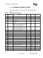
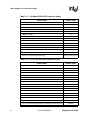
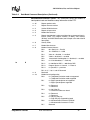
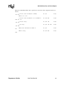
2. AT COMMAND SUMMARY TABLES
This section contains summary tables of all AT commands, S-registers, and manufacturing-only
commands. These commands are described fully in the relevant sections of the Programmer’s
Guide.
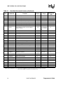
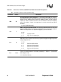
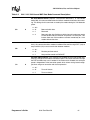
Table 2-1.
Note
**
*
Data Mode Command Summary
Command
Range
Reported by
&Vn
Repeat last command
none
–
no
A
Answer
none
–
no
Bn
Select ITU-T or Bell*
1
0–3
yes
1
0, 1
no
B0
Selects ITU-T V.22 at 1200 bps and ITU-T
V.21 at 300 bps
B1
Selects Bell 212A at 1200 bps and Bell 103J
at 300 bps
B2
Selects ITU-T V.23 only. The originating
modem transmits at 75 bps (and receives at
1200 bps); the answering modem receives at
75 bps (and transmits at 1200 bps)
B3
Selects ITU-T V.23 only. The originating
modem transmits at 1200 bps (and receives
at 75 bps); the answering modem receives at
1200 bps (and transmits at 75 bps)
Carrier control option
C0
C1
Transmit carrier always off
Normal transmit carrier
D
Dial command
none
–
no
En
Command mode echo
1
0, 1
yes
1
0, 1
no
0
0, 1
no
0
0–8, 10, 11,
14, 20–23
no
E0
E1
Fn
Disables echo
Enables echo
Online echo
F0
Enables online echo
F1
Disables online echo
Hn
Switch hook control
H0
Hangs up the telephone line
H1
Picks up the telephone line
In
8
Default
A/
Cn
*
Function
Identification/checksum option
I0
Reports product code
I1
Reports modem chip firmware version
I2
Verifies ROM checksum
I3
Reports chipset name
Intel Confidential
Programmer’s Guide
56K V.92 Data, Fax, and Voice Chipset
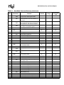
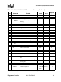
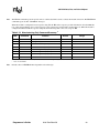
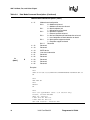
Table 2-1.
Note
*
*
*
Data Mode Command Summary (Continued)
Command
Function
I4
Reserved
I5
Reserved for modem chip hardware configuration
I6
Country code
I7
Version of board manufacturer firmware
I8
Modem firmware features
I10
Modem board configuration — bits set by
board manufacturer
I11
Modem board configuration — bits set by
board manufacturer
I12
Reserved
I13
Reserved
I14
SAFE device
I20
Intel silicon version
I21
Intel firmware version
I22
Intel manufacturer name
I23
Intel product model
Ln
Speaker volume control
L0
Low speaker volume
L1
Low speaker volume
L2
Medium speaker volume
L3
High speaker volume
Mn
Speaker control
M0
Speaker always off
M1
Speaker on until carrier present
M2
Speaker always on
M3
Speaker off during dialing; speaker on until
carrier present
Nn
Select data rate handshake
N0
Handshake only at DTE-to-modem data rate
N1
Begins handshake at DTE-to-modem data
rate and falls to highest compatible rate
On
Go online
O0
Returns modem to Data mode
O1
Retrains equalizer and then returns to Data
mode
Default
Range
Reported by
&Vn
1
0–3
yes
1
0–3
yes
1
0, 1
yes
0
0, 1
no
*
P
Select pulse dialing
none
–
yes
*
Qn
Result code display control
0
0, 1
yes
Q0
Programmer’s Guide
Enables result codes
Intel Confidential
9
56K V.92 Data, Fax, and Voice Chipset
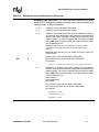
Table 2-1.
Note
Data Mode Command Summary (Continued)
Command
Q1
Sn
Default
Range
Reported by
&Vn
Disables result codes
Select an S-register
Sn=x
Write to an S-register
none
0–37
no
none
n=0–37
x=0–255
no
Sn?
Read from an S-register
none
0–33
no
*
T
Select tone dialing
none
–
no
*
Vn
Result code form
1
0, 1
yes
0
0, 2–4
yes
4
0–4
yes
0
0, 1
yes
0
0, 1
no
1
0, 1
yes
2
0–3
yes
V0
V1
*
*
*
Wn
*
Choose verbose (text) form
W0
Reports DTE speed response codes
W2
Reports DCE speed response codes
W3
Reports DTE speed response codes and
information on error correction and data compression
W4
Reports protocol, data compression, and DTE
data rate
X0
Enables result codes 0–4; disables detection
of busy and dial tone
X1
Enables result codes 0–5, 10, and above; disables busy and dial tone detection
X2
Enables result codes 0–6 and 10 and above;
disables busy detection and enables dial tone
detection
X3
Enables result codes 0–5, 7, and 10 and
above; enables busy detection and disables
dial tone detection
X4
Enables result codes 0–7 and 10 and above;
enables busy and dial tone detection
Xn
Result code type
Yn
Long space disconnect
Y0
Disables long space disconnect
Y1
Enables long space disconnect
Recall stored profile
Z0
Resets modem and recalls user profile 0
Z1
Resets modem and recalls user profile 1
&Cn
&Dn
Choose numeric form
Response code data rate
Zn
10
Function
DCD (data carrier detect) option
&C0
Ignores remote modem status; DCD always
on
&C1
DCD set according to remote modem status
DTR (data terminal ready) option
Intel Confidential
Programmer’s Guide
56K V.92 Data, Fax, and Voice Chipset
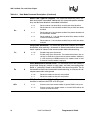
Table 2-1.
Note
*
Data Mode Command Summary (Continued)
Command
Function
&D0
In Async mode, modem ignores DTR
&D1
Modem switches from data mode to command mode when an on-to-off transition of
DTR occurs
&D2
When DTR switches off, the modem goes onhook and disables Auto-answer mode; when
DTR switches on, auto-answer is enabled
&D3
Turning off DTR re-initializes the modem and
resets values except UART registers
Default
Range
Reported by
&Vn
&F
Load factory defaults
none
–
no
&Gn
Guard tone option (1200 bps and 2400 bps
only)
0
0–2
yes
3
0, 3, 4
yes
&G0
Disables guard tone
&G1
Enables 550-Hz guard tone
&G2
Enables 1800-Hz guard tone
&Kn
Select serial flow control
&K0
Disables flow control
&K3
Bidirectional hardware flow control
&K4
XON/XOFF software flow control
*
&M0
Communication mode option — modem supports only Async mode
0
0
no
*
&Pn
Dial pulse ratio
0
0, 1
yes
Communication mode option — modem supports only Async mode
0
0
yes
DSR (data set ready) option
0
0, 1
yes
0
0, 1, 8
no
0
0, 1
yes
0
0, 1
no
*
&Q0
*
&Sn
&P0
Sets 10-pps pulse dial with 39%/61% makebreak
&P1
Sets 10-pps pulse dial with 33%/67% makebreak
&S0
DSR is always active
&S1
DSR active only during handshaking and
when carrier is lost
&Tn
Self test commands
&T0
Terminates test in progress
&T1
Initiates local analog loopback
&T8
*
&Un
Initiates local analog loopback with self-test
Disable Trellis coding
&U0
Enables Trellis coding with QAM as fallback
&U1
QAM modulation only
&V0
View active profile and stored profile 0
&V1
View active profile and stored profile 1
&Vn
View active and stored profiles
Programmer’s Guide
Intel Confidential
11
56K V.92 Data, Fax, and Voice Chipset
Table 2-1.
Note
Data Mode Command Summary (Continued)
Command
&Wn
*
Stored active profile
&W0
Store in user profile 0
&W1
Store in user profile 1
&Yn
*
*
Select stored profile on power up
&Y0
Recall stored profile 0 on power-up
&Y1
Recall stored profile 1 on power-up
Default
Range
Reported by
&Vn
0
0, 1
no
0
0, 1
yes
&Zn=x
Store telephone number (up to 30 digits) to
location “n” (0–3)
none
n = 0–3
x = 0–9 A B C
D#*TPRW
@,!;
no
%En
Auto-retrain control
1
0, 1
yes
1
0, 1
yes
0
0–2
yes
%E0
Disables auto-retrain
%E1
Enables auto-retrain
%Gn
*
Function
Rate renegotiation
%G0
Disabled
%G1
Enabled
-Cn
Generate data mode calling tone
-C0
Calling tone disabled
-C1
1300-Hz calling tone enabled
-C2
V.8 calling tone and 1300-Hz calling tone
+GMI?
Identify modem manufacturer
none
–
no
+GMM?
Identify product model
none
–
no
+GMR?
Identify product revision
none
–
no
+MS=m
Modulation selections
V90, 1,
0, 0
See note a
no
+PCW=m
Call waiting enable
0
0, 1, 2
no
+PMH=m
Modem on hold enable
0
0, 1
no
+PMHT=m
Modem on hold timer
0
0 - 13
no
+PMHR
Initiate modem on hold
none
0 - 13
no
+PIG=m
PCM upstream ignore
0
0, 1
no
+PMHF
V.92 modem on hold hook flash
none
+PQC=m
V.92 phase 1 and phase 2 control
0
0, 1, 2, 3
no
+PSS=m
Use short sequence
2
0, 1, 2
no
no
a. See the +MS=m description on Table 3-4 of the MD566X Programmer’s Guide for a full command description of parameter ranges. For Data mode, the factory
default setting is AT+MS=V90, 1, 0, 0 to send at speeds of 33,600 bps or below and receive at speeds of 53,333 bps and below.
*
12
Value saved in NVRAM. **Command not preceded by an “AT”.
Intel Confidential
Programmer’s Guide
56K V.92 Data, Fax, and Voice Chipset
Programmer’s Guide
Intel Confidential
13
56K V.92 Data, Fax, and Voice Chipset
V.44 / V.42 / V.42 bis MNP∗ Command Summary
Table 2-2.
Note
Command
*
%An
*
%Cn
*
Function
Range
Reported
by &Vn
Set auto-reliable fallback character
13
0–127
yes
MNP 5 data compression control
1
0, 1
yes
3
0–3
yes
%C0
No compression
%C1
Enables MNP5 data compression
\An
Default
MNP block size
\A0
Maximum 64 characters
\A1
Maximum 128 characters
\A2
Maximum 192 characters
\A3
Maximum 256 characters
*
\Bn
Transmit break
none
0–9
no
*
\Cn
Set auto-reliable buffer
0
0–2
yes
0
0, 1
yes
0
0, 1
yes
5
0–5
yes
*
*
*
\C0
No data buffering
\C1
Four-second buffer until 200 characters in
the buffer or detection of a SYN character
\C2
No buffering. Connects non-V.42 modems
to V.42 modem
\Gn
Set modem port flow control
\G0
Disables port flow control
\G1
Sets port flow control to XON/XOFF
\Jn
bps rate adjust control
\J0
Disables rate adjust
\J1
Enables rate adjust
\Kn
Set break control
In connect state, transmits break to remote (if in Reliable mode):
\K0, 2, 4
Enters Command mode, no break sent
\K1
Destructive/expedited
\K3
Nondestructive/expedited
\K5
Nondestructive/nonexpedited
In command state, transmits break to remote (if in Reliable mode):
\K0, 1
Destructive/expedited
\K2, 3
Nondestructive/expedited
\K4, 5
Nondestructive/nonexpedited
In connect state, receives break at modem port (if in Direct mode):
\K0, 2, 4
Immediately sends break and enters command state
\K1, 3, 5
Immediately sends the break through
In connect state, receives break at modem port and sends to serial port:
\K0, 1
14
Destructive/expedited
Intel Confidential
Programmer’s Guide
56K V.92 Data, Fax, and Voice Chipset
V.44 / V.42 / V.42 bis MNP∗ Command Summary (Continued)
Table 2-2.
Note
Command
\K2, 3
\K4, 5
*
*
*
*
*
*
\Nn
Function
Default
Range
Reported
by &Vn
Nondestructive/expedited
Nondestructive/nonexpedited
Set operating mode
\N0, \N1
Selects Buffer (Normal) mode with speed
buffering
\N2
Selects MNP Reliable mode
\N3
Selects V.42 Auto-reliable mode
\N4
Selects V.42 Reliable mode
3
0–4
yes
\O
Originate reliable link
none
–
no
\Qn
Set serial port flow control
3
0–3
yes
\Q0
Disables flow control
\Q1
XON/XOFF software flow control
\Q2
Unidirectional hardware flow control
\Q3
Bidirectional hardware flow control
\T0
Disables inactivity timer
0
0–90
yes
\U
Accept reliable link
none
–
no
Set XON/XOFF pass-through
0
0, 1
yes
\Xn
\X0
Processes flow control characters
\X1
Processes flow control characters and
passes to local or remote
\Y
Switch to Reliable mode
none
–
no
\Z
Switch to Normal mode
none
–
no
-Jn
Set V.42 detect phase
1
0, 1
yes
3
0–3
yes
V.42 bis string length
32
6–250
yes
V.44 data compression
3,0,0,
471,942,
140,140, See note a
1884,
3768
-J0
Disables the V.42 detect phase
-J1
Enables the V.42 detect phase
"Hn
V.42 bis compression control
“H0
Disables V.42 bis
“H1
Enables V.42 bis only when transmitting
data
“H2
Enables V.42 bis only when receiving data
“H3
Enables V.42 bis for both transmitting and
receiving data
"On
+DS44=m
no
a. See the +DS44=m description in Table 3-4 for a full command description of parameter ranges.
Programmer’s Guide
Intel Confidential
15
56K V.92 Data, Fax, and Voice Chipset
*
16
Value saved in NVRAM.
Intel Confidential
Programmer’s Guide
56K V.92 Data, Fax, and Voice Chipset
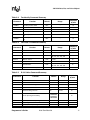
Table 2-3.
Fax Identity Command Summary
Command
Function
Default
Range
Reported
by &Vn
+FMDL?
Identifies product model
none
–
no
+FMFR?
Identifies modem manufacturer
none
–
no
+FMI?
Identifies modem manufacturer
none
–
no
+FMM?
Identifies product model
none
–
no
+FMR?
Identifies product version number
none
–
no
+FREV?
Identifies product version number
none
–
no
Range
Reported
by &Vn
Table 2-4.
Fax Class 1 Command Summary
Command
Function
Default
+FCLASS=1
Mode selection
0
0, 1, 8
no
+FRH=n
Receive HDLC data
none
3
no
Receive data
none
24, 48, 72, 73, 74, 96, 97,
98, 121, 122, 145, 146
no
+FRS=n
Wait for silence
none
1–255
no
+FTH=n
Transmit HDLC data
none
3
no
Transmit data
none
24, 48, 72, 73, 74, 96, 97,
98, 121, 122, 145, 146
no
Stop transmission and pause
none
0–255
no
+FRM=n
+FTM=n
+FTS=n
Table 2-5.
IS-101 Voice Command Summary
Command
Function
Default
Range
Reported
by &Vn
+FCLASS=8
Voice mode selection
0
0, 1, 8
no
+FLO=n
Flow Control Select
1
0–2
no
+VBT=m
Buffer threshold setting
192, 320
192, 320
no
+VCID=n
Caller ID selection
0*
0–2
no
Distinctive Ring selection
0,0
0–255,
0–255
no
–
no
+VDR=m
+VEM=m
Event reporting and masking
‘C’
BB860980
BFE63883
BB863EE0
+VGM=n
Speakerphone microphone gain
128
121–131
no
+VGR=n
Receive gain selection
128
121–131
no
+VGS=n
Speakerphone speaker gain
128
121-131
no
Programmer’s Guide
Intel Confidential
17
56K V.92 Data, Fax, and Voice Chipset
Table 2-5.
+VGT=n
IS-101 Voice Command Summary (Continued)
Volume selection
128
121–131
no
+VIP
Initialize parameter
–
–
no
+VIT=n
DTE/DCE inactivity timer
0
0–255
no
+VLS=n
Relay/speaker control
0
0–16
no
+VNH=n
Automatic hang-up control
0
0–2
no
+VRA=n
Ringback-goes-away timer
50
0–50
no
+VRN=n
Ringback-never-appeared timer
10
0–255
no
+VRX
Record mode
none
–
no
+VSD=m
Silence detection (quiet and silence)
128, 50
See note
no
Compression method selection
140, 8000, 0,
0
See note
no
Speakerphone on/off control
0
0, 1
no
+VSM=m
+VSP=n
#VSPS=n
Speakerphone type selection
1
0, 1
no
+VTD=n
Beep tone duration timer
100
5–255
no
+VTS=m
DTMF and tone generation
none
See note
no
+VTX
Play mode
none
–
no
NOTE: See the complete command description in the MD566X Programmer’s Guide for range
information.
* The noted parameters, commands, and responses depend on the capability to receive.
Table 2-6.
Response
<NUL>
Hex Code
Function
00
Do nothing
10
Two contiguous <DLE><DLE> codes indicate a single
<DLE> in the data stream
<SUB>
1A
<DLE><DLE> in data stream
<ETX>
03
End transmit data state
/
2F
Start of DTMF tone shielding
<DEL>
7F
DTMF transition to off
<DLE>
18
Voice DTE→DCE Character Pairs
u
75
Bump up the volume
d
64
Bump down the volume
<ESC>
1B
End receive data state
!
21
Receive data abort
<CAN>
18
Clear transmit buffer of voice data
?
3F
Transmit buffer space available query
Intel Confidential
Programmer’s Guide
56K V.92 Data, Fax, and Voice Chipset
Table 2-7.
Response
Voice DTE←DCE Character Pairs
Hex Code
Function
<DLE>
10
Single <DLE> character in the data stream
<SUB>
1A
<DLE><DLE> in data stream
<ETX>
3
End of Record mode data
X
58
Packet header for ‘Complex Event Detection Report’
.
2E
Packet terminator for the ‘Complex Event Detection
Report’
/
2F
Start of DTMF tone shielding
<DEL>
7F
DTMF transition to off
0–9
30–39
DTMF tones 0–9
A–D
41–44
DTMF tones A–D
*
2A
DTMF tone *
#
23
DTMF tone #
o
6F
Receive buffer overrun
c
63
1100-Hz fax calling tone
e
65
1300-Hz data calling tone
h
68
Local phone goes on hook
H
48
Local phone goes off hook
s
73
Presumed hang-up silence time-out
q
71
Presumed end-of-message quiet time-out
I
6C
Loop current interruption
L
4C
Loop current polarity reversal
r
72
Ringback
b
62
Busy/reorder/fast busy
d
64
Dial tone detected
u
75
Transmit buffer under-run
p
70
Line voltage increase (extension phone goes on-hook)
P
50
Line voltage decrease (extension phone goes off-hook)
a
61
Fax or data answer tone (2100 Hz)
f
66
Data answer detected (2225 Hz)
R
52
Incoming ring
% ‘ (,)
25, 26, 27,
Manufacturer-specified
28, 29
Programmer’s Guide
Intel Confidential
19
56K V.92 Data, Fax, and Voice Chipset
Table 2-8.
Dial Modifiers
Command
Function
0 to 9
Note:
Dialing digits
A, B, C, D, *, #
Tone dial characters
P
Pulse dial
R
Reverse Originate mode
S=n
Dial NVRAM telephone number
T
Tone dial
W
Wait for dial tone
,
Pause
!
Flash hook
@
Wait for quiet answer
;
Return to command state
-()
Ignored by modem
L
Redial last number
The manufacturing-only S-registers S91 and S92 are listed in the Manufacturing-Only Commands in
Table 2-13 on page 23.
* Value saved in NVRAM.
Table 2-9.
Note
*
Register
Function
Default
Range
Units
Reported
by &Vn
S0
No. of rings to auto-answer on
0
0–255
ring
yes
S1
Ring count
0
0–255
ring
yes
S2
Escape character
43
0–127
ASCII
yes
S3
Carriage return character
13
0–127
ASCII
yes
S4
Line feed character
10
0–127
ASCII
yes
S5
Backspace character
8
0–32, 127
ASCII
yes
*
S6
Wait before dialing
2
2–255
second
yes
*
S7
Wait for carrier
60
1–255
second
yes
*
S8
Pause time for dial modifier
2
0–255
second
yes
*
S9
Carrier recovery time
6
1–255
0.1 second
yes
*
S10
Lost carrier hang up delay
14
1–255
0.1 second
yes
*
S11
DTMF dialing speed
70
50–255
ms
yes
*
S12
Guard Time
50
0–255
(0.02 second)
yes
*
S14
Bit-mapped options
138
–
–
no
S16
Modem test options
0
–
–
no
*
S18
Modem test timer
0
0–255
second
yes
*
S21
Bit-mapped options
48
–
–
no
*
20
S-Register Summary
Intel Confidential
Programmer’s Guide
56K V.92 Data, Fax, and Voice Chipset
Table 2-9.
Note
S-Register Summary (Continued)
Register
Function
*
S22
Bit-mapped options
*
S23
Bit-mapped options
*
S25
Detect DTR change
*
S27
Bit-mapped options
*
S30
*
*
*
Default
Range
Reported
by &Vn
–
–
no
none
–
–
no
5
0–255
0.01 second
yes
64
–
–
no
Disconnect inactivity timer
0
0–255
minute
yes
S31
Bit-mapped options
49
–
–
no
S33
Sleep mode timer
10
0–90
second
yes
S37
Maximum line speed attempted
0
0–35
–
yes
Note:
118
Units
The manufacturing-only S-registers S91 and S92 are listed in the Manufacturing-Only Commands
in Table 2-13 on page 23.
* Value saved in NVRAM.
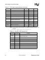
Table 2-10. V.90/V.92 Mode DCE-to-ISP Response Codes
Verbose Code
Numeric Code
CONNECT 33333
33
CONNECT 37333
34
CONNECT 41333
35
CONNECT 42667
36
CONNECT 44000
37
CONNECT 45333
38
CONNECT 46667
39
CONNECT 48000
42
CONNECT 49333
43
CONNECT 50667
53
CONNECT 52000
54
CONNECT 53333
55
CONNECT 54666
56
CONNECT 56000
57
CONNECT (DTE protocol) / data
compression / TX:(DCE transmit data
rate) / RX:(DCE receive data rate)
Programmer’s Guide
See Note following
Table 2-12 on page 23
Intel Confidential
21
56K V.92 Data, Fax, and Voice Chipset
Table 2-11. V.34 Mode DCE-to-DCE Response Codes
Verbose Code
Numeric Code
CONNECT 2400
10
CONNECT 4800
11
CONNECT 7200
24
CONNECT 9600
12
CONNECT 12000
25
CONNECT 14400
13
CONNECT 16800
59
CONNECT 19200
14
CONNECT 21600
61
CONNECT 24000
62
CONNECT 26400
63
CONNECT 28800
64
CONNECT 31200
65
CONNECT 33600
66
CONNECT (DTE protocol) / data compression / TX:(DCE transmit
data rate) / RX:(DCE receive data rate)
See Note following
Table 2-12 on page 23
Table 2-12. DTE-to-DCE Data Rate Response Codes
Verbose Code
Numeric Code
OK
0
CONNECT
1
RING
2
NO CARRIER
3
ERROR
4
NO DIAL TONE
6
BUSY
7
NO ANSWER
8
CONNECT 1200
5
CONNECT 2400
10
CONNECT 4800
11
CONNECT 9600
12
CONNECT 19200
14
CONNECT 38400
28
CONNECT 57600
18
CONNECT 115200
31
CONNECT (DTE data rate) /(modulation)/(error correction)/(data compression) / TX:(DCE transmit data rate) / RX:(DCE receive data rate)
22
Intel Confidential
See Note
Programmer’s Guide
56K V.92 Data, Fax, and Voice Chipset
Note:
The W3 AT command reports the special verbose code listed, which is used to evaluate the modem connection. The W0–W2 AT
commands report all other ‘CONNECT’ messages.
When the modem is configured for text responses using V1, the W3 verbose response provides information about the DTE data
rate, connection modulation, error correction protocol, data compression, and modem-to-modem data rate. When the modem is
configured for W3 and numeric responses using V0, the modem responds as if it were set up for W0.
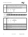
Table 2-13. Manufacturing-Only Command Summary a
Note
*
Command
Function
Default
Range
*NCnn
Country Select
0
–
!P=m
Set plug-and-play board serial number
none
0–255, 0–255, 0–255, 0–255
*
S91
Select transmit level (-dBm)
10
0–15
*
S92
DTMF transmit level (-dBm)
10
0–15
#VGP0=n
Read/write to general-purpose pins 0–7
See note
–
#VGP1=n
Read/write to general-purpose pins 8–15
See note
–
#VGP2=n
Read/write to general-purpose pins 16–23
See note
–
%TTnn
Tone test
00
–
a. These commands are meant to be used by the board manufacturer and not in generic applications software for end users.
*
Note:
Value saved in NVRAM.
Default values for #VGP0–2 =n are dependent on board design.
Programmer’s Guide
Intel Confidential
23
56K V.92 Data, Fax, and Voice Chipset
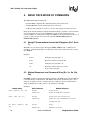
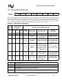
3. BASIC DATA MODE AT COMMANDS
The 56K FastPath chipsets implement:
• Standard TIES-compatible AT commands and S-registers in data mode
• Standard EIA/TIA-578 AT commands in Class 1 fax mode
• Additional AT command sets for error correction, data compression and voice mode
In data mode, the AT commands configure the DCE (modem) to establish a connection with a
remote data modem. In data mode, the MD566X executes the AT commands for error
correction (MNP 2-4, V.42) and data compression (MNP 5, V.42 bis) described in Table 4-2 on
page 66, as well as the fax and voice mode commands AT+FCLASS=1 (fax) and
AT+FCLASS=8 (voice).
3.1 Using AT Commands to Access the S-Registers [Sn?, Sn=x,
?]
The DTE can access the S-registers through the ATSn?, ATSn=x, and ? commands. For
example, to configure the modem to automatically answer a data modem call after two rings,
type ATS0=2.
Examples:
ATS0=2
Configures S-register S0 to “2”
ATS0?
Reads the contents of S-register S0
ATS0=
Configures S-register S0 to “0”
AT?
Reads the contents of the last accessed
(read or write) S-register
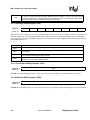
3.2 Modem Responses and Command Echo [En, Vn, Xn, Wn,
Qn]
The ATEn command configures the DCE to send back to the DTE any data that the DTE sent
to the DCE while in command mode. The ATVn command sets the DCE response codes to
either text or numeric form. For example, upon successfully processing an AT command
string, the DCE sends an “OK” (text) or a “0” (numeric) to the DTE.
Examples:
Modem Setup
Host Command
Modem Response
Echo, Numeric (E1, V0)
AT<CR>
ATS0?<CR>
AT<CR>0<CR>
ATS0?<CR>000<CR><LF>0<CR>
Echo, Text (E1, V1)
AT<CR>
ATS0?<CR>
AT<CR><CR><LF> OK<CR><LF>
ATS0?<CR><CR><LF>000<CR><LF><CR>
<LF>OK<CR><LF>
No Echo, Numeric (E0,
V0)
24
AT<CR>
ATS0?<CR>
0<CR>
000<CR><LF>0<CR>
Intel Confidential
Programmer’s Guide
56K V.92 Data, Fax, and Voice Chipset
No Echo, Text (E0, V1)
AT<CR>
ATS0?<CR>
<CR><LF>OK<CR><LF>
<CR><LF>000<CR><LF><CR><LF>OK
<CR><LF>
Configure the DCE to use different response codes using the ATWn command (see page 49). The
setting for the ATXn command (page 50) can affect which ATWn response codes are reported to
the DCE. The ATXn command configures the modem call progress detection and reporting
requirements during dialing (for example, dial tone and busy tone detection). The ATQn command
selects whether the modem sends result codes to the DTE.
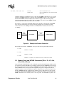
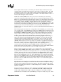
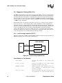
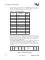
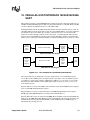
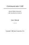
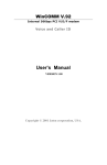
For example, a connection is established with the remote modem as shown below (with LAPM
error correction and V.42 bis data compression). The telephone line (or modem-to-modem
connection) data rate is 33,600 bps and the local UART (DTE-to-modem) connection rate is
115,200 bps.
DTE
UART
Interface
Telephone
Line
LOCAL MODEM
(115,200 bps)
(33,600 bps)
REMOTE MODEM
Figure 3-1. Example of a Remote Connection
The modem then sends the “CONNECT” messages for the following three Wn commands:
1. ATW0
CONNECT 115200
2. ATW2
CONNECT 33600
3. ATW3
CONNECT 115200/V34/LAPM/V42B/TX=33600/RX=33600
3.3 Modem Reset and NVRAM Commands [DS=n, Zn, &F, &Vn,
&Yn, &Wn, &Zn=x]
On powering-up, the DCE defaults to the configuration specified in NVRAM. The DCE may then
be configured as needed. The DTE stores the DCE configuration in the NVRAM by first setting up
the current configuration and then sending an AT&Wn command. The DCE configuration stored
in the NVRAM is called a user profile. Two independent user profile configurations and four
telephone numbers can be stored. Either user profile configuration can be used for the power-up
defaults (AT&Yn). While in command mode, the DCE can be re-initialized at any time and the
user profile changed using the ATZn command. To configure the modem to factory defaults, the
AT&F command is used. A summary of the active user profile, two NVRAM user profiles, and
Programmer’s Guide
Intel Confidential
25
56K V.92 Data, Fax, and Voice Chipset
previously-saved telephone numbers can be read from the modem using the view command,
AT&Vn. The AT&Zn=x command stores one of four telephone numbers in the NVRAM. To dial
these telephone numbers, use the ATDS=n command.
If the active profile is not stored in one of the two user profiles after setting up the modem, then the
current settings are lost when the commands ATZ or AT&F are issued or when the modem is
powered down.
Examples:
ATZ
Resets and then configures the modem to
NVRAM user profile 0.
AT&F S0=1 &W1
&Y1
&F configures the modem for factory defaults.
S0=1 configures the modem to answer after
one ring.
&W1 saves the active configuration to user
profile 1.
&Y1 configures the modem to use NVRAM user
profile 1 as the power-up defaults.
Stores a telephone number into the NVRAM as
phone number 2, which can be
re-dialed later using ATDS=2.
AT&Z2 = 9,
(408)444-5555
3.4 Modem Identification Commands [In, +FMI?, +FMR?, +FMM?,
+GMI?, +GMM?, +GMR?, +FMFR?, +FMDL?, +FREV?]
The modem provides product identification AT commands that help determine the modem’s
manufacturer, model number, and product revision. To provide flexibility with older software
application programs, the modem supports several commands that can be used to request a single
item of identification (such as a modem model number). Table 3-1 lists the commands used to
obtain product information (all identification commands are usable in data, fax, or voice mode).
Table 3-1.
Product Identification Information
AT Commands
Product
Information
ATIn Command
Data Mode
Class 1 Fax Mode
Pre-FastPath
Intel Modems
Modem
Manufacturer
ATI4/ATI7
AT+GMI?
AT+FMI?
AT+FMFR?
Model Number
ATI3
AT+GMM?
AT+FMM?
AT+FMDL?
Revision Number
ATI1
AT+GMR?
AT+FMR?
AT+FREV?
Example:
26
Intel Confidential
Programmer’s Guide
56K V.92 Data, Fax, and Voice Chipset
ATI1
Causes the modem to send the modem’s firmware
version to the DTE.
CD08.55-612 (10/19/99)PARALLEL-SPEAKERPHONE 05-DSP PATCH.001.55
Firmware version that is the modem’s response to
the command.
3.5 Establishing a Modem Connection [A, D, DS = n, S0]
Data mode provides several methods for establishing a connection with a remote modem. For each
modem, a connection can be initiated manually or automatically in both answer and originate
modes. A manual-to-manual connection is useful when both modems (that are on-hook) are
connected to an off-hook telephone line. For example, if two people are talking on the telephone,
they can manually establish a modem connection without first hanging up. When establishing a
manual connection, one modem must be designated as the originating modem and the other as the
answering modem. Manual originate mode is initiated by sending an ATD to the DCE. Manual
answer mode is accomplished by sending an ATA to the DCE.
Automatic originate mode is initiated by sending an ATD <telephone number & dial modifiers>
or ATDS=n to the DCE. Automatic-answer mode is accomplished by setting S-register S0 to a
non-zero value. S1 keeps track of how many ring signals are detected. If the content of S0 is nonzero and the number of ring signals (as defined by S0) are detected (that is, S1 = S0), then the DCE
goes off-hook and attempts to connect to the remote modem (with the following exceptions):
1) The time period between the ring signals is greater than 8 seconds, which causes
the S1 counter to reset and thus never reach the value for S0.
2) Caller ID is enabled and S0=1, the modem answers on the second ring signal
instead of the first ring signal. This happens because Caller ID puts a signal on the
telephone line between the first and second ring signal.
Example:
ATDT9,444-5555
Automatically dials the telephone number with
DTMF tones. After dialing a “9”, the comma (,)
causes the modem to pause two seconds before
dialing the rest of the telephone number.
modem 1: ATD;
When establishing a manual-to-manual connection,
the designated originating
modem should receive the ATD command from its
DTE just before the designated answering modem
receives the ATA command from its DTE.
modem 2: ATA
It is important that the time between the ATD and
ATA commands is less than 2 seconds.
AT-C1DT 123
Programmer’s Guide
Causes the modem to dial the telephone number 123
and immediately start sending a data calling tone.
Calling tone can then be detected by the remote voice
mail system. After detecting the calling tone, the
remote system can change to data mode and start the
data modem connection handshake.
Intel Confidential
27
56K V.92 Data, Fax, and Voice Chipset
3.6 Online Command Mode [Escape Codes, On]
After establishing a connection with a remote modem, the DTE sends the appropriate escape
sequence to the DCE, which causes the DCE to enter the online command mode. The online
command mode is used to send AT commands to the DCE while the DCE is still connected to the
remote modem. The supported escape sequences are described in Section 3.10. To re-enter the
online data mode, use the ATOn command.
Example:
1 second +++
1 second
Hayes Escape Sequence. Guard times (in which the
DTE does not send data to
the DCE) of 1 second are needed before and after the
three escape characters “+”.
+++AT<CR>
TIES (Time Independent Escape Sequence).
ATO
Causes the modem to re-enter online data mode.
3.7 Hanging Up [Hn, S10, Zn, &D2]
A modem connection terminates when the modem hangs up or when the remote modem transmit
carrier is off longer than the duration specified in S-register S10. To hang up, the DTE typically
sends an escape code sequence that causes the DCE to enter online command mode. Upon
receiving an “OK” message, the DTE sends either ATH or ATZn to the DCE. When the AT&D2
command is used, the modem goes on-hook (hangs up) after an on-to-off transition of the DTR
occurs.
Note:
The ATZn command causes the DCE to hang up and re-initialize itself to the user profile specified
by ‘n’.
3.8 Modem-to-Modem Connection Data Rates
The data rates differ for each data mode selected. V.90 or V.92 is the default data mode depending
on the firmware version. For non-V.90 connections the chipsets fall back to V.34 mode. The
modem defaults to whatever mode is issued by the +MS=m command (see page 56). The
supported modulation types are listed in Table 3-2 on page 33. This table includes all modulation
types and the data rates for transmitting and receiving. In Data mode, the 56K chipsets can transmit
up to 48,000 bps (V.92 mode) or 33,600 bps (V.90 mode) and receive up to 53,333bps. Note that
the chipsets are capable of achieving 56,000 bps, but power limitations by the FCC limit actual
speeds to 53,333 bps. The 56K receive data rates can be achieved only in connections with
equipment-compatible ISPs (Internet Service Providers). In V.92 mode, the MD566X supports 3
new features: Quick Connect, Modem-on-Hold and Pulse Code Modulation (PCM) Upstream.
The Quick Connect (QC) feature reduces the time it takes to make a connection to your service
provider. The modem retains information of the line conditions from your previous connection and
uses this information to bypass parts of the training sequence. As a result, this provides faster
connections. Normal V.90 connections take about 25-30 seconds. With V.92 Quick Connect, your
connect times can be up to 50% faster.
28
Intel Confidential
Programmer’s Guide
56K V.92 Data, Fax, and Voice Chipset
The V.92 Quick Connect feature is controlled by the +PSS and +PQC commands. The +PQC
command enables and disables the shorten phase 1 and or phase 2 startup procedures. The +PSS
command forces either a short or full startup procedure on the next and subsequent connections.
To enable the modem for V.92 Quick Connect, set +PSS=0 or 1 and +PQC=0. Refer to Table 3-4.
for the detailed description of these commands.
The Modem-on-Hold (MOH) feature allows you to receive an incoming voice call and stay
connected to the Internet and then return online after your conversation without having to redial.
This is very convenient where the same phone line is used for voice calls and data connections. To
receive an incoming call as described above requires that you have the Call-Waiting service from
your telephone company. In addition, the Caller ID service from your telephone company is
recommended but not required for MOH. This feature allows you to determine who is calling. The
"hold" time for your incoming call is define by your service provide. The MOH feature also allows
you put you data connection on hold and initiate a voice call and then return online after
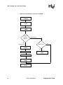
completing your voice conversation. These two scenarios are described in detail in the modem-onhold flow charts.
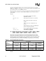
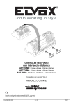
The following sequence describes how to configure the modem for MOH to process an incoming
voice call while online. First, MOH must be enabled. The +PMH and +PCW commands are used
to enable MOH and to capture the Call Waiting tone which is sent when the voice call comes in. To
enable MOH, set +PMH=0 and +PCW=0. Next, to enable Caller ID information (optional), by
setting +VCID=1. Now the modem is configured for the incoming call. When you receive the
incoming call, the modem will get a ring indication and the software/application will issue a
+++AT to put the modem in command mode. Then, you will be prompted to either "Accept" or
"Reject" the call based on the Caller ID information (if enabled). If you reject the call, an ATO
command is issued to perform a Quick Connect to stay online. If you accept the call, the data
connection is put on hold, and the modem send ad request to the server to go on hold using the
+PMHR command. The server will accept enable (1-13 returned) or reject(0 returned) the request.
If the server accepts the request to go on hold, the modem issues the +PMHF to flash the hook to
connect the call. Now you can answer the phone and talk. After completing your voice
conversation, the modem will issue another +PMHF and ATO command to initiate a Quick
Connect. If the server rejects the request to go on hold, the user can stay on line (ATO command
issued) or disconnect from his initial data connection (ATH command issued).
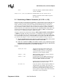
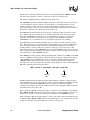
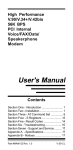
The next sequence describes how to initiate a voice call while online. First, enable the MOH
feature by setting +PMH=0. When online, the user can initiate a voice call by first issuing +++AT
to put the modem in command mode. Then request the server to go on hold by issuing the +PMHR
command. The server will either accept (1-13 returned) or reject(0 returned) the request. If the
server accepts the request to go on hold, the modem issues the +PMHF to flash the hook and get
dial tone. You can then make a voice call. After completing the voice conversation, the modem
will issue another +PMHF and ATO command to initiate a Quick Connect. If the server rejects the
request to go on hold, the user can stay on line (ATO command issued) or disconnect from his
initial data connection (ATH command issued). Refer to Table 3-4 for the detailed description of
the V.92 commands.
The PCM Upstream feature allows you to upload data to the network up to 48,000 bps. This is an
improvement over the 33,600 bps maximum with V.90. This is beneficial when you are sending
large file, e-mail attachments and gaming on the Internet. The +PIG command is used to enable
and disable the PCM Upstream feature. To enable PCM Upstream, set +PIG=0. To disable PCM
Upstream, set +PIG=1.
Several V.34 modes are available (see Table 3-2). These provide different speeds. For example,
V34B offers a modem-to-modem data rate of 2400, 4800, 7200, 9600, 12,000, 14,400, 16,800,
19,200, 21,600, 24,000, 26,400, 28,800, 31,200, and 33,600 bps. For V.42, MNP, and Buffer
(Normal) modes, the modem provides speed buffering (see Chapter 4 starting on page 63), which
Programmer’s Guide
Intel Confidential
29
56K V.92 Data, Fax, and Voice Chipset
allows the DTE-to-modem data rate to be different from the modem-to-modem data rate. Users can
take advantage of this feature by setting the DTE-to-modem rate to a high speed like 115,200 bps
and letting the modem negotiate the best line rate.
The MD566X chipsets can be configured (by the +MS=m command) to support either
asymmetrical or symmetrical connections. The modem transmits and receives at the same speed in
symmetrical connections and at different speeds in asymmetrical mode. V.90 and V.92 connections
are always asymmetrical. V.34 mode connections can be either symmetrical or asymmetrical. Note
that the transmitter speed and receiver speeds typically are different for most V.34 connections over
the PSTN.
30
Intel Confidential
Programmer’s Guide
56K V.92 Data, Fax, and Voice Chipset
Modem-on-Hold: Incoming Voice Call in Data Mode
Enable MOH
(+PMH=0)
(+PCW=0)
Enable Caller ID
(Optional)
(+VCID=1)
Incoming
Call
HW Ring Indication
(+++AT)
Accept
or
Reject
Reject Call
Accept Call
Request to go on hold
(+PMHR)
Stay Online
(ATO)
Server
Accepts
Request?
Yes
(Returns 1-13)
No (Returns 0)
Disconnect?
No
Flash Hook
(+PMHF)
Yes
Answer Call
End Data Connection
(ATH)
Finish Call
Flash Hook
(+PMHF)
Go Back Online
(ATO)
Programmer’s Guide
Intel Confidential
31
56K V.92 Data, Fax, and Voice Chipset
Modem-on-Hold: Initiating a Voice Call in Data Mode
Enable MOH
(+PMH=0)
Command Mode
(+++AT)
Request to go on hold
(+PMHR)
Server
Accepts
Request?
No (Returns 0)
Yes
(Returns 1-13)
Disconnect?
No
Flash Hook
(+PMHF)
Yes
Initiate Call
End Data Connection
(ATH)
Finish Call
Flash Hook
(+PMHF)
Go Back Online
(ATO)
32
Intel Confidential
Programmer’s Guide
56K V.92 Data, Fax, and Voice Chipset
To configure the DTE-to-modem data rate (in data on-hook command mode), change the terminal
program COM port speed selection or write the appropriate divisor latch values for a given speed
to the UART Divisor Latch registers. Then send an AT<CR> or any other valid AT command to the
modem. The modem responds with an OK at the new data rate. All commands and modem
responses that follow use the new data rate.
Note:
In command mode, the modem only changes its DTE-to-modem data rate after the Divisor Latch
register values change and the DTE sends a valid AT command.
The AT commands Bn, Nn, and +MS=m and S-register S37 define which modem-to-modem data
rates are supported by the modem. The following table shows the supported modulation types.
Each modulation supports one or more data rates.
Table 3-2.
Supported Modulation Types
<carrier >
Description
V21
V.21 300 bps
V22
V.22 1200 bps
V22B
V.22 bis 1200 and 2400 bps
V23C
V.23, with constant carrier; 1200 bps forward and 75 bps reverse
V32
V32B
V.32 4800 and 9600 bps
V.32 bis 7200, 9600, 12,000, and 14,400 bps
V34
V.34 asymmetrical connections: 2400, 4800, 7200, 9600, 12,000, 14,400, 16,800, 19,200,
21,600, 24,000, 26,400, and 28,800 bps
V34B
V.34 extended asymmetrical connections: 2400, 4800, 7200, 9600, 12,000, 14,400,
16,800, 19,200, 21,600, 24,000, 26,400, 28,800, 31,200, and 33,600 bps
V34S
V.34 symmetrical-only connections: 2400, 4800, 7200, 9600, 12,000, 14,400, 16,800,
19,200, 21,600, 24,000, 26,400, and 28,800 bps
V34BS
V.34 extended symmetrical connections: 2400, 4800, 7200, 9600, 12,000, 14,400,
16,800, 19,200, 21,600, 24,000, 26,400, 28,800, 31,200, and 33,600 bps
56K V.90 asymmetrical connections (transmit): 4800, 7200, 9600, 12,000, 14,400, 16,800,
19,200, 21,600, 24,000, 26,400, and 28,800, 31,200, and 33,600 bps
V90
56K V.90 asymmetrical connections (receive): 28,000, 29,333, 30,666, 32,000, 33,333,
34,666, 36,000, 37,333, 38,666, 40,000, 41,333, 42,666, 44,000, 45,333, 46,666, 48,000,
49,333, 50,666, 52,000 53,333, 54,666, and 56,000 bps
56K V.92 asymmetrical connections (transmit): 24,000, 25,333, 26,666, 28,000, 29,333,
30,666, 32,000, 33,333, 34,666, 36,000, 37,333, 38,666, 40,000, 41,333, 42,666, 44,000,
45,333, 46,666, 48,000 bps
V92
56K V92 asymmetrical connection (receive): 28,000, 29,333, 30,666, 32,000, 33,333,
34,666, 36,000, 37,333, 38,666, 40,000, 41,333, 42,666, 44,000, 45,333, 46,666, 48,000,
49,333, 50,666, 52,000, 53,333, 54,666, 56,000 bps
Programmer’s Guide
Intel Confidential
33
56K V.92 Data, Fax, and Voice Chipset
The allowable connection modulations and data rates are determined by the +MS=m command,
which uses four parameters: <carrier>, <automode>, <min rate>, and <max rate>.
The +MS=m <carrier> parameter defines the top modulation rate.
The <automode> parameter determines whether the modem connection is allowed to fall down to
a lower modulation rate if the connection can not be made at a specified modulation or if the
modem connection can only take place at the specified modulation. Setting <automode> to 1
allows the modem to connect at a slower <carrier> type than that specified. Setting <automode> to
0 allows the connection to use only the specified <carrier> type.
The <min rate> parameter defines the lowest data rate at which a modem connection can take
place. Setting <min rate> to 0 has one of two meanings depending on the <automode> setting.
When both <automode> and <min rate> are set to 0, then the lowest data rate at which the
connection can take place is the lowest data rate specified by the <carrier> parameter. If
<automode> is set to 1 and <min rate> is set to 0, then the lowest data rate is 300 bps.
The <max rate> parameter defines the highest data rate at which a modem connection can take
place. If the <max rate> is set to 0, the modem uses the DTE data rate or a slower <carrier> data
rate as the highest permitted connection data rate. This highest-permitted data rate means the
modem attempts to connect at this data rate but may connect at a slower rate because of line
impairment. If <max rate> and <automode> are set to 0 and the DTE data rate is below the lowest
data rate supported by the modulation rate, then the modem’s connection attempts always fail, and
the modem reports a “NO CARRIER” message.
If the +MS=m parameters contain conflicting information like “+MS=V34,1,14400,0” with a DTE
data rate of 2400 bps, then the modem’s connection attempts always fail, and the modem reports a
“NO CARRIER” message. This happens for two reasons. First, when the modem receives the
+MS=m command, the modem does not check for conflicts of valid parameter information.
Secondly, some of the same configuration information is provided by two other commands: Nn and
S37. The command issued last takes precedence.
+MS = <carrier >, <automode>, <min rate>, <max rate>
same as
Nn
same as
S37
The Nn command specifies whether the modem should attempt to establish a connection using a
single modulation type or allow the connection to fall to a lower modulation type. Nn performs the
same function as the +MS=m <automode> parameter. Whatever command is issued last
configures the modem for any following connections. Thus, upon receiving the +MS=m command,
the modem changes the value for Nn.
When configured to N0, the modem only attempts a connection at the <carrier> rate specified by
S37, +MS=m, and Bn. If the remote modem does not support any of the <carrier> data rates, the
modem does not achieve a connection and responds back with a “NO CARRIER” message.
When configured to N1, the modem attempts to connect to the remote modem at the highest speed,
as defined by S37, +MS=m, and Bn. Since not all modems support (or are configured for) the same
modem-to-modem data rates, the modems may connect at a lower speed.
34
Intel Confidential
Programmer’s Guide
56K V.92 Data, Fax, and Voice Chipset
S-register S37 specifies the maximum data rate that can be attempted during a modem connection.
If S37 is set to ‘0’, then the modem looks at the DTE rate to determine the maximum connection
data rate. If the DTE data rate doesn’t match one of the <carrier> data rates, then the modem uses
the next-fastest data rate.
The +MS command sets the modulation speeds in the MD566X chipsets; however, to set the
modulation to either V.22 or Bell 212, the B0 or B1 command also must be sent. To set the
modulation type to ITU-T V.22, send the B0 command; to set the modulation type to Bell 212, send
B1. These commands can be entered before or after the +MS command. For example, to set the
modulation to ITU-T V.22:
+MS = V22, 1, 1200, 1200; B0
It is important to remember that the ordering of commands is important in configuring the modem.
For example, if the DTE 9600 bps data rate and the AT commands are issued in the following
sequence, different connection rates result:
1. ATS37 = 0
2. AT+MS = V32B, 1, 0, 14400
AT+MS = V32B, 1, 0, 14400
ATS37 = 0
ATDT1234
ATDT1234
CONNECT 14400
CONNECT 9600
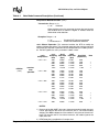
Table 3-3 shows the resulting connection data rate when using non-default values. Because of
impairments on the telephone line, the actual connection speeds may be lower than the speeds
defined in this table.
For V.92, V.90 and V.34 modulations, the modem can receive data at a different data rate than the
transmit data rate. All other modulation types besides V.23 and V.34 use the same data rate for the
transmitter and receiver. Use ATW3 to see the modem’s actual receive and transmit data rates (the
modem must be configured for ATV1 text response codes). Table 3-3 shows examples of the
resulting connection rate when non-default values are used.
Table 3-3.
Resulting DCE-to-DCE Connection Rates with Non-Default
Values
Originating
Modem
Answering
Modem
Resulting Connection Speed
+MS = V34, 1, 0, 0;
the UART data rate
= 115,200 bps
+MS = V32, 1, 0,
9600; the UART data
rate = 14,400 bps
9600 bps: the originating modem is configured
to attempt a maximum 28,800-bps connection,
but the answering modem is configured to
attempt a maximum data rate of 9600 bps.
+MS = V34, 0,
28,800, 28,800;
UART data rate =
115,200 bps
+MS = V32B, 1, 0,
9600; B1 and UART
data rate = 14,400
bps
No connection: the originating modem is configured to attempt only a 28,800 bps connection, but the answering modem is configured to
attempt a maximum data rate of 9600 bps.
+MS = V34, 1, 0,0;
UART data rate =
9600 bps
7200 bps: the originating modem is configured
to attempt connection at 7200 bps or below.
The answering modem is configured to attempt
a data rate of 9600 bps or below. The connection takes place at 7200 bps, the highest
speed supported by both modems.
N0, +MS = V32,
1, 0, 9600; S37 =
0; and UART data
rate = 7200 bps
Programmer’s Guide
Intel Confidential
35
56K V.92 Data, Fax, and Voice Chipset
3.9 Diagnostic Testing [S18, &Tn]
The &Tn command initiates loopback tests. Setting S-register S18 to a non-zero value determines
the length of testing after the modem receives the &Tn command. After the testing period elapses,
the modem halts the test and returns to command mode. To abort the test before the test timer has
timed out, enter the escape code sequence followed by AT&T0. Setting S18 to an ’0’ disables the
test timer. In this case, the loopback test continues to run until an escape code, followed by AT&T0
(or ATH), is sent to the modem.
The modem provides a local analog loopback test (see Section 3.9.1) and local analog loopback
self-test (see Section 3.9.2) for testing modem-to-modem and DTE-to-modem communication
integrity in all modes except V.90 and V.92. After entering the loopback mode, the communication
integrity is checked by the DTE sending data to the modem and then checking the looped-back data
for errors. In addition, in the self-test mode the modem implements an internal data pattern
generator and checker that detects errors. When a data error occurs in self-test mode, the modem
increments an internal error counter. Upon completing the test, the modem sends a three-digit error
count to the DTE. These tests are illustrated in the following examples.
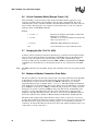
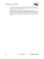
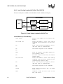
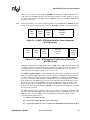
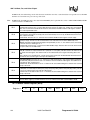
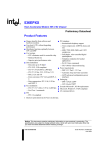
3.9.1 Local Analog Loopback [AT&T1]
This test is used by the local DTE to check the DTE-to-modem communication integrity. The local
DTE will not initiate the test from online command mode.
LOCAL MODEM
TXD
TRANSMITTER
DTE
RXD
RECEIVER
Figure 3-2. Local Analog Loopback Test
Local Modem (or Test Modem)
36
AT&F &W<CR>
Returns the modem to the factory defaults.
AT S18 = 0 &T1
Causes the modem to run local analog
loopback without self-test.
CONNECT 115200
Modem response code indicates that analog loopback is enabled with a DTE
speed of 115200.
This is a test.
Test string that the user could type at
the keyboard. If the received data is
Intel Confidential
Programmer’s Guide
56K V.92 Data, Fax, and Voice Chipset
the same as the test string, then the
DTE-to-modem communication channel is
working properly.
+++AT
TIES Escape Sequence is used to return
to command mode.
OK
Modem enters command mode.
AT&T0
Terminates any loopback test.
OK
Modem aborts analog loopback and stays
in command mode.
Programmer’s Guide
Intel Confidential
37
56K V.92 Data, Fax, and Voice Chipset
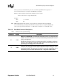
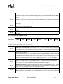
3.9.2 Local Analog Loopback With Self-Test [AT&T8]
This test is used by the local DTE to check the DTE-to-modem communication integrity.
LOCAL MODEM
TXD
PATTERN
GENERATOR
TRANSMITTER
PATTERN
CHECKER
RECEIVER
DTE
RXD
Figure 3-3. Local Analog Loopback with Self-Test
Local Modem (or Test Modem)
AT&F &W<CR>
Returns the modem to the factory defaults.
AT S18=20 &T8
Causes the modem to start local analog
loopback with self-test for 20 seconds.
OK
After starting analog loopback, the modem goes back to command mode.
AT
The modem responds to new commands.
OK
38
000
After 20 seconds, the modem stops analog loopback, sends
OK
An error count to the DTE, and enters
command mode.
AT S18=0 &T8
Causes the modem to start local analog
loopback with self-test, which is only
terminated by AT&T0 or ATH.
OK
After starting analog loopback, the modem goes back to command mode.
AT
OK
The modem responds to new commands.
AT&T0
After receiving AT&T0 or ATH, the modem
stops analog
000
loopback, sends an error count to the
DTE, and enters
Intel Confidential
Programmer’s Guide
56K V.92 Data, Fax, and Voice Chipset
OK
command mode.
3.10 AT Escape Sequences
The 56K family provides the industry-standard Time Independent Escape Sequence (TIES). The
DTE sends the escape sequence to return the modem to command state while in the online data
state (that is, connected to another modem) or in diagnostic mode (&Tn commands).
Intel also makes the Hayes∗ Escape Sequence available to customers; however, see the following
statement regarding licensing requirements.
Licensing Requirements for Hayes Escape Sequence
The Intel 56K FastPath chipsets are manufactured with TIES as the default setting. It is Hayes’ position that you
must either have or obtain a valid license from Hayes Microcomputer Products, Inc., of Norcross, Georgia, before
producing modem systems that use the Hayes Escape Sequence.
Intel accepts no responsibility and does not indemnify nor in any way provide protection for patent or possible patent
violations to its customers or users of its products.
3.10.1 Time-Independent Escape Sequence
The TIES (Time-Independent Escape Sequence), implemented with +++AT, was developed by a
group of modem manufacturers as an alternative to the Hayes Escape Sequence. TIES was
designed for compatibility with existing communication software written for the Hayes Escape
Sequence.
The DTE implements the escape sequence by sending the escape character (as defined in S2) three
times, followed by a valid AT command, and then the contents of S3 (typically a <CR>). Upon
detecting the three consecutive escape characters, the modem changes to TIES command mode and
starts an internal EPD (Escape Prompt Delay) timer (with the time limit defined by S12). The
modem then looks for one of the following conditions to occur:
1) No additional data is received and the EPD timer times out: the modem sends an
“OK” message to the DTE and then waits indefinitely for an incoming valid AT command string from the DTE. Until the modem receives a valid AT command, it monitors any data received from the DTE and passes on the data to the remote modem
(that is, the modem does not echo back the received character to the DTE).
a) If the subsequent character received by the modem is not an ‘A’ or ‘a’, the
modem returns to data mode and sends a ‘CONNECT’ message back to the
DTE.
b) If the modem receives an “A” or “a”, it stores any additional data received from
the DTE in the modem’s internal command buffer and continues to send the
data to the remote modem. The modem then waits until the DTE sends a <CR>,
or up to 39 data characters, before deciding whether to go to command mode
or to return to data mode. Upon detecting a <CR> or receiving the 39 data characters, the modem determines if a valid AT command has been received. If a
non-AT command string or an invalid command string has been received, then
the modem changes back to data mode and sends a “CONNECT” message to
the DTE. If a valid AT command has been received, the modem changes to
Programmer’s Guide
Intel Confidential
39
56K V.92 Data, Fax, and Voice Chipset
command mode and sends an ‘OK’ message. After sending the “OK” message,
the modem echoes any received data from the DTE while in command mode.
2) An “A” or “a” is received from the DTE. The modem disables the EPD timer and
sends the character to the remote modem. The modem then stores any received
data from the DTE into the modem internal command buffer and sends the data to
the remote modem. Upon detecting a <CR> or receiving up to 39 data characters,
the modem determines if a valid AT command has been received; if so, it processes
the valid commands. If a non-AT command string or an invalid command string has
been received, then the modem remains in data mode. If a valid AT command has
been received, then the modem changes to command mode and sends an “OK”
message. After sending this, the modem (while in command mode) echoes back
any data received from the DTE.
3) Any character except an “A” or “a” is received from the DTE. The modem disables
the EPD timer and changes back to data mode.
3.10.2 Hayes∗ Escape Sequence
In this escape sequence, implemented with +++, the DTE sends the modem an escape character
three times, preceded and followed by guard times. Upon detecting the escape sequence, the
modem sends an “OK” response to the DTE. To re-enter the online data state, the DTE then sends
the modem ATO followed by the contents of S-register S3 (typically a <CR>).
The escape character is determined by the value stored in S-register S2 and is typically a ‘+’
character. Guard times are silence times when the DTE does not send any data to the modem.
Guard times ensure that the modem does not falsely detect an escape sequence if three consecutive
escape characters are received from the DTE. The preceding and following guard times are defined
in S-register S12. Typically, these guard times are 1 second. In addition to the preceding and ending
guard times, there are inter-character time-outs between each escape character sent. The intercharacter time-outs define the maximum amount of time allowed between characters before the
modem ignores the previous escape characters. This inter-character delay time is set to 1 second.
An example of the Hayes Escape Sequence follows:
Format: <gt 1><char1><tm 2><char2><tm3><char3><gt4>
gt1 = gt4 ≥ preceding and following guard times (S12)
tm2 = tm3 ≤ inter-character time-out (= 1 second)
char1 = char2 = char3 = escape character (S2)
Example:
DTE:
1 second +++ 1 second
DCE:
OK
If an AT command string is received while in TIES command mode, the modem processes any
valid AT command. Upon detecting an invalid AT command, the modem changes back to data
mode and issues a “CONNECT” message to the DTE. While in TIES command mode, the modem
ignores certain characters that may cause the modem to incorrectly decide that an incoming AT
string is invalid. The ignore characters are <LF>, <space>, and <CR> (<CR> is ignored only when
S3 is not equal to <CR>). Not all AT commands are supported during TIES command mode. The
following is a list of supported commands:
En, Hn, Mn, On, Qn, Sn, Vn, Xn, and ‘&’ commands (except &Tn and &F)
40
Intel Confidential
Programmer’s Guide
56K V.92 Data, Fax, and Voice Chipset
The escape character is determined by the value stored in S-register S2, and it is typically a ‘+’
character. The following is an example of the TIES Escape Sequence:
Format: <char1><char2><char3><AT command><contents of S3>
char1 = char2 = char3 = escape character (S2)
Example:
Note:
Table 3-4.
Note:
Command
DTE:
+++ AT<CR>
DCE:
OK
TIES requires that the three-character escape sequence be contiguous and not repeated. The
character immediately preceding the first character of the three-character sequence cannot be the
same as the escape character. Therefore, “+++ AT <CR>” is valid, but “++++ AT <CR>” is not.
Data Mode Command Descriptions
** denotes the factory-default setting.
Default
Description
Repeat Last Command: This command re-executes the last AT command string
stored in the command buffer. A/ is the only command not preceded by AT and ended by a carriage return.
A/
none
Sending any character (such as a carriage return) after A/ and before a modem response is sent to the DTE causes the modem to abort the remainder of the command string in the modem internal command buffer.
A
none
Programmer’s Guide
Answer Command: This command causes the modem to immediately go
off-hook and initiate an answer mode handshake without waiting for an incoming ring signal. This command is useful for manually answering a call or
establishing a back-to-back connection with an originate-mode modem.
Intel Confidential
41
56K V.92 Data, Fax, and Voice Chipset
Table 3-4.
Data Mode Command Descriptions (Continued)
Select ITU-T or Bell∗: This command selects the ITU-T or Bell configuration
for the modem.
Bn
Cn
42
n=0
Selects ITU-T V.22 when the modem is at 1200 bps and ITU-T V.21
when the modem is at 300 bps.
n = 1**
Selects Bell 212A when the modem is at 1200 bps and Bell 103J
when the modem is at 300 bps.
n=2
Selects ITU-T V.23 modulation connections only (that is, the modem does not connect for any other speed or modulation). The originating modem transmits at 75 bps (and receives at 1200 bps), and
the answering modem transmits at 1200 bps (and receives at 75
bps).
n=3
Selects ITU-T V.23 modulation connections only (that is, the modem does not connect for any other speed or modulation). The originating modem transmits at 1200 bps (and receives at 75 bps), and
the answering modem transmits at 75 bps (and receives at
1200 bps).
1
1
Carrier Control Option: This command is reserved for selecting between
controlled carrier or constant carrier modes. This modem supports only constant carrier mode.
n=0
Transmit carrier always off (returns an ERROR message)
n = 1**
Normal transmit carrier (constant carrier)
Intel Confidential
Programmer’s Guide
56K V.92 Data, Fax, and Voice Chipset
Table 3-4.
Data Mode Command Descriptions (Continued)
Dial Command: This command causes the modem to immediately go offhook as an originating modem and dial a telephone number with corresponding dial modifiers. Dial modifiers are parameters that define how the modem
should dial the telephone number.
Dial Modifiers
0–9
Dialing Digits
A, B, C,
Tone Dial Characters
D, *, #
D
P
Pulse Dial—configures the modem to use pulse dialing to
dial a telephone number.
R
Reverse Originate Mode—places the modem in answer
mode. This modifier should be the last character in the dialing string (for example, ATDT 12345678R). After dialing the
telephone number, the modem goes into data modem answer mode instead of originate mode.
S=n
Dial NVRAM Telephone Number—causes the modem to dial
a telephone number previously stored in the NVRAM with
the AT&Zn=x command.
T
Tone Dial—configures the modem to use DTMF tones to dial
a telephone number.
W
Wait for Dial Tone—causes the modem to look for dial tone
for a specified amount of time. If dial tone or the amount of
time specified by the S-register, S6, times out, the modem
processes the next command in the dial string. If a busy signal is detected, the modem responds to the DTE with a busy
response code and then goes into off-line command mode.
,
Pause—causes the modem to pause or delay implementing
the next parameter in the dial string by the time specified in
S-register S8.
!
Flash Hook—causes the modem to go on-hook for 0.75 seconds.
@
Wait for Quiet Answer—causes the modem to wait for specified amount of time (S-register S7) followed by 5 seconds of
silence before processing the next dial modifier.
;
Return to Idle State—causes the modem to enter online
command mode without initiating a data modem handshake
(used for phone directory auto-dialers).
none
Programmer’s Guide
<space> - ( ) Ignored by Modem—these four characters are ignored by
the modem. Spaces also may be included in the dial string
to separate area codes and numbers.
Intel Confidential
43
L
Redials last number.
56K V.92 Data, Fax, and Voice Chipset
Table 3-4.
Data Mode Command Descriptions (Continued)
Command Mode Echo: This command selects whether the modem echoes
AT commands back to the host in either online or off-line command mode.
En
Fn
Hn
44
1
1
0
n=0
Echo disabled
n = 1**
Echo enabled
Online Echo: Usually this command selects whether the modem echoes
data back to the host during online data mode. This chipset does not support
online data mode echo.
n=0
Echo enabled (returns an error message)
n = 1**
Echo disabled
Switch Hook Control: This command controls the telephone line relay
(OHREL*) and causes the modem to either hang up or pick up the telephone
line.
n = 0**
Hang up telephone line (go on-hook)
n=1
Pick up telephone line (go off-hook)
Intel Confidential
Programmer’s Guide
56K V.92 Data, Fax, and Voice Chipset
Table 3-4.
Data Mode Command Descriptions (Continued)
Identification/Checksum Option: This command causes the modem to
send product code and hardware setup information to the DTE.
n = 0**
Reports product code
n=1
Reports firmware version
n=2
Verifies ROM checksum
n=3
Reports chipset name
n=4
Modem Manufacturer
n=5
Reports the following hardware configuration: programmed host interface (HOST I/F), program memory (P Mem), data memory
(D Mem), and DSP code location (see example at the end of the In
description).
n=6
Country Code
n=7
Modem Manufacturer
n=8
Modem firmware features
Bit 0
In
0
00 = Serial, 01 = Parallel
Bit 1
10 = PCMCIA, 11 = USB
Bit 4
Voice: 0 = disabled, 1 = enabled
Bit 5
V.80: 0 = disabled, 1 = enabled
Bit 8
International Homologation: 0 = disabled, 1 = enabled
Bit 9
0 = V.90 Autodetect, 1 = V.90 only
Bit 12
0 = 400 Series DSP, 1 = 800 Series DSP
Bit 13
Program Space: 0 = Internal, 1 = External
Bit 14
0 = patched, 1 = patchless
Bit 2, 3, 6, 7, 10, 11 and 15 Reserved
n=9
Reserved
n = 10
Modem board configuration
Bit 0
0 = Telephone Emulation mode not supported
1 = Telephone Emulation mode supported
Bit 1
0 = Digital speakerphone not supported
1 = Digital speakerphone supported
Bit 2
0 = Reserved
1 = Reserved
Bit 3
0 = No Caller ID
1 = Caller ID hardware on board
Bit 4
0 = Reserved
1 = Reserved
0 = No plug and play
1 = Plug and play supported by board
Bit 5
Bit 6
Bit 7
Programmer’s Guide
0 = Microcontroller firmware in EPROM
1 = Microcontroller firmware in FLASH
Reserved
Intel Confidential
45
56K V.92 Data, Fax, and Voice Chipset
Table 3-4.
Data Mode Command Descriptions (Continued)
Identification/Checksum Option: (cont.)
n = 11
Modem board configuration
Bit 0
0 = Modem only board
1 = Modem and sound card board
Bit 1
0 = No microphone jack
1 = Microphone jack on board
Bit 2
0 = No external speaker
1 = External speaker on board
Bit 3
Bit 4
Bit 5-7
In
(cont.)
0
n = 12
Reserved
n = 13
Reserved
0 = No local telephone off-hook detection on board
1 = Local telephone off-hook detection on board
0 = No earphone support on board
1 = Earphone support on board
Reserved
n = 14
SAFE device
n = 20
Line status information
n = 21
Reserved
n = 22
Reserved
n = 23
Reserved
n = 24
Reserved
n = 25
Reserved
Examples:
ATI1
CD08.55-612(10/19/99)PARALLEL-SPEAKERPHONE05-DSPPATCH:001.55
OK
ATI2
ROM TEST OK
ATI3
MD56xx
OK
ATI5
Full V.92 upgradeable (Note: V.92 version only)
Present, 32k DSP RAM.000
HOST I/F: Parallel
P Mem: 016 Bit 001 W.S.
D Mem: 008 Bit 001 W.S.
DSP Code location = External RAM
46
Intel Confidential
Programmer’s Guide
56K V.92 Data, Fax, and Voice Chipset
Table 3-4.
Data Mode Command Descriptions (Continued)
Speaker Volume Control: This command selects the modem’s speaker volume.
Ln
2
n=0
Low speaker volume
n = 1**
Low speaker volume
n=2
Medium speaker volume
n=3
High speaker volume
Speaker Control: This command specifies when the speaker is turned on
and off.
Mn
1
n=0
Speaker always off
n = 1**
Speaker on until carrier present
n=2
Speaker always on
n=3
Speaker off during dialing, and on until carrier
Select Data Rate Handshake: This command specifies whether the resulting modem-to-modem modulation can be different from the modulation specified in the +MS=m <carrier> parameter.
Nn
1
n=0
When originating or answering, connect only at the data rates specified by the modulation.
n = 1**
When originating or answering, begin handshaking at the modulation data rate. If the remote modem does not support the specified
modulation data rate, fall down in data rate or modulation to the
highest compatible data rate.
Go Online: This command causes the modem to return back to online data
mode from online command mode.
On
P
0
none
n = 0**
Returns the modem to data mode
n=1
Begins an equalizer retrain sequence, then returns to data mode
Select Pulse Dialing: This command configures the modem to use pulse dialing
next time the modem dials a telephone number.
Result Code Display Control: This command selects whether the modem
sends result codes to the DTE.
Qn
0
n = 0**
Result codes enabled
n=1
Result codes disabled
Select an S-Register: This command selects the current S-register.
Sn
none
n = 0–37
Programmer’s Guide
Intel Confidential
47
56K V.92 Data, Fax, and Voice Chipset
Table 3-4.
Data Mode Command Descriptions (Continued)
Write to an S-Register: This command writes a decimal number “x” to Sregister “n”.
Sn=x
none
n = 0–37
x = 0–255
Sn?
none
Read an S-Register: This command is used to read a decimal number from
S-register “n”.
n = 0–37
T
none
Select Tone Dialing: This command configures the modem to use DTMF tones
the next time the modem dials a telephone number (touch tone dialing).
Result Code Form: This command selects whether modem response
codes are in numeric or verbose form.
Vn
48
1
n=0
Numeric form
n = 1**
Verbose (text) form
Intel Confidential
Programmer’s Guide
56K V.92 Data, Fax, and Voice Chipset
Table 3-4.
Data Mode Command Descriptions (Continued)
Response Code Data Rate: This command selects whether the modem
sends the DTE independent modem connection result codes for speed, error
control protocol, or data compression.
n = 0**
CONNECT result code reports DTE speed.
n=2
CONNECT result code reports DCE speed.
n=3
CONNECT result code reports DTE data rate, modulation mode, error correction, data compression, DCE transmitter speed and DCE
receiver speed when the mode is configured for verbose V1 (text)
response codes. For numeric responses V0, the modem responds
with the W0 numeric response codes. The verbose response codes
use the following format:
CONNECT (DTE data rate) /(modulation)/(error correction)/(data
compression) / TX=(DCE transmit data rate) / RX=(DTE receive
data rate)
Modulation types include: V21, V22, V22B, V23C, V32, V32B, V34,
V.90 and V.92
Error correction types include: NONE, LAPM, MNP
Wn
0
Data compression types include: NONE, V42B, MNP5
For example:
CONNECT 115200/V34/LAPM/V42B/TX=28800/RX=28000
n=4
CONNECT result code reports DCE protocol, data compression,
and DCE data rate when the mode is configured for verbose V1 (text
response codes). For numeric responses V0, the modem responds
with the W0 numeric response codes. The verbose response codes
use the following format:
(DCE protocol)
(data compression)
(line speed)
Error correction types include: NONE, LAPM, MNP
Data compression types include: NONE, V42B, MNP5
For example:
PROTOCOL: LAPM
COMPRESSION: V42B
CONNECT 33,600
Programmer’s Guide
Intel Confidential
49
56K V.92 Data, Fax, and Voice Chipset
Table 3-4.
Data Mode Command Descriptions (Continued)
Result Code Type/Call Progress: This command determines which modem result codes are enabled. Additionally, this command specifies whether
busy and dial tone detection are enabled or disabled.
Xn
n=0
Result codes 0–4 enabled. Busy and dial tone detect disabled.
n=1
Result codes 0–5, 10 and above enabled. Busy and dial tone detect
disabled.
n=2
Result codes 0–6, 10 and above enabled. Busy detect disabled and
dial tone detect enabled.
n=3
Result codes 0–5, 7, 10 and above enabled. Busy detect enabled
and dial tone detect disabled.
n = 4**
Result codes 0–7, 10 and above enabled. Busy and dial tone detect
enabled.
4
Long Space Disconnect: This command determines whether the modem
disconnects after receiving 1.6 seconds of silence and whether the modem
sends a period of silence to the remote modem before disconnecting.
Yn
Zn
0
0
n = 0**
Disables long space disconnect
n=1
Enables long space disconnect. The modem disconnects after receiving 1.6 seconds of silence from the remote modem. Additionally, after receiving an ATH0 command, the modem sends at least
4 seconds of silence before hanging up.
Reset Modem/Recall Stored Profile: This command causes the modem to
go on-hook (hang-up), perform a warm reset, and load user-configuration
profile ‘n’ (previously stored in the NVRAM) into the active profile. The Zn
command must be the last command in command string, as it causes all subsequent commands to be ignored.
n = 0**
Resets the modem and recalls user profile 0
n=1
Resets the modem and recalls user profile 1
DCD (Data Carrier Detect) Option: This command controls how the modem
functions in relation to the DCD or RLSD signal.
&Cn
50
1
n=0
State of carrier from remote modem is ignored. DCD is always on.
n = 1**
State of carrier from remote modem is tracked. DCD reflects the
state of the received carrier.
Intel Confidential
Programmer’s Guide
56K V.92 Data, Fax, and Voice Chipset
Table 3-4.
Data Mode Command Descriptions (Continued)
DTR (Data Terminal Ready) Option: This command controls how the modem responds to DTR. After toggling DTR, the host should wait 200 ms before modifying the UART registers or sending a new command to the modem. This is done because the modem does not send an “OK” message to
indicate it has performed the requested function.
&Dn
&F
&Gn
&Kn
&M0
2
none
0
3
0
n=0
In asynchronous mode (&Q0), the modem ignores DTR.
n=1
The modem switches from data mode to command mode when an
on-to-off transition of DTR occurs.
n = 2**
An on-to-off transition of DTR causes the modem to go on-hook
(hang up). While DTR is off, auto-answer is disabled.
n=3
An on-to-off transition of DTR re-initializes the modem. The re-initialize procedure performs the same function as a power-up reset,
except that the UART registers are not reconfigured.
Load Factory Defaults: This command loads command defaults and S-register factory defaults into the active configuration and configures the modem
for data mode.
Guard Tone Option: This command controls whether the modem sends out
guard tones while connected to a remote modem (for ITU-T V.22 bis
[1200 bps] and V.22 bis [2400 bps] connections only). Guard tones may be
required in some countries but are not needed in the United States. Guard
tones are sent by the answer modem to disable Central Office echo cancelers.
n = 0**
Guard tone disabled
n=1
550-Hz guard tone enabled
n=2
1800-Hz guard tone enabled
Select Serial Port Flow Control: This command specifies the DTE-to-modem flow
control. Software flow control uses the characters XOFF (13h) and XON (11h) to
stop and start data transmission, respectively, both to and from the DTE. Bidirectional hardware flow control uses RTS/CTS to stop and start data from the modem.
n=0
Disables flow control
n = 3**
Bidirectional hardware flow control — RTS/CTS
n=4
XON/XOFF software flow control
Select Communication Mode: This command controls whether the modem
operates in asynchronous or synchronous mode. This modem only supports
asynchronous mode. This command is the same as &Q0.
n = 0**
Programmer’s Guide
Asynchronous normal. The modem operates asynchronously in
both command and online modes.
Intel Confidential
51
56K V.92 Data, Fax, and Voice Chipset
Table 3-4.
Data Mode Command Descriptions (Continued)
Dial Pulse Ratio: This command determines the make/break (that is, offhook/on-hook) ratio during pulse dialing.
&Pn
&Q0
0
0
n = 0**
Make = 39%; Break = 61% at 10 pulses per second—for use in the
United States.
n=1
Make = 33%; Break = 67% at 10 pulses per second—for use in the
United Kingdom and Hong Kong.
Select Communication Mode: This command controls whether the modem
is operating in asynchronous or synchronous mode. This modem only supports asynchronous mode. This command is the same as &M0.
n = 0**
Asynchronous normal. The modem operates asynchronously in
both command and online modes.
DSR (Data Set Ready) Option: This command controls how the modem
treats the DSR signal.
&Sn
0
n = 0**
DSR circuit always on
n=1
DSR circuit is on during handshaking, off in test or idle modes. DSR
is off when the carrier is lost.
Data Mode Self-Test Command: This command is used in data mode (except V.90 and V.92 modes) to initiate and terminate loopback tests for testing
modem-to-modem and DTE-to-modem data communication integrity.
&Tn
0
n = 0**
Terminates test in progress
n=1
Local analog loopback
n=8
Local analog loopback with self-test
Disable Trellis Coding: This command selects whether the modem transmits or receives modulated 9600 bps carrier with QAM or Trellis encoding for V.32.
&Un
52
0
n = 0**
Enabled (Trellis modulation with QAM modulation as a fallback)
n=1
Disabled (QAM modulation only)
Intel Confidential
Programmer’s Guide
56K V.92 Data, Fax, and Voice Chipset
Table 3-4.
Data Mode Command Descriptions (Continued)
View Active Configuration and Stored Profiles: This command causes
the modem to display the command and S-register information contained in
the active user profile and in one of two stored profiles.The command &V0
displays the active profile and the stored profile 0; &V1 displays the active
profile and the stored profile 1. The information in the active profile is stored
into the user profiles with the &Wn command. &W0 stores the active profile
into the stored profile 0; &W1, the stored profile 1.
n = 0**
Stored profile 0
n=1
Stored profile 1
AT&V0
ACTIVE PROFILE:
B1 E1 L2 M1 N1 P Q0 V1 W3 X4 Y0 &C1 &D2 &G0 &J0 &P0 &Q0 &S0 &U0 &Y0
&Vn
0
%A013 %C1 %E1 %G1 \A3 \C0 \G0 \J0 \K5 \N3 \Q3 \T000 \X0 -C1 -J1 "H3 “0032
S00:001 S01:000 S02:043 S03:013 S04:010 S05:008 S06:002 S07:060 S08:002
S09:006 S10:014 S11:070 S12:050 S18:000 S25:005 S30:000 S33:010 S37:000
STORED PROFILE 0:
B1 E1 L2 M1 N1 P Q0 V1 W3 X4 Y0 &C1 &D2 &G0 &J0 &P0 &Q0 &S0 &U0
%A013 %C1 %E1 %G1 \A3 \C0 \G0 \J0 \K5 \N3 \Q3 \T000 \X0 -C1 -J1 "H3 ”O032
S00:001 S02:043 S06:002 S07:060 S08:002 S09:006 S10:014
S11:070 S12:050 S18:000 S25:005 S30:000 S33:000 S37:000
TELEPHONE NUMBERS:
&Z0= 12345
&Z1= 4444444
&Z2= 12345
&Z3= 11234567890
OK
&Wn
0
Programmer’s Guide
Store Active Profile: This command causes the modem to store a subset
of the active profile command and S-register configurations into the NVRAM
user profile “n”.
n = 0**
Store in user profile 0
n=1
Store in user profile 1
Intel Confidential
53
56K V.92 Data, Fax, and Voice Chipset
Table 3-4.
&Yn
&Zn=x
Data Mode Command Descriptions (Continued)
0
none
Select Stored Profile on Power-up: This command selects the particular
stored user profile from the NVRAM to be loaded into the active profile upon
modem power-up.
n = 0**
Select profile 0
n=1
Select profile 1
Store Telephone Number: This command stores a telephone number up to
30 digits (including dial modifiers) in the NVRAM. To dial the stored telephone number, use the ATDS=n command. Use the &V command to see the
stored telephone number.
n = 0–3
x = 0–9 A B C D # * T P R W @ , ! ;
%En
%Gn
54
1
1
Auto-Retrain Control: This command controls whether the modem automatically initiates a modem retrain whenever the received data signal quality
falls below a threshold that may affect data reliability. The value for ‘n’ is
stored in the NVRAM.
n=0
Disabled
n = 1**
Enabled
Rate Renegotiation: This command selects whether the modem automatically initiates a change to a higher speed or lower speed depending on received signal quality (that is, rate negotiation). The modem always responds to any rate change initiated by the remote modem.
n=0
Disabled
n = 1**
Enabled
Intel Confidential
Programmer’s Guide
56K V.92 Data, Fax, and Voice Chipset
Table 3-4.
Data Mode Command Descriptions (Continued)
Generate Data Modem Calling Tone: This command allows the DTE to select
whether the modem sends a 1300-Hz calling tone or V.8 calling tone when originating a data modem connection.
-Cn
0
n = 0**
Calling tone disabled
n=1
1300-Hz calling tone sent for all data modem connections
n=2
V.8 calling tone sent for V.34 modulation and 1300-Hz calling tone
sent for all other modulations
Identify Modem Manufacturer: This command causes the DCE to send a message
to the DTE indicating the DCE manufacturer. This command is identical to AT+FMFR? and AT+FMI?.
+GMI?
none
AT+GMI?
Intel Corporation
OK
Identify Product Model: This command causes the DCE to report the modem
chipset name. This command is identical to AT+FMDL? and AT+FMM? commands.
+GMM?
none
AT+GMM?
MD56xx
OK
Identify Product Revision: This command causes the DCE to report the modem
chipset revision level. This command is identical to AT+FREV? and AT+FMR?.
+GMR?
none
AT+GMR?
CD08.55-612 (10/19/99) PARALLEL-SPEAKERPHONE O5
OK
Programmer’s Guide
Intel Confidential
55
56K V.92 Data, Fax, and Voice Chipset
Table 3-4.
Data Mode Command Descriptions (Continued)
Modulation Selection: This command sets the type of modulation used and the
send and receive speeds. Settings for Bn, +MS=m, Nn and S37 determine the allowable modem connections. Nn performs the same function as the +MS=m <automode> parameter. S37 performs the same function as the +MS=m <max rate> parameter.
Modems using MD566X chipsets can be configured by the +MS=m command to
support only asymmetrical or symmetrical connections. The transmit and receive
speeds are the same in symmetrical connections and different in asymmetrical connections. The type of connection is set by the <carrier> parameter. The chipsets
default to the ITU-T V.90 or V.92 mode depending on firmware version. If the connection is non-V.90/V.92 the chipsets fall back to V.34 mode. Note that the transmitter speed and receiver speeds typically are different for most V.34 connections over
the PSTN.
The +MS command sets the modulation speeds in the V.34 chipsets; however, B0
also must be sent to set the modulation to V.22. Sending B1 sets the modulation to
Bell 212. These commands can be typed before or after the +MS command. For example, to set the modulation to ITU-T V.22:
+MS = V22, 1, 1200, 1200; B0
To check the settings for the +MS command, type AT+MS?
m = <carrier>, <automode>, <min rate>, <max rate>
+MS=m
see “m”
Defaults: m = V90, 1, 0, 0
<carrier > This eight-digit string parameter specifies the type of modulation used.
Approved codes are shown in the following table. The modem can switch automatically between some types.
56
<carrier>
Description
V21
V.21 300 bps
V22
V.22 1200 bps
V22B
V.22 bis 1200 and 2400 bps
V23C
V.23, with constant carrier; 1200 bps forward and 75 bps reverse
V32
V.32 4800 and 9600 bps
V32B
V.32 bis 7200, 9600, 12,000, and 14,400 bps
V34
V.34 asymmetrical connections: 2400, 4800, 7200, 9600, 12,000,
14,400, 16,800, 19,200, 21,600, 24,000, 26,400, and 28,800 bps
V34S
V.34 symmetrical-only connections: 2400, 4800, 7200, 9600,
12,000, 14,400, 16,800, 19,200, 21,600, 24,000, 26,400, 28,800
bps
V34B
V.34 extended asymmetrical connections: 2400, 4800, 7200, 9600,
12,000, 14,400, 16,800, 19,200, 21,600, 24,000, 26,400, 28,800,
31,200, and 33,600 bps
V34BS
V.34 extended symmetrical connections: 2400, 4800, 7200, 9600,
12,000, 14,400, 16,800, 19,200, 21,600, 24,000, 26,400, 28,800,
31,200, and 33,600 bps
Intel Confidential
Programmer’s Guide
56K V.92 Data, Fax, and Voice Chipset
Table 3-4.
Data Mode Command Descriptions (Continued)
Modulation Selection: (cont.)
V90
56-kbps V.90 asymmetrical connections (transmit): 4800, 7200, 9600,
12,000, 14,400, 16,800, 19,200, 21,600, 24,000, 26,400, 28,800,
31,200 bps, and 33,600 bps
56-kbps V.90 asymmetrical connections (receive): 28,000, 29,333,
30,666, 32,000, 33,333, 34,666, 36,000, 37,333, 38,666, 40,000,
41,333, 42,666, 44,000, 45,333, 46,666, 48,000, 49,333, 50,666,
52,000, 53,333, 54,666, and 56,000 bps
V92
56-kbps V.92 asymmetrical connections (transmit): 24,000, 25,333,
26,666, 28,000, 29,333, 30,666, 32,000, 33,333, 34,666, 36,000, 37,333,
38,666, 40,000, 41,333, 42,666, 44,000, 45,333, 46,666, 48,000 bps
56-kbps V.92 asymmetrical connections (receive): 28,000, 29,333,
30,666, 32,000, 33,333, 34,666, 36,000, 37,333, 38,666, 40,000,
41,333, 42,666, 44,000, 45,333, 46,666, 48,000, 49,333, 50,666,
52,000, 53,333, 54,666, and 56,000 bps
+MS=m
(cont.)
<automode> When enabled, this parameter allows the modem to negotiate modulation speeds automatically (if an automatic value is defined for that particular modulation). This feature is also controlled by the Nn AT command. The automode setting is based on which command, Nn or +MS=m, was issued last.
see “m”
Range: <automode> = 0, 1
Default: <automode> = 1
<automode> = 0
<automode> = 1
Disabled
Enabled
<min rate> This parameter specifies the lowest data transfer rate at which the modem may establish a carrier signal connection.
Range: <min rate> = 0, 300, 1200, 2400, 4800, 7200, 9600, 12,000, 14,400, 16,800,
19,200, 21,600, 24,000, 26,400, 28,800, 31,200, and 33,600 bps.
Default: <min rate> = 0
<min rate> = 0
Minimum allowed data rate
- <automode> = 1
Lowest data rate = 300 bps
- <automode> = 0
Lowest data rate = (Lowest modulation data rate)
<min rate> ≠ 0
Lowest permitted connection rate
<max rate> This parameter sets the highest speed at which the modem may establish a connection. This feature is also controlled by the S37 S-register. The <max
rate> setting is based on which command, S37 or +MS=m, was issued last.
Programmer’s Guide
Intel Confidential
57
56K V.92 Data, Fax, and Voice Chipset
Table 3-4.
Data Mode Command Descriptions (Continued)
Modulation Selection: (cont.)
Range: <max rate> = 0, 300, 1200, 2400, 4800, 7200, 9600, 12,000, 14,400, 16,800,
19,200, 21,600, 24,000, 26,400, 28,800, 31,200, 33,333, 33,600, 37,333, 41,333,
42,666, 44,000, 45,333, 46,666, 48,800, 49,333, 50,666, 52,000, 53,333, 54,666a,
and 56,000a bps.
Default: <max rate> = 0
+MS=m
(cont.)
58
see “m”
<max rate> = 0
Maximum allowed data rate:
- If the maximum modulation data rate is less than or
equal to the DTE data rate, then the highest data rate is
the highest modulation data rate.
- If the maximum modulation data rate is greater than
the DTE data rate, then the highest data rate is the
modulation data rate equal to or just below the DTE data
rate.
<max rate> ≠ 0
Highest permitted data rate
+MS
+MS
+MS
+MS
+MS
+MS
+MS
+MS
+MS
=
=
=
=
=
=
=
=
=
Examples (DTE data rate = 115,200 bps)
V32, 1, 0, 0
V32, 0, 0, 0
V32B, 1, 9600, 14400
V34, 1, 0, 0
V34, 1, 2400, 28800
V34, 1, 9600, 28800
V34, 1, 28800, 28800
V34, 0, 19200, 26400
V90, 1, 0, 50666
Speed Range
300–9600
4800–9600
9600–14400
2400–28800
2400–28800
9600–28800
28800 only
19200–26400
4800–50666
+MS
+MS
+MS
+MS
+MS
+MS
+MS
+MS
+MS
=
=
=
=
=
=
=
=
=
Examples (DTE data rate = 2400 bps)
V32, 0, 0, 0
V32B, 1, 9600, 14400
V34, 1, 0, 0
V34, 1, 2400, 28800
V34, 1, 9600, 28800
V34, 1, 28800, 28800
V34, 0, 0, 0
V34, 0, 19200, 26400
V90, 1, 0, 50666
Speed Range
NO CARRIER
9600–14400
2400–2400
2400–28800
9600–28800
28800 only
2400 only
9200–26400
4800–50666
Intel Confidential
Programmer’s Guide
56K V.92 Data, Fax, and Voice Chipset
Table 3-4.
Data Mode Command Descriptions (Continued)
Call Waiting Enable: This command controls the action to be taken upon detection
of call waiting in a V.92 DCS.
+PCW=m
0
m=0
Toggle V.24 Circuit 125 and collect Caller ID if enabled by +VCID
m=1
Hang up
m=2
Ignore V.92 call waiting
Modem on Hold Enable: This command controls whether or not modem on hold
procedures are enabled during V.92 operation.
+PMH=m
0
m=0
Enables V.92 modem on hold
m=1
Disables V.92 modem on hold
Modem on Hold Timer: This command controls whether or not the modem will
grant or deny a Modem on-hold (MOH) request as well as setting the Modem-onHold-Timeout.
+PMHT=m
none
Programmer’s Guide
m=0
Deny V.92 Modem-on-hold Request
m=1
Grant MOH with 10 second timeout
m=2
Grant MOH with 20 second timeout
m=3
Grant MOH with 30 second timeout
m=4
Grant MOH with 40 second timeout
m=5
Grant MOH with 1 minute timeout
m=6
Grant MOH with 2 minute timeout
m=7
Grant MOH with 3 minute timeout
m=8
Grant MOH with 4 minute timeout
m=9
Grant MOH with 6 minute timeout
m = 10
Grant MOH with 8 minute timeout
m = 11
Grant MOH with 12 minute timeout
m = 12
Grant MOH with 16 minute timeout
m = 13
Grant MOH with indefinite timeout
Intel Confidential
59
56K V.92 Data, Fax, and Voice Chipset
Table 3-4.
Data Mode Command Descriptions (Continued)
Initiate Modem on Hold: This command requests the DCE to initiate or to confirm
a modem on hold procedure. The DCE shall return ERROR if Modem on Hold is not
enabled or if the DCE is in an idle condition. The DCE shall return the string response +PMHR: <value> where <value> is a decimal value corresponding to the
Modem on Hold timer value received or the request status during the DCE’s modem
on hold exchange procedure as defined below. This response may be delayed depending upon the context under which the +PMHR command is made, i.e., if the
+PMHR is in response to an incoming Modem on Hold or if it is initiating a request.
+PMHR
none
m=0
V.92 Modem on Hold Request Deniedor not available
m=1
MOH with 10 second timeout Granted
m=2
MOH with 20 second timeout Granted
m=3
MOH with 30 second timeout Granted
m=4
MOH with 40 second timeout Granted
m=5
MOH with 1 minute timeout Granted
m=6
MOH with 2 minute timeout Granted
m=7
MOH with 3 minute timeout Granted
m=8
MOH with 4 minute timeout Granted
m=9
MOH with 6 minute timeout Granted
m = 10
MOH with 8 minute timeout Granted
m = 11
MOH with 12 minute timeout Granted
m = 12
MOH with 16 minute timeout Granted
m = 13
MOH with indefinite timeout Granted
Implementation of this parameter is mandatory if V.92 is implemented in the DCE.
PCM Upstream Ignore: This command controls the use of PCM upstream in a V.92
DCE.
+PIG=m
+PMHF
0
none
m=0
Enable PCM upstream
m=1
Disable PCM upstream
V.92 Modem on Hold Hook Flash: This command causes the DCE to go on-hook
for a specified period of time, and then return on-hook. The specified period of time
is normally one-half second, but may be governed by national regulations. If this
command is initiated and the modem is not On Hold, ERROR is returned. This command applies only to V.92 Modem on Hold.
V.92 Phase 1 and Phase 2 Control: This control controls the global enabling or disabling of the V.92 shortened Phase 1 and Phase 2 startup procedures, not the initiation thereof. This command is used in conjunction with the +PSS command.
+PQC=M
60
0
m=0
Enable Short Phase 1 and Short Phase 2
m=1
Enable Short Phase 1
m=2
Enable Short Phase 2
m=3
Disable short Phase 1 and Short Phase 2
Intel Confidential
Programmer’s Guide
56K V.92 Data, Fax, and Voice Chipset
Table 3-4.
Data Mode Command Descriptions (Continued)
Use Short Sequence: This command causes a calling DCE to force either a V.92
short or full startup sequence as defined by the +PQC command on the next and
subsequent connections.
+PSS=m
m=0
The DCEs decide whether or not to use the short startup procedures. The short startup procedures shall only be used if enabled
by the +PQC command.
m=1
Forces the use of the short startup procedures on the next and subsequent connections if they are enabled by the +PQC command.
m=2
Forces the use of the full startup procedures on the next and subsequent connections independent of the setting of the +PQC command.
2
a. Current download speeds are limited to 53,333 bps due to FCC rules that restrict modem power output.
Programmer’s Guide
Intel Confidential
61
56K V.92 Data, Fax, and Voice Chipset
Notes
62
Intel Confidential
Programmer’s Guide
56K V.92 Data, Fax, and Voice Chipset
4. ERROR CORRECTION AND DATA
COMPRESSION
The MD566X chipsets support two types of data mode error correction (MNP 2–4 and V.42) and
data compression (V.44, MNP 5 and V.42 bis). V.42 error correction uses LAPM as the primary
error-control protocol and uses MNP 2-4 as an alternative.V.44 provides enhanced data
compression over the existing V.42bis standard. Data compression is up to on average 40% faster
than previous methods. This provides for faster web browsing and data downloading. The +DS44
command configures the operation of V.44. There are nine parameters associated with the +DS44
command. For a detailed description of this command, refer to Table 4-2 V.42 bis data compression
requires V.42 (LAPM only). MNP 5 requires MNP 2-4.
The MD566X chipsets support four operating modes: buffer (normal), MNP reliable, V.42 autoreliable, and V.42 reliable. These four modes are selected by the \Nn command. They allow the
DCE to communicate with remote modems that may or may not support error correction and data
compression. Speed buffering, which is used for all operating modes, allows the DTE-to-modem
data rate to be different from the modem-to-modem data rate. This is accomplished by using
transmitter and receiver buffers in the modem. Thus, the DTE-to-modem data rate can be set for
2400 bps when the modem-to-modem data rate is 300 bps without causing any data errors. In all
data modes, the DTE-to-modem data rate can be set for any valid speed between 300 bps to
115,200 bps (that is, the modem autobauds up to 115,200 bps). The modem-to-modem data rates
can be set to 300, 1200, 2400, 4800, 7200, 9600, 12,000, 14,400, 16,800, 19,200, 21,600, 24,000,
26,400, 28,800, 31,200, and 33,600 bps. Each operating mode is explained in more detail in the
following tables.
When V.80 mode (synchronous access mode) for videoconferencing becomes available in the
future, the +ES=m commands for data correction/compression will supersede the \Nn commands.
Control reverts to the \Nn command upon exiting V.80 mode.
Operating Modes
Mode
Features
Buffer (Normal)
\N0 or \N1
No error correction/data compression, but speed buffering is supported.
MNP Reliable
\N2
MNP 2–5 connection only. If an MNP connection cannot be established, the modem hangs up.
V.42 Auto-Reliable
\N3
V.42/V.42 bis with fallback to MNP 2–5 or normal mode.
V.42 Reliable
\N4
V.42, V.42 bis or MNP 2–5 only connection. If a V.42/V.42 bis/MNP 2–
5 connection cannot be established, the modem hangs up.
Programmer’s Guide
Intel Confidential
63
56K V.92 Data, Fax, and Voice Chipset
Table 4-1 lists connection types corresponding to \Nn settings.
Table 4-1.
Resulting \Nn Connection Types
\Nn Settings (Answer Modem)
\Nn Settings
(Originate Modem)
\N0 or \N1
(Buffer)
\N2
(MNP Reliable)
\N3
(V.42 Autoreliable)
\N4
(V.42 Reliable)
\N0 or \N1
(Buffer)
Buffer (normal)
mode
Modem hangs up
Buffer (normal)
mode
Modem hangs up
\N2
(MNP Reliable)
Modem hangs up
MNP 2–5
MNP 2–5
MNP 2–5
\N3
(V.42 Auto-reliable)
Buffer (normal)
mode
MNP 2–5
V.42/V.42 bis
V.42/V.42 bis
\N4
(V.42 Reliable)
Modem hangs up
MNP 2–5
V.42/V.42 bis
V.42/V.42 bis
NOTES:
1) MNP 5 requires the modem to be configured for %C1.
2) V.42 bis requires the modem to be configured for "H3.
3) Refer to \Cn and %An commands for more information about auto-reliable mode.
64
Intel Confidential
Programmer’s Guide
56K V.92 Data, Fax, and Voice Chipset
The list of commands needed to enter a specific error correction or data compression mode are as
follows:
V.42 bis with fallback to MNP5,
"H3 %C1
MNP2–4 or V.42:
&F \N3
or\N3
V.42 bis with fallback to V.42/MNP2–4:
%C0 "H3 -J1
&F \N4 %C0
or\N4
V.42 bis only:
-J0 "H3
&F \N4 -J0
or\N4
V.42 only:
-J0 "H0
&F \N4 -J0 "H0
or\N4
MNP5 with fallback to MNP2–4:
&F \N2
or\N2
MNP2–4 only:
&F \N2 %C0
or\N2
%C1
%C0
Programmer’s Guide
Intel Confidential
65
56K V.92 Data, Fax, and Voice Chipset
Table 4-2.
Note:
Command
%An
V.44 / V.42 / V.42 bis and MNP Data Mode Command Descriptions
An asterisk (*) denotes the factory-default setting.
Default
13
Description
Set Auto-Reliable Fallback Character: In auto-reliable mode (\N3) with auto-reliable fallback character enabled (\C2), receipt of the fallback character from the line
during the V.42 detection phase causes the modem to switch to buffer (normal)
mode. This allows a remote user with a non-V.42 modem to connect immediately
with a V.42 modem. A space or carriage return is usually chosen for the fallback
character.
n = 0–127 (ASCII character)
MNP 5 Data Compression Control: This command controls whether the data sent
during the MNP frames is compressed using MNP Class 5 compression standard.
MNP 5 data compression can improve throughput by as much as 150%.
%Cn
1
n = 0, 1
n=0
No compression
n = 1*
MNP Class 5 compression
MNP Block Size: This command specifies the maximum number of data bytes in an
MNP data frame. A smaller frame size may improve throughput on high-impairment
(noisy) telephone lines.
\An
\Bn
3
none
n = 0–3
n=0
Maximum 64 characters
n=1
Maximum 128 characters
n=2
Maximum 192 characters
n = 3*
Maximum 256 characters
Transmit Break: This command causes the modem to send a break (attention signal) to the remote modem for a duration specified by ‘n’. When n = 0, the default
break length is used.
n = 0–9 (units of 100 ms)
66
Intel Confidential
Programmer’s Guide
56K V.92 Data, Fax, and Voice Chipset
Table 4-2.
V.44 / V.42 / V.42 bis and MNP Data Mode Command Descriptions
Set Auto-Reliable Buffer (requires a license from Microcom): In auto-reliable
mode (\N3), this command determines the fallback method and enables data buffering. The settings for this command are used by the modem during the V.42 detection
phase.
n = 0–2
\Cn
0
n = 0*
Does not buffer data.
n=1
Reserved.
n=2
Does not buffer data. Switches to buffer (normal) mode upon receipt
of auto-reliable fallback character and passes it to serial port. This
feature allows non-V.42 modems to connect immediately to a V.42
modem without data loss.
Set Modem Port Flow Control: In buffer (normal) mode (either \N0 or after fallback), this command enables modem-to-modem flow control using XOFF (13h) to
stop and XON (11h) to start transmission between modems.
\Gn
\Jn
0
0
n = 0, 1
n = 0*
Disables port flow control
n=1
Sets port flow control to XON/XOFF
bps Rate Adjust Control: If this command is enabled, the serial port speed automatically changes to the modem-connection speed. This forces the user to change
the DTE-to-modem bps rate, if needed. If the command is disabled, the serial port
speed is independent of the connection speed, which allows much greater throughput when using error correction and data compression.
n = 0, 1
Programmer’s Guide
n = 0*
Turns off feature
n=1
Turns on feature
Intel Confidential
67
56K V.92 Data, Fax, and Voice Chipset
Table 4-2.
V.44 / V.42 / V.42 bis and MNP Data Mode Command Descriptions
Set Break Control: Defines what action the modem takes when a break (attention
signal) is sent or received, as described below.
n = 0–5
In connect state, transmits break to remote (if in reliable mode):
n = 0, 2, 4
Enter command state, but does not send a break
n=1
Destructive/expedited
n=3
Nondestructive/expedited
n = 5*
Nondestructive/non-expedited
In command state, transmits break to remote (if in reliable mode):
\Kn
5
n = 0, 1
Destructive/expedited
n = 2, 3
Nondestructive/expedited
n = 4, 5*
Nondestructive/non-expedited
In connect state, receives break at serial port (if in direct mode):
n = 0, 2, 4
Immediately sends break and enters command state
n = 1,3, 5*
Immediately sends break through
In connect state, receives break at modem port and sends to serial
port:
n = 0,1
Destructive/expedited
n = 2, 3
Nondestructive/expedited
n = 4, 5*
Nondestructive/non-expedited
Set Operating Mode: Determines the type of connection attempted by the modem.
n = 0–4
\Nn
\O
68
3
none
n = 0, 1
Buffer (Normal) Mode — no data compression or error correction,
but uses speed buffering.
n=2
MNP Reliable Mode — the modem attempts to negotiate an MNP
error-correction ‘reliable’ link, hanging up if it fails.
n = 3*
V.42 Auto-Reliable Mode — if V.42 detection is enabled (-Jn), a
LAPM or MNP link can be detected and negotiated; otherwise, only
LAPM is attempted. If configured for -J0 and a protocol connection
is not made, the modem hangs up. If configured for -J1 and a protocol connection is not made, the modem falls back to speed buffering mode.
n=4
V.42 Reliable Mode — the modem attempts to negotiate LAPM error correction, hanging up if it fails.
Originate Reliable Link: In buffer (normal) mode (\N0 or \N1), the modem attempts
to originate an MNP link, regardless of whether the modem originated or answered
the telephone call (physical connection). The remote modem must answer the MNP
link request for the link to be established (refer to the \U command that follows).
Intel Confidential
Programmer’s Guide
56K V.92 Data, Fax, and Voice Chipset
Table 4-2.
V.44 / V.42 / V.42 bis and MNP Data Mode Command Descriptions
Set Serial Port Flow Control: This command specifies the DTE-to-modem flow
control. Software flow control uses the XOFF (13h) command to stop and the XON
(11h) characters to start data transmission, both to and from the DTE. Unidirectional
hardware flow control uses the CTS control line to stop or start data from the DTE
only, while bidirectional hardware flow control also uses the RTS control to stop or
start data from the modem.
\Qn
3
n = 0–3
\Tn
\U
\Xn
0
none
0
n=0
Disables flow control
n=1
XON/XOFF software flow control
n=2
Unidirectional hardware flow control — CTS
n = 3*
Bidirectional hardware flow control — RTS/CTS
Set Inactivity Timer: During a buffer (normal) or reliable connection, if no data is
sent or received within the inactivity time period, the link is disconnected. The default, ‘0’, disables this feature.
n = 0–90
Length in minutes
n = 0*
Disables inactivity timer
Accept Auto-Reliable Link: In buffer (normal) mode (\N0 or \N1), the modem attempts to answer an MNP link request, regardless of whether the modem originated
or answered the telephone call (physical connection). The remote modem must originate the MNP link request for the link to be established (refer to the preceding \O
command).
Set XON/XOFF Pass-Through: If software flow control is enabled (\Q1), this command defines whether the XON (11h) and XOFF (13h) characters received from the
DTE are sent to the remote modem. In addition, if the modem port flow control is enabled (\G1) in normal mode, the command specifies whether the XON and XOFF
characters received from the remote modem are sent to the DTE. In both cases, flow
control operation is not affected.
n = 0, 1
n = 0*
Processes flow control characters *
n=1
Processes flow control characters and passes them through to the
local or remote so they can process the characters.
\Y
none
Switch to Reliable Mode: In buffer (normal) mode (\N0 or \N1), the modem attempts to originate or answer an MNP link request, depending on whether the modem originated or answered the physical connection, respectively. The remote modem must attempt to answer/originate the MNP link for the link to be established.
\Z
none
Switch to Buffer Mode: During an MNP link, the modem disconnects the link (exit
error correction/data compression) and changes to buffer mode without disconnecting the modem-to-modem connection.
Programmer’s Guide
Intel Confidential
69
56K V.92 Data, Fax, and Voice Chipset
Table 4-2.
V.44 / V.42 / V.42 bis and MNP Data Mode Command Descriptions
Set V.42 Detect Phase: In V.42 modes (\N3, \N4), this command specifies whether
the modem detects V.42, MNP, or no error-correcting protocols from the remote modem and changes to the appropriate mode. Otherwise, only V.42 is attempted.
-Jn
1
n = 0, 1
n=0
Disables the V.42 detect phase
n = 1*
Enables the V.42 detect phase
V.42 bis Compression Control: This command specifies whether the data in the
LAPM frames are compressed using V.42 bis data compression. This can improve
throughput by as much as 400%. Compression can be negotiated to operate in one
direction or both.
"Hn
"On
70
3
32
n = 0–3
n=0
Disables V.42 bis
n=1
Enables V.42 bis only when transmitting data
n=2
Enables V.42 bis only when receiving data
n = 3*
Enables V.42 bis for both transmitting and receiving data
V.42 bis String Length: This command specifies the maximum number of characters that can be compressed into one V.42 bis code word. The default value of 32
optimizes throughput for most file types.
n = 6–250
Number of characters
n = 32*
Usual number of characters
Intel Confidential
Programmer’s Guide
56K V.92 Data, Fax, and Voice Chipset
Table 4-2.
V.44 / V.42 / V.42 bis and MNP Data Mode Command Descriptions
V.44 Data Compression: This command controls the V.44 data compression function if provided in the DCE. It accepts the following subparameters:
m=[<direction>[,<compression_negotiation>[,<capability>[,<max_codewords_tx>[,<m
ax_codewords_rx>[,<max_string_tx>[,<max_string_rx>[,<max_history_tx>[,<max_his
tory_rx>]]]]]]]]]
<direction>, which specifies the desired direction(s) of operation of the data compression
function; from the DTE point of view;
<compression_negotiation>, which specifies whether or not the DCE should continue to operate if the desired result is not obtained;
<capability>, which specifies the use of stream method, packet method, multipacket method;
<max_codewords_tx>, which specifies the maximum number of codewords which should be
negotiated in the transmit direction;
<max_codewords_rx>, which specifies the maximum number of codewords which should be
negotiated in the receive direction;
<max_string_tx>, which specifies the maximum string length to be negotiated in the transmit
direction;
<max_string_rx>, which specifies the maximum string length to be negotiated in the receive
direction;
+DS44=m
3,0,0,471,
972,140,
140,1884,
3768
<max_history_tx>, which specifies the maximum size of the history buffer to be negotiated
in the transmit direction;
<max_history_rx>, which specifies the maximum size of the history buffer to be negotiated
in the receive direction.
<direction>: (Default = 3)
m=0
Negotiated ... no compression
m=1
Transmit only
m=2
Receive only
m=3
Both directions, accept and direction
<compression negotiation>: (Default = 0)
m=0
Do not disconnect if REC. V.44 is not negotiated by the remote DCE as
specified in <direction>. Alway set to 0.
<capability>: (Default = 0)
m=0
Stream method
m=1
Packet method
m=2
Multi-packet method
<max_codewords_tx>: (Default = 471) 256 to 65536
<max_codewords_rx>: (Default = 942) 256 to 65536
<max_string_tx>: (Default = 140) 32 to 255
<max_string_rx>: (Default = 140) 32 to 255
<max_history_tx>: (Default = 1884) ≥ 512
<max_history_rx>: (Default = 3768) ≥ 512
Programmer’s Guide
Intel Confidential
71
56K V.92 Data, Fax, and Voice Chipset
5. FAX CLASS 1 AT COMMANDS
The 56K FastPath family implements the EIA-578 data/fax Class 1 AT command set standard. This
AT command set allows a DTE (with Class 1 communication software) and a MD566X–based
modem to communicate with Group 3 fax machines. In addition, these chipsets provide fax identity
and test commands. Fax identity commands are described in Table 5-1; all other fax AT commands
are provided in Table 5-3 on page 76. This programmer’s guide should be used with the Class 1
Fax Application Note and the specifications for EIA/TIA-578, ITU-T T.30, and T.4. The Intel
Class 1 Fax Application Note shows several examples of how to use the fax AT commands and
how to originate and answer a fax call.
5.1 Fax Identity Commands
The fax identity commands are AT+FMFR?, AT+FMDL?, AT+FMI?, AT+FMM?, AT+FMR?,
and AT+FREV?. These commands respond back with modem manufacturer, product model, and
product revision information.
Table 5-1.
Fax Identity Command Descriptions
Command
Default
Description
Identifies Modem Manufacturer: This command causes the DCE to send a
message to the DTE indicating the DCE manufacturer. This command is identical to AT+GMI?.
+FMFR?/+FMI?
none
AT+FMFR?
Intel Corporation
OK
Note:
The DTE manufacturer name can be changed with the firmware
configuration utility.
Identifies Product Model: This command causes the DCE to report the modem chipset name. This command is identical to ATI3 and AT+GMM?.
+FMDL?/+FMM?
none
AT+FMDL?
MD56xx
OK
The modem responds with ‘MD566X’ for all chipsets that support V.42/MNP protocols.
72
Intel Confidential
Programmer’s Guide
56K V.92 Data, Fax, and Voice Chipset
Table 5-1.
Fax Identity Command Descriptions
Identifies Product Version Number: This command causes the DCE to report
the modem chipset revision level. This command is identical to ATI1 and
AT+GMR?.
+FREV?/+FMR?
none
AT+FREV?
CD08.55-612 (10/19/99) PARALLEL-SPEAKERPHONE 05
OK
5.2 Fax Class 1 Commands
The fax Class 1 AT commands are divided into three types: class selection and capabilities, data
stream transfers, and silence-time timers. All fax mode commands, except the silence-time timers,
must be the last command on the command line.
Each command may be used as follows:
+F<command>?
Reads current setting
+F<command> = ?
Reads permissible settings
+F<command> = <parameter>
Sets parameters
NOTE: To originate a call, answer, and hang up, use the ATD, ATA, and ATHn
commands, respectively.
The fax AT+FCLASS command is used for changing between fax classes, determining the current
class selection, and determining the supported fax classes. Both data/fax Class 0 (data modem
mode) and Class 1 (fax modem mode) are implemented by the modem. In Class 0, the DTE-tomodem data rate can be set from 300 bps to 115,200 bps. In Class 1, it is recommended that the
DTE-to-modem data rate is set to 19,200 bps.
The silence-time timers consist of AT+FTS=<TIME> and AT+FRS=<TIME>. Silence time is
defined as the length of time when the modem neither receives nor transmits energy (that is,
modem transmit carrier) on the telephone line.
The modem exchanges streams of data with the DTE while executing the data transfer commands
AT+FTM=<mod>, AT+FTH=<mod>, AT+FRM=<mod>, and AT+FRH=<mod>. The values
supported for <mod> are provided in Table 5-2.
During data transfer, an ASCII <DLE> character ($10h) is used as a special character to shield
other special characters.
Special characters in the data stream are used in the following way:
any data ... <DLE><ETX>
end of data stream
any data ... <DLE><DLE>
single $10 in data stream
any data ... <DLE>
<not DLE or ETX>
delete both <DLE> and next character
When the DTE transfers data to the modem, the DTE must insert a <DLE> for each <DLE> in the
original data stream. In addition, when data is no longer available, the DTE must add the stream
terminator <DLE><ETX> to the end of the data stream. The modem buffers up to one thousand
Programmer’s Guide
Intel Confidential
73
56K V.92 Data, Fax, and Voice Chipset
bytes of fax data before sending it to the remote modem (AT+FTM command). If the modem
detects the two terminating characters <DLE><ETX> within the data stream, it transmits the data
immediately to the remote modem without waiting for the buffer to fill up.
Table 5-2.
<mod> Selection Table
Value
Modulation
Speed
(bps)
3
V.21 ch 2
300
24
V.27 ter
2400
48
V.27 ter
4800
72
V.29
7200
73
V.17
7200
74
V.17 with short train
7200
96
V.29
9600
97
V.17
9600
98
V.17 with short train
9600
121
V.17
12,000
122
V.17 with short train
12,000
145
V.17
14,400
146
V.17 with short train
14,400
When the modem transfers data to the DTE, the DTE must filter the data stream by removing all
character pairs beginning with <DLE>. The DTE also must recognize <DLE><ETX> as the stream
terminator. Upon detecting <DLE><DLE>, the DTE must reinsert a single <DLE> in its place. The
modem buffers up to 512 bytes of fax data received from the remote modem if the DTE cannot
read the data immediately (AT+FRM command).
For the AT+FTH and AT+FRH commands, data is sent and received using HDLC formatting. The
format for HDLC framing is provided below. When sending the HDLC data, the modem
automatically generates the flags and the frame checking sequence (Frame Check Sum). All the
other fields are transmitted to or received from the DTE (that is, these fields are under the control
of the DTE).
Flag
Flag
Address
Field
Control
Field
Facsimile
Control
Field
Frame
Checking
Facsimile
Information
Field
Sequence
(FCS)
Flag
Figure 5-1. T.30 HDLC Frame Format
74
Intel Confidential
Programmer’s Guide
56K V.92 Data, Fax, and Voice Chipset
After receiving a frame correctly using the AT+FRH command (FCS is OK), the DCE returns an
“OK” message to the DTE. If the frame is received in error (FCS is not OK, carrier is lost, or data
is lost due to data overflow), the DCE returns an “ERROR” message to the DTE; the DTE should
then discard the frame.
Note:
If the telephone line is on-hook, the modem responds back to the DTE with an ‘ERROR’ message
whenever any of the fax AT commands, except the +FCLASS command, are sent to the modem.
Address
Field
Control
Field
Facsimile
Control
Field
Facsimile
Information
Field
Figure 5-2. CLASS 1 DTE-Generated HDLC Frame Information
(AT+FTH=<mod>)
Address
Field
Control
Field
Facsimile
Control
Field
Facsimile
Information
Field
Frame
Checking
Sequence
(FCS)
Figure 5-3. CLASS 1 DTE Reception of HDLC Frame Information
(AT+FRH=<mod>)
Like the data modem mode, the DTE needs to issue an ATD string or ATA command to the modem
to originate or answer a fax call. Unlike the data modem mode, auto-answering is not supported by
the modem while in fax mode. It is recommended that S-register S0 be set to “0” (that is, use
‘ATA’) whenever the modem is expected to receive a fax call.
The ATDT <telephone number> command string causes the modem to originate a fax call. After
dialing the telephone number, the modem sends out a calling tone (1100 Hz), recognizes the remote
fax modem answer tone, and looks for the remote fax HDLC flags at 300 bps. If the HDLC flags
are detected, the modem sends the DTE a “CONNECT” message followed by the Class 1 HDLC
frame information. If the HDLC flags are not detected within the time limit defined by S-register
S7, the modem sends a “NO CARRIER” message to the DTE and then hangs up the line. If the
modem hangs up the line while processing the ATD command (that is, while the modem is onhook), the modem responds back with an “ERROR” message whenever the DTE issues one of the
data stream AT commands.
The ATA command causes the modem to answer a fax call. After going off-hook, the modem sends
the answer tone followed by HDLC flags. The modem then sends a “CONNECT” message to the
DTE and waits to receive the HDLC frame information from the DTE. In general, the ATA
command performs three functions:
1) It places the modem off-hook.
2) It causes the modem to transmit the answer tone.
3) It causes the modem to act as if it received an AT+FTH=3 command from the DTE.
Programmer’s Guide
Intel Confidential
75
56K V.92 Data, Fax, and Voice Chipset
The following data mode and voice mode AT commands are supported in fax mode:
Data: All
Voice: +FCLASS
Table 5-3.
Fax Mode Command Descriptions
Note:
Command
An asterisk (*) denotes the factory-default setting.
Default
Description
Fax Mode Selection: This command is used to select a fax class, indicate current
fax class mode setting, and indicate supported fax classes. All fax mode commands, except for +FCLASS, are valid only in fax mode.
+FCLASS?
+FCLASS=1
0
Indicates current fax class selection
+FCLASS = ?
Indicates supported fax classes
+FCLASS = n
Configures DCE for selected fax class. The modem
responds back with an ‘OK’ message at the same
DTE-to-modem data rate used to issue this command
n = 0, 1, 8
n = 0*
Configures DCE for data modem operation
n=1
Configures DCE for fax Class 1 modem operation
n=8
Configures DCE for IS-101 voice mode
Receive HDLC Data: The +FRH=<mod> command causes the modem to receive HDLC-framed data using the modulation mode selected in <mod>. The modem then delivers the next-received frame to the DTE.
If the modem detects the selected carrier signal with an HDLC flag, the modem
sends a ‘CONNECT’ result code to the DTE. If the modem detects a different signal, the modem sends the “+FCERROR” (fax connect error) result code to the
DTE and returns to command mode. Upon loss of carrier, the modem returns to
command mode and sends a “NO CARRIER” result code to the DTE.
+FRH=n
none
After receiving the HDLC flags, the modem strips away the flags and buffers the
received frames. The modem then transfers the received data to the DTE, starting
with the first non-flag byte and continuing through the last FCS byte. The DTE
should ignore the value of the FCS bytes. The modem also performs HDLC zerobit deletion and error checking.
After the FCS bytes are transferred, the modem marks the end of the frame with
<DLE><ETX> and reports the status of the frame reception to the DTE. If the
frame was received correctly (FCS is correct), the modem returns a “OK” result
code. If the frame was received in error (FCS is not correct, carrier lost, or data
lost due to data overflow), the DCE returns an ‘ERROR’ result code. The DTE
should then discard this frame.
After sending the status result code, the modem is ready to accept new commands from the DTE.
76
Intel Confidential
Programmer’s Guide
56K V.92 Data, Fax, and Voice Chipset
Table 5-3.
Note:
Command
Fax Mode Command Descriptions (Continued)
An asterisk (*) denotes the factory-default setting.
Default
Description
Receive HDLC Data: (cont.)
The modem obeys the configured flow control from the DTE. If the DTE sends any
character to the modem other than DC1 or DC3 while the modem is in this mode,
the modem enters command mode and return an ‘OK’ result code.
After sending the result code indicating that frame reception is complete, the modem continues to receive and buffer the data in the selected mode. If the DTE issues another +FRH=<mod> command, the modem returns another “CONNECT”
result code and continues with HDLC reception. If the DTE issues any command
that changes modulation, the DCE stops the receive process; the DCE then discards any buffered data and processes the command.
+FRH=n
(cont.)
Range: <mod> = 3
Refer to Table 5-2 on page 74.
Receive Data: The +FRM=<mod> command causes the modem to enter receive
mode using the modulation scheme specified in <mod>. <mod> may have the values shown in Table 5-2 on page 74.
When the selected carrier is detected, the modem sends a ‘CONNECT’ result to
the DTE. If a different signal is detected, the modem sends a “+FCERROR” (connect error) result code to the DTE and returns to command mode.
+FRM=n
none
After receiving the selected carrier, the modem transfers all received data patterns
to the DTE as consecutive start-stop framed bytes, including leading marking conditions or flags. The modem marks the end of the data stream with <DLE><ETX>.
Upon loss of carrier, the modem returns to command state and sends a “NO CARRIER” result code to the DTE.
Note:
If the modem is on-hook, then the modem always returns an ‘ERROR’
message to the DTE after receiving the +FRM=<mod> command.
Range: <mod> = 24, 48, 72, 73, 74, 96, 97, 98, 121, 122, 145, 146
Refer to Table 5-2 on page 74.
+FRS=n
none
Wait for Silence: The +FRS=<TIME> command causes the modem to send an
“OK” result code to the DTE when silence has been detected on the line for the
amount of time specified. The value <TIME> is in 10-ms intervals. The command
terminates when the required amount of silence has been detected on the line or
the DTE sends the modem another character that is discarded. In either event, the
DTE returns the “OK” result code.
Range: <TIME> = 1–255 (10 ms)
Programmer’s Guide
Intel Confidential
77
56K V.92 Data, Fax, and Voice Chipset
Table 5-3.
Note:
Command
Fax Mode Command Descriptions (Continued)
An asterisk (*) denotes the factory-default setting.
Default
Description
Transmit HDLC Data: The +FTH=<mod> command causes the modem to transmit data framed in HDLC protocol using the modulation mode selected. <mod>
may have the values shown in Table 5-2 on page 74.
After receiving the +FTH command, the modem sends a “CONNECT” result code
to the DTE. The modem then transmits signal converter training (if required) followed by flags until the first byte of data is sent by the DTE. The modem terminates the +FTH command upon detecting <DLE><ETX> characters in the data
stream.
When the buffer is empty, the modem computes and appends the FCS (Frame
Check Sequence) and a closing flag to the frame. The modem ensures that the
minimum number of flags required by T.30 are sent before the data from the DTE
begins to be transmitted.
+FTH=n
none
The modem checks the final frame bit in the control field of each frame; this is the
fifth-received bit of the second byte of each frame. If the final frame bit is a “1”, the
modem ceases transmission after the frame is sent, returns to command state,
and sends the “OK” result code to the DTE. If the final frame bit is a “0”, the modem sends another “CONNECT” result code to the DTE after the current frame is
sent. The modem continues to transmit flags until the DTE takes one of the following actions:
• The DTE sends additional data. The modem then transmits another frame.
• The DTE sends only <DLE><ETX> (a null frame). The modem then turns off the
transmit carrier and send the “OK” result code to the DTE.
• If the DTE transmits no additional data within 5 seconds from when the modem
reported the “CONNECT” result code, the modem turns off the transmit carrier
mode, returns to command mode, and sends the “ERROR” result code to the DTE.
In HDLC transmit mode, the modem performs HDLC transparency functions, FCS
generation, and buffers the transmit data. The modem uses the configured method of flow control to pause the DTE as necessary.
Note:
If the modem is on-hook, it always returns an “ERROR” message to the
DTE after receiving the +FTH=<mod> command.
Range: <mod> = 3
Refer to Table 5-2 on page 74.
78
Intel Confidential
Programmer’s Guide
56K V.92 Data, Fax, and Voice Chipset
Table 5-3.
Note:
Command
Fax Mode Command Descriptions (Continued)
An asterisk (*) denotes the factory-default setting.
Default
Description
Transmit Data: The +FTM = <mod> command causes the modem to transmit
data using the modulation selected in <mod>.
The modem returns a “CONNECT” result code and transmits the proper training
sequence in the selected mode, followed by constant “1” bits until data is received
from the DTE. The modem terminates this command upon detecting <DLE><ETX>
characters in the data stream.
+FTM=n
none
If the modem’s transmit buffer empties and the last transmitted character is an
ASCII NULL (00), the modem continues to transmit NULLs until the DTE sends
more data or 5 seconds have elapsed. After 5 seconds have elapsed with an empty transmit buffer, the DCE turns off the transmit carrier, returns to command state,
and returns an “ERROR” result code to the modem.
Note:
Hex $00 replication does not provide the required timing needed for
generating the TCF frame (1.5 seconds of ‘0’s’).
If the modem’s transmit buffer empties and the last transmitted character was not
a NULL, the modem turns off the transmit carrier, returns to command state, and
sends the “OK” result code to the DTE.
Note:
If the modem is on-hook, the modem always returns an “ERROR”
message to the DTE after receiving the +FTM = <mod> command.
Range: <mod> = 24, 48, 72, 73, 74, 96, 97, 98, 121, 122, 145, 146
Refer to Table 5-2 on page 74.
+FTS=n
none
Stop Transmission and Pause: The +FTS=<TIME> command causes the modem to stop all transmissions. The modem waits for the specified amount of time,
then sends an “OK” result code to the DTE. The value <TIME> is in 10-ms intervals.
Range: <TIME> = 0–255 (in 10-ms intervals)
Programmer’s Guide
Intel Confidential
79
56K V.92 Data, Fax, and Voice Chipset
6. IS-101 VOICE MODE AT COMMANDS
The 56K FastPath chipsets implement a voice mode AT command set that allows a DTE to record
and play back voice messages. In addition to this programmer’s guide, the Intel IS-101 Voice
Application Note, shows a number of ways to use these AT commands. This product is compatible
with the EIA/TIA IS-101 voice command set. This section lists supported commands and a detailed
description of each command (see Table 6-1 on page 82). When multiple commands are placed on
a line, a semicolon (;) must be placed after each voice (and fax) command.
See Table 2-6 and Table 2-7 on page 19 for voice character pairs (DTE-to-DCE and DCE-to-DTE).
Note:
To originate a call, to answer, and to hang up, use the ATD, AT+VLS≠0, and AT+VLS=0
commands, respectively.
Each command may be used as follows:
+V<command>?
Read current setting
+V<command> = ?
Read permissible settings
+V<command> = <parameter>
Set parameter
For example, AT+FCLASS? determines whether the modem is configured for data (or fax) mode
or voice mode. AT+FCLASS=? determines which data/fax/voice modes are supported by the
modem. AT+FCLASS=n switches between voice mode and data mode.
The modem exchanges streams of data with the DTE while executing the commands for voice
playback (AT+VTX) and record (AT+VRX) and while in voice command mode (with either the
modem being off-hook or using the local phone — AT+VLS=n). In these modes, the DCE
searches for DTMF, calling tone, and dial tones and reports them to the DTE whenever they are
detected. Detection information and data stream terminators are passed between the DTE and DCE
by first sending an ASCII <DLE> character ($10h) followed by a special character. Special
characters in the data stream are used as follows:
any data ... <DLE><ETX>
end of data stream ($10 $03)
any data ... <DLE><DLE>
single $10 in data stream
any data ... <DLE><X>
X is a special character,
delete both <DLE> and X from
the data stream
When the DTE transfers data to the modem during playback mode (AT+VTX command), the DTE
must insert a <DLE> for each <DLE> in the original data stream. When data is no longer available,
the DTE must add the stream terminator <DLE><ETX> to the end of the data stream. If the modem
detects the two terminating characters <DLE><ETX> within the data stream, it transmits the data
immediately to the remote modem without waiting for the buffer to fill up. To abort playback mode
without waiting for the modem to empty the internal modem buffer, send
<DLE><CAN><DLE><ETX>. Immediately aborting the playback mode eliminates long delays
between receiving a DTMF tone or keyboard abort and starting a new function such as playing
back or recording a new message.
When the modem transfers data to the DTE during record mode (AT+VRX command), the DTE
must filter the data stream by removing all character pairs beginning with <DLE>. The DTE also
must recognize <DLE><ETX> as the stream terminator. Upon detecting <DLE><DLE>, the DTE
must reinsert a single <DLE> in its place. The modem buffers up to 512 bytes of voice data
received from the SAFE analog-to-digital converters if the DTE cannot read the data immediately.
80
Intel Confidential
Programmer’s Guide
56K V.92 Data, Fax, and Voice Chipset
6.1 DTMF Detection
DTMF detection information is handled differently than other detection information. IS-101
specifies that more than one <DLE><DTMF CHAR> character pair may be sent for a single DTMF
tone burst. As such, the modem sends delimiter <DLE> character pairs to indicate the end of a tone
burst. When a DTMF tone is detected in playback or command mode, the modem sends
<DLE><DEL> to indicate the end of a burst. For example, from a single burst of DTMF 5 tones, the
following reports are possible:
Playback and voice command modes:
<DLE><5><DLE><DEL>
When a DTMF tone is detected in the record mode, the modem sends <DLE></> to indicate the
beginning of a tone burst. The modem may then send one or more <DLE><DTMF CHAR> character
pairs followed by <DLE><DEL>, which signifies the end of the tone. For example, from a single
burst of DTMF 5 tones, the following reports are possible:
Record mode only:
[voice data]<DLE></><DLE><5>[voice data]<DLE><DEL>[voice data]
[voice
data]<DLE></><DLE><5>[voice
ta]<DLE><DEL>[voice data]
data]<DLE><5>[voice
da-
6.2 Relay Control
To originate a call (that is, to originate call forwarding or auto-dialing) and to generate tones, use
the dialing command:
ATDT <telephone number>
If the modem was not already off-hook, then this command automatically configures the value for
AT+VLS=n to n=1 or n=5 depending on the value for Mn.
To answer a call, use the AT+VLS=n command. Unlike data mode, the modem (when configured
for voice mode) does not automatically answer an incoming call (that is, the modem ignores the
contents of S-register S0).
Remote playback/record takes place whenever the modem is off-hook (OHREL* is activated). For
local playback/record, the modem is on-hook, and the user uses a local telephone or handset. The
LPHREL* relay driver may be used to control the local telephone or handset when implementing
local playback/record mode (AT+VLS=n). Additionally, voice messages may be played through
the modem/computer speaker. The FastPath chipsets also provide a microphone interface that can
be used for local recording.
In voice mode, all voice AT commands can be issued by the DTE at any valid speed between 300
bps to 115,200 bps. Typically, the DTE-to-modem data rate is set for 19,200 bps, which is the
recommended data rate for Class 1 fax mode. The DTE-to-modem data rate may need to be set to
115,200 bps in certain instances, such as during playback or during record mode for a CL1
compression scheme.
The following data and fax AT commands are supported in voice mode:
Data:
All except ATA, ATIn
Fax:
+FCLASS
Programmer’s Guide
Intel Confidential
81
56K V.92 Data, Fax, and Voice Chipset
Table 6-1.
Voice Mode Command Descriptions
Note:
Command
An asterisk (*) denotes the factory-default setting.
Default
Description
Voice Mode Selection: This command enables or disables voice mode. All voice
mode commands (except for +FCLASS=n) are valid only in voice mode.
+FCLASS=8
0
n = 0, 1, 8
n = 0*
Data mode
n=1
Class 1 fax mode
n=8
Voice mode enabled
Flow Control Select: This command allows the DTE to identify and select the
types of flow control used. DCEs using the IS-101 standard must support in-band
XON/XOFF flow control. XON is the ASCII <DCI> character (11h); XOFF is the
ASCII <DC3> character (13h). The DCE may provide ITU-T’s V.24 CTS (circuit
106) and RTS (circuit 133) for flow control.
+FLO=n
82
1
n = 0, 1, 2
n=0
Disables XON/XOFF and CTS/RTS flow control
n = 1*
Enables XON/XOFF flow control in either direction
n=2
The DTE uses ITU-T’s RTS to control flow to the modem; the
modem uses ITU-T CTS to control flow to the DTE.
Intel Confidential
Programmer’s Guide
56K V.92 Data, Fax, and Voice Chipset
Table 6-1.
Voice Mode Command Descriptions (Continued)
Buffer Threshold Setting: This command specifies the flow control assert and
deassert points inside the DCE’s internal transmit buffer. The internal buffer is
512 bytes. The +VBT=m parameters are fixed in firmware and cannot be
changed.
m = <deassert>, <assert>
Defaults: <deassert> = 192, <assert> = 320
+VBT=m
see “m”
<assert>: This parameter stops data transfer from the DTE when the number of
bytes in the buffer reaches the lower number of the range specified by the <assert> parameter. So that no data is lost before the modem stops the flow of data,
the <assert> parameter allows more data to enter the buffer until it reaches the
larger number in its range.
Range: <assert> = 192
<deassert>: This parameter starts data transfer from the DTE after the number
of bytes in the transmit buffer falls below the <deassert> value.
Range: <deassert> = 320
Caller ID Selection: This command controls the reporting and presentation of
data in the ICLID (Incoming Call Line ID) data format used by the Caller ID services in the United States and Canada. At a minimum, the data sent to the DCE
includes the date, time, and the caller’s telephone number. Caller ID information
is sent to the DTE during the first and second ring signals when the modem is in
voice, data, or fax mode.
n = 0–2
+VCID=n
0
n = 0*
Disables Caller ID
n=1
Enables Caller ID with formatted presentation to the DTE. The
modem presents the data items in a <Tag><Value> pair format.
The expected pairs are data, time, caller code (phone number),
and name.
n=2
Enables Caller ID with unformatted presentation to the DTE. The
modem presents the entire packet of information, excluding the
leading U’s, in ASCII-printable hex numbers.
Note:
Programmer’s Guide
If S0=1 (auto-answer mode) and Caller ID is enabled in data modem
mode, then the modem answers only after the second ring signal.
Intel Confidential
83
56K V.92 Data, Fax, and Voice Chipset
Table 6-1.
Voice Mode Command Descriptions (Continued)
Distinctive Ring Selection: This command contains two parameters. The first
selects whether the modem reports distinctive ring cadence information. The
second parameter controls the timing of the RING event code report.
m=<enable>, <report>
Defaults = 0, 0
<enable> Ring Reporting: The DCE reports the length of the ring period.
Range: <enable> = 0–255 (enables/disables distinctive ring reporting in the form
DROF=<number in units of 0.1 seconds><CR><LF>)
+VDR=m
see “m”
<report> Time Ring Reporting: The DCE reports the silence period’s length.
The DCE may produce a RING event code after the DRON message if enabled
by the <report> parameter. The <report> parameter should be set to a value larger than the expected off-times within a single pattern so the RING even reports
are issued only during the off-times between the complex patterns.
Range: <report> = 0–255 (reporting type in the form DROF=<number in
units of 0.1 seconds>)
<enable>
<report>
0
–
1
0
1
non-0
2–255
–
Function
Distinctive ring disabled
The modem reports DROF and DRON messages
but does not report RING messages
The modem reports DROF, DRON and RING messages
Reserved
Regardless of its setting, the +VDR command can be disabled by the +VEM command.
+VEM=m
see “m”
Event Reporting and Masking: This command selects which detection events
are supported in voice mode. Each event is represented by a single bit of a fourdigit hex number (see the following table). Setting an event number bit to 0 means
that event is not reported. Setting a bit to 1 indicates that a detected event is reported. While the event settings affect all modes (that is, playback, record, and
command modes), not just voice command mode, the mask can be changed
each time the mode is changed. Not all events are supported in each mode. See
the following table for supported events. This modem supports more features
than an IS-101 Class C-compliant modem. (Class C is the highest IS-101 compliant modem, and Class A is the lowest.) See the following examples for more
information.
m = <mask>
Defaults = “C”, BB860980, BFE63883, BB863EE0
84
Intel Confidential
Programmer’s Guide
56K V.92 Data, Fax, and Voice Chipset
Table 6-1.
Voice Mode Command Descriptions (Continued)
Event Reporting and Masking: (cont.)
Hex Digit
Location
1
Event
Number
(Bit Number)
0
1
2
3*
4*
5*
2
6*
7
3
8
9*
10 *
11
12
13
4
14
+VEM=m
(cont.)
15
16
17
18 *
19 *
20 *
21
22
23*
5
see “m”
6
7
24
25 *
26
27
28
29
30
31
32
33
34
35
8
Event Description
DCE Voice Mode(s)
Caller ID report
Command
Reserved
Distinctive ringing
All
RING
All
DTMF received
All
Receive buffer overrun
Receive
Fax calling (for example,
All
1100 Hz)
Data calling (for example,
All
1300 Hz)
Local phone on/off hook All
Presumed hang-up
Receive
(SILENCE) timeout
Presumed end of
Receive and command
message (QUIET) timeout
Reserved
Reserved
Loop current interruption All
Loop current polarity
All
reversal
Reserved
Reserved
Reserved
Ringback/remote ring
All
BUSY reorder/fast busy
Receive and Command
DIALTONE
Receive and Command
Reserved
Reserved
Transmit buffer under-run Transmit
Extension phone on/off
All
hook
Fax or data answer (for
Command
example, 2100 Hz)
Data answer (for example,
Command
2225 Hz)
Reserved
Reserved
Reserved
Reserved
Reserved
Reserved
Reserved
Reserved
Reserved
NOTES:
1) Items marked with an asterisk (*) meet IS-101 Class C specifications.
2) All: Playback, Record, and Command modes.
3) Reserved: Reserved event number that should be set to zero.
Programmer’s Guide
Intel Confidential
85
56K V.92 Data, Fax, and Voice Chipset
Table 6-1.
Voice Mode Command Descriptions (Continued)
Event Reporting and Masking: (cont.)
Example 1. Viewing Supported Events:
To determine what events are supported by the modem, send ‘AT+VEM=?’.
AT+VEM=?
‘C’ ← Feature Class
DB860980 ← Playback mode events
OFEE0883 ← Record mode events
BB863EE0 ← Command mode events
OK
Example 2. Setting the Event Mask:
+VEM=m
(cont.)
see “m”
To set the event mask, issue AT+VEM=m, where ‘m’ is eight hex digits. This command is issued only in command mode and is followed when changing between
voice modes. That is, the modem uses the event mask previously set by the
+VEM=m command when entering playback or record mode. The modem ignores any event bit set when that feature is not supported in that voice mode.
AT+VEM=BB863EE0
Example 3. Reading the Event Mask Settings:
To read the settings for each event, type:
AT+VEM?
BB863EE0
OK
Example 4. Understanding the +VEM Hexadecimal Code:
The following illustration shows how the hexadecimal eight-digit code
(BB863EE0) is derived from the bit setting for each event:
HEX DIGIT LOCATION:1
2345678
EIGHT-DIGIT HEX CODE: B
86
B863EE0
Intel Confidential
Programmer’s Guide
56K V.92 Data, Fax, and Voice Chipset
Table 6-1.
Voice Mode Command Descriptions (Continued)
The following example shows how to read the string.
0000
16 17 18 19
20 21 22 23
24 25 26 27
28 29 30 31
3
4
5
6
7
8
0110
0 0 11
}
1110
12 13 14 15
}
1110
8 9 10 11
1000
}
0
}
2
E
}
}
1
HEX DIGIT LOCATION
E
}
4567
3
}
1011
0123
}
}
1011
EVENT
}
}
BIT VALUE
6
8
}
}
}
B
}
B
HEX VALUE
Speakerphone Microphone Gain: This command sets the speakerphone’s microphone gain.
+VGM=n
128
n = 121–131
n = 128*
+VGR=n
128
Nominal value
Receive Gain Selection: This command sets the recording level for the modem’s voice mode. A different recording level may be needed for each type of recording device. This includes telephone line, local handset, local telephone, or
microphone.
n = 121-131
n = 128*
Nominal recording level
Speakerphone Speaker Gain: This command sets the speakerphone’s speaker
gain.
+VGS=n
+VGT=n
128
128
n = 121-131
Default: n = 128*
n = 121
Gain smaller than normal
n = 131
Gain larger than normal
Volume Selection: This command sets the volume level for the modem’s playback voice mode. A different playback level may be needed for each type of playback device (telephone line, local handset, local telephone, or speaker).
n = 121-131
n = 128*
Programmer’s Guide
Nominal transmit level
Intel Confidential
87
56K V.92 Data, Fax, and Voice Chipset
Table 6-1.
+VIP
+VIT=n
Voice Mode Command Descriptions (Continued)
none
0
Initialize Parameter: This command causes the modem to initialize all voice parameters to the factory default values. This command does not change relay or
speaker setup (that is, if the modem is off-hook, then the modem remains off
hook after processing this command).
DTE / DCE Inactivity Timer: This command sets the length of time the modem
can be inactive in voice mode before the modem resets its relays +VLS=0 and
changes to data mode (FCLASS=0) with autobauding. The purpose of this timer
is to ensure that the DTE does not leave the DCE in a mode that cannot be accessed by voice-unaware software. This timer is supported in playback, record
and voice command mode. Sending any data (such as a <DLE><NUL> string) to
the modem re-initializes this timer.
n =0–255 (units of 1.0 second)
88
n = 0*
Disables inactivity timer
n≠0
Inactivity timer active
Intel Confidential
Programmer’s Guide
56K V.92 Data, Fax, and Voice Chipset
Table 6-1.
Voice Mode Command Descriptions (Continued)
Relay/Playback Control: This command controls the four µP relay drivers and
controls hardware paths for voice playback/record transmit and receive.
Preassigned Voice I/O Labels
+VLS=n
Programmer’s Guide
<label>
Primitive
Code
0
None
1
T
2
L
3
LT
4
S
5
ST
6
M
7
MST
8
S1
9
S1T
10
MS1T
11
M1
12
M1ST
13
M1S1T
14
H
15
HT
16
HT
0
Description
DCE on hook. Local phone connected to Telco.
DCE off hook. DCE connected to Telco. Local phone provided with power to detect the hook condition.
DCE on hook. Local phone connected to DCE.
DCE off hook. Local phone connected to Telco. DCE connected to Telco. (Not implemented. Return error.)
Internal speaker connected to DCE. DCE on-hook. Local
phone connected to Telco.
Internal speaker connected to Telco. DCE off-hook. DCE
connected to Telco. Local phone provided with power to
detect hook condition.
Internal microphone connected to DCE. DCE on hook.
Local phone connected to Telco.
Internal microphone and internal speaker connected to
Telco. Squelching active. DCE off hook. DCE connected to
Telco. Local phone provided with power to detect hook condition.
External speaker connected to DCE. DCE on-hook. Local
phone connected to Telco. (Implemented as 4. Speaker
jack determines.)
External speaker connected to Telco. DCE off hook. DCE
connected to Telco. Local phone provided with power to
detect hook condition. (Implemented as 5. Speaker jack
determines.)
Internal microphone and external speaker connected to
Telco. Squelching active. DCE off hook. DCE connected to
Telco. Local phone provided with power to detect hook condition. (Implemented as 7. Speaker jack determines.)
External microphone connected to DCE. DCE on hook.
Local phone connected to Telco. (Implemented as 6. Mic
jack determines.)
External microphone and internal speaker connected to
Telco. Squelching active. DCE off hook. DCE connected to
Telco. Local phone provided with power to detect hook condition. (Implemented as 7. Mic jack determines.)
External microphone and external speaker connected to
Telco. Squelching active. DCE off hook. DCE connected to
Telco. Local phone provided with power to detect hook condition. (implemented as 7)
Handset or headset connected to DCE. DCE on hook.
Local phone connected to Telco.
Handset or headset connected to Telco. DCE off-hook.
DCE connected to Telco. Local phone provided with power
to detect hook condition.
Handset or headset connected to Telco with microphone
muted. DCE off-hook. DCE connected to Telco. Local
phone provided with power to detect hook condition.
Intel Confidential
89
56K V.92 Data, Fax, and Voice Chipset
Table 6-1.
Voice Mode Command Descriptions (Continued)
Relay/Playback Control: (cont.)
Voice I/O Primitive Codes
+VLS=n
(cont.)
Primitive Code
Description
L
T
M0
M1
Local phone
Telco line
Internal microphone
External microphone
Internal speaker (requires squelch on any microphone activity)
External speaker (requires squelch on any microphone activity)
External microphone and speaker combination (handset or
headset)
0
S0
S1
H0
Note:
For speakerphone applications, see ATI10, +VSP, and “Speakerphone
AT Command Requirements” in the Voice Application Note for more
details.
Automatic Hang-Up Control: This command changes the way the modem responds to hang-up commands after it switches from voice mode to fax or data
modes.
n = 0–2
+VNH=n
90
0
n = 0*
The modem retains automatic hang-ups as normal in data and
fax modes
n=1
The modem disables automatic hang-ups usually found in nonvoice modes
n=2
The modem disables all automatic hang-ups usually found in
non-voice modes except a ‘logical’ hang-up
Intel Confidential
Programmer’s Guide
56K V.92 Data, Fax, and Voice Chipset
Table 6-1.
+VRA=n
Voice Mode Command Descriptions (Continued)
50
Ringback-Goes-Away Timer: After originating a call in voice mode, this command selects the length of time the DCE waits between ringbacks before the
DCE assumes the remote party has gone off hook. After dialing a phone number
and detecting a ringback, the modem sends <DLE><O> to the DTE if another ringback is not detected within this timer value. This indicates that the remote telephone has been picked up (that is, gone off-hook). The ringback-goes-away timer
is reset every time a new ringback is detected.
n = 0–50 (in 100-ms increments)
+VRN=n
10
n=0
The DCE returns the ‘OK’ code immediately after ringback.
n = 50*
(50 = 5.0 seconds)*
Ringback-Never-Appeared Timer: This command sets the length of time the
DCE waits for ringback when originating a call in voice mode. After dialing a
phone number, the modem sends an ‘Error’ result code to the DTE if ringback is
not detected before the timer value elapses. This may indicate one of several
conditions: the remote telephone was picked up before the ringback tone was
generated; the number is no longer in service; or the number was incomplete.
This timer is disabled after detecting the first ringback.
n = 0–255 (in 1-second increments)
Programmer’s Guide
n=0
The DCE immediately returns the OK result code after dialing
n = 10*
(10 = 10 seconds)*
Intel Confidential
91
56K V.92 Data, Fax, and Voice Chipset
Table 6-1.
Voice Mode Command Descriptions (Continued)
Record Mode: This command causes the modem to enter record mode to record
voice messages.
Upon receiving the AT+VRX command, the modem responds to the DTE with a
‘CONNECT’ message at the current DTE-to-modem rate. It is important that the
UART DTE-to-modem rate be equal or higher to the compression-scheme-required UART data rate (for example, CL1 at 4800 samples/second requires
57,600 bps). If the DTE-to-modem data rate is lower than the compressionscheme-required UART data rate, then data may be lost or may be garbled during
playback of the message. After sending the “CONNECT” message, the modem
then sends digitized voice data that is <DLE>-shielded to the DTE. The modem
buffers the data to ensure steady voice delivery even though the voice data may
be transferred to the DTE in bursts. The DTE may use the <DLE><NUL> shielded
code as a no-operation command to refresh the inactivity timer.
+VRX
none
During voice receive mode, the modem informs the DTE about pertinent events
that may prompt the DTE to terminate the voice receive state. The DCE sends
<DLE> codes for detection of signals such as busy tone, dial tone, DTMF tone,
and codes for “Presumed End of Message” or “Presumed Hang-up.” Record
mode is terminated whenever the modem issues a <DLE><ESC> command or
provides a DTE/DCE inactivity timer time-out. Upon detecting the terminating
character, the modem stops sampling the analog data. The modem then terminates record mode by sending the remaining voice data stored in its internal buffer, <DLE><ETX>, and an ‘OK’ message to the DTE.
In some situations, the application software may want to abort record mode and
immediately perform a new function without first reading all the recorded voice
data from the modem’s internal buffer (for example, after detecting fax calling
tone). This is accomplished by sending <DLE><!> to the modem while in record
mode. Upon seeing <DLE><!>, the modem terminates record mode, clears the
modem’s internal record buffer, and issues a <DLE><ETX> to the DTE followed
by an ‘OK’ message.
The modem may immediately abort record mode if it receives either an
AT+VIT=n time-out or a DTR toggle. If +VIT≠0 and the modem has not received
any data or a <DLE><NUL> code before the +VIT timer times out, then the modem
immediately aborts record mode. The modem then hangs up the line and changes to data mode (+FCLASS=0). If the UART DTR signal is toggled on-off-on, then
the modem follows the &Dn setting. If configured for &D2 or &D3, the modem immediately aborts record mode, hangs up the line, and changes to data mode
(+FCLASS=0).
Note:
92
The voice sampling rate and sampling mode must be the same values as
used during record mode.
Intel Confidential
Programmer’s Guide
56K V.92 Data, Fax, and Voice Chipset
Table 6-1.
Voice Mode Command Descriptions (Continued)
Silence Detection (Quiet and Silence): This command allows the DTE to set
two parameters: <sds> reports the sensitivity for silence detection, and <sdi> reports the length of silence required for the DCE to report silence when receiving
voice.
The <DLE><s> silence timer starts immediately after entering record mode. The
modem stops using the <DLE><s> timer and starts using the <DLE><q> timer if:
• the <DLE><s> silence timer has timed out and a <DLE><s> code has been sent to
the DTE, or
• if noise or voice energy has been detected above the silence detection threshold (as
defined by <sds>).
m = <sds>, <sdi>
Defaults: m = 128, 50
+VSD=m
see ‘m’
<sds> Silence Sensitivity: If the received analog signal stays below this specified level for a user-specified time delay, the modem sends <DLE><q> to the DTE.
The modem sends only one <DLE><q> to the DTE each time record mode +VRX
is entered.
<sds> = 121–131
n = 128*
Nominal level
<sdi> Length of Silence: This parameter sets the period of silence that must
elapse before the DCE reports silence (as detected by “Quiet” or “Silence”).
<sdi> = 0–255 (units of 0.1 second)
Programmer’s Guide
n=0
Silence detection disabled
n = 50*
Silence detection enabled
Intel Confidential
93
56K V.92 Data, Fax, and Voice Chipset
Table 6-1.
Voice Mode Command Descriptions (Continued)
Compression Method Selection: This command contains four parameters that
specify the voice compression method, voice sampling rate, silence compression
sensitivity, and the degree of silence expansion. The DCE can support different
capabilities for each compression method.
m= <cml>, <vsr>, <scs>, <sel>
Defaults: m = 140, 8000, 0, 0
<cml> Compression Method: This parameter selects a voice compression
method. The DTE can obtain the label and a string constant identifier by using
the +VSM? command.
Range: <cml> = 0–2, 128, 129, 132, 140, 141
Default: <cml> = 140
<cml> = 0
LIN1: 8-bit Linear PCM (pulse code modulation) sampling using
twos-complement signed numbers
<cml> = 1
LIN2: 16-bit Linear PCM sampling using unsigned numbers
<cml> = 2
AD4: 4-bit Adaptive differential pulse code modulation
<cml> = 128 LIN1: 8-bit Linear PCM (pulse code modulation) sampling using
twos-complement signed numbers
<cml> = 129 LIN2: 16-bit Linear PCM sampling using unsigned numbers
+VSM=m
manufacturerspecified
<cml> = 132 AD4: 4-bit Adaptive differential pulse code modulation
<cml> = 140* CL1: 8-bit Intel A-law
<cml> = 141 AD3: 3-bit Adaptive differential pulse code modulation
<vsr> Sampling Rate: This parameter selects the DCE voice sampling/digitizing rate for the voice signal. The supported sampling rates are dependent on the
compression schemes used. Use the +VSM=? command to obtain supported
sampling rates.
Range: <vsr> = 4800, 7200, 8000, and 11025 samples/second
Default: <vsr> = 8000*
<vsr>
(samples/second)
4800
7200
8000
9600
11025
Comments
Default used by previous legacy modems
Used by some bulletin boards
Used by many Windows∗ .WAV files
<scs> Silence Sensitivity: The function of this parameter depends on whether
the DTE is transmitting or receiving in voice mode. The DTE can modify the silence expansion using the <sel> parameter. When transmitting voice, a non-zero
value of this parameter informs the DCE that the data stream was recorded with
silence compression.
94
Intel Confidential
Programmer’s Guide
56K V.92 Data, Fax, and Voice Chipset
Table 6-1.
Voice Mode Command Descriptions (Continued)
Compression Method Selection: (cont.)
Transmission: Range: n = 0
n = 0*
Disabled
When receiving voice, this parameter changes the level of noise
that the DCE treats as silence. A higher “n” number raises the
threshold of noise detection.
Reception: Range: n = 0
n = 0*
n =increments of 1
Disables DCE silence compression
Raises noise detection threshold
<sel> Silence Expansion: This command enables the DTE to modify the
amount of silence expansion. This parameter represents the maximum period of
silence the DCE expands a period of silence compressed by the <scs> parameter. The DCE ignores the <sel> parameter if <scs> is zero.
<vsr>
Sampling
Rate
Serial
Data Rate
(bps)
UART
Data Rate
(bps)
Hard Disk
(Bytes/sec.)
4800
7200
8000
9600
11025
48,000
72,000
80,000
96,000
110,250
57,600
115,200
115,200
115,200
115,200
4800
7200
8000
9600
11,025
<cml> = AD3
4800
7200
8000
9600
11025
18,000
27,000
30,000
36,000
41,344
19,200
38,400
38,400
38,400
57,600
1800
2700
3000
3600
4135
<cml> = AD4
4800
7200
8000
9600
11025
24,000
36,000
40,000
48,000
55,125
38,400
38,400
57,600
57,600
57,600
2400
3600
4800
4800
5513
<cml> = LIN1
4800
7200
8000
9600
11,025
48,000
72,000
80,000
96,000
110,250
57,600
115,200
115,200
115,200
115,200
4800
7200
8000
9600
11,025
1
1
1
1
4800
96,000
115,200
9600
1
<cml>
Compression
<cml> = CL1*
+VSM=m
(cont.)
manufacturerspecified
<cml> = LIN2
Note
1
1
1
1
NOTES:
1) Because of the high UART data rates, these compression/sample rates may
not be applicable to the serial host interface (that is, serial box modem)
designs (see ATI5 to determine if the modem is using the serial host interface). For parallel and PC Card host interfaces, the modem ignores the
UART data rate.
2) DTMF detection is provided for all sample rates.
Programmer’s Guide
Intel Confidential
95
56K V.92 Data, Fax, and Voice Chipset
Table 6-1.
Voice Mode Command Descriptions (Continued)
Speakerphone On/Off Control: This command turns on the speakerphone
function. This feature provides full-duplex speakerphone capabilities with internal
adaptive echo cancellers. This command takes the received voice signal and
loops it back to the analog transmit pins. The host must configure the relays and
microphone interface as necessary using the AT+VLS=n command. Typically,
this means setting the off-hook relay driver, speaker, and microphone inputs with
AT+VLS=7.
+VSP=n
0
After enabling the speakerphone mode (+VSP=1), the modem remains in voice
command mode and provides information about local off-hook detection, DTMF
detection, and tone detection — if supported by the modem board.
n = 0, 1
#VSPS=n
1
n = 0*
Speakerphone mode disabled
n=1
Speakerphone mode enabled
Speakerphone Type Selection: This command determines which speakerphone type is used when the modem receives a +VSP=n command. This allows
the application software to select whether telephone emulation or digital speakerphone is used for +VSP=n. Upon powering-up, the modem determines whether it can support a digital speakerphone mode. If digital speakerphone is supported, then the factory default value is equal to “1”. If the digital speakerphone is not
supported, then the factory default is “0”.
n = 0, 1
n=0
Telephone Emulation Mode speakerphone
n = 1*
Digital speakerphone
Beep Tone Duration Timer: This command sets the default duration of all DTMF
tones.
+VTD=n
100
n = 5–255 (units of 0.01 seconds)
Default: n = 100
n = 100*
96
Default value (1 second)
Intel Confidential
Programmer’s Guide
56K V.92 Data, Fax, and Voice Chipset
Table 6-1.
Voice Mode Command Descriptions (Continued)
DTMF and Tone Generation: This command causes the modem to generate
DTMF tones or pulse tones in voice mode. The <DLE><!> code aborts the playback of tones, sends the “OK” result code, and returns the modem to the voice
command state. The DTE/DCE inactivity timer is in place during tone production.
The command +VTS sent without a parameter assumes the default value, which
is a null string. The DTE may use the <DLE><NUL>-shielded code to refresh the
timer.
+VTS=m
none
m=<string> The <string> is made up of a list of <freq> and <duration> parameters. <freq> is in units of Hz, and <duration> is in units of 0.01 seconds.
The tone string consists of up to three types of elements: a single ASCII character, a string in brackets, and a string in braces. Commas must separate the elements. Missing elements assume the value of zero. The following list explains
each element and how it can be used.
Programmer’s Guide
Intel Confidential
97
56K V.92 Data, Fax, and Voice Chipset
Table 6-1.
Voice Mode Command Descriptions (Continued)
DTMF and Tone Generation: (cont.)
1) Single ASCII character in the set, 0-9, #, *, ! and A-D, which is interpreted as
a single DTMF tone. DTMF tones are sent as a single element expressed in the
form:
AT+VTS=<DTMF or !>
For example, to send a DTMF 1 tone, issue AT+VTS=1 to the modem.
2) String drawn from the first set but not including a flash hook code “!” and enclosed in brackets “[ ]”,which can produce a single or dual tone. The string includes three parameters, which set the frequency of two non-standard DTMF or
single tones and a common duration for both. The quantity in brackets consists
of a three-element list that is expressed in the following format:
AT+VTS=[<first tone freq 1>, <second tone freq 2>,
<duration>]
If the duration is not specified in the <duration> parameter, the modem sends
tones for the duration specified by the +VTD=n command.
a) Single tones can be sent in brackets using the following format:
AT+VTS=[<first tone freq 1>]
+VTS=m
(cont.)
none
or
AT+VTS=[<first tone freq 1>, <space>, <duration>]
For example: AT+VTS=[3000] This sends a single tone of 3000 Hz with a default duration specified by +VTD=n.
For example: AT+VTS=[3000,,50]
This sends a single tone of 3000 Hz with a duration of 500 ms (50 x
0.01 second).
b) Dual tones may be sent using the following format:
AT+VTS=[<first tone freq 1>,<second tone freq 2>]
or
AT+VTS=[<first tone freq 1>,<second tone freq 2>,
<duration>]
For example: AT+VTS=[3000,3300]
This sends a dual tone of 3000 Hz and 3300 Hz with the default duration set
by the +VTD=n command.
For example: AT+VTS=[3000,3300,50]
This sends a dual tone of 3000 Hz and 3300 Hz with a duration of 500 ms
(50 x 0.01 second).
98
Intel Confidential
Programmer’s Guide
56K V.92 Data, Fax, and Voice Chipset
Table 6-1.
Voice Mode Command Descriptions (Continued)
DTMF and Tone Generation: (cont.)
c) This command can be used to send a period of silence in a tone string.
Use the following format:
AT+VTS=[ , ,<duration>]
AT+VTS=[ ]
For example: AT+VTS=[ , ,50]
This sends a 500-ms period of silence.
3) Single DTMF tones or hookflashes are sent enclosed in braces “{ }”. A duration
must be included, as the duration set in +VTD=n does not apply.
Use the following format:
AT+VTS={<DTMF or !>,<duration>}
For example: AT+VTS={2,30}
This command sends DTMF tone 2 with a duration of 300 ms.
For example: AT+VTS={!,50}
This command sends a hook flash with a duration of 500 ms.
+VTS=m
(cont.)
none
Send multiple DTMF signals and tones by combining elements in a given
+VTS=m command string. For example:
AT+VTS={!,30}, 1, 2, [1000,1300,50], !, {*,6}, [1000], 9
This command line programs the following events:
1. Hook-flash with a duration of 300 ms.
2. Send DTMF 1 for the duration specified by +VTD command.
3. Send DTMF 2 for the duration specified by +VTD command.
4. Send tone pair 1000 Hz and 1300 Hz for a duration of 500 ms.
5. Hook-flash with a duration specified by +VTD command.
6. Send DTMF * for a duration of 60 ms.
7. Send tone 1000 Hz for a duration specified by the +VTD command.
8. Send DTMF 9 for the duration specified by +VTD command.
For example:
AT+VTS=1, [, ,50], 2, [ ], 9
This command line programs the following events:
1. Send DTMF 1 for the duration specified by +VTD command.
2. Play silence for a duration of 500 ms.
3. Send DTMF 2 for the duration specified by +VTD command.
4. Play silence for a duration specified by +VTD command.
5. Send DTMF 9 for the duration specified by +VTD command.
Programmer’s Guide
Intel Confidential
99
56K V.92 Data, Fax, and Voice Chipset
Table 6-1.
Voice Mode Command Descriptions (Continued)
Play Mode: This command causes the modem to start voice transmission (playback mode) and play back a previously recorded voice message.
Upon receiving the AT+VTX command, the modem responds to the DTE with a
“CONNECT” message at the current DTE-to-modem rate. It is important that the
UART’s DTE-to-modem rate be equal to or higher than the compressionscheme-required UART data rate (for example, CL1 at 4800 samples/second requires 57,600 bps). If the DTE-to-modem data rate is lower than the compression-scheme-required UART data rate, then data may be lost or the playback
message may be garbled. After receiving the “CONNECT” message, the DTE
then sends the voice file to the modem. To ensure that data is not overwritten, the
modem provides both hardware or software flow control with AT+FLO=n. The
modem also buffers the data to ensure steady voice delivery, even though the
voice data may be transferred from the DTE in bursts.
+VTX
none
Playing mode is terminated when the data is exhausted and the modem receives
the two terminating characters <DLE><ETX> from the DTE. Upon detecting
<DLE><ETX>, the modem issues an “OK” result code. After the modem’s internal
buffer is empty, it returns to the command mode.
To abort playback mode immediately without waiting for the modem to empty its
internal buffer, send <DLE><CAN><DLE><ETX>.The modem aborts playback
mode immediately in two other situations: during a AT+VIT=n time-out or a DTR
toggle. The modem immediately aborts playback mode if +VIT≠0 and the modem
has not received any data or if the modem receives a <DLE><NUL> code before
the +VIT timer time-out. The modem then hangs up the line and switches to data
mode (+FCLASS=0). If the UART DTR signal is toggled from on-off-on, then the
modem follows the &Dn setting. If configured for &D2 or &D3, then the modem
immediately aborts playback mode, hangs up the line, and switches to data mode
(+FCLASS=0).
Note:
100
The voice sampling rate and sampling mode must be the same values
used during record mode.
Intel Confidential
Programmer’s Guide
56K V.92 Data, Fax, and Voice Chipset
7. S-REGISTERS
The MD566X chipsets provide direct access to the internal registers known as S-registers. The
DTE uses S-registers to set up and check modem configurations. The contents of these registers
can be changed using the ATSn=x command, where ‘n’ is the register number and ‘x’ is the value
to be stored. The contents of the S-registers can be read using the ATSn? command. Most Sregisters can be read from or written to; however, some S-registers (such as S14) are read-only.
Writing to a read-only register may cause the modem to act improperly (that is, even though the
contents of a read-only S-register may be changed using the ATSn=x command, changing the
contents of the S-register does not normally configure the entire modem).
Reserved S-registers are used by the modem and provide no valuable information to the DTE.
These registers have been removed from the following table. Reserved S-registers should never be
written to, as they cause the modem to lock up.
Table 7-1.
Note:
Command
S-Register Command Descriptions
An asterisk (*) denotes the factory-default setting.
Default
Description
Number of Rings to Auto-Answer On: Assigning S0 a value from 1 to 255 configures the modem for auto-answer mode. The modem automatically goes off-hook
and initiates a data mode-answer mode handshake after detecting the specified
number of rings. This S-register is meant for data modem mode only and should be
set to “0” for fax and voice modes.
Range: 0–255 rings
S0
0
n=0
Auto-answer mode disabled
n = 1-255
Auto-answer mode enabled
NOTES:
1)
If Caller ID is enabled (+VCID=n), then the modem only answers after the second ring even if S0=1.
2) Setting n > 2 causes the modem to answer on the nth ring signal.
S1
0
Ring Count: Reports the number of ring signals detected by the modem. This register is cleared to zero if no new ring signals are detected within an 8-second time
interval.
Range: 0–255 rings
Default: 0 rings
S2
43
Escape Character: S2 specifies an ASCII value for the Hayes or TIES escape character. The factory default is “+” or ASCII decimal 43. The escape character may
range between 0–127. Any value over 127 disables the escape sequence.
Range: 0–127
Default: 43 (“+”)
Programmer’s Guide
Intel Confidential
101
56K V.92 Data, Fax, and Voice Chipset
Table 7-1.
S3
S-Register Command Descriptions (Continued)
13
Carriage Return Character: S3 specifies the AT command string terminator and
modem response code terminator. The factory default is a <CR> or carriage return
(ASCII decimal 13).
Range: 0–127
Default: 13 (Carriage Return)
Line Feed Character: S4 specifies the line feed character, which is used for verbose
(text) modem result codes.
S4
10
Range: 0-127
Default: 10 (line feed)
S5
8
Backspace Character: S5 specifies the backspace character that is used to delete
the last-entered character. After receiving a backspace character, the modem sends
three characters to the DTE: a backspace character, a space character, and then another backspace character.
Range: 0–32, 127
Default: 8 (BS)
S6
2
Wait Before Blind Dialing: S6 specifies the amount of time that must elapse after
the modem goes off-hook before the modem starts dialing the first telephone number. The modem waits for at least 2 seconds before dialing the first number, even if
S6 is set for a value less than 2. S6 is only used for result code type commands X0,
X1, and X3 (that is, blind-dialing types of result codes). Result code types X2 and X4
enable dial-tone detection and ignore the contents of S6.
Range: 2–255 seconds
Default: 2 seconds
S7
60
Wait for Carrier/Dial Tone: S7 specifies the length of time that the modem waits to
detect the remote modem carrier after dialing the telephone number. If the remote
modem carrier is not detected within the S7 time limit, the modem hangs up and
sends a ‘NO CARRIER’ response code to the DTE. If the remote modem carrier is
detected, the modem goes into online data mode and sends a “CONNECT” message to the DTE.
S7 also specifies the time duration for the ‘@’ (wait for quiet answer) dial modifier.
Range: 1–255 seconds
Default: 60 seconds
S8
2
Pause Time for Dial Modifier: S8 specifies the length of time that the modem pauses during the dialing process each time the ‘,’ dial modifier is detected in the dialing
string.
Range: 0–255 seconds
Default: 2 seconds
102
Intel Confidential
Programmer’s Guide
56K V.92 Data, Fax, and Voice Chipset
Table 7-1.
S9
S-Register Command Descriptions (Continued)
6
Carrier Detect Recovery Time: S9 specifies how long the remote modem carrier
must be present on the telephone line before the modem detects it and turns on
DCD. The greater the time duration, the less likely that a false carrier detection occurs due to noise on the telephone line.
Range: 1–255 (1/10 of a second)
Default: 6 (equals 0.6 seconds)
Lost Carrier Hang Up Delay: For modes V.34, V.90 and V.92, the modem retries
the connection for S10 plus some base time before hanging up. The base time is 20
seconds in V.34 and 45 seconds in V.90 and V.92.
S10 reports the time in 1/10-second units beyond 20 seconds. For example, when
S10 = 0, the wait time is 20 seconds. When S10 = 100, the wait time is 30 seconds.
S10
14
In V.34, V.90 and V.92 modes, the modem automatically retries the connection for
45 seconds when S10 = 1–254.
For all modes, the modem does not disconnect upon loss of the remote modem carrier if S10 is 255.
Range: 0–255 (1/10 of a second)
Default: 14 (equals 1.4 seconds)
DTMF Dialing Speed: S11 specifies the duration of dual-tone multi-frequency (DTMF) dialing. This register is not used for pulse dialing.
S11
70
Range: 50-255 ms
Default: 70 ms
Guard Time: S12 is used to specify guard and detect times used for the Hayes and
TIES escape sequences.
For the Hayes Escape Sequence, S12 specifies the minimum-delay timer (or guard
time) before and after the three escape characters that is required for the modem to
detect the Hayes Escape Sequence.
S12
50
For TIES, S12 specifies the maximum time limit that must elapse after receiving the
three escape characters (and no other characters) before sending an OK message
to the DTE.
Range: 0–255 (1/50 of a second)
Default: 50 (equals 1 second)
Programmer’s Guide
Intel Confidential
103
56K V.92 Data, Fax, and Voice Chipset
Table 7-1.
S-Register Command Descriptions (Continued)
Bit-Mapped Options: S14 is a read-only register that indicates AT command settings.
Bit 0
S14
138
Reserved
Bit 1
0
1*
E0 is selected
E1 is selected
Bit 2
0*
1
Q0 is selected
Q1 is selected
Bit 3
0
1*
V0 is selected
V1 is selected
Bit 4
Bit 5
Reserved
0*
1
Bit 6
Bit 7
T (tone) dial is selected
P (pulse) dial is selected
Reserved
0
1*
Answer
Originate
Modem Test Options: S16 indicates the test in progress.
Bit 0
S16
0
Local analog loopback enabled
(&T1)
Reserved
Bit 2–5
Reserved
Bit 7
0
Local analog loopback disabled
1
Bit 1
Bit 6
S18
0*
0*
Analog loopback with self-test disabled
1
Analog loopback with self-test
enabled (&T8)
0*
1
Reserved
Reserved
Modem Test Timer: S18 specifies the length of time that the modem conducts a
data mode (except V.90 and V.92 mode) loopback test using the &Tn command. After timing out, the modem returns to command mode. Setting S18 to “0” disables the
modem test timer; the loopback test must be terminated by issuing the appropriate
escape sequence followed by an AT&T0 or ATH.
Range: 0–255 seconds
Default: 0 seconds
104
Intel Confidential
Programmer’s Guide
56K V.92 Data, Fax, and Voice Chipset
Table 7-1.
S-Register Command Descriptions (Continued)
Bit-Mapped Options: S21 is a read-only register that indicates AT command settings.
S21
Bit 0
Reserved
Bit 1
Reserved
Bit 2
Reserved
Bits 4-3
00
01
10*
11
&D0 is selected
&D1 is selected
&D2 is selected
&D3 is selected
Bit 5
0
1*
&C0 is selected
&C1 is selected
Bit 6
0*
1
&S0 is selected
&S1 is selected
Bit 7
0*
Y0 is selected
1
Y1 is selected
48
Bit-Mapped Options: S22 is a read-only register that indicates AT command settings.
S22
Bits 1-0
00
01
10*
11
L0 is selected
L1 is selected
L2 is selected
L3 is selected
Bits 3-2
00
01*
10
11
M0 is selected
M1 is selected
M2 is selected
M3 is selected
Bits 6-4
000
001
010
011
100
101
110
111*
X0 is selected
Reserved
Reserved
Reserved
X1 is selected
X2 is selected
X3 is selected
X4 is selected
Bit 7
0*
1
&P0 is selected
&P1 is selected
118
Programmer’s Guide
Intel Confidential
105
56K V.92 Data, Fax, and Voice Chipset
Table 7-1.
S-Register Command Descriptions (Continued)
Bit-Mapped Options: S23 is a read-only register that indicates AT command settings.
Bit 0
S23
S25
Reserved
Bits 3-1
000
001
010
011
100
101
110
111
0-300 bps communications rate
1200 bps
2400 bps
4800 bps
Reserved
9600 bps
19,200 bps
≥38.4 bps
Bit 5,4
00
01
10
11
Even parity/space parity
No parity
Odd parity/mark
Reserved
Bit 7,6
00
&G0 is selected
01
10
11
&G1 is selected
&G2 is selected
Reserved
none
5
Detect DTR Change: S25 defines the minimum amount of time that DTR has to remain off (that is, on-to-off-to-on transitions) before the modem performs the function
specified by &Dn command. A change in DTR that persists for a shorter time than
the value specified in S25 is ignored by the modem (see the &Dn command).
Range: 0–255 (1/100 of a second)
Bit-Mapped Options: S27 is a read-only register that indicates AT command settings.
Bits 3,1,0
S27
64
000*
&Q0 is selected
001
Reserved
010
Reserved
011
Reserved
100
Reserved
101
Not used
110
Not used
111
Not used
Bits 2, 4, 5
Bits 7,6
106
Reserved
00
B0 is selected
01*
B1 is selected
10
B2 is selected
11
B3 is selected
Intel Confidential
Programmer’s Guide
56K V.92 Data, Fax, and Voice Chipset
Table 7-1.
S30
S-Register Command Descriptions (Continued)
0
Disconnect Inactivity Timer: This S-register sets the length of time (in minutes)
that the modem stays online/off-hook before disconnecting when no data is being
transmitted or received. In data and fax modes, any data transmitted or received between the DTE-DCE interface resets the timer. In all other modes (except Telephone-Emulation mode), any data transmitted resets the timer. In Telephone-Emulation mode, S30 is ignored (that is, the modem does not automatically hang up the
line after a given time delay).
Range: n = 0–255 minutes
n=0
Disabled
Bit-Mapped Options: S31 is a read-only register that indicates AT command settings.
Bit 0
Bit 1
0
N0 is selected
1*
N1 is selected
0*
&U0 is selected
1
S31
49
Bit 2
Bit 3
Bit 4
Bit 5
Bit 6, 7
Programmer’s Guide
&U1 is selected
Reserved
0*
-C0 is selected
1
-C1 is selected
0
%E0 is selected
1*
%E1 is selected
0
%G0 is selected
1*
%G1 is selected
Reserved
Intel Confidential
107
56K V.92 Data, Fax, and Voice Chipset
Table 7-1.
S-Register Command Descriptions (Continued)
Sleep Mode Timer: S33 determines when the modem enters sleep or power-down
mode. When enabled (S33 ≠ 0), the controller enters sleep mode whenever the modem has been inactive for a user-programmable time delay (S33). The modem is
considered to be in an inactive state when:
1) No internal processing is being performed;
S33
10
2) No activity occurs between the host and the modem within a
specified time period;
3) The modem is off-line.
The modem exits sleep mode whenever the host reads or writes to the
modem or when a ring signal is detected.
Sleep mode is disabled by setting S33 to “0”.
Range: 0–90 seconds
S37
108
0
Maximum Line Speed Attempted: This S-register selects the maximum line speed
allowable (that is, the modem attempts to connect at this speed or falls back to a lower speed). Settings for Bn, +MS=m, Nn, and S37 determine the allowable modem
connections. S37 provides the same information as the +MS=m <max rate> parameter. Changing the +MS=m <max rate> parameter automatically changes the value
of S37. For example, setting +MS=m <max rate> to 0 sets S37 to 0. Note that S37
has no effect during V.32 bis retraining/rate negotiation.
Intel Confidential
Programmer’s Guide
56K V.92 Data, Fax, and Voice Chipset
Table 7-1.
S-Register Command Descriptions (Continued)
Maximum Line Speed Attempted: (cont.)
n = 0–35
S37
0
Programmer’s Guide
n = 0*
DTE rate
n=1
Reserved
n=2
Reserved
n=3
300
n=4
Reserved
n=5
1200
n=6
2400
n=7
4800
n=8
7200
n=9
9600
n = 10
12,000
n = 11
14,400
n = 12
16,800
n = 13
19,200
n = 14
21,600
n = 15
24,000
n = 16
26,400
n = 17
28,800
n = 18
31,200
n = 19
33,600
n = 20
36,000
n = 21
33,333
n = 22
37,333
n = 23
41,333
n = 24
42,666
n = 25
44,000
n = 26
45,333
n = 27
46,666
n = 28
48,000
n = 29
49,333
n = 30
50,666
n = 31
52,000
n = 32
53,333
n = 33
54,666a
n = 34
56,000a
n = 35
57,333a
Intel Confidential
109
56K V.92 Data, Fax, and Voice Chipset
a. Current download speeds are limited to 53,333 bps due to FCC rules that restrict modem power output.
110
Intel Confidential
Programmer’s Guide
56K V.92 Data, Fax, and Voice Chipset
8. CALLER ID
This section describes Caller ID for the United States. Caller ID is a service that lets the called
party know the telephone number of the caller before the call is answered. The information
transmitted to the called party via Caller ID includes the caller’s name, call date, the call time, and
the call number. This service is not available everywhere due to central office telephone equipment
limitations and legal prohibition in some locations.
The +VCID = n command controls the reporting and presentation of data associated with the
Caller ID services in United States and Canada in the ICLID (incoming call line ID) data format.
The ICLID data comes in one of two formats: SDM (single data message) format or MDM
(multiple data message) format. In both formats, data is provided as data items and packet control
information.
When enabled, the DCE reports any Caller ID information detected after the first ring message
(note that more <CR> <LF> combinations may occur after the RING result code). All data items
are reported using the <tag> <=> <value> pair format. Spaces are present on both sides of the equal
sign.
This chipset allows for two types of Caller ID reporting formats, formatted and unformatted. In
formatted reporting, DCE does not report any Caller ID information if a check sum error is
detected in the Caller ID packet. If the DCE receives multiple copies of the Caller ID packets, the
DCE sends only one of the correct packets to the DTE. If the DCE has never presented a correct
packet but has received the line seizure information at least once, the DCE returns <MESG> <=>
<CALID_202>.
The DCE breaks up the presentation of the date and time into two separate <Tag><Value> pairs for
those data items where the date and time appear together.
Table 8-1.
Caller ID Tags for Formatted Reporting
Tag
Description
DATE
DATE = MMDD where MM is the month number, 01 through 12, and DD is the day number, 01 through 31.
All numbers are in ASCII decimal. For numbers less than 10, a filling ASCII zero is used.
TIME
TIME = HHMM where HH is the hour number, 00 through 23, and MM is the minute number, 00 through 59.
All numbers are in ASCII decimal format. For numbers less than 10, a filling ASCII zero is used.
NMBR
NMBR = <number> or P or O (ASCII 4Fh) where <number> is the telephone number of the caller, where P
indicates that the calling number information is not available since the originating caller has requested private service, and where O indicates that the calling number information is not available since the out of area
code or the service is unavailable.
NAME
NAME = <listing name> where <listing name> is the subscription listing name.
MESG
MESG = <data tag> <length of message> <data> <checksum> in printable ASCII (to avoid possible problems with binary output numbers).
If a data tag is unrecognizable, the DCE presents the given data item’s information using the
MESG tag. The DCE follows the conventions of the unformatted reporting form (defined below)
where applicable for the given data item only.
Programmer’s Guide
Intel Confidential
111
56K V.92 Data, Fax, and Voice Chipset
Example 1: The following example of formatted form report (AT+VCID=1) illustrates the case
when the DCE does not recognize the tag of one given data item from a packet of data items (data
or fax command mode).
RING
DATE = 0321
TIME = 1405
NMBR = 5045551234
NAME = DOE JOHN
MESG = 060342424231
RING
RING
Example 2: The following example illustrates the unsolicited response (AT+VCID=1) form of
voice mode (voice, command, playback, and record modes).
<DLE> R
<DLE> X
DATE = 0321
TIME = 1405
NMBR = 5045551234
NAME = DOE JOHN
MESG = 060342424231
<DLE> .
<DLE> R
<DLE> R
Example 3: The following example of formatted form reporting illustrates the case when the DCE
does not recognize the tag of the packet (data or fax command mode).
RING
MESG = 060342424231
RING
RING
For unformatted form reporting (AT+VCID=2), the DCE presents all information contained in the
Caller ID packet as ASCII hex in printable characters. This information includes all message type
information, message length, data and checksum.
Example 4: The following example illustrates unformatted form reporting (data or fax command
mode).
RING
MESG = 04123033323131334303539313435353132333435
RING
RING
112
Intel Confidential
Programmer’s Guide
56K V.92 Data, Fax, and Voice Chipset
9. MANUFACTURING-ONLY COMMANDS
The following commands are provided for manufacturing and testing purposes only. These
commands should not be included in end-user literature.
Caution:
Serious damage to the controller may occur if these commands are implemented incorrectly.
The test commands AT+FTTn and AT+FRTn allow the modem manufacturer to test the fax
transmit and receive modes during manufacturing testing.
The MD566X chipsets include three commands (#VGPO=n, AT#VGP1=n, and AT#VGP2=n)
that may be used by modem manufacturers to provide additional or unique features. These
commands should not be used by general-purpose software packages.
Table 9-1.
Command
Manufacturing-Only Command Descriptions
Default
Description
Country Select: This command is for international use. It sets the country-specific
parameters, including S-register settings. The command checks whether an entered
country code matches one of the codes stored in EPROM. If so, the entered code is
stored in NVRAM. This code is loaded from NVRAM upon power-up or soft reset.
The default value is used if no NVRAM is installed or if the NVRAM failed the selftest during reset.
In the case of virgin NVRAM, the country code is not initialized, and the country code
‘0’ will be loaded as a default. This may cause an anomaly such as dial tone detection. The AT*NCn;&W (n=0 to 9) command is required to avoid this anomaly from
power-up. The commands AT&F and ATZ do not change the country code after the
country is selected by the AT*NCn;&W command. The command ATI6 shows the
specific country where that modem operates. The command AT*NCn followed by
AT&W has the same effect as the AT*NCn;&W command.
*NCnn
0
Programmer’s Guide
n = 0*
United States
n=1
Japan
n=2
United Kingdom
n=3
Germany
n=4
Sweden
n=5
Denmark
n=6
Finland
n=7
Norway
n=8
Austria
n=9
CTR21
n = 10
Russia
n = 11
Australia
n = 12
Malaysia
Intel Confidential
113
56K V.92 Data, Fax, and Voice Chipset
Table 9-1.
Manufacturing-Only Command Descriptions (Continued)
Set Plug-and-Play Board Serial Number: This command sets the serial number
for the plug-and-play board using four fields (or bytes) of eight bits each.
m = Byte 3, Byte 2, Byte 1, Byte 0
!P=m
none
Byte = 0–255
m = (0–255), (0–255), (0–255), (0–255)
For example:
!P = 250, 0, 125, 1
Data Transmit Level: This S-register sets the modem’s transmit level for the data
mode. This value is stored in the NVRAM but is not displayed by the &Vn command.
The reset commands &F and Zn have no effect on S91.
S91
10
Since the function of S91 relates to modem hardware, this command should only be
used by the modem manufacturer and never used by a software developer or end
user.
In some countries, the end user is not allowed to change the transmit level. In these
countries, the country PTT checks to make sure that the end user can not change
the transmit level.
Range: 0 to 15 (-15 dBm)
Default: 10* (-10 dBm)
Fax Transmit Level: This S-register sets the modem’s transmit level for the fax
mode. This value is stored in the NVRAM but is not displayed by the &V command.
The reset commands &F and Zn have no effect on S92.
S92
10
Since the function of S92 relates to modem hardware, this command should only be
used by the modem manufacturer and never used by a software developer or end
user.
In some countries, the end user is not allowed to change the transmit level. In these
countries, the country PTT checks to make sure that the end user can not change
the transmit level.
Range: 0 to 15 (-15 dBm)
Default: 10* (-10 dBm)
114
Intel Confidential
Programmer’s Guide
56K V.92 Data, Fax, and Voice Chipset
Table 9-1.
Manufacturing-Only Command Descriptions (Continued)
Tone Test Command: This command outputs the corresponding tones for testing
DTMF, ALB and FAX.
Tone Test:
$TTnn
00
Programmer’s Guide
n = 00
DTMF digit 0 {941, 1336}
n = 01
DTMF digit 1 {697, 1209}
n = 02
DTMF digit 2 {697, 1336}
n = 03
DTMF digit 3 {697, 1477}
n = 04
DTMF digit 4 {770, 1209}
n = 05
DTMF digit 5 {770, 1336}
n = 06
DTMF digit 6 {770, 1477}
n = 07
DTMF digit 7 {852, 1209}
n = 08
DTMF digit 8 {852, 1336}
n = 09
DTMF digit 9 {852, 1477}
n = 0A
DTMF digit * {941, 1209}
n = 0B
DTMF digit # {941, 1477}
n = 0C
DTMF digit A {697, 1633}
n = 0D
DTMF digit B {770, 1633}
n = 0E
DTMF digit C {852, 1633}
n = 0F
DTMF digit D {941, 1633}
n = 10
V.21 chn 1 mark (orig), 980 Hz
n = 11
V.21 chn 2 mark, 1650 Hz
n = 12
V.23 backward chnl mark, 390 Hz
n = 13
V.23 forward chnl mark, 1300 Hz
n = 19
V.21 channel 1 space, 1180 Hz
n = 1A
V.21 channel 2 space, 1850 Hz
n = 1B
V.23 backward channel space, 450 Hz
n = 1C
V.23 forward channel space, 2100 Hz
n = 30
silence
n = 31
V.25 Answer Tone, 2100 Hz
n = 32
Guard Tone (Data/Fax answer mode), 1800 Hz
n = 33
V.25 Calling Tone, 1300 Hz
n = 34
FAX Calling Tone, 1100 Hz
n = 35
Data Answer Tone (Bell mode), 2225 Hz
n = 36
Guard Tone (Data/FAX answer mode), 550 Hz
Intel Confidential
115
56K V.92 Data, Fax, and Voice Chipset
Table 9-1.
Manufacturing-Only Command Descriptions (Continued)
Tone Test Command, Continued:
Analog Loopback (ALB) Test:
$TTnn
00
n = 15
V.22 ALB, originate
n = 16
V.22 bis ALB, originate
n = 17
V.22 ALB, answer
n = 18
V.22 bis ALB, answer
n = 20
V.32 ALB, 9600, originate
n = 21
V.32 bis ALB, answer
n = 60
V.34 ALB, 2400bps
n = 61
V.34 ALB, 4800bps
n = 62
V.34 ALB, 7200bps
n = 63
V.34 ALB, 9600bps
n = 64
V.34 ALB, 12000bps
n = 65
V.34 ALB, 14400bps
n = 66
V.34 ALB, 16800bps
n = 67
V.34 ALB, 19200bps
n = 68
V.34 ALB, 21600bps
n = 69
V.34 ALB, 24000bps
n = 6a
V.34 ALB, 26400bps
n = 6b
V.34 ALB, 28800bps
n = 6c
V.34 ALB, 31200bps
n = 6d
V.34 ALB, 33600bps
FAX Test:
116
n = 40
FAX configure V.27, 300bps
n = 41
FAX configure V.27, 2400bps
n = 42
FAX configure V.27, 4800bps
n = 43
FAX configure V.29, 7200bps
n = 44
FAX configure V.29, 9600bps
n = 45
FAX configure V.17, 7200bps long train
n = 46
FAX configure V.17, 7200bps short train
n = 47
FAX configure V.17, 9600bps long train
n = 48
FAX configure V.17, 9600bps short train
n = 49
FAX configure V.17, 12000bps long train
n = 4a
FAX configure V.17, 12000bps short train
n = 4b
FAX configure V.17, 14400bps long train
n = 4c
FAX configure V.17, 14400bps short train
Intel Confidential
Programmer’s Guide
56K V.92 Data, Fax, and Voice Chipset
Table 9-1.
Manufacturing-Only Command Descriptions (Continued)
Read/Write General-Purpose Pins: These commands allow the DTE to set the modem signal level at the general-purpose input-output pins (GPIO0-GPIO23) to VCC
or ground. The AT#VGP0–2? commands allow the DTE to readthe signals applied
at these pins.
#VGP0=n
#VGP1=n
#VGP2=n
Command
Bit
#VGP0
0
1
2
3
4
5
6
7
Read/write general-purpose pin 0
Read/write general-purpose pin 1
Read/write general-purpose pin 2
Read/write general-purpose pin 3
Read/write general-purpose pin 4
Read/write general-purpose pin 5
Read/write general-purpose pin 6
Read/write general-purpose pin 7
#VGP1
0
1
2
3
4
5
6
7
Read/write general-purpose pin 8
Read/write general-purpose pin 9
Read/write general-purpose pin 10
Read/write general-purpose pin 11
Read/write general-purpose pin 12
Read/write general-purpose pin 13
Read/write general-purpose pin 14
Read/write general-purpose pin 15
#VGP2
0
1
2
3
4
5
6
7
Read/write general-purpose pin 16
Read/write general-purpose pin 17
Read/write general-purpose pin 18
Read/write general-purpose pin 19
Read/write general-purpose pin 20
Read/write general-purpose pin 21
Read/write general-purpose pin 22
Read/write general-purpose pin 23
See Note 1
Pins
NOTES:
1) Default values for #VGP0–#VGP2 are dependent on board design.
2) These commands should not be used in general-purpose application software.
Programmer’s Guide
Intel Confidential
117
56K V.92 Data, Fax, and Voice Chipset
118
Intel Confidential
Programmer’s Guide
56K V.92 Data, Fax, and Voice Chipset
10. PARALLEL HOST INTERFACE 16C450/16C550A
UART
The parallel host interface of the MD566X family emulate the electrical and register functions of a
16550A and 16C450 UART. Upon modem reset, the modem defaults to a 16C450. The host (DTE)
can then configure the UART to function as a 16C550A UART.
In 16C450 emulation mode, the DTE and modem transfer data back and forth a byte at a time. In
16C550A emulation mode, the modem provides two 16-byte FIFO buffers, one for the transmitter
and another for the receiver. Thus, up to 16 bytes of data may be sent to or received from the
modem for each data interrupt, instead of only a single byte, as in 16C450 mode. The following
diagram shows how the FIFO is used. Host software using this FIFO capability can significantly
reduce system overhead by reducing the number of times that interrupt service routines are called.
Modem
Transmitter
Shift
Register
Modem Transmitter FIFO
UART
Transmitter
Holding
Register
(THR)
Host
(DTE)
UART Transmitter Flow Diagram
Modem
Receiver
Shift
Register
Modem Receiver FIFO
UART
Receiver
Buffer
Register
(RBR)
Host
(DTE)
UART Receiver Flow Diagram
Figure 10-1. FIFO Buffers for Transmitter and Receiver
The register addresses are divided into two types: single-register access and multiple-register
access. Most of the UART registers are single-register access (that is, only one internal register is
accessible for a given register address). UART register addresses 3–7 are used to access a single
internal register. The remainder of the UART register addresses (0–2) are used to access two or
more internal registers.
Register address 2 is used to write FIFO control information into the FCR (FIFO Control register)
and to read the IIR (Interrupt Identity register).
Register address 1 is used to read and write data to the IER (Interrupt Enable register) [when
DLAB = 0] and the MS DLM (Divisor Latch register) [when DLAB = 1].
Register address 0 is used to read data from the RBR (Receiver Buffer register) [when DLAB = 0],
write data to the THR (Transmitter Holding register) [when DLAB = 0], and read and write to the
LS DLL (Divisor Latch register) [when DLAB = 1]. The UART registers and FIFO usage are
described in the following sections.
Programmer’s Guide
Intel Confidential
119
56K V.92 Data, Fax, and Voice Chipset
Table 10-1. Parallel Host Interface UART Register Bit Assignments
BIT NUMBER
REGISTER
ADDRESS
7
6
5
4
3
2
1
0
Delta
Data
Carrier
Detect
(DDCDD)
Trailing
Edge of
Ring
Indicator
(TERI)
Delta
Data
Set
Ready
(DDSR)
Delta
Clear
to
Send
(DCTS)
7
Scratch
register
(SCR)
6
Modem
Status
register
(MSR)
Data
Carrier
Detect
(DCD)
Ring
Indicator
(RI)
Data
Set
Ready
(DSR)
Line
Status
register
(LSR)
Error in
RCVR
FIFO
(Note 1)
Transmitter
Empty
(TEMT)
Transmitter
Holding
register
Empty
(THRE)
Break
Interrupt
(BI)
Framing
Error
(FE)
Parity
Error
(PE)
Overrun
Error
(OE)
Data
Ready
(DR)
Modem
Control
register
(MCR)
0
0
0
Loop
Out 2
Out 1
Request
to
Send
(RTS)
Data
Terminal
Ready
(DTR)
3
Line
Control
register
(LCR)
Divisor
Latch
Access
bit
(DLAB)
Set
Break
(SBRK)
Stick
Parity
(SPAR)
Even
Parity
Select
(EPS)
Parity
Enable
(PEN)
Word
Length
Select
bit 1
(WLS1)
Word
Length
Select
bit 0
(WLS0)
2
FIFO
Control
register
[write only]
(FCR)
RCVR
Trigger
(MSB)
RCVR
Trigger
(LSB)
Reserved
Reserved
XMIT
FIFO
Reset
(XFIFOR)
RCVR
FIFO
Reset
(RFIFOR)
FIFO
Enable
(FIFOE)
2
Interrupt
Identity
register
[read only]
(IIR)
FIFOs
Enabled
(Note 1)
FIFOs
Enabled
(Note 1)
0
0
Interrupt
ID
bit 1
Interrupt
ID
bit 0
‘0’ if
Interrupt
pending
0
0
0
0
Receiver
Line Status
Interrupt
Enable
(RLSIE)
Transmitter
Holding Reg.
Empty
Int. Enable
(THREIE)
Received
Data
Available
Int. Enable
(RDAIE)
5
4
1
DLAB=0
0
DLAB=0
0
DLAB=0
1
DLAB=1
0
DLAB=1
Note:
REGISTER
NAME
Interrupt
Enable
register
(IER)
Scratch register (SCR)
Clear
to
Send
(CTS)
Number
of
Stop bits
(STB)
Reserved
Interrupt
ID
bit 2
(Note 1)
Modem
Status
Interrupt
Enable
(MSIE)
Transmit
Holding
register
[write only]
(THR)
Transmit Holding register (THR) [Write only]
Receiver
Buffer
register
[read only]
(RBR)
Receiver Buffer register (RBR) [Read only]
Divisor
Latch
(MS)
(DLM)
MS Divisor Latch (DLM)
Divisor
Latch
(LS)
(DLL)
LS Divisor Latch (DLL)
These bits are always ‘0’ in 16C450 mode.
120
Intel Confidential
Programmer’s Guide
56K V.92 Data, Fax, and Voice Chipset
10.1 UART Register Definitions
10.1.1 Scratch Register (SCR)
Register 7
SCR
This is an 8-bit read/write register used by the DTE for temporary storage of data.
10.1.2 Modem Status Register (MSR)
Register 6
DCD
RI
DSR
CTS
DDCDD
TERI
DDSR
DCTS
This register provides four bits (bits 7:4) that show current modem state and four bits (bits 3:0) that provide modem change
information. Bits 3:0 are set to ‘1’ whenever the control information changes state. These bits are reset to “0” whenever the DTE
reads the MSR register. If the modem status interrupt is enabled (IER3), the modem generates an interrupt on the µP HINT pin
whenever MSR bits 3:0 are set to ‘1’.
Bit 7
Data Carrier Detect (DCD)–When this bit is set to “1”, it indicates that the remote modem data carrier has
been detected (refer to the &C command).
Bit 6
Ring Indicate (RI)–This bit indicates when a ring signal has been detected.
Data Set Ready (DSR)–This bit indicates when the modem is ready to establish a communication link.
Bit 5
When entering voice mode, DSR is set to “1”. DSR is used for voice playback/record DMA mode to indicate
when the DTE has not responded to a modem DMA data transfer request. DSR is set to “1” when DMA data
are being transferred; DSR is set to “0” when a new DMA transfer has not occurred with 1.7 ms after the previous DMA transfer. DSR works similarly to a DMA terminal count.
Bit 4
Clear To Send (CTS)–When this bit is set to “1”, it indicates to the DTE that the modem is ready to receive
data.
Bit 3
Delta Data Carrier Detect (DDCDD)–When this bit is set to “1”, it indicates that the DCD bit has changed its
value since the DTE last read the MSR register.
Bit 2
Trailing Edge of Ring Indicator (TERI)–This bit is set to “1” after the RI signal goes from a high to low
state.
Bit 1
Delta Data Set Ready (DDSR)–When this bit is set to “1”, it indicates that the DSR bit has changed its value
since the DTE last read the MSR register.
Bit 0
Delta Clear to Send (DCTS)–When this bit is set to “1”, it indicates that the CTS bit has changed its value
since the DTE last read the MSR register.
10.1.3 Line Status Register (LSR)
Register 5
RCVR Err
TEMT
THRE
BI
FE
PE
OE
DR
This read-only register provides UART status information to the host. Bits 4:1 report error conditions. These bits are reset to “0”
any time the host reads this register. An interrupt is generated to the host whenever any one of the bits (4:1) is set to “1” and the
RLSIE (receiver line status interrupt) has been enabled. Bits 0, 5, and 6 provide status information for sending and receiving data
through the THR (Transmit Holding register) and the RBR (Receiver Buffer register). Bits 0, 5, 6 are reset to ‘1’ only when the
host performs a specified action.
Programmer’s Guide
Intel Confidential
121
56K V.92 Data, Fax, and Voice Chipset
In FIFO mode, the modem keeps track of the character in which an error has occurred and does not report the error to the DTE
until the associated character gets to the top of the stack.
Note:
In FIFO mode, the DTE must write a data byte in the RX FIFO by the loopback mode to write to LSR2–LSR4. LSR0 and LSR7
cannot be written to in FIFO mode.
Bit 7
Error in RCVR FIFO–In 16C450 emulation mode, this bit is always a “0”.
In FIFO mode, this bit is set to “1” by the DCE whenever at least one parity error, framing error, or break indication has occurred in the RCVR FIFO. This bit is cleared when the DTE reads the LSR register and there
are no subsequent FIFO errors.
Bit 6
TEMT (Transmitter Empty)–This bit is set to “1” by the DCE whenever the THR (Transmit Holding register)
and transmitter shift register are empty. This bit is automatically reset to “0” by the DCE whenever the host
writes a byte to the THR.
In FIFO mode, this bit is set to “1” whenever the transmitter FIFO and shift register are both empty.
Bit 5
THRE (Transmitter Holding Register Empty)–This bit is set to “1” whenever the THR (Transmit Holding
register) is empty. This bit is set to “0” whenever the host writes data into the THR. Additionally, if the
THREIE (Transmitter Holding Register Empty Interrupt Enable) is set to “1”, the modem causes an interrupt
to the host whenever THRE goes to “1”.
In FIFO mode, this bit is set to ‘1’ whenever the XMIT FIFO is empty. This bit is then reset to ‘0’ when at least
one byte is written to the XMIT FIFO.
Bit 4
BI (Break Interrupt)–This bit is set to “1” whenever the received data are spaces (logic 0) for at least 2M +
3 bits (M = start bit + # of data character bits + parity bit + # of stop bits). This bit is reset to ‘0’ whenever the
host reads the LSR register. The modem waits for the valid start bit, before again transferring data to the
FIFO.
When a break occurs in FIFO mode, a single null character is placed in the RVCR FIFO. The BI bit is then
set when the zero character gets to the top of the FIFO stack.
Bit 3
FE (Framing Error)–This bit is set to “1” whenever a valid stop bit (logic 1) has not been detected after the
last data bit or parity bit. This bit is reset to “0” whenever the host reads the LSR register. The UART tries to
resynchronize after a framing error.
In FIFO mode, the modem FE bit is set to “1” whenever the associated framing error character has reached
the top of the stack.
Bit 2
PE (Parity Error)–This bit is set to “1” whenever the received data character does not have the correct even
or odd parity, as selected by the EPS (even parity select) bit [LCR4] and the stick parity bit [LCR 5]. This bit
is reset to “0” whenever the host reads the LSR register.
In FIFO mode, the modem PE bit is set to “1” whenever the associated framing error character has reached
the top of the stack.
Bit 1
OE (Overrun Error)–Not supported.
Bit 0
Data Ready–This bit is set to “1” whenever the modem writes a new received data character into the RBR
(Receiver Buffer register) or FIFO. This bit is reset to “0” whenever the DTE reads the RBR or FIFO.
10.1.4 Modem Control Register (MCR)
Register 4
122
0
0
0
Loop
Intel Confidential
Out 2
Out 1
RTS
Programmer’s Guide
DTR
56K V.92 Data, Fax, and Voice Chipset
This register controls the DTE-DCE UART interface.
Bit 7:5
Not used–These bits are permanently set to “0”.
Loop Bit–When set to “1”, this bit configures the UART for loopback diagnostic testing. In diagnostic mode,
any data that is written to the THR (Transmit Holding register) is looped back to the RBR (Receiver Buffer
register).
Bit 4
After writing a data byte to the THR register in loopback mode, the DTE must read the RBR register before
writing a new data byte to the THR.
Unlike a real 16C450 UART, the modem signals OUT1*, OUT2*, RTS*, and DTR* are not looped back to the
MSR register.
Bit 3
Out 2–This bit, when set to “1” by the DTE, enables the HINT output pin. When set to “0”, this bit causes the
HINT pin to be in a high-impedance state.
Bit 2
Out 1–This read/write bit is not used for any specific functions.
Bit 1
RTS (Request to Send)–This bit when set to “1”, indicates that the DTE is ready to send data to the
modem.
Bit 0
DTR (Data Terminal Ready)–When set to “1”, this bit indicates that the DTE is read to establish a communication link.
10.1.5 Line Control Register (LCR)
Register 3
DLAB
SBRK
SPAR
EPS
PEN
STB
WLS1
WLS0
This register specifies the asynchronous data communication exchange format. The modem supports up to 10-bit data characters
(1 start bit + # of data character bits + parity + # of stop bits).
Bit 7
Divisor Latch Access Bit (DLAB) – This bit must be set to “1” to access the divisor latches of the baud rate
generator during a read or write operation. The UART registers 1 and 0 are used for the divisor latches. This
bit must be set to “0” to access the Receiver Buffer register (RBR), the THR (Transmitter Holding register) or
the IER (Interrupt Enable register).
Bit 6
SBRK (Set Break)–This bit is used to send a long-space disconnect message to the remote modem.
The procedure is as follows:
1)After the THRE bit has been set to “1” by the DCE and before setting the SBRK bit, the DTE needs to write
a NULL ($00h) character to the THR.
2)The DTE then sets the SBRK bit after the next time the THRE bit is set by the DCE (a long space is now
being transmitted).
3)To return to normal transmission mode, wait for the TEMT to be equal to “1”, then reset the SBRK bit.
Bit 5
SPAR (Stick Parity)–When this bit is set to “1”, stick parity is enabled. When configured for stick parity
(SPAR = 1), even parity (EPS = 1) with parity enable (PEN = 1), then the parity bit is transmitted and
checked as a logic “0”. When configured for stick parity (SPAR = 1), odd parity (EPS = 0) and parity enable
(PEN = 1) are set to “1”, then the parity bit is transmitted and checked as a logic “1”.
Bit 4
EPS (Even Parity Select)–When even parity select (LCR4) and parity enable (LCR3) are set to “1”, an even
number of logic 1’s are transmitted or checked. When even parity select (LCR4) is a ‘0’ and parity enable
(LCR3) is a “1”, an odd number of logic 1’s are transmitted or checked.
Bit 3
PEN (Parity Enable)–When this bit is set to “1”, a parity bit is generated (transmitted data) or checked
(receive data) between the last data character word bit and stop bit of the serial data.
NOTE: The parity bit is used to produce an even or odd number of 1’s when the data word bits and the parity
bits are summed.
Programmer’s Guide
Intel Confidential
123
56K V.92 Data, Fax, and Voice Chipset
Bit 2
Number of Stop Bits (STB) – This bit specifies the number of stop bits transmitted and received in each
serial character. When STB is set to “0”, one stop bit is generated for each transmitted data character. When
STB is set to “1” and the word length (WLS1 and WLS0) is equal to 6, 7, or 8 bits, then two stop bits are generated for each transmitted data character. When STB is set to “1” and the word length (WLS1 and WLS0) is
equal to 5 bits, then one and a half stop bits are generated for each transmitted data character. The receiver
only checks for the first stop bit, regardless of the number of stops bits transmitted.
Word Length Select Bits (WLS1 and WLS0) – These two bits specify the data character word length of
the transmitted and received data. The supported word lengths are provided below.
Bits 1:0
Bit 1
Bit 0
Word Length
0
0
1
1
0
1
0
1
5 bits
6 bits
7 bits
8 bits
10.1.6 FIFO Control Register (FCR)
Register 2
RCVR Trig. RCVR Trig. Reserved
Reserved
DMA
XFIFOR
RFIFOR
FIFOE
(write-only)
This write-only register is used to enable the receiver and transmitter FIFOs, clear the FIFOs, set the RCVR FIFO trigger level, and
select the DMA signaling type.
MSB and LSB (RCVR Trigger Bits)–FCR bits 7 and 6 are used to set the trigger level for the RCVR FIFO
interrupt.
Bits 7:6
Bits 5:3
124
Bit 7
Bit 6
RCVR FIFO
Trigger Level (Bytes)
0
0
1
1
0
1
0
1
01
04
08
14
Reserved–Bits 5, 4, and 3 are reserved for future enhancements.
Bit 2
XFIFOR (XMIT FIFO Reset)–When set to “1”, this bit clears all the bytes in the XMIT FIFO and resets the
internal counter logic to “0”. The internal shift register is not cleared by the XFIFOR bit. This bit is automatically cleared by the modem.
Bit 1
RFIFOR (RCVR FIFO Reset)–When set to “1”, this bit clears all the bytes in the RCVR FIFO and resets the
internal counter logic to “0”. The internal shift register is not cleared by the RFIFOR bit. This bit is automatically cleared by the modem.
Bit 0
FIFOE (FIFO Enable)–This bit when set to “1”, enables both the XMIT and RCVR FIFOs. This bit must be a
“1” whenever writing to any other FIFO bit. If FIFO is not set to “1”, then the DTE can not program any of the
FIFO functions.
Intel Confidential
Programmer’s Guide
56K V.92 Data, Fax, and Voice Chipset
10.1.7 Interrupt Identity Register (IIR)
Register 2
FIFO EN
FIFO EN
0
VDMA
Int. ID 2
Int. ID 1
Int. ID 0
Int. Pen.
(read-only)
This read-only register indicates when the transmitter and receiver FIFOs are enabled, and the source of highest-priority pending
interrupt to the DTE. Five levels of modem interrupt sources in order of priority are: receiver line status, received data ready,
character time-out indication, transmitter holding register empty, and modem status. When the DTE reads the IIR, the modem
freezes all interrupts and indicates the highest-priority pending interrupt. While the DTE is reading the IIR register, the modem
records new interrupts but does not change its current indication until the read process is completed.
Table 10-2. Interrupt Control Functions
FIFO
Mode
Only
Bit 3
Interrupt
Identification
Register
Bit 2
ID 2
ID1
ID0
Bit 0
Int.
Pend.
0
0
0
1
0
1
0
1
1
1
0
0
0
0
Bits 7:6
Bit 1
Interrupt Source and Reset Functions
1
0
0
1
0
0
0
0
0
0
Priority
Level
Interrupt Type
–
Interrupt Source
Interrupt
Reset Control
None
None
–
Highest
Receiver Line
Status
Overrun Error, Parity
Error, Framing Error or
Break Interrupt
Reading the LSR (Line
Status register)
Second
Received Data
Available
Receiver Data Available
or Trigger Level Reached
Reading the RBR
(Receiver Buffer register)
or the FIFO Drops below
the Trigger Level
Second
Character
Time-out
Indication
No characters have been
removed from or entered
into the RCVR FIFO during the last four character
times, and there is at least
one character in it during
this time
Reading the RBR
(Receiver Buffer register)
Third
Transmitter
Holding
Register
Empty
Transmitter Holding
Register Empty
Reading the IIR register (if
the source of interrupt) or
writing into the Transmitter Holding register
Modem Status
Clear to Send,
Data Set Ready,
Ring Indicator, or Data
Carrier Detect
Reading the MSR
(Modem Status register)
Fourth
FIFOs Enable Bits–These two bits are set whenever FCR0 = 1.
Bits 5
Not used–This bit is permanently set to “0”.
Bit 4
Reserved
Bit 3
Interrupt ID Bit 2–In 16C450 mode, this bit is always a “0”.
In FIFO mode, both this bit and bit IIR2 are set whenever a time-out interrupt is pending.
Bits 2:1
Interrupt ID Bits ID0 and ID1–These two bits are used to identify the highest-priority interrupt as shown
in Table 10-2.
Programmer’s Guide
Intel Confidential
125
56K V.92 Data, Fax, and Voice Chipset
Bit 0
Interrupt Pending–This bit indicates when a modem interrupt is pending. Whenever this bit is equal to
“0”, then one or more interrupts are pending. Whenever this bit is equal to “1”, then no interrupts are pending. When an interrupt has occurred, the host can determine the cause of the interrupt by looking at the
IIR interrupt ID bits 0 and 1 (and interrupt ID bit 2 for FIFO mode).
10.1.8 Interrupt Enable Register (IER)
Register 1
0
0
0
0
MSIE
RLSIE
THREIE
RDAIE
(DLAB = 0)
This register is used to enable up to five types of UART interrupts: receiver line status, received data available, character time-out
indication (FIFO mode only), Transmitter Holding register empty, and modem status. Each enabled interrupt can individually
cause an interrupt to host on the µP HINT output pin. To cause an interrupt to the host (HINT), both the interrupt enable bit and
OUT2 (MCR2) must be set
to ‘1’.
Bits 7:4
Not used–These bits are permanently set to “0”.
Bit 3
MSIE (Modem Status Interrupt Enabled)–when set to “1”, this bit enables the modem status interrupt.
Bit 2
RLSIE (Receiver Line Status Interrupt Enabled)–when set to “1”, this bit enables the receiver line status interrupt.
Bit 1
THREIE (Transmitter Holding Register Empty Interrupt Enabled)–when set to “1”, this bit enables
the Transmitter Holding register empty interrupt.
Bit 0
RDAIE (Received Data Available Interrupt Enabled)–when set to “1”Programmer’s Guide, this bit
enables the received data available interrupt.
10.1.9 Transmitter Holding Register (THR)
Register 0
THR
(DLAB = 0)
The THR (Transmitter Holding register) is a write-only register used for sending data and AT commands to the modem.
10.1.10Receiver Buffer Register (RBR)
Register 0
RBR
(DLAB = 0)
The RBR (Receiver Buffer register) is a read-only register used for receiving data and AT command responses from the modem.
126
Intel Confidential
Programmer’s Guide
56K V.92 Data, Fax, and Voice Chipset
10.1.11Divisor Latch Registers (DLM and DLL)
DLM (MS)
Register 1
(DLAB = 1)
Register 0
DLL (LS)
(DLAB = 1)
The LS divisor latch (least-significant byte) and MS divisor latch (most-significant byte) are two read/write registers used to set
the modem data rate. The data rate is selected by loading each divisor latch with the appropriate hex value. The programmable
data rates are provided in the following table. For example, to use a data rate of 2400 bps, load a $00h into the DLM and a $30h
into the DLL.
Table 10-3. Programmable Data Rates
Data Rate
Divisor Number
Divisor Latch (Hex)
(Decimal)
MS
LS
300
384
01
80
1200
96
00
60
2400
48
00
30
4800
24
00
18
7200
16
00
10
9600
12
00
0C
19200
6
00
06
38400
3
00
03
57600
2
00
02
10.2 16C550A UART FIFO Operation
The modem 16C550A UART FIFO works in both interrupt and polled operation. A description of each type of operation is
provided below.
10.2.1 FIFO Interrupt Mode Operation
Both the modem receiver and transmitter UART FIFOs can be set up for interrupt mode operation. The RCVR FIFO trigger level
and character time-out interrupts have the same priority as the current received data available interrupt. The XMIT FIFO empty
interrupt has the same priority as the Transmitter Holding register empty interrupt. Information pertaining to using the receiver and
transmitter FIFO interrupts is provided below.
1) When both the receiver FIFO and the receiver interrupts are enabled (FCR0 = 1, IER0 = 1), the UART initiates
RCVR interrupts under the following conditions:
a) The receive data available interrupt (IIR = 04) is issued to the DTE when the FIFO has reached its programmed trigger level; the interrupt clears as soon as the FIFO drops below the programmed trigger level
Programmer’s Guide
Intel Confidential
127
56K V.92 Data, Fax, and Voice Chipset
b) The data ready bit, DR (LSR0), is set as soon as a character is transferred from the Internal Shift register to
the RCVR FIFO. DR is reset when the FIFO is empty.
2) When the RCVR FIFO and receiver interrupts are enabled, the UART initiates a RCVR FIFO time-out interrupt
under the following conditions:
a) A RCVR FIFO time-out occurs when:
— At least one character is in the FIFO.
— The most recent serial character
received was longer than four
continuous character times ago.
— The most recent DTE read of the
FIFO was longer than four continuous
character times ago.
b) When a time-out interrupt has occurred, then it is cleared and the timer is reset when the DTE reads one
character from the RCVR FIFO.
c) The time-out timer is reset after a new character is received or after the DTE reads the RCVR FIFO.
3) When the transmitter FIFO and the transmitter interrupt are enabled (FCR0 = 1, IER1 = 1), the UART initiates
XMIT interrupts under the following conditions:
a) The Transmitter Holding register interrupt (IIR = 02) occurs when the XMIT FIFO is empty; it is cleared as
soon as the transmitter holding register is written to or the IIR is read. During servicing, the 1–16 character
interrupt can be written to the XMIT FIFO.
10.2.2 FIFO Polled Mode Operation
Both the modem receiver and transmitter UART FIFOs can be set up for polled mode operation. The UART FIFO is set for polled
mode when FIFOE (FCR0) = 1 and the respective interrupt enable bit (IER) = 0.
In polling mode, the DTE checks the LSR for receiver and/or transmitter status. The LSR register provides the following
information:
•
•
•
•
•
LSR7 indicates when any errors occur in the RCVR FIFO.
TEMT indicates when both the XMIT FIFO and Shift registers are empty.
The THRE bit (LSR5) is set to ‘1’ whenever the XMIT FIFO is empty.
LSR1 through LSR4 specify when a break interrupt, framing error, parity error, or overrun error occurs.
The DR bit (LSR0) is set to ‘1’ as long as there is at least one byte in the RCVR FIFO.
Unlike FIFO interrupt mode, FIFO polled mode does not support buffer trigger levels or time-out conditions
128
Intel Confidential
Programmer’s Guide
56K V.92 Data, Fax, and Voice Chipset
Programmer’s Guide
Intel Confidential
129
56K V.92 Data, Fax, and Voice Chipset
130
Intel Confidential
Programmer’s Guide